EP1721083B1 - Method for connecting plastic elements to metal sheets - Google Patents
Method for connecting plastic elements to metal sheets Download PDFInfo
- Publication number
- EP1721083B1 EP1721083B1 EP04799313A EP04799313A EP1721083B1 EP 1721083 B1 EP1721083 B1 EP 1721083B1 EP 04799313 A EP04799313 A EP 04799313A EP 04799313 A EP04799313 A EP 04799313A EP 1721083 B1 EP1721083 B1 EP 1721083B1
- Authority
- EP
- European Patent Office
- Prior art keywords
- coupling
- groove
- projection
- opening
- accordance
- Prior art date
- Legal status (The legal status is an assumption and is not a legal conclusion. Google has not performed a legal analysis and makes no representation as to the accuracy of the status listed.)
- Expired - Lifetime
Links
- 239000002184 metal Substances 0.000 title description 19
- 238000000034 method Methods 0.000 title description 5
- 230000008878 coupling Effects 0.000 claims abstract description 41
- 238000010168 coupling process Methods 0.000 claims abstract description 41
- 238000005859 coupling reaction Methods 0.000 claims abstract description 41
- 125000006850 spacer group Chemical group 0.000 claims abstract description 12
- 238000003780 insertion Methods 0.000 claims description 9
- 230000037431 insertion Effects 0.000 claims description 9
- 238000004519 manufacturing process Methods 0.000 description 3
- 239000000463 material Substances 0.000 description 3
- 238000001746 injection moulding Methods 0.000 description 2
- 238000003825 pressing Methods 0.000 description 1
- 238000009877 rendering Methods 0.000 description 1
- 238000005728 strengthening Methods 0.000 description 1
Images

Classifications
-
- F—MECHANICAL ENGINEERING; LIGHTING; HEATING; WEAPONS; BLASTING
- F16—ENGINEERING ELEMENTS AND UNITS; GENERAL MEASURES FOR PRODUCING AND MAINTAINING EFFECTIVE FUNCTIONING OF MACHINES OR INSTALLATIONS; THERMAL INSULATION IN GENERAL
- F16B—DEVICES FOR FASTENING OR SECURING CONSTRUCTIONAL ELEMENTS OR MACHINE PARTS TOGETHER, e.g. NAILS, BOLTS, CIRCLIPS, CLAMPS, CLIPS OR WEDGES; JOINTS OR JOINTING
- F16B12/00—Jointing of furniture or the like, e.g. hidden from exterior
- F16B12/10—Jointing of furniture or the like, e.g. hidden from exterior using pegs, bolts, tenons, clamps, clips, or the like
- F16B12/28—Jointing of furniture or the like, e.g. hidden from exterior using pegs, bolts, tenons, clamps, clips, or the like for metal furniture parts
- F16B12/38—Jointing of furniture or the like, e.g. hidden from exterior using pegs, bolts, tenons, clamps, clips, or the like for metal furniture parts using snap-action elements
-
- A—HUMAN NECESSITIES
- A47—FURNITURE; DOMESTIC ARTICLES OR APPLIANCES; COFFEE MILLS; SPICE MILLS; SUCTION CLEANERS IN GENERAL
- A47B—TABLES; DESKS; OFFICE FURNITURE; CABINETS; DRAWERS; GENERAL DETAILS OF FURNITURE
- A47B47/00—Cabinets, racks or shelf units, characterised by features related to dismountability or building-up from elements
-
- F—MECHANICAL ENGINEERING; LIGHTING; HEATING; WEAPONS; BLASTING
- F16—ENGINEERING ELEMENTS AND UNITS; GENERAL MEASURES FOR PRODUCING AND MAINTAINING EFFECTIVE FUNCTIONING OF MACHINES OR INSTALLATIONS; THERMAL INSULATION IN GENERAL
- F16B—DEVICES FOR FASTENING OR SECURING CONSTRUCTIONAL ELEMENTS OR MACHINE PARTS TOGETHER, e.g. NAILS, BOLTS, CIRCLIPS, CLAMPS, CLIPS OR WEDGES; JOINTS OR JOINTING
- F16B17/00—Connecting constructional elements or machine parts by a part of or on one member entering a hole in the other and involving plastic deformation
- F16B17/008—Connecting constructional elements or machine parts by a part of or on one member entering a hole in the other and involving plastic deformation of sheets or plates mutually
-
- Y—GENERAL TAGGING OF NEW TECHNOLOGICAL DEVELOPMENTS; GENERAL TAGGING OF CROSS-SECTIONAL TECHNOLOGIES SPANNING OVER SEVERAL SECTIONS OF THE IPC; TECHNICAL SUBJECTS COVERED BY FORMER USPC CROSS-REFERENCE ART COLLECTIONS [XRACs] AND DIGESTS
- Y10—TECHNICAL SUBJECTS COVERED BY FORMER USPC
- Y10T—TECHNICAL SUBJECTS COVERED BY FORMER US CLASSIFICATION
- Y10T24/00—Buckles, buttons, clasps, etc.
- Y10T24/30—Trim molding fastener
- Y10T24/304—Resilient metal type
- Y10T24/307—Sheet metal formed
-
- Y—GENERAL TAGGING OF NEW TECHNOLOGICAL DEVELOPMENTS; GENERAL TAGGING OF CROSS-SECTIONAL TECHNOLOGIES SPANNING OVER SEVERAL SECTIONS OF THE IPC; TECHNICAL SUBJECTS COVERED BY FORMER USPC CROSS-REFERENCE ART COLLECTIONS [XRACs] AND DIGESTS
- Y10—TECHNICAL SUBJECTS COVERED BY FORMER USPC
- Y10T—TECHNICAL SUBJECTS COVERED BY FORMER US CLASSIFICATION
- Y10T24/00—Buckles, buttons, clasps, etc.
- Y10T24/30—Trim molding fastener
- Y10T24/309—Plastic type
-
- Y—GENERAL TAGGING OF NEW TECHNOLOGICAL DEVELOPMENTS; GENERAL TAGGING OF CROSS-SECTIONAL TECHNOLOGIES SPANNING OVER SEVERAL SECTIONS OF THE IPC; TECHNICAL SUBJECTS COVERED BY FORMER USPC CROSS-REFERENCE ART COLLECTIONS [XRACs] AND DIGESTS
- Y10—TECHNICAL SUBJECTS COVERED BY FORMER USPC
- Y10T—TECHNICAL SUBJECTS COVERED BY FORMER US CLASSIFICATION
- Y10T24/00—Buckles, buttons, clasps, etc.
- Y10T24/44—Clasp, clip, support-clamp, or required component thereof
- Y10T24/44017—Clasp, clip, support-clamp, or required component thereof with specific mounting means for attaching to rigid or semirigid supporting structure or structure-to-be-secured
- Y10T24/44026—Clasp, clip, support-clamp, or required component thereof with specific mounting means for attaching to rigid or semirigid supporting structure or structure-to-be-secured for cooperating with aperture in supporting structure or structure-to-be-secured
Definitions
- the present invention relates to couplings effective in connecting together metal sheets and plastic members.
- the invention further refers to products comprising metal sheets and plastic members securely connected to one another.
- U.S. Patent 6,213,328 refers to a method of coupling a metal sheet to a plastic member formed with sheet receiving grooves. According to US 6,213,328 , projections are provided on the surface of the metal sheet, each remaining integrally connected to the metal sheet, and each protruding from the surface thereof and featuring at least one sharp edge. The metal sheet is then inserted into the sheet receiving groove, and engaging the sharp edge to resist retracting the metal sheet from the groove.
- a coupling between a sheet member and a receiving member in which the sheet member has an edge of a thickness T and is provided with an opening, preferably adjacent that edge, and the receiving member is formed with a recess of a width W and spacers defining a groove of a width w within the recess, which meets the condition T ⁇ w ⁇ W .
- Said recess comprises at least one projection protruding into the groove.
- the groove is adapted to slidingly receive the edge of the sheet member.
- the projection is adapted to interact with the opening formed in the sheet member to form a snap-fit therebetween when the edge of the sheet member is received in the groove.
- the recess is formed with side walls that are thin compared to the width W of the recess, rendering the recess elastic, and the projection is integrally formed with one of the sidewalls, whereby the projection has elastic nature.
- Such elastic nature can be gained by other designs, e.g. stiff sidewalls with dangling projection and so forth.
- the spacers defining the groove are formed integrally with at least one of the sidewalls of the recess and preferably with the sidewall which is opposite the one formed with the projection.
- the spacers are constructed to be stronger than the sidewalls, to facilitate the rigidity of the recess. Strengthening the spacers may be obtained by many ways, such as forming the spacers with a thicker cross-section compared to the sidewalls, and so on.
- the coupling of the present invention has particular advantages when the sheet member is made of a metal and the receiving member is made of a plastic material, though other materials may also be used for the production of the members.
- Producing the receiving member made of a plastic material, with the recess having the side walls and spacers in accordance with one aspect of the present invention enables an easy and cost-effective manufacturing of the receiving member by means of short-cycle injection molding without compromising on its mechanical properties.
- the coupling between the sheet and receiving members is performed by inserting the edge of the sheet member into the groove, utilizing the elastic nature of the recess, with the projection being deflected out of the groove by the inward advancement of the edge of the sheet member until the projection is aligned with the opening on the sheet member and snap-fits in it.
- the projection may be formed with a front face, which is the first to contact the edge of the sheet member when inserted into the recess, slanted with respect to the direction of insertion, therefore enabling the edge to easily bias the projection out of the groove.
- the opening in the sheet member and the projection in the recess may have a geometry that prevents withdrawal of the sheet member outwardly from the groove when the projection is snap-fit in the opening.
- the projection may be formed with a rear face which is perpendicular to the direction of insertion, so that when the projection is snap-fit in the opening, its rear surface interacts with the opening to prevent withdrawal of the sheet member out of the groove.
- the opening in the sheet member may be an aperture spaced from, or it may be positioned at, the edge of the metal sheet member, and it may have any shape adapted to collaborate with the projection to create a secure snap-fit connection.
- connection between the sheet member and the receiving member according to the present invention does not involve ongoing pressure between the two coupled members, no internal stresses are developed in either of them, therefore causing no danger of disconnection of the coupling as a result of creep or yield in one of the members.
- a container comprising a U-shaped base made of a metal sheet, two plastic rulers, two plastic end walls and, possibly, a cover, where the base is connected to the plastic rulers and plastic end walls, said container being assembled by means of a coupling in accordance with the present invention.
- the U-shaped base has a couple of essentially straight side edges, and a couple of U-shaped end edges, with at least one opening formed adjacent each of said edges.
- Both the plastic rulers and the plastic end walls of the product are formed with recesses adapted to slidingly receive one of the edges of the base, the recesses in the plastic rulers being adapted to receive the side edges of the base and the recesses in the end walls being adapted to receive the end edges of the base essentially as in the coupling according to the first aspect of the present invention.
- the plastic rulers are further provided with two ends, and the plastic end walls are formed with two sockets.
- the ends of the rulers are adapted to fit into the sockets of the plastic end walls upon the assembly of the product, thereby providing a secure connection therebetween.
- Assembling the product by means of a coupling in accordance with the present invention can be easily and quickly performed by the steps of: securing the two plastic rulers to the side edges of the U-shaped base and then securing said two end walls to the end edges of the base, while coupling the sockets in the end walls to the ends of the plastic.
- Both the plastic rulers and the plastic end walls may be easily and with no extra cost, designed to receive a cover, which can be readily added to the assembly with relatively little cost.
- FIG. 1 A coupling 10 between a metal sheet member 20 and a plastic receiving member 30 shown in Figs. 1 and 2 , according to one embodiment of the present invention, will be described with reference to Figs. 3A, 3B and 3C , which illustrate in detail the assembling process of the coupling 10, based on the insertion of the sheet 20 into the receiving member 30 in the direction of insertion I.
- the metal sheet member 20 has an edge 22 of a thickness T and is formed with an aperture 24 at a distance d2 from the edge 22.
- the receiving member 30 is formed with a recess 32 of a width W having a bottom 37 and side walls 38' and 38", that are thin compared to the width W of the recess, providing it with required measure of elasticity.
- the recess 32 is further provided with spacers 34 formed integrally with one of the sidewalls thereof, for instance first side wall 38'.
- the spacers have a thicker cross section than the sidewalls, and are therefore stronger than the side walls and facilitate the rigidity of the recess.
- the spacers 34 define, with the second side wall 38", a groove 36 of a width w, which meets the condition T ⁇ w ⁇ W.
- the recess 32 further comprises at least one projection 40 protruding into the groove 36, integrally formed with the second side wall 38".
- the projection has a front face 42 slanted with respect to the direction of insertion I and a rear face 44 perpendicular to the direction I .
- the projection 40 is located on the side wall 38" at a distance d1 from the bottom 37 of the recess 32, wherein d1 is equal to or greater than the distance d2 between the aperture 24 in the metal sheet member 20 and its edge 22.
- the coupling between the sheet and the receiving member is obtained by the insertion of the edge 22 of the metal sheet member 20 into the groove 36 in the direction I as shown in Figs. 3A, 3B and 3C .
- the groove 36 in the receiving member 30 slidingly receives the edge 22 of the metal sheet member 20 with the projection 40 snap-fitting in the aperture 24 therein, thereby providing a secure coupling between the sheet member 20 and the receiving member 30.
- the edge 22 of the sheet member 20 When the edge 22 of the sheet member 20 is inserted into the groove 36 as shown in Fig. 3A , the projection is pressed out of the groove, thanks to the elastic properties of the side walls 38' and 38" and thanks to the slanted front face 42, as shown in Fig. 3B .
- the advancement of the edge 22 is enabled to the point where the aperture 24 is aligned with the projection 40 so that the projection snap-fits in the aperture as shown in Fig.3C .
- the rear face 44 being perpendicular to the direction I is interacting with the aperture to prevent withdrawal of the sheet member out of the groove in a direction opposite to I. Therefore a secure and durable coupling is provided between the sheet member 20 and the receiving member 30.
- the coupling obtained by assembling the sheet and receiving members as described above may have a plurality of applications and may be used in the production of different products.
- One such product is a container that has to be rigid and durable and, at the same time, lightweight and low-cost.
- Fig. 4 illustrates a container 50 comprising a U-shaped base 60 made of a metal sheet 61 of a thickness t, two plastic rulers 70, two plastic end walls 80 and a cover 90.
- the U-shaped base 60 has a couple of essentially straight side edges 62, and a couple of U-shaped end edges 64. At least one opening or an aperture, 66 is formed in the base 60, adjacent each of its four edges.
- the plastic rulers 70 are formed with recesses 72 of a width w , greater than the width t of the edge of the base 60, defined by sidewalls 74 and designed in the same manner as the recess 32 in Figs. 1 to 3 .
- Recesses 72 are adapted to slidingly receive side edges 62.
- end walls 80 are formed with recesses 82 bound by sidewalls 84, adapted to slidingly receive the end edges 64 of the base 60.
- the plastic rulers 70 are provided with two ends 79, and the end walls 80 are formed with two corresponding sockets 89.
- the ends 79 are adapted to fit into the sockets 89 upon the assembly of the container 50, thereby providing a secure connection therebetween.
- Assembling the container comprises the steps of: securing the two plastic rulers 70 to the side edges 62 and then securing the two end walls 80 to the couple of the end edges 64, thereby coupling the sockets 89 in the end walls to the ends 79 in the plastic rulers to form the container 50, by using the principles of the coupling described above with reference to Figs. 1 to 3 .
- a cover 90 is attached to the container 50 by means of fasteners comprising corresponding fastening members 76 and 96 of the plastic rulers 70 and cover 90, respectively.
Landscapes
- Engineering & Computer Science (AREA)
- General Engineering & Computer Science (AREA)
- Mechanical Engineering (AREA)
- Connection Of Plates (AREA)
- Pressure Welding/Diffusion-Bonding (AREA)
Abstract
Description
- The present invention relates to couplings effective in connecting together metal sheets and plastic members. The invention further refers to products comprising metal sheets and plastic members securely connected to one another.
- In many cases it is advantageous to securely and permanently connect metal sheet members with plastic members.
- Many prior art publications teach, in that respect, the use of pins or screws inserted into cavities in the members that are coupled.
-
U.S. Patent 6,213,328 refers to a method of coupling a metal sheet to a plastic member formed with sheet receiving grooves. According toUS 6,213,328 , projections are provided on the surface of the metal sheet, each remaining integrally connected to the metal sheet, and each protruding from the surface thereof and featuring at least one sharp edge. The metal sheet is then inserted into the sheet receiving groove, and engaging the sharp edge to resist retracting the metal sheet from the groove. - Another coupling, based on a projection snap-fitting into an opening, is known from
GB 682, 776 A - According to the present invention as defined in claim 1, there is provided a coupling between a sheet member and a receiving member, in which the sheet member has an edge of a thickness T and is provided with an opening, preferably adjacent that edge, and the receiving member is formed with a recess of a width W and spacers defining a groove of a width w within the recess, which meets the condition T < w < W. Said recess comprises at least one projection protruding into the groove.
- The groove is adapted to slidingly receive the edge of the sheet member. The projection is adapted to interact with the opening formed in the sheet member to form a snap-fit therebetween when the edge of the sheet member is received in the groove.
- In accordance with one embodiment of the present invention, the recess is formed with side walls that are thin compared to the width W of the recess, rendering the recess elastic, and the projection is integrally formed with one of the sidewalls, whereby the projection has elastic nature. Such elastic nature can be gained by other designs, e.g. stiff sidewalls with dangling projection and so forth.
- The spacers defining the groove are formed integrally with at least one of the sidewalls of the recess and preferably with the sidewall which is opposite the one formed with the projection. The spacers are constructed to be stronger than the sidewalls, to facilitate the rigidity of the recess. Strengthening the spacers may be obtained by many ways, such as forming the spacers with a thicker cross-section compared to the sidewalls, and so on.
- The coupling of the present invention has particular advantages when the sheet member is made of a metal and the receiving member is made of a plastic material, though other materials may also be used for the production of the members.
- Producing the receiving member made of a plastic material, with the recess having the side walls and spacers in accordance with one aspect of the present invention, enables an easy and cost-effective manufacturing of the receiving member by means of short-cycle injection molding without compromising on its mechanical properties.
- The coupling between the sheet and receiving members is performed by inserting the edge of the sheet member into the groove, utilizing the elastic nature of the recess, with the projection being deflected out of the groove by the inward advancement of the edge of the sheet member until the projection is aligned with the opening on the sheet member and snap-fits in it. For the deflection being gradual, the projection may be formed with a front face, which is the first to contact the edge of the sheet member when inserted into the recess, slanted with respect to the direction of insertion, therefore enabling the edge to easily bias the projection out of the groove.
- The opening in the sheet member and the projection in the recess may have a geometry that prevents withdrawal of the sheet member outwardly from the groove when the projection is snap-fit in the opening. For this purpose, the projection may be formed with a rear face which is perpendicular to the direction of insertion, so that when the projection is snap-fit in the opening, its rear surface interacts with the opening to prevent withdrawal of the sheet member out of the groove.
- The opening in the sheet member may be an aperture spaced from, or it may be positioned at, the edge of the metal sheet member, and it may have any shape adapted to collaborate with the projection to create a secure snap-fit connection.
- Due to the fact that the connection between the sheet member and the receiving member according to the present invention, does not involve ongoing pressure between the two coupled members, no internal stresses are developed in either of them, therefore causing no danger of disconnection of the coupling as a result of creep or yield in one of the members.
- In accordance with an embodiment of the present invention as defined in claim 11, there is provided a container comprising a U-shaped base made of a metal sheet, two plastic rulers, two plastic end walls and, possibly, a cover, where the base is connected to the plastic rulers and plastic end walls, said container being assembled by means of a coupling in accordance with the present invention.
- The use in a product being assembled by means of a coupling in accordance with the present invention, of a base in the form of a metal sheet, is advantageous since such sheet may be produced by the process of cold pressing, which is known to be fast, easy and low cost.
- The U-shaped base has a couple of essentially straight side edges, and a couple of U-shaped end edges, with at least one opening formed adjacent each of said edges.
- Both the plastic rulers and the plastic end walls of the product are formed with recesses adapted to slidingly receive one of the edges of the base, the recesses in the plastic rulers being adapted to receive the side edges of the base and the recesses in the end walls being adapted to receive the end edges of the base essentially as in the coupling according to the first aspect of the present invention.
- The plastic rulers are further provided with two ends, and the plastic end walls are formed with two sockets. The ends of the rulers are adapted to fit into the sockets of the plastic end walls upon the assembly of the product, thereby providing a secure connection therebetween.
- Assembling the product by means of a coupling in accordance with the present invention can be easily and quickly performed by the steps of: securing the two plastic rulers to the side edges of the U-shaped base and then securing said two end walls to the end edges of the base, while coupling the sockets in the end walls to the ends of the plastic.
- Both the plastic rulers and the plastic end walls may be easily and with no extra cost, designed to receive a cover, which can be readily added to the assembly with relatively little cost.
- In order to understand the invention and to see how it may be carried out in practice, a preferred embodiment will now be described, by way of non-limiting example only, with reference to the accompanying drawings, in which:
-
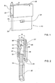
Fig. 1 is a general view of two members of a coupling in accordance with one embodiment of the present invention; -
Fig. 2 is a cross-sectional view of the coupling members shown inFig. 1 , taken along the line A-A , during their assembling into the coupling; -
Figs. 3A, 3B and 3C illustrate different stages of the assembling process shown inFig. 2 ; and -
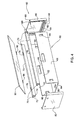
Fig. 4 is an exploded view of a container assembled as shown inFigs. 3A to 3C . - A
coupling 10 between ametal sheet member 20 and a plastic receivingmember 30 shown inFigs. 1 and 2 , according to one embodiment of the present invention, will be described with reference toFigs. 3A, 3B and 3C , which illustrate in detail the assembling process of thecoupling 10, based on the insertion of thesheet 20 into the receivingmember 30 in the direction of insertion I. - Referring to
Figs. 1 and 2 , themetal sheet member 20 has anedge 22 of a thickness T and is formed with anaperture 24 at a distance d2 from theedge 22. Thereceiving member 30 is formed with arecess 32 of a width W having abottom 37 andside walls 38' and 38", that are thin compared to the width W of the recess, providing it with required measure of elasticity. - The
recess 32 is further provided withspacers 34 formed integrally with one of the sidewalls thereof, for instance first side wall 38'. The spacers have a thicker cross section than the sidewalls, and are therefore stronger than the side walls and facilitate the rigidity of the recess. Thespacers 34 define, with thesecond side wall 38", agroove 36 of a width w, which meets the condition T < w < W. - The
recess 32 further comprises at least oneprojection 40 protruding into thegroove 36, integrally formed with thesecond side wall 38". The projection has afront face 42 slanted with respect to the direction of insertion I and arear face 44 perpendicular to the direction I. Theprojection 40 is located on theside wall 38" at a distance d1 from thebottom 37 of therecess 32, wherein d1 is equal to or greater than the distance d2 between theaperture 24 in themetal sheet member 20 and itsedge 22. - The coupling between the sheet and the receiving member is obtained by the insertion of the
edge 22 of themetal sheet member 20 into thegroove 36 in the direction I as shown inFigs. 3A, 3B and 3C . - The
groove 36 in the receivingmember 30 slidingly receives theedge 22 of themetal sheet member 20 with theprojection 40 snap-fitting in theaperture 24 therein, thereby providing a secure coupling between thesheet member 20 and the receivingmember 30. - When the
edge 22 of thesheet member 20 is inserted into thegroove 36 as shown inFig. 3A , the projection is pressed out of the groove, thanks to the elastic properties of theside walls 38' and 38" and thanks to the slantedfront face 42, as shown inFig. 3B . The advancement of theedge 22 is enabled to the point where theaperture 24 is aligned with theprojection 40 so that the projection snap-fits in the aperture as shown inFig.3C . Therear face 44 being perpendicular to the direction I is interacting with the aperture to prevent withdrawal of the sheet member out of the groove in a direction opposite to I. Therefore a secure and durable coupling is provided between thesheet member 20 and the receivingmember 30. - The coupling obtained by assembling the sheet and receiving members as described above may have a plurality of applications and may be used in the production of different products. One such product is a container that has to be rigid and durable and, at the same time, lightweight and low-cost.
-
Fig. 4 illustrates acontainer 50 comprising aU-shaped base 60 made of ametal sheet 61 of a thickness t, twoplastic rulers 70, twoplastic end walls 80 and acover 90. - The
U-shaped base 60 has a couple of essentially straight side edges 62, and a couple of U-shaped end edges 64. At least one opening or an aperture, 66 is formed in thebase 60, adjacent each of its four edges. - The
plastic rulers 70 are formed withrecesses 72 of a width w, greater than the width t of the edge of thebase 60, defined by sidewalls 74 and designed in the same manner as therecess 32 inFigs. 1 to 3 .Recesses 72 are adapted to slidingly receive side edges 62. - Similarly, the
end walls 80 are formed withrecesses 82 bound by sidewalls 84, adapted to slidingly receive the end edges 64 of thebase 60. - In addition, the
plastic rulers 70 are provided with two ends 79, and theend walls 80 are formed with two corresponding sockets 89. The ends 79 are adapted to fit into the sockets 89 upon the assembly of thecontainer 50, thereby providing a secure connection therebetween. - Assembling the container comprises the steps of: securing the two
plastic rulers 70 to the side edges 62 and then securing the twoend walls 80 to the couple of the end edges 64, thereby coupling the sockets 89 in the end walls to theends 79 in the plastic rulers to form thecontainer 50, by using the principles of the coupling described above with reference toFigs. 1 to 3 . - A
cover 90 is attached to thecontainer 50 by means of fasteners comprisingcorresponding fastening members plastic rulers 70 andcover 90, respectively. Designing thecontainer 50 with theside rulers 70 and endwalls 80 produced by injection molding, enables forming these parts in a design that facilitate the addition of thecover 90 in a simple way and with no extra cost.
Claims (13)
- A coupling (10) between a sheet member (20) with an edge (22) of a thickness T, having at least one opening (24) formed adjacent said edge, and a receiving member (30) formed with a recess (32) of a width W and spacers (34) defining within said recess a groove (36) of a width w, which meets the condition T < w < W, said recess comprising at least one projection (40) protruding into said groove, said groove being adapted to slidingly receive said edge (22) of the sheet member (20) with said projection (40) snap-fitting into said opening (24), thereby providing a secure coupling between the sheet and receiving members.
- A coupling in accordance with claim 1, wherein said projection (40) is adapted for being elastically pressed out of the groove (36), enabling said sheet member, during its insertion into said groove, to advance in an inward direction thereof into said groove until said opening is aligned with the projection to enable the projection to be snap-fit in the opening (24).
- A coupling in accordance with claim 2, wherein the opening (24) in said sheet member (20) and said projection (40) have a geometry that prevents withdrawal of the sheet member outwardly from the groove when the projection is snap-fit in the opening (24).
- A coupling in accordance with claim 3, wherein said projection (40) is formed with a front face, adapted to be the first face to contact said edge of the sheet member (20) when the sheet member is inserted into the groove (36), wherein said front face is slanted with respect to the inward direction, enabling the front edge to easily bias the projection out of the groove, when inserting the sheet member into the groove.
- A coupling in accordance with claim 3, wherein the projection (40) is formed with a rear face (44) that is oriented perpendicular to the inward direction, so that when the projection (40) is snap-fit in the opening (24), it interacts with the opening to prevent withdrawal of the sheet member out of the groove.
- A coupling in accordance with any one of claims 1 to 5, wherein said recess (32) is formed with sidewalls providing it with elasticity, and wherein said projection is integrally formed with one of said sidewalls.
- A coupling in accordance with any one of claims 1 to 6, wherein said recess (32) in said receiving member (30) is designed with sidewalls of a uniform wall-thickness.
- A coupling in accordance with claim 7, wherein the sidewalls of said recess (32), are thin compared to the width W of the recess.
- A coupling in accordance with claim 6, 7 or 8, wherein said spacers (34) are formed integrally with at least one of said sidewalls.
- A coupling in accordance with any one of claims 1 to 9, wherein said opening (24) is an aperture spaced from the edge.
- A coupling in accordance with any one of the preceding claims, adapted for use in assembling a container (50) comprising:(a) a base (60) in the form of a U-shaped sheet having a couple of essentially straight side edges (62), and a couple of U-shaped end edges, with at least one opening formed on said sheet adjacent each of said edges;(b) two rulers (70), each formed with a groove adapted to slidingly receive one of said side edges, and at least one projection protruding into said groove, adapted to interact with said at least one opening in said sheet adjacent said side edge to provide a secure coupling between the sheet and each of the rulers upon the insertion of the side edges into the groove;(c) two end walls (80), each formed with a U-shaped groove adapted to slidingly receive one of said end edges, and at least one projection protruding into each of said grooves, adapted to interact with said at least one opening (66) in said sheet adjacent said end edge to provide a secure coupling between the sheet and each of the end walls upon the insertion of one of said end edges into one of said U-shaped grooveswherein assembling said container comprises the steps of: securing said two rulers (70) to said side edges (62) and securing said two end walls (80) to said couple of end edges.
- A coupling in accordance with claim 11, wherein in said container (50) each of said rulers (70) has two ends, and each of said two end walls (80) is formed with two sockets (89), wherein said ends are adapted to snap-fit into said sockets (89) upon assembly of said container (50) thereby providing a secure connection therebetween.
- A coupling in accordance with claim 11 or 12, wherein said container further comprises a cover (90), and wherein said rulers (70) and said end walls (80) are adapted to securely engage said cover (90).
Applications Claiming Priority (2)
| Application Number | Priority Date | Filing Date | Title |
|---|---|---|---|
| US10/714,553 US7200899B2 (en) | 2003-11-17 | 2003-11-17 | Method for connecting plastic elements to metal sheets and constructions |
| PCT/IL2004/001004 WO2005047711A1 (en) | 2003-11-17 | 2004-11-03 | Method for connecting plastic elements to metal sheets |
Publications (2)
| Publication Number | Publication Date |
|---|---|
| EP1721083A1 EP1721083A1 (en) | 2006-11-15 |
| EP1721083B1 true EP1721083B1 (en) | 2009-08-19 |
Family
ID=34574012
Family Applications (1)
| Application Number | Title | Priority Date | Filing Date |
|---|---|---|---|
| EP04799313A Expired - Lifetime EP1721083B1 (en) | 2003-11-17 | 2004-11-03 | Method for connecting plastic elements to metal sheets |
Country Status (5)
| Country | Link |
|---|---|
| US (1) | US7200899B2 (en) |
| EP (1) | EP1721083B1 (en) |
| AT (1) | ATE440223T1 (en) |
| DE (1) | DE602004022718D1 (en) |
| WO (1) | WO2005047711A1 (en) |
Families Citing this family (13)
| Publication number | Priority date | Publication date | Assignee | Title |
|---|---|---|---|---|
| US7520404B2 (en) * | 2006-03-10 | 2009-04-21 | Ivonis Mazzarolo | Paper food container with injection molded top rim structure and method of manufacturing same |
| FR2908379B1 (en) * | 2006-11-13 | 2009-02-13 | Faurecia Bloc Avant | ASSEMBLY FOR A MOTOR VEHICLE, IN PARTICULAR FOR THE ASSEMBLY OF A BUMPER AND A BUMPER EXCAVATOR |
| US20080317549A1 (en) * | 2007-06-20 | 2008-12-25 | Magna International Inc. | Vehicle front end module to grille connective arrangement |
| EP2098816B1 (en) * | 2008-03-03 | 2017-06-21 | Hultafors Group AB | Folding rule with protective end cap |
| US10022856B2 (en) * | 2010-01-28 | 2018-07-17 | The Stanley Works Israel Ltd. | Metal and plastic container |
| CN203827662U (en) * | 2014-01-22 | 2014-09-10 | 光宝电子(广州)有限公司 | Structure for fixing metal part to plastic part |
| ES2805199T3 (en) * | 2015-01-29 | 2021-02-11 | Essity Hygiene & Health Ab | Sheet metal outer surface dispenser and manufacturing method |
| ITRA20150011U1 (en) * | 2015-05-13 | 2016-11-13 | Rexsitt Italia S R L | AUTOMATIC HOOKING DEVICE. |
| DE102016225610A1 (en) * | 2016-12-20 | 2018-06-21 | BSH Hausgeräte GmbH | Door racks with a base latched to a base and household refrigeration appliance with a door rack |
| US20190054532A1 (en) * | 2017-08-21 | 2019-02-21 | Divergent Technologies, Inc. | Systems and methods for bridging components |
| JP7048290B2 (en) * | 2017-12-11 | 2022-04-05 | 株式会社シマノ | Fishing fish tray |
| DK201870528A1 (en) * | 2018-08-16 | 2020-03-10 | Maersk Container Industry A/S | Connections between panels in intermodal containers and method of assembly of such connections |
| CN113859377A (en) * | 2021-10-26 | 2021-12-31 | 烟台正海合泰科技股份有限公司 | PHC products and their PHC substrates and plastic parts |
Family Cites Families (8)
| Publication number | Priority date | Publication date | Assignee | Title |
|---|---|---|---|---|
| GB682776A (en) | 1949-09-23 | 1952-11-19 | William Cookson | Improvements in or relating to joints for sheet material |
| AU516651B2 (en) * | 1977-05-12 | 1981-06-18 | Yoshida Kogyo K.K. | Ornamental attachment for slide fastener |
| US4444321A (en) * | 1982-05-17 | 1984-04-24 | William Carlstrom | Bracket structure for supporting a shelf or partition of a display case or the like |
| IT216797Z2 (en) * | 1989-07-27 | 1991-10-03 | Evoluzione Di Federico Gonella | FOLDABLE BOX BODY STRUCTURE FOR CONTAINING OBJECTS IN GENERAL. |
| US5413236A (en) * | 1993-07-02 | 1995-05-09 | Kenevan; Timothy P. | Modular shipping container |
| US6213328B1 (en) * | 1998-12-31 | 2001-04-10 | 500 Group Inc. | Method and construction for connecting together metal and plastic elements |
| US6261026B1 (en) * | 1999-07-02 | 2001-07-17 | Gravity Tank, Inc. | Resiliently mounted clip for indexed poles |
| DE20313249U1 (en) | 2003-08-25 | 2003-10-30 | HEMA Maschinen- und Apparateschutz GmbH, 63500 Seligenstadt | Interlocking join for machine tool housing panels have spring clip secured to first panel and engaging in matching slits in second panel |
-
2003
- 2003-11-17 US US10/714,553 patent/US7200899B2/en not_active Expired - Fee Related
-
2004
- 2004-11-03 AT AT04799313T patent/ATE440223T1/en not_active IP Right Cessation
- 2004-11-03 WO PCT/IL2004/001004 patent/WO2005047711A1/en not_active Ceased
- 2004-11-03 EP EP04799313A patent/EP1721083B1/en not_active Expired - Lifetime
- 2004-11-03 DE DE602004022718T patent/DE602004022718D1/en not_active Expired - Lifetime
Also Published As
| Publication number | Publication date |
|---|---|
| WO2005047711A1 (en) | 2005-05-26 |
| DE602004022718D1 (en) | 2009-10-01 |
| US20050103792A1 (en) | 2005-05-19 |
| EP1721083A1 (en) | 2006-11-15 |
| US7200899B2 (en) | 2007-04-10 |
| ATE440223T1 (en) | 2009-09-15 |
Similar Documents
| Publication | Publication Date | Title |
|---|---|---|
| US7200899B2 (en) | Method for connecting plastic elements to metal sheets and constructions | |
| US6955514B2 (en) | Connector with male part for final fixing | |
| CN101448555B (en) | Knockdown block | |
| US6319037B1 (en) | Retention clip for card edge connector | |
| JPH0422078A (en) | connector | |
| US20150375797A1 (en) | Elastically averaged alignment systems and methods | |
| EP3808998B1 (en) | Dual component sealing fastener and coupling assembly including same | |
| JP7514244B2 (en) | Connection systems for furniture parts | |
| TW201317168A (en) | Packing mechanism | |
| WO2002026086A1 (en) | A joint arrangement for demountable structure | |
| JP2018520321A (en) | Releasable coupling system | |
| US20240254768A1 (en) | Connection arrangement for panels | |
| US20240251941A1 (en) | Cabinet assembly arrangement | |
| US20140090509A1 (en) | Mechanical assembly of the press-button type, and application to an electrical apparatus | |
| KR200392131Y1 (en) | Box Corner Connecting Angle | |
| JPH06255665A (en) | Cup cover | |
| JP7144782B2 (en) | Electrical contact consisting of sheet metal with plastically elongated latching tongue and/or limit stop and method of forming same | |
| JP2022138632A (en) | shelf | |
| JP5546840B2 (en) | Connector | |
| CN114233735A (en) | Assembly module | |
| CN210623335U (en) | Buckle subassembly, car light and vehicle | |
| US20240258776A1 (en) | Hybrid emt coupling | |
| JPH0610929A (en) | Plug-in-type connector | |
| JP2023118322A (en) | connector | |
| KR20000013636U (en) | Plate of refrigerator |
Legal Events
| Date | Code | Title | Description |
|---|---|---|---|
| PUAI | Public reference made under article 153(3) epc to a published international application that has entered the european phase |
Free format text: ORIGINAL CODE: 0009012 |
|
| 17P | Request for examination filed |
Effective date: 20060607 |
|
| AK | Designated contracting states |
Kind code of ref document: A1 Designated state(s): AT BE BG CH CY CZ DE DK EE ES FI FR GB GR HU IE IS IT LI LU MC NL PL PT RO SE SI SK TR |
|
| DAX | Request for extension of the european patent (deleted) | ||
| 17Q | First examination report despatched |
Effective date: 20080715 |
|
| GRAP | Despatch of communication of intention to grant a patent |
Free format text: ORIGINAL CODE: EPIDOSNIGR1 |
|
| GRAS | Grant fee paid |
Free format text: ORIGINAL CODE: EPIDOSNIGR3 |
|
| GRAA | (expected) grant |
Free format text: ORIGINAL CODE: 0009210 |
|
| AK | Designated contracting states |
Kind code of ref document: B1 Designated state(s): AT BE BG CH CY CZ DE DK EE ES FI FR GB GR HU IE IS IT LI LU MC NL PL PT RO SE SI SK TR |
|
| REG | Reference to a national code |
Ref country code: GB Ref legal event code: FG4D |
|
| REG | Reference to a national code |
Ref country code: CH Ref legal event code: EP |
|
| REG | Reference to a national code |
Ref country code: IE Ref legal event code: FG4D |
|
| REF | Corresponds to: |
Ref document number: 602004022718 Country of ref document: DE Date of ref document: 20091001 Kind code of ref document: P |
|
| PG25 | Lapsed in a contracting state [announced via postgrant information from national office to epo] |
Ref country code: SE Free format text: LAPSE BECAUSE OF FAILURE TO SUBMIT A TRANSLATION OF THE DESCRIPTION OR TO PAY THE FEE WITHIN THE PRESCRIBED TIME-LIMIT Effective date: 20090819 Ref country code: AT Free format text: LAPSE BECAUSE OF FAILURE TO SUBMIT A TRANSLATION OF THE DESCRIPTION OR TO PAY THE FEE WITHIN THE PRESCRIBED TIME-LIMIT Effective date: 20090819 Ref country code: FI Free format text: LAPSE BECAUSE OF FAILURE TO SUBMIT A TRANSLATION OF THE DESCRIPTION OR TO PAY THE FEE WITHIN THE PRESCRIBED TIME-LIMIT Effective date: 20090819 Ref country code: IS Free format text: LAPSE BECAUSE OF FAILURE TO SUBMIT A TRANSLATION OF THE DESCRIPTION OR TO PAY THE FEE WITHIN THE PRESCRIBED TIME-LIMIT Effective date: 20091219 Ref country code: ES Free format text: LAPSE BECAUSE OF FAILURE TO SUBMIT A TRANSLATION OF THE DESCRIPTION OR TO PAY THE FEE WITHIN THE PRESCRIBED TIME-LIMIT Effective date: 20091130 |
|
| NLV1 | Nl: lapsed or annulled due to failure to fulfill the requirements of art. 29p and 29m of the patents act | ||
| PG25 | Lapsed in a contracting state [announced via postgrant information from national office to epo] |
Ref country code: SI Free format text: LAPSE BECAUSE OF FAILURE TO SUBMIT A TRANSLATION OF THE DESCRIPTION OR TO PAY THE FEE WITHIN THE PRESCRIBED TIME-LIMIT Effective date: 20090819 Ref country code: PL Free format text: LAPSE BECAUSE OF FAILURE TO SUBMIT A TRANSLATION OF THE DESCRIPTION OR TO PAY THE FEE WITHIN THE PRESCRIBED TIME-LIMIT Effective date: 20090819 Ref country code: NL Free format text: LAPSE BECAUSE OF FAILURE TO SUBMIT A TRANSLATION OF THE DESCRIPTION OR TO PAY THE FEE WITHIN THE PRESCRIBED TIME-LIMIT Effective date: 20090819 |
|
| PG25 | Lapsed in a contracting state [announced via postgrant information from national office to epo] |
Ref country code: CY Free format text: LAPSE BECAUSE OF FAILURE TO SUBMIT A TRANSLATION OF THE DESCRIPTION OR TO PAY THE FEE WITHIN THE PRESCRIBED TIME-LIMIT Effective date: 20090819 Ref country code: BG Free format text: LAPSE BECAUSE OF FAILURE TO SUBMIT A TRANSLATION OF THE DESCRIPTION OR TO PAY THE FEE WITHIN THE PRESCRIBED TIME-LIMIT Effective date: 20091119 Ref country code: PT Free format text: LAPSE BECAUSE OF FAILURE TO SUBMIT A TRANSLATION OF THE DESCRIPTION OR TO PAY THE FEE WITHIN THE PRESCRIBED TIME-LIMIT Effective date: 20091221 |
|
| PG25 | Lapsed in a contracting state [announced via postgrant information from national office to epo] |
Ref country code: CZ Free format text: LAPSE BECAUSE OF FAILURE TO SUBMIT A TRANSLATION OF THE DESCRIPTION OR TO PAY THE FEE WITHIN THE PRESCRIBED TIME-LIMIT Effective date: 20090819 Ref country code: DK Free format text: LAPSE BECAUSE OF FAILURE TO SUBMIT A TRANSLATION OF THE DESCRIPTION OR TO PAY THE FEE WITHIN THE PRESCRIBED TIME-LIMIT Effective date: 20090819 Ref country code: RO Free format text: LAPSE BECAUSE OF FAILURE TO SUBMIT A TRANSLATION OF THE DESCRIPTION OR TO PAY THE FEE WITHIN THE PRESCRIBED TIME-LIMIT Effective date: 20090819 Ref country code: EE Free format text: LAPSE BECAUSE OF FAILURE TO SUBMIT A TRANSLATION OF THE DESCRIPTION OR TO PAY THE FEE WITHIN THE PRESCRIBED TIME-LIMIT Effective date: 20090819 |
|
| PG25 | Lapsed in a contracting state [announced via postgrant information from national office to epo] |
Ref country code: SK Free format text: LAPSE BECAUSE OF FAILURE TO SUBMIT A TRANSLATION OF THE DESCRIPTION OR TO PAY THE FEE WITHIN THE PRESCRIBED TIME-LIMIT Effective date: 20090819 |
|
| PLBE | No opposition filed within time limit |
Free format text: ORIGINAL CODE: 0009261 |
|
| STAA | Information on the status of an ep patent application or granted ep patent |
Free format text: STATUS: NO OPPOSITION FILED WITHIN TIME LIMIT |
|
| PG25 | Lapsed in a contracting state [announced via postgrant information from national office to epo] |
Ref country code: BE Free format text: LAPSE BECAUSE OF FAILURE TO SUBMIT A TRANSLATION OF THE DESCRIPTION OR TO PAY THE FEE WITHIN THE PRESCRIBED TIME-LIMIT Effective date: 20090819 Ref country code: MC Free format text: LAPSE BECAUSE OF NON-PAYMENT OF DUE FEES Effective date: 20091130 |
|
| REG | Reference to a national code |
Ref country code: CH Ref legal event code: PL |
|
| 26N | No opposition filed |
Effective date: 20100520 |
|
| PG25 | Lapsed in a contracting state [announced via postgrant information from national office to epo] |
Ref country code: GR Free format text: LAPSE BECAUSE OF FAILURE TO SUBMIT A TRANSLATION OF THE DESCRIPTION OR TO PAY THE FEE WITHIN THE PRESCRIBED TIME-LIMIT Effective date: 20091120 Ref country code: CH Free format text: LAPSE BECAUSE OF NON-PAYMENT OF DUE FEES Effective date: 20091130 Ref country code: LI Free format text: LAPSE BECAUSE OF NON-PAYMENT OF DUE FEES Effective date: 20091130 Ref country code: IE Free format text: LAPSE BECAUSE OF NON-PAYMENT OF DUE FEES Effective date: 20091103 |
|
| PG25 | Lapsed in a contracting state [announced via postgrant information from national office to epo] |
Ref country code: IT Free format text: LAPSE BECAUSE OF FAILURE TO SUBMIT A TRANSLATION OF THE DESCRIPTION OR TO PAY THE FEE WITHIN THE PRESCRIBED TIME-LIMIT Effective date: 20090819 |
|
| PG25 | Lapsed in a contracting state [announced via postgrant information from national office to epo] |
Ref country code: LU Free format text: LAPSE BECAUSE OF NON-PAYMENT OF DUE FEES Effective date: 20091103 |
|
| PG25 | Lapsed in a contracting state [announced via postgrant information from national office to epo] |
Ref country code: HU Free format text: LAPSE BECAUSE OF FAILURE TO SUBMIT A TRANSLATION OF THE DESCRIPTION OR TO PAY THE FEE WITHIN THE PRESCRIBED TIME-LIMIT Effective date: 20100220 |
|
| PG25 | Lapsed in a contracting state [announced via postgrant information from national office to epo] |
Ref country code: TR Free format text: LAPSE BECAUSE OF FAILURE TO SUBMIT A TRANSLATION OF THE DESCRIPTION OR TO PAY THE FEE WITHIN THE PRESCRIBED TIME-LIMIT Effective date: 20090819 |
|
| REG | Reference to a national code |
Ref country code: FR Ref legal event code: PLFP Year of fee payment: 12 |
|
| REG | Reference to a national code |
Ref country code: FR Ref legal event code: PLFP Year of fee payment: 13 |
|
| PGFP | Annual fee paid to national office [announced via postgrant information from national office to epo] |
Ref country code: GB Payment date: 20161130 Year of fee payment: 13 Ref country code: FR Payment date: 20161128 Year of fee payment: 13 |
|
| PGFP | Annual fee paid to national office [announced via postgrant information from national office to epo] |
Ref country code: DE Payment date: 20170131 Year of fee payment: 13 |
|
| REG | Reference to a national code |
Ref country code: DE Ref legal event code: R119 Ref document number: 602004022718 Country of ref document: DE |
|
| GBPC | Gb: european patent ceased through non-payment of renewal fee |
Effective date: 20171103 |
|
| REG | Reference to a national code |
Ref country code: FR Ref legal event code: ST Effective date: 20180731 |
|
| PG25 | Lapsed in a contracting state [announced via postgrant information from national office to epo] |
Ref country code: DE Free format text: LAPSE BECAUSE OF NON-PAYMENT OF DUE FEES Effective date: 20180602 Ref country code: FR Free format text: LAPSE BECAUSE OF NON-PAYMENT OF DUE FEES Effective date: 20171130 |
|
| PG25 | Lapsed in a contracting state [announced via postgrant information from national office to epo] |
Ref country code: GB Free format text: LAPSE BECAUSE OF NON-PAYMENT OF DUE FEES Effective date: 20171103 |