EP1720665B1 - Method of defining, tracing and removing of the portion of defective rod-shaped elements transported by tobacco industry production line conveyor and a system which allows defining, tracing and removing of the portion of defective rod-shaped elements from the conveyor at tobacco industry production line - Google Patents
Method of defining, tracing and removing of the portion of defective rod-shaped elements transported by tobacco industry production line conveyor and a system which allows defining, tracing and removing of the portion of defective rod-shaped elements from the conveyor at tobacco industry production line Download PDFInfo
- Publication number
- EP1720665B1 EP1720665B1 EP04800233A EP04800233A EP1720665B1 EP 1720665 B1 EP1720665 B1 EP 1720665B1 EP 04800233 A EP04800233 A EP 04800233A EP 04800233 A EP04800233 A EP 04800233A EP 1720665 B1 EP1720665 B1 EP 1720665B1
- Authority
- EP
- European Patent Office
- Prior art keywords
- conveyor
- feed
- defective
- feed station
- elements
- Prior art date
- Legal status (The legal status is an assumption and is not a legal conclusion. Google has not performed a legal analysis and makes no representation as to the accuracy of the status listed.)
- Ceased
Links
- 230000002950 deficient Effects 0.000 title claims description 67
- 238000000034 method Methods 0.000 title claims description 30
- 238000004519 manufacturing process Methods 0.000 title claims description 11
- 241000208125 Nicotiana Species 0.000 title claims description 9
- 235000002637 Nicotiana tabacum Nutrition 0.000 title claims description 9
- 238000005259 measurement Methods 0.000 claims description 17
- 238000012360 testing method Methods 0.000 claims description 7
- 238000012937 correction Methods 0.000 claims description 5
- 238000001514 detection method Methods 0.000 claims description 3
- 238000003908 quality control method Methods 0.000 claims description 2
- 238000012545 processing Methods 0.000 description 4
- 235000019504 cigarettes Nutrition 0.000 description 3
- 230000003213 activating effect Effects 0.000 description 1
- 230000000694 effects Effects 0.000 description 1
- 238000009434 installation Methods 0.000 description 1
- 230000003287 optical effect Effects 0.000 description 1
- 230000011514 reflex Effects 0.000 description 1
- 230000001360 synchronised effect Effects 0.000 description 1
Images
Classifications
-
- B—PERFORMING OPERATIONS; TRANSPORTING
- B07—SEPARATING SOLIDS FROM SOLIDS; SORTING
- B07C—POSTAL SORTING; SORTING INDIVIDUAL ARTICLES, OR BULK MATERIAL FIT TO BE SORTED PIECE-MEAL, e.g. BY PICKING
- B07C5/00—Sorting according to a characteristic or feature of the articles or material being sorted, e.g. by control effected by devices which detect or measure such characteristic or feature; Sorting by manually actuated devices, e.g. switches
- B07C5/36—Sorting apparatus characterised by the means used for distribution
Definitions
- the subject of the invention is a method used to determine the volume of a portion of defective rod-shaped elements manufactured by a producing machine, which are located on variable-length conveyor and transported towards receiving device, with reference to a portion of elements being stored in variable-volume buffer magazine of a type "first in-first out", including removal of the mentioned portion prior to be entered into the receiving device, moreover, allowing the defining and tracing of the defective rod-shaped elements and their removal from the conveyor prior to be entered into the receiving device, from variable-volume buffer magazine of the type "first in - first out", which is located between producing machine and receiving device.
- German invention DE 10216069 describes a method and device used in tobacco processing.
- a product, especially a cigarette, when manufactured by the machine comes through several different processing phases, which can be checked or controlled with use of appropriate sensors and actuators.
- the sensor-collected information about cigarettes can be used by the cigarette making machine control system, for example for rejection of defective elements.
- the sensor-collected information is gathered synchronously, where the machine pulse is assigned to a product asynchronously to the machine pulse, whereas depending on this information appropriate action to a product is executed with use of an actuator, synchronously to the machine pulse.
- a significant feature of the method of defining, tracing and rejection of defective elements found on the tobacco industry production line conveyor, particularly elements manufactured by the producing machine and occurring on the variable-length conveyor, in variable-volume buffer magazine of the type "first in - first out" located between producing machine and receiving device, where quality of rod-shaped elements is determined within this zone after they leave producing machine but before they enter the receiving device, where defective rod-shaped elements are removed from the conveyor within this zone prior to be entered into receiving device, is related to assigning the information about the defectiveness to the first and last defective rod-shaped element detected by the control-measuring device within a portion which was delivered to the in-feed station, and tracing of the marked information takes place within a zone extending from the control-measuring device to the rejecting device, with use of special in-feed counter located in the out-feed station, whereas signals corresponding to the information about initial and final part of the portion of defective elements, which when processed in the machine control system are then transferred to the rejecting device, in order to remove
- Information about defectiveness of the rod-shaped element is assigned by means of appropriate marking of this element, whereas this activity is executed after the element leaves control-measuring device, while in rejection device all rod-shaped elements located on the conveyor, derived from quality measurement in control-measuring device, prior to detection of the defective elements, up to the last detected defective element, are removed.
- information related to the defectiveness of the rod-shaped element is gathered by assigning the element to a corresponding segment of the conveyor, whereas the conveyor is divided into finite number of identical segments. Each segment can be marked electronically with a record allowing identification of this element by in-feed counter located within the in-feed station and out-feed counter located within the out-feed station.
- tracing of the portion of defective elements can be done by means of counting the number of pulses equivalent to the segments by the in-feed counter located within the in-feed station and the out-feed counter located within the out-feed station, whereas at the same time, a correction of the counters indication is made by means of calibration of the temporary length of the conveyor, between in-feed and out-feed stations, and corrected signal assigned to the first and the last defective element is sent to the rejection device, which removes all rod-shaped elements located on the conveyor, within a time period from the quality measurement made by the measuring device up to the last detected defective element.
- Calibration of the temporary length of the conveyor is made by means of counting the number of pulses by out-feed counter within the out-feed station, since the calibrating element enters in-feed station, being detected by in-feed detector, and comparing the real counted pulses with theoretical number of pulses equivalent to the temporary length of the conveyor stored in the control system, whereas, if the numbers of pulses - real and theoretical - are not equal, a reading error of the initial and final part of the portion of defective elements on the conveyor occurs, and the error value is determined by a difference between theoretical number of pulses and number of pulses really counted, as well.
- the control system automatically corrects the number of pulses related to the temporary length of the conveyor, and the corrected, new value, as a theoretical number of pulses assigned to temporary length of the conveyor, is introduced to the machine control system, and in case of repetition of the error, counters must be checked manually by the operating personnel. Constant number of pulses between calibration cycles is assigned to the same length of the conveyor, and the calibration is made automatically and continuously, whereas each detection of the calibration element by in-feed detector located within the in-feed station commences new calibration process.
- signal of the beginning of portion of the defective elements delivered by the control-measuring device is assigned to the theoretical temporary conveyor length, and out-feed counter located within the out-feed station starts counting the pulses corresponding to temporary, theoretical conveyor length, whereas total number of counted number of pulses indicate, that portion of defective elements entered the out-feed station.
- Signal of final part of the portion of defective elements is sent from the control-measuring device to the machine control system, where a difference of pulses between initial and final part of the defective elements red by the in-feed counter located within the in-feed station is determined, and the determined number of pulses is counted by the out-feed counter located within the out-feed station.
- Co-operation of the conveyor with the in-feed and out-feed stations is slip-less. Described optional methods guarantee automatic removal of the defective, rod-shaped elements, what eliminates loses related to manual control of the rejecting device.
- Out-feed station comprising the out-feed counter and the out-feed detector, which is installed at the side of the producing machine within the constant length area of the conveyor, and out-feed station comprising the out-feed counter and the out-feed detector installed at the side of the receiving device contribute substantial solutions of the present invention, as the system allows determining, tracing and removing of the rod-shaped elements from the conveyor installed within the tobacco industry production line, particularly elements manufactured by the producing machine which are present on the variable-length conveyor, within variable-volume buffer magazine of the type "first in - first out", which is located between the producing machine and the receiving device, equipped with a control-measuring device installed also within the area between the producing machine and receiving device, including rejection device installed before the receiving device, whereas the conveyor is built of identical segments and equipped with a calibration element, which is assigned to suitably marked segment of the conveyor.
- the described system allows precise determining of the initial and final part of the portion of effective rod-shaped elements, which is transferred from the producing machine onto the conveyor, and the portion is traced along whole, variable length of the conveyor, and removing definite portion of the elements before they enter the receiving machine, moreover, the system also allows automatic correction of the signal activating the rejecting device in case of improper reading of the in-feed/out-feed counter.
- Conveyor 1 is located between producing machine and receiving device - not shown in the Fig. 1, particularly variable-volume buffer-type magazine of a type "first in - first out", for example magazine described of Polish patent No. PL 186270 , which consists of transport sector 2 conveying multi-layered stack 3 of rod-shaped elements 4 and return sector 5.
- In-feed station 6 is located at the in-feed part of the transport sector 2
- out-feed section 7 is located at the out-feed part of the transport sector 2.
- Conveyor 1. consists of identical segments 8, whereas one of the segments 8, differently marked, is used as a calibration element 9.
- Rod-shaped elements 4 manufactured by producing machine are transferred in form of multi-layered stack 3 to transport sector 2 of the variable-length conveyor 1.
- Control-measuring device 14 takes, with assumed frequency, samples of elements 4 for quality test. In case when a defective element 4 is detected, information about its defectiveness is assigned to the element 4 and sent to the machine control system 20. If one of the sequent tests made by the control-measuring device 14 proves that the element 4 is no longer defective, that is assumed as a final part of portion of defective elements 4, and appropriate information is sent to the control system 20. Information about defectiveness is assigned to the defective element 4 by means of appropriate marking of the element 4, after it leaves the control-measuring device 14.
- Stack 3 of elements 4 moving along the conveyor 1 is tracked by in-feed counter 10 located within in-feed station 6 and by out-feed counter 15 located within out-feed station 7, and signals informing about presence of initial and final part of the defective elements 4 are suitably processed in the machine control system 20 and then transferred to the rejecting device 19 in order to remove the elements from moving stack 3, whereas rejecting device removes all elements 4 located on the conveyor 1, since quality measurement is made by the control-measuring device14, prior to measurement detecting the defective element 4, up to the last element 4, before the proper quality element 4 is detected.
- Manufactured by the producing machine rod-shaped elements 4 are transferred in form of multi-layered stack 3 into transport sector 2 of the variable-length conveyor 1.
- Control-measuring device 14 takes, with assumed frequency, samples of elements 4 for quality test. When a defective element 4 is detected, the information about defectiveness is assigned to segment 8 of the conveyor 1, where element 4 is located, whereas, the conveyor is divided into finite number of identical segments 8. If one on sequent tests made by the control-measuring device 14 proves that the element 4 is no longer defective, it means that this is the final part of the portion of defective elements, and information about this fact is sent to control system 20.
- Each segment 8 is electronically marked, for example with a bar code allowing identification of the segment 8 by in-feed counter 10 located within in-feed station 6, and by out-feed counter 15 located within out-feed station 7.
- Signals about appearance of segments 8 corresponding to initial and final part of the portion of defective elements 4 are processed in the machine control system 20 and sent to rejecting device 19 in order to remove moving stack 3, whereas, rejecting device 19 removes all elements 4 which are located on the conveyor 1, since quality control measurement made by control-measuring device 14, prior to measurement detecting defective element 4, up to the last element 4, before proper element 4, is detected.
- Manufactured by the producing machine rod-shaped elements 4 are transferred in form of multi-layered stack 3 into the transport sector 2 of the variable-length conveyor 1.
- Control-measuring device 14 takes samples of elements 4 for quality test. When a defective element 4 is detected, the information about defectiveness is assigned to segment 8 of the conveyor 1, where element 4 is located, whereas, the conveyor is divided into finite number of identical segments 8. If one on sequent tests made by the control-measuring device 14 proves that the element 4 is no longer defective, it means that this is the final part of the portion of defective elements, and information about this fact is sent to the machine control system 20.
- Tracing of the portion of defective elements 4 is made by means of counting the number of pulses corresponding to segments 8 by in-feed counter 10 located within in-feed station 6, and by out-feed counter 15 located within out-feed station 7, whereas, synchronous correction of readings of the counters 10, 15 by means of calibration of the temporary length of the conveyor 1, between in-feed station 6 and out-feed station 7, and corrected to real value signal corresponding to the first and last defective element 4 is sent to the rejecting device 19, which removes all rod-shaped elements located on the conveyor 1, since quality measurement made by control-measuring device 14, prior to measurement detecting defective element 4 up to the last element 4 before measurement detecting proper element 4. Co-operation of the conveyor 1 with in-feed station 6 and out-feed station 7 is slip-less.
- Calibration of temporary length of the conveyor 1 is made by means of counting pulses by out-feed counter 15 located within out-feed station 7, in the period since the calibrated element 9, detected by in-feed detector, enter in-feed station 6, and then comparing the number of really counted pulses with theoretical number of pulses corresponding to temporary length of the conveyor 1 within transport sector 2, stored within the machine control system 20, whereas, if the mentioned numbers of pulses - real and theoretical - are not identical at the moment when the calibrating element 9 is detected by out-feed detector 16 located within out-feed station 7, a reading error of initial and final part of portion of defective element 4 present on the conveyor 1 occurs, and error magnitude is determined by difference between theoretical number of pulses and number of really counted pulses.
- Control system 20 automatically corrects a number of pulses corresponding to temporary length of the conveyor 1, introducing the new corrected value as a theoretical number of pulses for temporary length of the conveyor 1, and in a case of the error repetition, machine operator is obliged to check the counters, whereas, constant number of pulses between calibration cycles is assigned to the same length of the conveyor 1.
- the calibration is made automatically and continuously, and each detecting of the calibrating element 9 by in-feed detector 11 located within on-feed station 6 commences next calibration process.
- Signal announcing the initial part of portion of defective elements 4 delivered by control-measuring device 14 is assigned by the machine control system 20 to temporary length of the conveyor 1, and out-feed counter 15 located within out-feed station 7 commences counting pulses corresponding to number of pulses corresponding to temporary, theoretical length of the conveyor 1, whereas, total counting of the mentioned number of pulses indicates that portion of defective elements 4 reached out-feed station 7.
- Signal announcing that final part of portion of defective elements 4 is detected by control-measuring device 14, corresponding to the first good quality element 4, is sent to the machine control system, where the difference between number of pulses red by in-feed counter 10 located within in-feed station 6 and final part of portion of defective elements is determined, and mentioned number of pulses is counted by out-feed counter 15 located within out-feed station 7.
- the mentioned options can be superimposed or they can be mutually complemented, moreover, there is a possibility to define, track and remove several different portions of rod-shaped defective elements 4 located within transport sector 2 of the variable-length conveyor 1.
Landscapes
- Manufacturing Of Cigar And Cigarette Tobacco (AREA)
Description
- The subject of the invention is a method used to determine the volume of a portion of defective rod-shaped elements manufactured by a producing machine, which are located on variable-length conveyor and transported towards receiving device, with reference to a portion of elements being stored in variable-volume buffer magazine of a type "first in-first out", including removal of the mentioned portion prior to be entered into the receiving device, moreover, allowing the defining and tracing of the defective rod-shaped elements and their removal from the conveyor prior to be entered into the receiving device, from variable-volume buffer magazine of the type "first in - first out", which is located between producing machine and receiving device.
- In Tobacco Industry it often happens that during production of rod-shaped elements, some of these elements should not be used in the further processing, and the elements should be rejected. For example, a German invention
DE 10216069 describes a method and device used in tobacco processing. A product, especially a cigarette, when manufactured by the machine, comes through several different processing phases, which can be checked or controlled with use of appropriate sensors and actuators. The sensor-collected information about cigarettes can be used by the cigarette making machine control system, for example for rejection of defective elements. According to this method, the sensor-collected information is gathered synchronously, where the machine pulse is assigned to a product asynchronously to the machine pulse, whereas depending on this information appropriate action to a product is executed with use of an actuator, synchronously to the machine pulse. From the other side, another optical method of observation of external surface of rod-shaped elements during production process in Tobacco Industry, including description of the working stand, is known from a patent USA No.US 4644176 . In case of both mentioned inventions, both defining the rod-shaped elements end their rejection take place within the area of the machine producing the elements in question. In case of production lines producing rod-shaped elements, where a variable-volume conveyor working with system "first in - first out" is placed between product making machine and receiving device, the quality of rod-shaped elements delivered from the machine is controlled quantitatively with use of commonly known control or measuring devices. Portion of defective elements on the conveyor is marked manually, depending on reflex and experience of the machine operator. Likewise, removal of the marked portion prior to be entered into the receiving device is made manually, by consequent switching the valve 'ON' and 'OFF', and it also depends on individual skills of the machine operator. It should be mentioned that at the production rate of about 14 000 pieces of rod-shaped elements per minute, even a minor time inaccuracy of the manual marking and removing the defective elements can generate great loses, related both to rejection of good elements and transferring defective elements to further processing. - According to the present invention, a significant feature of the method of defining, tracing and rejection of defective elements found on the tobacco industry production line conveyor, particularly elements manufactured by the producing machine and occurring on the variable-length conveyor, in variable-volume buffer magazine of the type "first in - first out" located between producing machine and receiving device, where quality of rod-shaped elements is determined within this zone after they leave producing machine but before they enter the receiving device, where defective rod-shaped elements are removed from the conveyor within this zone prior to be entered into receiving device, is related to assigning the information about the defectiveness to the first and last defective rod-shaped element detected by the control-measuring device within a portion which was delivered to the in-feed station, and tracing of the marked information takes place within a zone extending from the control-measuring device to the rejecting device, with use of special in-feed counter located in the out-feed station, whereas signals corresponding to the information about initial and final part of the portion of defective elements, which when processed in the machine control system are then transferred to the rejecting device, in order to remove determined portion of the defective rod-shaped elements. Information about defectiveness of the rod-shaped element is assigned by means of appropriate marking of this element, whereas this activity is executed after the element leaves control-measuring device, while in rejection device all rod-shaped elements located on the conveyor, derived from quality measurement in control-measuring device, prior to detection of the defective elements, up to the last detected defective element, are removed. In alternative option of the invention, information related to the defectiveness of the rod-shaped element is gathered by assigning the element to a corresponding segment of the conveyor, whereas the conveyor is divided into finite number of identical segments. Each segment can be marked electronically with a record allowing identification of this element by in-feed counter located within the in-feed station and out-feed counter located within the out-feed station. Alternatively, tracing of the portion of defective elements can be done by means of counting the number of pulses equivalent to the segments by the in-feed counter located within the in-feed station and the out-feed counter located within the out-feed station, whereas at the same time, a correction of the counters indication is made by means of calibration of the temporary length of the conveyor, between in-feed and out-feed stations, and corrected signal assigned to the first and the last defective element is sent to the rejection device, which removes all rod-shaped elements located on the conveyor, within a time period from the quality measurement made by the measuring device up to the last detected defective element. Calibration of the temporary length of the conveyor is made by means of counting the number of pulses by out-feed counter within the out-feed station, since the calibrating element enters in-feed station, being detected by in-feed detector, and comparing the real counted pulses with theoretical number of pulses equivalent to the temporary length of the conveyor stored in the control system, whereas, if the numbers of pulses - real and theoretical - are not equal, a reading error of the initial and final part of the portion of defective elements on the conveyor occurs, and the error value is determined by a difference between theoretical number of pulses and number of pulses really counted, as well. The control system automatically corrects the number of pulses related to the temporary length of the conveyor, and the corrected, new value, as a theoretical number of pulses assigned to temporary length of the conveyor, is introduced to the machine control system, and in case of repetition of the error, counters must be checked manually by the operating personnel. Constant number of pulses between calibration cycles is assigned to the same length of the conveyor, and the calibration is made automatically and continuously, whereas each detection of the calibration element by in-feed detector located within the in-feed station commences new calibration process. In the machine control system, signal of the beginning of portion of the defective elements delivered by the control-measuring device is assigned to the theoretical temporary conveyor length, and out-feed counter located within the out-feed station starts counting the pulses corresponding to temporary, theoretical conveyor length, whereas total number of counted number of pulses indicate, that portion of defective elements entered the out-feed station. Signal of final part of the portion of defective elements is sent from the control-measuring device to the machine control system, where a difference of pulses between initial and final part of the defective elements red by the in-feed counter located within the in-feed station is determined, and the determined number of pulses is counted by the out-feed counter located within the out-feed station. Co-operation of the conveyor with the in-feed and out-feed stations is slip-less. Described optional methods guarantee automatic removal of the defective, rod-shaped elements, what eliminates loses related to manual control of the rejecting device.
- Out-feed station comprising the out-feed counter and the out-feed detector, which is installed at the side of the producing machine within the constant length area of the conveyor, and out-feed station comprising the out-feed counter and the out-feed detector installed at the side of the receiving device contribute substantial solutions of the present invention, as the system allows determining, tracing and removing of the rod-shaped elements from the conveyor installed within the tobacco industry production line, particularly elements manufactured by the producing machine which are present on the variable-length conveyor, within variable-volume buffer magazine of the type "first in - first out", which is located between the producing machine and the receiving device, equipped with a control-measuring device installed also within the area between the producing machine and receiving device, including rejection device installed before the receiving device, whereas the conveyor is built of identical segments and equipped with a calibration element, which is assigned to suitably marked segment of the conveyor. The described system allows precise determining of the initial and final part of the portion of effective rod-shaped elements, which is transferred from the producing machine onto the conveyor, and the portion is traced along whole, variable length of the conveyor, and removing definite portion of the elements before they enter the receiving machine, moreover, the system also allows automatic correction of the signal activating the rejecting device in case of improper reading of the in-feed/out-feed counter.
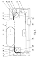
- The idea of the invention is schematically shown in a sample Fig. 1, and individual options of the invented method are explained by the described examples.
- Conveyor 1 is located between producing machine and receiving device - not shown in the Fig. 1, particularly variable-volume buffer-type magazine of a type "first in - first out", for example magazine described of Polish patent No.
PL 186270 transport sector 2 conveyingmulti-layered stack 3 of rod-shaped elements 4 andreturn sector 5. In-feed station 6 is located at the in-feed part of thetransport sector 2, and out-feed section 7 is located at the out-feed part of thetransport sector 2. Conveyor 1. consists ofidentical segments 8, whereas one of thesegments 8, differently marked, is used as acalibration element 9. In-feed counter 10 and in-feed detector 11 reading information from the conveyor 1 within area of co-operation withdiscs 12 equipped withscale 13 which corresponds to a distance betweensegments 8, are located within the in-feed station 6; whereas, control-measuring device 14 is installed before the in-feed station 6. Out-feed counter 15 and out-feed detector 16 reading information from the conveyor 1 within the area of co-operation with scaleddisc 17 equipped withscale 18 corresponding tosegments 8, are located within the out-feed station 7; whereas, rejectingdevice 19 is installed behind out-feed station 7, for example valve-type device described inPolish patent application No. P-347731 feed counter 10 and out-feed counter 15, in-feed detector 11 and out-feed detector 16, control-measuring device 14 and rejectingdevice 19, are coupled with thecontrol system 20. - Rod-
shaped elements 4 manufactured by producing machine are transferred in form ofmulti-layered stack 3 totransport sector 2 of the variable-length conveyor 1. Control-measuring device 14 takes, with assumed frequency, samples ofelements 4 for quality test. In case when adefective element 4 is detected, information about its defectiveness is assigned to theelement 4 and sent to themachine control system 20. If one of the sequent tests made by the control-measuring device 14 proves that theelement 4 is no longer defective, that is assumed as a final part of portion ofdefective elements 4, and appropriate information is sent to thecontrol system 20. Information about defectiveness is assigned to thedefective element 4 by means of appropriate marking of theelement 4, after it leaves the control-measuring device 14.Stack 3 ofelements 4 moving along the conveyor 1 is tracked by in-feed counter 10 located within in-feed station 6 and by out-feed counter 15 located within out-feed station 7, and signals informing about presence of initial and final part of thedefective elements 4 are suitably processed in themachine control system 20 and then transferred to the rejectingdevice 19 in order to remove the elements from movingstack 3, whereas rejecting device removes allelements 4 located on the conveyor 1, since quality measurement is made by the control-measuring device14, prior to measurement detecting thedefective element 4, up to thelast element 4, before theproper quality element 4 is detected. - Manufactured by the producing machine rod-
shaped elements 4 are transferred in form ofmulti-layered stack 3 intotransport sector 2 of the variable-length conveyor 1. Control-measuring device 14 takes, with assumed frequency, samples ofelements 4 for quality test. When adefective element 4 is detected, the information about defectiveness is assigned tosegment 8 of the conveyor 1, whereelement 4 is located, whereas, the conveyor is divided into finite number ofidentical segments 8. If one on sequent tests made by the control-measuring device 14 proves that theelement 4 is no longer defective, it means that this is the final part of the portion of defective elements, and information about this fact is sent to controlsystem 20. Eachsegment 8 is electronically marked, for example with a bar code allowing identification of thesegment 8 by in-feed counter 10 located within in-feed station 6, and by out-feed counter 15 located within out-feed station 7. Signals about appearance ofsegments 8 corresponding to initial and final part of the portion ofdefective elements 4 are processed in themachine control system 20 and sent to rejectingdevice 19 in order to remove movingstack 3, whereas, rejectingdevice 19 removes allelements 4 which are located on the conveyor 1, since quality control measurement made by control-measuring device 14, prior to measurement detectingdefective element 4, up to thelast element 4, beforeproper element 4, is detected. - Manufactured by the producing machine rod-
shaped elements 4 are transferred in form ofmulti-layered stack 3 into thetransport sector 2 of the variable-length conveyor 1. Control-measuring device 14, with assumed frequency, takes samples ofelements 4 for quality test. When adefective element 4 is detected, the information about defectiveness is assigned tosegment 8 of the conveyor 1, whereelement 4 is located, whereas, the conveyor is divided into finite number ofidentical segments 8. If one on sequent tests made by the control-measuring device 14 proves that theelement 4 is no longer defective, it means that this is the final part of the portion of defective elements, and information about this fact is sent to themachine control system 20. Tracing of the portion ofdefective elements 4 is made by means of counting the number of pulses corresponding tosegments 8 by in-feed counter 10 located within in-feed station 6, and by out-feed counter 15 located within out-feed station 7, whereas, synchronous correction of readings of thecounters feed station 6 and out-feed station 7, and corrected to real value signal corresponding to the first and lastdefective element 4 is sent to the rejectingdevice 19, which removes all rod-shaped elements located on the conveyor 1, since quality measurement made by control-measuring device 14, prior to measurement detectingdefective element 4 up to thelast element 4 before measurement detectingproper element 4. Co-operation of the conveyor 1 with in-feed station 6 and out-feed station 7 is slip-less. Meeting this condition is allowed by installation of similarly scaleddiscs feed station 6 and out-feed station 7, equipped withidentical scale segments 8 of the conveyor 1. Calibration of temporary length of the conveyor 1 is made by means of counting pulses by out-feed counter 15 located within out-feed station 7, in the period since the calibratedelement 9, detected by in-feed detector, enter in-feed station 6, and then comparing the number of really counted pulses with theoretical number of pulses corresponding to temporary length of the conveyor 1 withintransport sector 2, stored within themachine control system 20, whereas, if the mentioned numbers of pulses - real and theoretical - are not identical at the moment when the calibratingelement 9 is detected by out-feed detector 16 located within out-feed station 7, a reading error of initial and final part of portion ofdefective element 4 present on the conveyor 1 occurs, and error magnitude is determined by difference between theoretical number of pulses and number of really counted pulses.Control system 20 automatically corrects a number of pulses corresponding to temporary length of the conveyor 1, introducing the new corrected value as a theoretical number of pulses for temporary length of the conveyor 1, and in a case of the error repetition, machine operator is obliged to check the counters, whereas, constant number of pulses between calibration cycles is assigned to the same length of the conveyor 1. The calibration is made automatically and continuously, and each detecting of the calibratingelement 9 by in-feed detector 11 located within on-feed station 6 commences next calibration process. Signal announcing the initial part of portion ofdefective elements 4 delivered by control-measuring device 14 is assigned by themachine control system 20 to temporary length of the conveyor 1, and out-feed counter 15 located within out-feed station 7 commences counting pulses corresponding to number of pulses corresponding to temporary, theoretical length of the conveyor 1, whereas, total counting of the mentioned number of pulses indicates that portion ofdefective elements 4 reached out-feed station 7. Signal announcing that final part of portion ofdefective elements 4 is detected by control-measuring device 14, corresponding to the firstgood quality element 4, is sent to the machine control system, where the difference between number of pulses red by in-feed counter 10 located within in-feed station 6 and final part of portion of defective elements is determined, and mentioned number of pulses is counted by out-feed counter 15 located within out-feed station 7. - Within single production line, the mentioned options can be superimposed or they can be mutually complemented, moreover, there is a possibility to define, track and remove several different portions of rod-shaped
defective elements 4 located withintransport sector 2 of the variable-length conveyor 1.
Claims (18)
- Method of defining, tracing and removing of portion of defective, rod-shaped elements (4) being transported on a tobacco industry production line conveyor (1), particularly elements (4) manufactured by producing machine which are located on variable-length conveyor (1), within variable-volume buffer magazine of the type "first in - first out", which is located between producing machine and receiving device, where quality of the rod-shaped elements (4) is checked after they leave the producing machine but before they enter the receiving device, and the defective rod-shaped elements (4) are removed from the conveyor (1) within the area before they enter the receiving device, characterized in that the first and the last defective rod-shaped element (4) in a portion which is delivered to the in-feed station, carries assigned information about its defectiveness, and tracing of the moving portion carrying this information take place within the section from the control-measuring device (14) up to rejecting device (19), with use of in-feed counter (10) located within in-feed station (6) and out-feed counter (15) located within out-feed station (7), whereas signals corresponding to the information about initial and final part of a portion of defective elements (4), after processed by the machine control system (20), are sent to rejecting device (19), in order to remove only that portion of rod-shaped elements (4), which carries an information about its defectiveness.
- Method as in claim 1, characterized in that assigning the information about defectiveness to a defective, rod-shaped element (4) is made by means of physical marking of the mentioned element (4).
- Method as in claim 2, characterized in that marking of the first and the last defective element (4) takes place after the element (4) has already left the control-measuring device (14).
- Method as in claim 1 or 3, characterized in that in the rejecting device (19) all rod-shaped elements (4) being present on the conveyor (1) are removed from the moment of quality test made by the control-measuring device (14), prior to measurement which detects defective element (4), up to the last element (4) before the first proper element (4) is detected.
- Method as in claim 1, characterized in that assigning the information about defectiveness to a defective element (4) is made by assigning this element (4) to that segment (8) of the conveyor (1), which was the closest in a distance to the element (4) before of the element (4) was taken to measurement, whereas whole conveyor (1) is divided into finite number of identical segments (8).
- Method as in claim 5, characterized in that each segment (8) is marked with electronic record allowing identification of the segment (8) by in-feed counter (10) located within the in-feed station (6) and out-feed counter (15) located within the out-feed station (7).
- Method as in claim 6, characterized in that in rejecting device (19), all rod-shaped elements (4) being present on the conveyor (1) during the period from the measurement made by control-measuring device (14) preceding measurement detecting defective element (4) up to the last defective element (4), before the measurement which detects the first proper element (4).
- Method as in claim 5, characterized in that tracing of portion of defective elements (4) is made by means of counting the number of pulses corresponding to segments (8) with use of in-feed counter (10) located within in-feed station (6) and the out-feed counter (15) located within the out-feed station (7), whereas contemporary correction of the counters (10), (15) indication is made by means of the calibration of temporary length of the conveyor (1) section extending between in-feed (6) and out-feed station (7), and signal corrected into real value corresponding to the first and the last defective element (4) is sent to the rejecting device (19).
- Method as in claim 8, characterized in that in rejecting device (19), all rod-shaped elements (4) present on the conveyor (1) during a period from quality control measurement made by control-measuring device (14) preceding measurement of the defective element (4) up to the last element (4), before measurement detecting the defective element (4), are detected.
- Method as in claim 8, characterized in that calibration of temporary length of the conveyor (1) is made by means of counting the number of pulses by out-feed counter (15) within out-feed station (7) during a period from the calibrating element (9) enters the in-feed station (6), being detected by in-feed detector (11), and comparison of real and theoretical number of pulses corresponding to temporary conveyor (1) length, stored in the machine control system (20) memory, whereas if the mentioned numbers of pulses - real and theoretical - are not equal, when calibrating element (9) is detected by out-feed detector (16) within out-feed station (7), reading error of the initial/final position of portion of rod-shaped defective elements (4) occurs, and the magnitude of the error is defined by the difference between the theoretical number of pulses and number of pulses really counted.
- Method as in claim 9, characterized in that the control system (20) automatically makes a correction of the number of pulses corresponding to temporary conveyor (1) length by means of introducing new, corrected value being equivalent to theoretical number of pulses for temporary conveyor (1) length, thus in case of the error re-occurrence, checking of counters (10), (15) by the operating personnel is required.
- Method as in claim 11, characterized in that for the same conveyor (1) length a constant number of pulses between calibration cycles is assigned.
- Method as in claim 12, characterized in that calibration is conducted automatically and continuously, whereas each detection of calibrating element (9) by in-feed detector (11) within the in-feed station (6) commences the next calibration process.
- Method as in claim 13, characterized in that signal announcing initial part of the defective elements (4) portion which is delivered by the control-measuring device (14) is assigned within machine control system (20) to temporary, theoretical length of the conveyor (1), and out-feed counter (15) located within the out-feed station (7) starts counting pulses corresponding to number of pulses of temporary, theoretical length of the conveyor (1), whereas total number of mentioned pulses indicates that the initial part of defective elements (4) reached the out-feed station (7).
- Method as in claim 14, characterized in that signal announcing the final part of the portion of defective elements (4) sent from the control-measuring device (14) is then transferred into the machine control system (20), where a difference between initial and final parts of the defective elements (4) red by the in-feed counter (10) located within the in-feed station (6) is defined, and mentioned number of pulses is counted by out-feed counter (15) located within out-feed station (7).
- Method as in claim 8, characterized in that co-operation of the conveyor (1) with the in-feed station (6) and out-feed station (7) is slip-less.
- System which allows defining, tracing and removing the portion of defective rod-shaped elements (4) from the conveyor (1) installed within the tobacco industry production line, particularly elements (4) manufactured by the producing machine located on variable-length conveyor (1), within variable-volume buffer magazine of the type "first in - first out" located between producing machine and receiving device, equipped with control-measuring device (14) installed also within the zone between producing machine and receiving device, including rejecting device (19) installed before the receiving device, whereas control-measuring device (14) and rejecting device (19) are coupled with the machine control system (20), characterized in that within the area of transport sector (2) of the conveyor (1), in-feed station (6) comprising in-feed counter (10) and in-feed detector (11) is located at the side of producing machine, whereas out-feed station (7) comprising of out-feed counter (15) and out-feed detector (16) is located at the side of the receiving device, whereas conveyor (1) consists of identical segments (8), moreover, conveyor (1) is equipped with calibrating element (9), while in-feed counter (10) and in-feed detector (11) located within in-feed station (6) and out-feed counter (15) and out-feed detector (16) located within out-feed station (7), are coupled with the machine control system (20).
- System as in claim 17, characterized in that calibrating element (9) creates distinctively marked segment (8) of the conveyor (1).
Applications Claiming Priority (2)
| Application Number | Priority Date | Filing Date | Title |
|---|---|---|---|
| PL363674A PL198848B1 (en) | 2003-11-24 | 2003-11-24 | Method for identifying, tracking and removing the sub-standard batches of bar-like elements transported on the production line conveyor used in tobacco industry as well as system designed to identify, track and remove the sub-standard batches of bar-like |
| PCT/PL2004/000093 WO2005049235A1 (en) | 2003-11-24 | 2004-11-22 | Method of defining, tracing and removing of the portion of defective rod-shaped elements transported by tobacco industry production line conveyor and a system which allows defining, tracing and removing of the portion of defective rod-shaped elements from the conveyor at tobacco industry production line |
Publications (2)
| Publication Number | Publication Date |
|---|---|
| EP1720665A1 EP1720665A1 (en) | 2006-11-15 |
| EP1720665B1 true EP1720665B1 (en) | 2008-01-09 |
Family
ID=34617764
Family Applications (1)
| Application Number | Title | Priority Date | Filing Date |
|---|---|---|---|
| EP04800233A Ceased EP1720665B1 (en) | 2003-11-24 | 2004-11-22 | Method of defining, tracing and removing of the portion of defective rod-shaped elements transported by tobacco industry production line conveyor and a system which allows defining, tracing and removing of the portion of defective rod-shaped elements from the conveyor at tobacco industry production line |
Country Status (4)
| Country | Link |
|---|---|
| EP (1) | EP1720665B1 (en) |
| DE (1) | DE602004011268T2 (en) |
| PL (1) | PL198848B1 (en) |
| WO (1) | WO2005049235A1 (en) |
Families Citing this family (5)
| Publication number | Priority date | Publication date | Assignee | Title |
|---|---|---|---|---|
| ITBO20040119A1 (en) † | 2004-02-27 | 2004-05-27 | Gd Spa | VARIABLE CAPACITY FIFO WAREHOUSE WITH EXPULSION STATION |
| DE102004021440A1 (en) † | 2004-04-28 | 2005-11-24 | Hauni Maschinenbau Ag | Method and system for tracking product data of a product mass flow in a transport line of the tobacco processing industry |
| CN105728334B (en) * | 2016-03-28 | 2017-12-15 | 嵊州北航投星空众创科技有限公司 | Automatic sorting machine for flat sticks |
| CN111820452A (en) * | 2020-07-15 | 2020-10-27 | 广东中烟工业有限责任公司 | A device for detecting and rejecting cigarette tipping paper offset for cigarette making machines |
| CN114343233B (en) * | 2022-01-21 | 2024-05-03 | 江苏中烟工业有限责任公司 | Starting control system and control method for rubbing device of cigarette tipping machine |
Family Cites Families (6)
| Publication number | Priority date | Publication date | Assignee | Title |
|---|---|---|---|---|
| DE3211111A1 (en) * | 1981-04-14 | 1982-10-28 | Hauni-Werke Körber & Co KG, 2050 Hamburg | Method and apparatus for testing and isolating rod-shaped articles in the tobacco processing industry |
| JPH0628585B2 (en) * | 1983-06-03 | 1994-04-20 | ケルベル・アクチエンゲゼルシヤフト | Method and apparatus for detecting the presence or absence of defects in rod-shaped articles in the tobacco processing industry |
| PL186270B1 (en) * | 1998-03-02 | 2003-12-31 | Int Tobacco Machinery Poland | Variable-capacity buffer magazine for feeding elongated rod-like objects |
| ITBO20000577A1 (en) * | 2000-10-03 | 2002-04-03 | Gd Spa | AUTOMATIC MACHINE |
| PL196117B1 (en) * | 2001-05-25 | 2007-12-31 | Int Tobacco Machinery Poland | Method of diciding into several streams a multiple-layer stack of moving rod-like elements and valve-type dividing device therefor |
| DE10216069A1 (en) * | 2002-04-11 | 2003-10-23 | Hauni Maschinenbau Ag | Method and device for acting on articles of the tobacco processing industry |
-
2003
- 2003-11-24 PL PL363674A patent/PL198848B1/en unknown
-
2004
- 2004-11-22 DE DE602004011268T patent/DE602004011268T2/en not_active Expired - Lifetime
- 2004-11-22 WO PCT/PL2004/000093 patent/WO2005049235A1/en not_active Ceased
- 2004-11-22 EP EP04800233A patent/EP1720665B1/en not_active Ceased
Also Published As
| Publication number | Publication date |
|---|---|
| WO2005049235A1 (en) | 2005-06-02 |
| PL363674A1 (en) | 2005-05-30 |
| PL198848B1 (en) | 2008-07-31 |
| WO2005049235B1 (en) | 2005-08-04 |
| DE602004011268T2 (en) | 2009-01-02 |
| DE602004011268D1 (en) | 2008-02-21 |
| EP1720665A1 (en) | 2006-11-15 |
Similar Documents
| Publication | Publication Date | Title |
|---|---|---|
| EP1830179B1 (en) | A method and apparatus for determining one or more physical properties of a rolled smoking article or filter rod | |
| US8459092B2 (en) | Checkweigher performance validation | |
| EP3172976B1 (en) | A method and a system for production of rod-shaped articles | |
| JP6193916B2 (en) | Injection molding system | |
| EP3259191B1 (en) | A detection system for detecting and determining an integrity of pharmaceutical/parapharmaceutical articles | |
| JP4991394B2 (en) | Sorting device | |
| EP3387919B1 (en) | Method and system for determining the track of origin of products of the tobacco processing industry, cigarette inspection station | |
| EP3175210B1 (en) | Leak detection system | |
| JPS6039555A (en) | Device for putting defect on rapid moving band material or selecting defective piece of material | |
| EP2243384A1 (en) | Method and device for testing the quality of filter rods with capsules | |
| JP2004097226A (en) | Method for measuring length and/or diameter of virgulate filter and system therefor | |
| EP3654275A1 (en) | Method and system for the automatic measuring of physical and dimensional parameters of multi-segment articles | |
| DE102016122632A1 (en) | Device for separating an article | |
| EP1720665A1 (en) | Method of defining, tracing and removing of the portion of defective rod-shaped elements transported by tobacco industry production line conveyor and a system which allows defining, tracing and removing of the portion of defective rod-shaped elements from the conveyor at tobacco industry production line | |
| DE602004004249T2 (en) | METHOD FOR DETECTING AND REMOVING INCORRECT CIGARETTES | |
| EP3384788B1 (en) | Apparatus and method for rejection of defective rod-like articles from a mass flow of rod-like articles of the tobacco industry | |
| EP1099388A2 (en) | Cigarette testing | |
| WO2018050427A1 (en) | Method and apparatus for sorting disc-shaped objects | |
| EP2159176A1 (en) | Measuring body for recognising sources of disturbances within a supply system for tobacco products | |
| EP4047329C0 (en) | METHOD AND DEVICE FOR CHECKING THE WEIGHING ACCURACY OF A SCALE INTEGRATED INTO A CONVEYOR LINE DURING OPERATION | |
| JPS63143111A (en) | Conveyance control device for vulcanization finished tire | |
| CN117396404A (en) | Filling machine packaging waste management | |
| WO1989007083A1 (en) | Tablet alignment apparatus | |
| EP0577950B1 (en) | Method for inspecting the volume of plastic bottles and device for carrying out this method | |
| JPH0587535A (en) | Method and device for measuring smoking article |
Legal Events
| Date | Code | Title | Description |
|---|---|---|---|
| PUAI | Public reference made under article 153(3) epc to a published international application that has entered the european phase |
Free format text: ORIGINAL CODE: 0009012 |
|
| 17P | Request for examination filed |
Effective date: 20060710 |
|
| AK | Designated contracting states |
Kind code of ref document: A1 Designated state(s): DE GB IT |
|
| DAX | Request for extension of the european patent (deleted) | ||
| RBV | Designated contracting states (corrected) |
Designated state(s): DE GB IT |
|
| GRAP | Despatch of communication of intention to grant a patent |
Free format text: ORIGINAL CODE: EPIDOSNIGR1 |
|
| GRAS | Grant fee paid |
Free format text: ORIGINAL CODE: EPIDOSNIGR3 |
|
| GRAA | (expected) grant |
Free format text: ORIGINAL CODE: 0009210 |
|
| AK | Designated contracting states |
Kind code of ref document: B1 Designated state(s): DE GB IT |
|
| REG | Reference to a national code |
Ref country code: GB Ref legal event code: FG4D |
|
| REF | Corresponds to: |
Ref document number: 602004011268 Country of ref document: DE Date of ref document: 20080221 Kind code of ref document: P |
|
| PLBE | No opposition filed within time limit |
Free format text: ORIGINAL CODE: 0009261 |
|
| STAA | Information on the status of an ep patent application or granted ep patent |
Free format text: STATUS: NO OPPOSITION FILED WITHIN TIME LIMIT |
|
| 26N | No opposition filed |
Effective date: 20081010 |
|
| PGFP | Annual fee paid to national office [announced via postgrant information from national office to epo] |
Ref country code: DE Payment date: 20201119 Year of fee payment: 17 Ref country code: GB Payment date: 20201120 Year of fee payment: 17 Ref country code: IT Payment date: 20201124 Year of fee payment: 17 |
|
| REG | Reference to a national code |
Ref country code: DE Ref legal event code: R119 Ref document number: 602004011268 Country of ref document: DE |
|
| GBPC | Gb: european patent ceased through non-payment of renewal fee |
Effective date: 20211122 |
|
| PG25 | Lapsed in a contracting state [announced via postgrant information from national office to epo] |
Ref country code: GB Free format text: LAPSE BECAUSE OF NON-PAYMENT OF DUE FEES Effective date: 20211122 Ref country code: DE Free format text: LAPSE BECAUSE OF NON-PAYMENT OF DUE FEES Effective date: 20220601 |
|
| PG25 | Lapsed in a contracting state [announced via postgrant information from national office to epo] |
Ref country code: IT Free format text: LAPSE BECAUSE OF NON-PAYMENT OF DUE FEES Effective date: 20211122 |