EP1719924A1 - Thermally insulated sandwich type joint structure - Google Patents
Thermally insulated sandwich type joint structure Download PDFInfo
- Publication number
- EP1719924A1 EP1719924A1 EP20050256805 EP05256805A EP1719924A1 EP 1719924 A1 EP1719924 A1 EP 1719924A1 EP 20050256805 EP20050256805 EP 20050256805 EP 05256805 A EP05256805 A EP 05256805A EP 1719924 A1 EP1719924 A1 EP 1719924A1
- Authority
- EP
- European Patent Office
- Prior art keywords
- composite
- outer face
- splice plate
- reduced thickness
- core panel
- Prior art date
- Legal status (The legal status is an assumption and is not a legal conclusion. Google has not performed a legal analysis and makes no representation as to the accuracy of the status listed.)
- Granted
Links
Images
Classifications
-
- F—MECHANICAL ENGINEERING; LIGHTING; HEATING; WEAPONS; BLASTING
- F16—ENGINEERING ELEMENTS AND UNITS; GENERAL MEASURES FOR PRODUCING AND MAINTAINING EFFECTIVE FUNCTIONING OF MACHINES OR INSTALLATIONS; THERMAL INSULATION IN GENERAL
- F16B—DEVICES FOR FASTENING OR SECURING CONSTRUCTIONAL ELEMENTS OR MACHINE PARTS TOGETHER, e.g. NAILS, BOLTS, CIRCLIPS, CLAMPS, CLIPS OR WEDGES; JOINTS OR JOINTING
- F16B5/00—Joining sheets or plates, e.g. panels, to one another or to strips or bars parallel to them
- F16B5/01—Joining sheets or plates, e.g. panels, to one another or to strips or bars parallel to them by means of fastening elements specially adapted for honeycomb panels
-
- Y—GENERAL TAGGING OF NEW TECHNOLOGICAL DEVELOPMENTS; GENERAL TAGGING OF CROSS-SECTIONAL TECHNOLOGIES SPANNING OVER SEVERAL SECTIONS OF THE IPC; TECHNICAL SUBJECTS COVERED BY FORMER USPC CROSS-REFERENCE ART COLLECTIONS [XRACs] AND DIGESTS
- Y10—TECHNICAL SUBJECTS COVERED BY FORMER USPC
- Y10T—TECHNICAL SUBJECTS COVERED BY FORMER US CLASSIFICATION
- Y10T428/00—Stock material or miscellaneous articles
- Y10T428/19—Sheets or webs edge spliced or joined
- Y10T428/192—Sheets or webs coplanar
- Y10T428/197—Sheets or webs coplanar with noncoplanar reinforcement
-
- Y—GENERAL TAGGING OF NEW TECHNOLOGICAL DEVELOPMENTS; GENERAL TAGGING OF CROSS-SECTIONAL TECHNOLOGIES SPANNING OVER SEVERAL SECTIONS OF THE IPC; TECHNICAL SUBJECTS COVERED BY FORMER USPC CROSS-REFERENCE ART COLLECTIONS [XRACs] AND DIGESTS
- Y10—TECHNICAL SUBJECTS COVERED BY FORMER USPC
- Y10T—TECHNICAL SUBJECTS COVERED BY FORMER US CLASSIFICATION
- Y10T428/00—Stock material or miscellaneous articles
- Y10T428/24—Structurally defined web or sheet [e.g., overall dimension, etc.]
- Y10T428/24149—Honeycomb-like
- Y10T428/24157—Filled honeycomb cells [e.g., solid substance in cavities, etc.]
-
- Y—GENERAL TAGGING OF NEW TECHNOLOGICAL DEVELOPMENTS; GENERAL TAGGING OF CROSS-SECTIONAL TECHNOLOGIES SPANNING OVER SEVERAL SECTIONS OF THE IPC; TECHNICAL SUBJECTS COVERED BY FORMER USPC CROSS-REFERENCE ART COLLECTIONS [XRACs] AND DIGESTS
- Y10—TECHNICAL SUBJECTS COVERED BY FORMER USPC
- Y10T—TECHNICAL SUBJECTS COVERED BY FORMER US CLASSIFICATION
- Y10T428/00—Stock material or miscellaneous articles
- Y10T428/24—Structurally defined web or sheet [e.g., overall dimension, etc.]
- Y10T428/24174—Structurally defined web or sheet [e.g., overall dimension, etc.] including sheet or component perpendicular to plane of web or sheet
-
- Y—GENERAL TAGGING OF NEW TECHNOLOGICAL DEVELOPMENTS; GENERAL TAGGING OF CROSS-SECTIONAL TECHNOLOGIES SPANNING OVER SEVERAL SECTIONS OF THE IPC; TECHNICAL SUBJECTS COVERED BY FORMER USPC CROSS-REFERENCE ART COLLECTIONS [XRACs] AND DIGESTS
- Y10—TECHNICAL SUBJECTS COVERED BY FORMER USPC
- Y10T—TECHNICAL SUBJECTS COVERED BY FORMER US CLASSIFICATION
- Y10T428/00—Stock material or miscellaneous articles
- Y10T428/249921—Web or sheet containing structurally defined element or component
- Y10T428/249923—Including interlaminar mechanical fastener
Definitions
- the present invention relates generally to structural joints in composite structures and, more particularly, to a uniquely configured composite joint that is specifically adapted to minimize transfer of heat across the composite joint such as between an exterior of the composite structure and an interior thereof.
- the unique arrangement of the composite joint also provides for an effective sealing of the interior of the composite structure such as may be required in a fuel tank of an aircraft.
- composite structures are typically comprised of composite panels which are constructed as inner and outer face sheet within which a core panel is sandwiched therebetween.
- the composite face sheets may be fabricated of any fiber reinforced resin matrix such as fiberglass or graphite epoxy.
- Core panel materials are typically foam or honeycomb construction. It is also well known that many aircraft integrate fuel tanks into the wing structure. The ability to control or prevent the flow of excess heat into the fuel tanks is important for the overall integrity, performance and safety of the aircraft. Such heat may be generated due to aerodynamic friction as well as due to radiation as may be generated by the sunlight on the aircraft's wing surfaces.
- Heat generated by aerodynamic friction on outer surfaces of joint areas of the aircraft may be somewhat mitigated by the use of countersunk fasteners. More specifically, it is common in the industry to employ mechanical fasteners having countersunk heads in joint areas to minimize the amount of aerodynamic drag that would otherwise be collected by protruding fastener heads. However, because most mechanical fasteners include a shank which extends from the exterior to the interior of the aircraft structure, the mechanical fastener provides a path by which thermal heat may readily pass into the interior.
- the control of heat flow through non-joint areas of the composite structures may be more easily controlled.
- thermal conductivity from the outer face sheet toward the inner face sheet may be controlled by reducing the radiative or conductive heat transfer through the core panel.
- core panels made of closed cell foams conductive heat transfer is made difficult due to the large number of small cells that the heat must cross in traveling from one face sheet to another face sheet, such as from an outer face sheet to an inner face sheet.
- honeycomb core panels both radiative and conductive heat transfer between the outer face sheet and the inner face sheet is much easier as most honeycomb cores include hollow cells which provide a direct path for heat flow.
- cell walls of honeycomb core panels provide a direct conductive heat path from the outer face sheet to the inner face sheet.
- many aircraft typically include removable access panels or doors which allow for inspection and or access to certain internal portions of the aircraft structure.
- fuel tanks in some aircraft may include removable panels that to allow for inspection of interior portions of the fuel tank.
- a plurality of mechanical fasteners are typically provided around the perimeter of the access panel. Unfortunately, heat is easily conducted through the shanks of such mechanical fasteners. The control of such heat flow to the fuel tank is of critical importance.
- the present invention specifically addresses the above-referenced needs associated with composite joints. More specifically, the present invention is a composite joint which minimizes heat conduction between an exterior and an interior of the composite joint.
- the composite joint of the present invention may be configured to limit heat conduction in a specified direction across the composite joint.
- the composite joint may be configured to limit heat conduction in a direction from the interior to the exterior of the composite joint such as may be desirable, for example, in retaining heat within a hot water tank located within a wing structure.
- the composite joint may be configured to limit heat conduction along a direction from external wing surfaces to the interior of the composite joint such as may be desirable, for example, in preventing heat buildup in a fuel tank located in the wing structure.
- the present invention may be configured as a composite joint and/or as a composite structure.
- the composite joint comprises a pair of adjoining composite panels and a primary splice plate.
- the primary splice plate is configured to connect the composite panels using at least one mechanical fastener extending through each of the composite panels and through the primary splice plate.
- the composite joint includes a layer of thermal barrier compound covering the primary splice plate. The thermal barrier compound may also extend beyond the primary splice plate and may partially overlap the inner face sheets of the adjoining composite panels.
- the present invention may further be configured as the composite structure wherein a continuous, uninterrupted section of a composite panel is included and which may itself include a constant thickness portion that transitions along ramp portions to a reduced thickness portion.
- a vertical web may be extended laterally inwardly from the reduced thickness portion for load distribution purposes and/or for partitioning an internal area.
- the arrangement of the composite structure of the present invention is substantially similar to the arrangement of the composite joint of the present invention with the main difference being that the composite joint includes two adjoining composite panels whereas the composite structure includes a single one of the composite panels.
- each of the composite panels includes opposing inner and outer face sheets sandwiching a core panel therebetween.
- the inner and outer face sheets may be constructed of a fiber reinforced matrix material such as fiberglass or graphite epoxy although any suitable material may be used.
- the core panel may be constructed of honeycomb material which typically has a plurality of aligned hexagonally cross-sectional shaped cells that extend from the inner face sheet to the outer face sheet.
- the honeycomb may be formed of aramid paper so as to have a reduced heat conducting capability although any material may be used.
- the core panel defines a generally constant thickness portion and a ramp portion along which the core panel tapers to a reduced thickness portion.
- the outer face sheets of the adjoining composite panels are locally thickened in the area of the core panel reduced thickness portion such that the overall thickness of the composite panel is substantially maintained therethroughout.
- the cells within the reduced thickness portions are filled with a filler material.
- the cells within the ramp portions and within the constant thickness portions are preferably filled with aerogel in order to reduce the amount of heat flux across the composite joint.
- the filler material may be an aerogel and/or thermal barrier compound and/or potting compound.
- the composite joint includes a primary splice plate which extends across the reduced thickness portions of the adjoining composite panels and may further include at least one secondary splice plate which is preferably sized and configured to be complimentary to the primary splice plate.
- the primary splice plate is sandwiched between the inner face sheets and a secondary splice plate.
- At least one mechanical fastener extends through the outer face sheet at its locally thickened area and into the reduced thickness portions of the core panel and passes through the inner face sheet before entering the primary and secondary splice plates.
- the mechanical fasteners terminate in a fastener receiver disposed against the secondary splice plate.
- a layer of thermal barrier compound preferably covers the primary splice plate as well as the fastener receivers and also preferably extends beyond the primary splice plate and downwardly along edges thereof to the inner face sheets of the composite panel.
- the thermal barrier compound may be installed as a paste or as preformed blocks so as to provide any thickness of thermal barrier compound.
- a coating of polysulfide sealant may be distributed along the inner face sheets and along the thermal barrier compound covering the primary splice plate and fastener receivers.
- a polysulfide sealant is a final coating which is applied after the application of the thermal barrier coating thereon.
- Such polysulfide sealant may provide a means for fluid sealant of the composite joint as well as provide an additional layer of insulated material.
- a composite joint 10 that is uniquely configured for minimizing heat conduction through mechanical fasteners 36 which interconnect the composite panels 12.
- the composite joint 10 is specifically configured to prevent heat transfer across the composite joint 10.
- the present invention may be configured as a composite joint as shown in Fig. 1 or as a composite structure as shown in Fig. 1a.
- the composite joint shown in Fig. 1 comprises a pair of adjoining composite panels and a primary splice plate.
- the composite joint 10 comprises the pair of adjoining composites panels, a primary splice plate, and at least one mechanical fastener 36 extending through each one of the composite panels 12 with a layer of thermal barrier compound 56 covering the primary splice plate 32
- the present invention may further be configured as the composite structure shown in Fig. la wherein a continuous, uninterrupted section of a composite panel may include an area wherein the composite panel includes a core panel having a constant thickness portion that tapers along a pair of ramp portions to a reduced thickness portion.
- a vertical web may be extended laterally inwardly from the inner face sheet at the reduced thickness portion for load distribution purposes and/or for partitioning an internal area.
- the arrangement of the composite structure of the present invention is substantially similar to the arrangement of the composite joint of the present invention with the main difference being that the composite joint includes two adjoining composite panels whereas the composite structure includes only a single one of the composite panels.
- the composite joint 10 comprises the pair of adjoining composite panels 12 which are shown disposed in side-by-side arrangement and are generally aligned with one another.
- each one of the composite panels 12 is comprised of an inner and outer face sheet 18, 20 with a core panel 22 sandwiched therebetween.
- the inner and outer face sheets 18, 20 are bonded to the core panel 22 and are typically constructed of a fiber reinforced matrix material such as fiberglass or graphite epoxy.
- the inner and outer face sheets 18, 20 may be constructed of any material and are not necessarily limited to a fiber reinforced resin material but may be fabricated of metallic material, a polymeric material or any other material suitable for the application.
- the inner and outer face sheets 16, 18 may be comprised of multiple layers of inner and outer face sheets 16, 18, respectively.
- the core panel 22 of the present invention has a generally constant thickness portion 28 and a pair of ramp portions 26 along which the core panel 22 tapers to a reduced thickness portion 30 thereof.
- the reduced thickness portions 30 are arranged to be in generally side-by-side arrangement with one another.
- the outer face sheets 20 of the adjoining composite panels 12 are locally thickened in the area of the core panel 22 of the reduced thickness portion 30.
- the outer face sheets 20 are thickened in this local area such that the overall composite panel thickness 14 is substantially maintained therethroughout.
- the core panel 22 may be constructed of any material having suitable mechanical properties such as suitable strength and stiffness characteristics for the given application.
- the core panels 22 are constructed generally of honeycomb material which, as is well known in the art, typically comprises a sheet of material having a plurality of aligned cells 24 each having a hexagonal cross-sectional shape and which are generally elongate and hollow and generally extend from the inner face sheet 18 to the outer face sheet 20.
- the cells 24 of the honeycomb are typically oriented to be generally orthogonal relative to the inner and outer face sheets 18, 20 although other orientations are contemplated.
- the honeycomb is formed of aramid paper so as to have a reduced heat conducting and capability.
- the honeycomb may be formed of any material including metallic material and/or polymeric material.
- aramid paper is preferred.
- the aramid paper may be an aramid fiber paper that is saturated with resin in order to produce a cell 24 structure having improved mechanical properties for the core panel 22.
- such aramid fiber paper advantageously provides reduced thermal conductivity properties which are more suitable for the present invention
- the cells 24 within the reduced thickness portions 30 of the core panel 22 are substantially filled with a filler material 54.
- the cells 24 within the ramp portions 26 and within the constant thickness portions 28 of the core panel 22 are preferably substantially filled with aerogel 60. Filling the cells 24 with filler material 54 and/or aerogel 60 reduces the amount of heat flux across the composite joint 10 from the outer face sheets 20 to the inner face sheets 18.
- the filler material 54 may be one of an aerogel 60 and/or thermal barrier compound 56 and/or potting compound 58 or any combination thereof.
- the filler material 54 prevents heat convection and radiation and reduces heat conduction between the outer face sheets 20 and the inner face sheets 18. In this manner, unwanted thermal buildup within the inner structure of the composite joint 10 is avoided.
- Aerogel 60 which may be used in the cells 24 of the ramp portions 26 and constant thickness portions 28 is a well known material and is utilized frequently in the aerospace industry. Aerogel 60 is generally a highly porous material which may be comprised of silicon and/or metal oxides and which has an extremely low density but which also has an extremely high internal surface area. For this reason, aerogel 60 has an extremely high load carrying capability which makes it ideal as a lightweight structural material for composites. Advantageously, the extremely high internal surface area of aerogel 60 also makes it ideal as a thermal barrier material 56. As was earlier mentioned, the aerogel 60 as used in the present invention may be a silica aerogel although other aerogels such as metal oxide aerogel may be used.
- the filler material 54 may be a thermal barrier compound 56 and, in this regard, the thermal barrier compound 56 may be any compound having heat insulating characteristics.
- a preferred thermal barrier compound 56 is one that is commonly referred to as FASTBLOCK, manufactured by Kirkhill-TA Company, Brea, California.
- FASTBLOCK utilizes a silicon based elastomer which also contains ceramic precursors that transition into thermally resistant ceramic material when exposed to high heat.
- the FASTBLOCK Due to its composition, the FASTBLOCK provides a stiff, low density coating which, upon exposure to extreme temperatures, becomes ceramic in order to reduce heat transfer therethrough.
- the thermal barrier compound 56 may alternatively be comprised of any silicon based ablative material or any other material that prevents high heat flux.
- FASTBLOCK may be a preferred thermal barrier compound 56 and more particularly, FASTBLOCK-800F may be a most preferred alternative in the family of FASTBLOCK products due to its viscous consistency which may enhance its application into the composite joint 10.
- Another preferred filler material 54 may be a potting compound 58 such as an epoxy microballoon matrix material.
- resin may be a better candidate for the potting compound.
- thermoset bismaleimide resin (BMI) may be a preferred resin for the potting compound.
- Other materials from which the thermal barrier compound 56 may be comprised include Nanogel, TEEK foam, polyurethane foam, polyvinylchloride (PVC) foam and Rohacell foam.
- Nanogel manufactured by Nanogel-Cabot Corporation, Alpharetta, Georgia, is a hydrophobic silica aerogel 60 which has nano-sized pores. Such fine pore structure of Nanogel provides superior thermal protection for the application described herein.
- TEEK Foam is a polyimide foam that is commercially known as SOLREX and is available from Sordal of Holland, Michigan. TEEK Foam is a very low density, closed cell which retains its structural integrity under extreme temperatures. Such TEEK Foam may be directly installed on a structural system or injected into the cells 24 of honeycomb core panel 22 in a timely and efficient manner.
- Polyurethane foam may also be used for filling cells 24 of the honeycomb core panel 22.
- Airex a PVC foam manufactured by Alcan Baltek Corporation, Northvale, New Jersey is a lightweight closed cell foam that also offers excellent thermal resistance at elevated temperatures and which exhibits high stiffness and strength characteristics for its low weight.
- Rohacell is a polymethacrylimide foam that is a closed cell rigid foam which exhibits favorable thermal resistance at elevated temperatures.
- the filler material 54 Regardless of which type of filler material 54 is chosen to fill the cells 24 in the reduced thickness portions 30 of the core panels 22, the filler material 54 preferably has favorable thermal resistance properties which are maintainable at elevated temperatures.
- the composite joint 10 of the present invention may further include the primary splice plate 32 which extends across the reduced thickness portions 30 of the adjoining composite panels 12.
- the primary splice plate 32 has a width which is approximately equivalent to that of the combined width of the reduced thickness portions 30 for the adjoining composite panels 12.
- an appropriate surface area of the primary splice plate 32 is provided.
- the composite joint 10 may further include at least one secondary splice plate 34 which is preferably sized and configured to be complimentary to the primary splice plate 32 as is shown in Figure 1.
- the secondary splice plate 34 may be of any size and any shape.
- the primary splice plate 32 is preferably sandwiched between the inner face sheets 18 and the secondary splice plate 34.
- the secondary splice plate 34 may be comprised of a stack of secondary splice plates 34.
- the inner ones of the secondary splice plates 34 are preferably sandwiched between a primary splice plate 32 and the outermost one of the secondary splice plates 34.
- a plurality of primary splice plates 32 may also be provided wherein the primary splice plates 32 may have an increased thickness relative to a thickness of the secondary splice plates 34.
- the primary splice plates 32 and/or the secondary splice plates 34 may be provided in any width such as that which is described above wherein the primary splice plates 32 have a width which is approximately equivalent to the combined width of the reduced thickness portions 30 of the core panels 22.
- the primary splice plate 32 may extend into the constant thickness and/or ramp portions 26 of the core panels 22.
- the composite joint 10 further includes at least one mechanical fastener 36 which extends through the outer face sheet 20 at its locally thickened area and into the reduced thickness portions 30 of the core panel 22 and passing through the inner face sheet 18 of each one of the adjoining composite panels 12 before entering the primary splice plate 32. If a secondary splice plate 34 or a plurality of secondary splice plates 34 are provided, it is further contemplated that the mechanical fastener 36 will extend therethrough. As shown in the Figure, the mechanical fasteners 36 may be arranged in two rows in each one of the composite panels 12. However, the mechanical fasteners 36 may be provided in any number of rows on each side of the composite panels 12. Furthermore, the mechanical fasteners 36 may be provided in any arrangement other than rows such as in a staggered arrangement.
- each one of the mechanical fasteners 36 terminates in a fastener receiver 42 which is preferably disposed against the secondary splice plate.
- the fastener receiver 42 may be configured as a dome nut 44 such as a nut plate device which may be permanently affixed to the primary splice plate 32.
- the dome nut 44 may be configured to provide sealing of the shank 40 of the mechanical fastener 36 against the interior volume of the composite joint 10. More specifically, in scenarios wherein the interior of the composite joint 10 is a portion of a fuel tank integrated into a wing structure, the dome nut 44 may provide sealing against fluids so as to prevent leakage of the fluid through the fastener receiver 42 and out into the exterior of the fuel tank.
- the mechanical fastener 36 may be configured as a screw or a bolt and is preferably installed countersunk into the outer face sheets 20 in order to minimize their dynamic friction which may increase heat transfer through the shank 40.
- the fastener head 38 of the mechanical fasteners 36 may be countersunk into the outer face sheets 20.
- the composite joint 10 of the present invention may optionally include a vertical web 48 which extends laterally inwardly from the inner face sheet 18 of the adjoining composite panels 12 as is shown in the Figure.
- the vertical web 48 may include opposing web faces 50.
- the layer of thermal barrier compound 56 which preferably covers the primary splice plate 32 as well as the fastener receivers 42 and which also preferably extends beyond the primary splice plate 32 and downwardly along edges thereof to the inner face sheets 18 of the composite panel 12.
- the thermal barrier compound 56 may be provided at a level which is slightly above the level of the fastener receivers 42 as is shown on the right hand side of the composite joint 10 in Figure 1.
- the thermal barrier compound 56 may be provided in a relatively thin layer covering the primary splice plate 32 and the profile of the fastener receivers 42 as is shown on the left hand side of the composite joint 10 in Figure 1.
- the thermal barrier compound 56 may be extended along the opposing web faces 50 of the vertical web 48 so as to provide improved thermal resistance thereagainst.
- the thermal barrier compound 56 may be installed as a paste or as preformed blocks which are glued or otherwise adhered to the primary splice plate 32. If provided in paste form, it is contemplated that the thermal barrier compound 56 may be troweled onto the primary splice plate 32 and over the fastener receivers 42 at the desired thickness. Likewise, the paste of the thermal barrier compound 56 may be troweled along the web faces 50 of the vertical web 48 so as to provide a continuous layer of thermal barrier compound 56 between the primary splice plate 32 and the vertical web 48.
- the thermal barrier compound 56 may be installed by adhering the preformed blocks to the primary splice plate 32 and/or the web faces 50. Likewise, preformed blocks of the thermal barrier compound 56 may be installed against the ramp portions 26. In this manner, the thermal barrier compound 56 may be provided in any thickness and may be installed in any manner so as to provide the requisite amount of thermal resistance to prevent conduction of heat into the interior of the composite joint 10.
- the composite joint 10 of the present invention may further comprise a coating of polysulfide sealant 52 which may be extended or covered along the inner face sheets 18 and along a thermal barrier compound 56 covering the primary splice plate 32 and fastener receivers 42.
- a polysulfide sealant 52 is a final coating which is applied after the application of the thermal barrier coating thereon.
- Such polysulfide sealant 52 may provide an additional layer of insulated material.
- polysulfide sealant 52 is installed in order to provide an additional sealant against leakage of fluid.
- polysulfide sealants are commonly used in fuel tank sealing applications. It is contemplated that a polysulfide compound may be provided which is including microballoon materials in order to reduce density thereof and reduce weight.
- the composite joint 10 of the present invention may utilize any sealant which may provide the required fluid leakage prevention.
- the present invention may be configured as the composite structure including a continuous, uninterrupted section of composite panel is included and which may itself include a core panel having a pair of constant thickness portions that transitions along ramp portions to a reduced thickness portion. As shown in Fig. 1a, the vertical web may be extended laterally inwardly from the inner face sheet at the reduced thickness portion.
- the arrangement of the composite structure of the present invention is substantially similar to the arrangement of the composite joint of the present invention with the main difference being that the composite joint includes two adjoining composite panels whereas the composite structure includes a single one of the composite panels.
- the composite structure includes the composite panel which defines a composite panel thickness and having at least one of the inner and outer face sheet sandwiching the core panel therebetween.
- the core panel defines a pair of the generally constant thickness portions and a pair of the ramp portions along which the core panel tapers to a reduced thickness portion.
- the outer face sheet is locally thickened in the area of the core panel reduced thickness portion such that the composite panel thickness is generally constant thereacross.
- the core panel includes the plurality of cells extending between the inner and outer face sheets. The cells within the reduced thickness portion are substantially filled with the filler material while the cells within the ramp portions and the constant thickness portions are substantially filled with aerogel.
Landscapes
- Engineering & Computer Science (AREA)
- General Engineering & Computer Science (AREA)
- Mechanical Engineering (AREA)
- Laminated Bodies (AREA)
Abstract
Description
- Not Applicable
- Not Applicable
- The present invention relates generally to structural joints in composite structures and, more particularly, to a uniquely configured composite joint that is specifically adapted to minimize transfer of heat across the composite joint such as between an exterior of the composite structure and an interior thereof. The unique arrangement of the composite joint also provides for an effective sealing of the interior of the composite structure such as may be required in a fuel tank of an aircraft.
- In many vehicles such as aircraft, the control of heat flow through certain structural areas is of critical importance in the design of the aircraft. More specifically, certain aircraft constructed of composite materials must be adapted to limit the flow of heat from an exterior of the aircraft to an interior thereof. Likewise, it is sometimes desirable to limit the flow of heat across a composite joint out of an interior portion of a composite structure. As is well known in the art, composite structures are typically comprised of composite panels which are constructed as inner and outer face sheet within which a core panel is sandwiched therebetween.
- The composite face sheets may be fabricated of any fiber reinforced resin matrix such as fiberglass or graphite epoxy. Core panel materials are typically foam or honeycomb construction. It is also well known that many aircraft integrate fuel tanks into the wing structure. The ability to control or prevent the flow of excess heat into the fuel tanks is important for the overall integrity, performance and safety of the aircraft. Such heat may be generated due to aerodynamic friction as well as due to radiation as may be generated by the sunlight on the aircraft's wing surfaces.
- Heat generated by aerodynamic friction on outer surfaces of joint areas of the aircraft may be somewhat mitigated by the use of countersunk fasteners. More specifically, it is common in the industry to employ mechanical fasteners having countersunk heads in joint areas to minimize the amount of aerodynamic drag that would otherwise be collected by protruding fastener heads. However, because most mechanical fasteners include a shank which extends from the exterior to the interior of the aircraft structure, the mechanical fastener provides a path by which thermal heat may readily pass into the interior.
- The control of heat flow through non-joint areas of the composite structures may be more easily controlled. For example, thermal conductivity from the outer face sheet toward the inner face sheet may be controlled by reducing the radiative or conductive heat transfer through the core panel. For core panels made of closed cell foams, conductive heat transfer is made difficult due to the large number of small cells that the heat must cross in traveling from one face sheet to another face sheet, such as from an outer face sheet to an inner face sheet. For honeycomb core panels, both radiative and conductive heat transfer between the outer face sheet and the inner face sheet is much easier as most honeycomb cores include hollow cells which provide a direct path for heat flow. Moreover, cell walls of honeycomb core panels provide a direct conductive heat path from the outer face sheet to the inner face sheet.
- Control of heat flow in joint areas is more difficult due to the heat path provided by mechanical fasteners. In such joint areas, heat conduction from the outer surface to the inner surface is a function of the cross sectional area of the shank of the mechanical fasteners. Unfortunately, because most mechanical fasteners are typically formed of highly conductive materials such as metallic material, heat is easily conducted through the shank. One attempt to minimize the amount of heat that transfers through the shanks of mechanical fasteners is to minimize the quantity of fasteners that are utilized in joint areas. Unfortunately, a certain amount of fasteners are required in order to adequately transfer structural loads.
- Furthermore, many aircraft typically include removable access panels or doors which allow for inspection and or access to certain internal portions of the aircraft structure. For example, fuel tanks in some aircraft may include removable panels that to allow for inspection of interior portions of the fuel tank. For such access panels, a plurality of mechanical fasteners are typically provided around the perimeter of the access panel. Unfortunately, heat is easily conducted through the shanks of such mechanical fasteners. The control of such heat flow to the fuel tank is of critical importance.
- As can be seen, there exists a need in the art for a composite joint wherein the conduction of heat through the shank of the mechanical fasteners to the interior of the structure is minimized. Furthermore, there exists a need in the art for a composite joint that allows for effective sealing in the interior of the composite joint such that fluids may be effectively contained. In addition, there exists a need in the art for a composite joint that provides for effective sealing under dynamic structural loading of the composite joint such as may be caused by aerodynamic forces. Finally, there exists a need in the art for a composite joint that is of simple construction in order to simplify manufacturability, installation and maintenance.
- The present invention specifically addresses the above-referenced needs associated with composite joints. More specifically, the present invention is a composite joint which minimizes heat conduction between an exterior and an interior of the composite joint. In this regard, the composite joint of the present invention may be configured to limit heat conduction in a specified direction across the composite joint. For example, the composite joint may be configured to limit heat conduction in a direction from the interior to the exterior of the composite joint such as may be desirable, for example, in retaining heat within a hot water tank located within a wing structure. Likewise, the composite joint may be configured to limit heat conduction along a direction from external wing surfaces to the interior of the composite joint such as may be desirable, for example, in preventing heat buildup in a fuel tank located in the wing structure.
- The present invention may be configured as a composite joint and/or as a composite structure. The composite joint comprises a pair of adjoining composite panels and a primary splice plate. The primary splice plate is configured to connect the composite panels using at least one mechanical fastener extending through each of the composite panels and through the primary splice plate. Importantly, the composite joint includes a layer of thermal barrier compound covering the primary splice plate. The thermal barrier compound may also extend beyond the primary splice plate and may partially overlap the inner face sheets of the adjoining composite panels.
- The present invention may further be configured as the composite structure wherein a continuous, uninterrupted section of a composite panel is included and which may itself include a constant thickness portion that transitions along ramp portions to a reduced thickness portion. A vertical web may be extended laterally inwardly from the reduced thickness portion for load distribution purposes and/or for partitioning an internal area. For purposes of the following discussion, the arrangement of the composite structure of the present invention is substantially similar to the arrangement of the composite joint of the present invention with the main difference being that the composite joint includes two adjoining composite panels whereas the composite structure includes a single one of the composite panels.
- In the composite joint, each of the composite panels includes opposing inner and outer face sheets sandwiching a core panel therebetween. The inner and outer face sheets may be constructed of a fiber reinforced matrix material such as fiberglass or graphite epoxy although any suitable material may be used. The core panel may be constructed of honeycomb material which typically has a plurality of aligned hexagonally cross-sectional shaped cells that extend from the inner face sheet to the outer face sheet. The honeycomb may be formed of aramid paper so as to have a reduced heat conducting capability although any material may be used.
- The core panel defines a generally constant thickness portion and a ramp portion along which the core panel tapers to a reduced thickness portion. The outer face sheets of the adjoining composite panels are locally thickened in the area of the core panel reduced thickness portion such that the overall thickness of the composite panel is substantially maintained therethroughout.
- The cells within the reduced thickness portions are filled with a filler material. The cells within the ramp portions and within the constant thickness portions are preferably filled with aerogel in order to reduce the amount of heat flux across the composite joint. The filler material may be an aerogel and/or thermal barrier compound and/or potting compound.
- The composite joint includes a primary splice plate which extends across the reduced thickness portions of the adjoining composite panels and may further include at least one secondary splice plate which is preferably sized and configured to be complimentary to the primary splice plate. The primary splice plate is sandwiched between the inner face sheets and a secondary splice plate.
- At least one mechanical fastener extends through the outer face sheet at its locally thickened area and into the reduced thickness portions of the core panel and passes through the inner face sheet before entering the primary and secondary splice plates. The mechanical fasteners terminate in a fastener receiver disposed against the secondary splice plate.
- A layer of thermal barrier compound preferably covers the primary splice plate as well as the fastener receivers and also preferably extends beyond the primary splice plate and downwardly along edges thereof to the inner face sheets of the composite panel. The thermal barrier compound may be installed as a paste or as preformed blocks so as to provide any thickness of thermal barrier compound.
- A coating of polysulfide sealant may be distributed along the inner face sheets and along the thermal barrier compound covering the primary splice plate and fastener receivers. In this regard, a polysulfide sealant is a final coating which is applied after the application of the thermal barrier coating thereon. Such polysulfide sealant may provide a means for fluid sealant of the composite joint as well as provide an additional layer of insulated material.
- These as well as other features of the present invention will become more apparent upon reference to the drawings wherein:
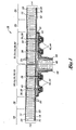
- Figure 1 is a cross-sectional view of a composite joint of the present invention illustrating a pair of adjoining composite panels interconnected by a primary splice plate and further illustrating a first configuration for a layer of thermal barrier compound on a left side of the composite joint and a second configuration for the layer of thermal barrier compound on a right side of the composite joint; and
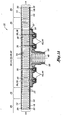
- Figure la is a cross sectional view of a composite structure in a further embodiment of the present invention and illustrating a composite panel interconnected to a vertical web and having mechanical fasteners extending through a primary splice plate with a layer of thermal barrier compound disposed thereon.
- Referring now to the drawings wherein the showings are for purposes of illustrating the present invention and not for purposes of limiting the same, provided is a composite joint 10 that is uniquely configured for minimizing heat conduction through
mechanical fasteners 36 which interconnect thecomposite panels 12. The composite joint 10 is specifically configured to prevent heat transfer across the composite joint 10. - It should be noted that the present invention may be configured as a composite joint as shown in Fig. 1 or as a composite structure as shown in Fig. 1a. The composite joint shown in Fig. 1 comprises a pair of adjoining composite panels and a primary splice plate. In its broadest sense, the composite joint 10 comprises the pair of adjoining composites panels, a primary splice plate, and at least one
mechanical fastener 36 extending through each one of thecomposite panels 12 with a layer of thermal barrier compound 56 covering theprimary splice plate 32 - The present invention may further be configured as the composite structure shown in Fig. la wherein a continuous, uninterrupted section of a composite panel may include an area wherein the composite panel includes a core panel having a constant thickness portion that tapers along a pair of ramp portions to a reduced thickness portion. A vertical web may be extended laterally inwardly from the inner face sheet at the reduced thickness portion for load distribution purposes and/or for partitioning an internal area. For purposes of the following discussion, the arrangement of the composite structure of the present invention is substantially similar to the arrangement of the composite joint of the present invention with the main difference being that the composite joint includes two adjoining composite panels whereas the composite structure includes only a single one of the composite panels.
- Referring first to Fig. 1, the composite joint 10 comprises the pair of adjoining
composite panels 12 which are shown disposed in side-by-side arrangement and are generally aligned with one another. As is well known in the art of composite construction, each one of thecomposite panels 12 is comprised of an inner andouter face sheet core panel 22 sandwiched therebetween. The inner andouter face sheets core panel 22 and are typically constructed of a fiber reinforced matrix material such as fiberglass or graphite epoxy. However, the inner andouter face sheets outer face sheets outer face sheets - Referring still to Figure 1, the
core panel 22 of the present invention has a generallyconstant thickness portion 28 and a pair oframp portions 26 along which thecore panel 22 tapers to a reduced thickness portion 30 thereof. As can be seen in Figure 1, the reduced thickness portions 30 are arranged to be in generally side-by-side arrangement with one another. In the present invention, theouter face sheets 20 of the adjoiningcomposite panels 12 are locally thickened in the area of thecore panel 22 of the reduced thickness portion 30. Theouter face sheets 20 are thickened in this local area such that the overallcomposite panel thickness 14 is substantially maintained therethroughout. - The
core panel 22 may be constructed of any material having suitable mechanical properties such as suitable strength and stiffness characteristics for the given application. For the composite joint 10 of the present invention, it is contemplated that thecore panels 22 are constructed generally of honeycomb material which, as is well known in the art, typically comprises a sheet of material having a plurality of alignedcells 24 each having a hexagonal cross-sectional shape and which are generally elongate and hollow and generally extend from theinner face sheet 18 to theouter face sheet 20. Furthermore, thecells 24 of the honeycomb are typically oriented to be generally orthogonal relative to the inner andouter face sheets - For the configuration of the present invention, it is contemplated that the honeycomb is formed of aramid paper so as to have a reduced heat conducting and capability. However, it is noted that the honeycomb may be formed of any material including metallic material and/or polymeric material. However, due to the relatively high heat conducting capability of metallic materials, aramid paper is preferred. The aramid paper may be an aramid fiber paper that is saturated with resin in order to produce a
cell 24 structure having improved mechanical properties for thecore panel 22. In addition, such aramid fiber paper advantageously provides reduced thermal conductivity properties which are more suitable for the present invention - Importantly, the
cells 24 within the reduced thickness portions 30 of thecore panel 22 are substantially filled with a filler material 54. However, thecells 24 within theramp portions 26 and within theconstant thickness portions 28 of thecore panel 22 are preferably substantially filled with aerogel 60. Filling thecells 24 with filler material 54 and/or aerogel 60 reduces the amount of heat flux across the composite joint 10 from theouter face sheets 20 to theinner face sheets 18. - For the reduced thickness portion 30 of the
core panel 22, the filler material 54 may be one of an aerogel 60 and/or thermal barrier compound 56 and/or potting compound 58 or any combination thereof. Importantly, the filler material 54 prevents heat convection and radiation and reduces heat conduction between theouter face sheets 20 and theinner face sheets 18. In this manner, unwanted thermal buildup within the inner structure of the composite joint 10 is avoided. - The aerogel 60 which may be used in the
cells 24 of theramp portions 26 andconstant thickness portions 28 is a well known material and is utilized frequently in the aerospace industry. Aerogel 60 is generally a highly porous material which may be comprised of silicon and/or metal oxides and which has an extremely low density but which also has an extremely high internal surface area. For this reason, aerogel 60 has an extremely high load carrying capability which makes it ideal as a lightweight structural material for composites. Advantageously, the extremely high internal surface area of aerogel 60 also makes it ideal as a thermal barrier material 56. As was earlier mentioned, the aerogel 60 as used in the present invention may be a silica aerogel although other aerogels such as metal oxide aerogel may be used. - The filler material 54 may be a thermal barrier compound 56 and, in this regard, the thermal barrier compound 56 may be any compound having heat insulating characteristics. A preferred thermal barrier compound 56, however, is one that is commonly referred to as FASTBLOCK, manufactured by Kirkhill-TA Company, Brea, California. FASTBLOCK utilizes a silicon based elastomer which also contains ceramic precursors that transition into thermally resistant ceramic material when exposed to high heat.
- Due to its composition, the FASTBLOCK provides a stiff, low density coating which, upon exposure to extreme temperatures, becomes ceramic in order to reduce heat transfer therethrough. The thermal barrier compound 56 may alternatively be comprised of any silicon based ablative material or any other material that prevents high heat flux. However, FASTBLOCK may be a preferred thermal barrier compound 56 and more particularly, FASTBLOCK-800F may be a most preferred alternative in the family of FASTBLOCK products due to its viscous consistency which may enhance its application into the composite joint 10.
- Another preferred filler material 54 may be a potting compound 58 such as an epoxy microballoon matrix material. However, for the particular application described herein, it is contemplated that resin may be a better candidate for the potting compound. In this regard, thermoset bismaleimide resin (BMI) may be a preferred resin for the potting compound. Other materials from which the thermal barrier compound 56 may be comprised include Nanogel, TEEK foam, polyurethane foam, polyvinylchloride (PVC) foam and Rohacell foam.
- Nanogel, manufactured by Nanogel-Cabot Corporation, Alpharetta, Georgia, is a hydrophobic silica aerogel 60 which has nano-sized pores. Such fine pore structure of Nanogel provides superior thermal protection for the application described herein. TEEK Foam is a polyimide foam that is commercially known as SOLREX and is available from Sordal of Holland, Michigan. TEEK Foam is a very low density, closed cell which retains its structural integrity under extreme temperatures. Such TEEK Foam may be directly installed on a structural system or injected into the
cells 24 ofhoneycomb core panel 22 in a timely and efficient manner. - Polyurethane foam may also be used for filling
cells 24 of thehoneycomb core panel 22. Likewise, Airex, a PVC foam manufactured by Alcan Baltek Corporation, Northvale, New Jersey is a lightweight closed cell foam that also offers excellent thermal resistance at elevated temperatures and which exhibits high stiffness and strength characteristics for its low weight. Rohacell is a polymethacrylimide foam that is a closed cell rigid foam which exhibits favorable thermal resistance at elevated temperatures. Regardless of which type of filler material 54 is chosen to fill thecells 24 in the reduced thickness portions 30 of thecore panels 22, the filler material 54 preferably has favorable thermal resistance properties which are maintainable at elevated temperatures. - The composite joint 10 of the present invention may further include the
primary splice plate 32 which extends across the reduced thickness portions 30 of the adjoiningcomposite panels 12. In this regard, it is contemplated that theprimary splice plate 32 has a width which is approximately equivalent to that of the combined width of the reduced thickness portions 30 for the adjoiningcomposite panels 12. By configuring theprimary splice plate 32 with such equivalent width, it is contemplated that an appropriate surface area of theprimary splice plate 32 is provided. - The composite joint 10 may further include at least one
secondary splice plate 34 which is preferably sized and configured to be complimentary to theprimary splice plate 32 as is shown in Figure 1. However, thesecondary splice plate 34 may be of any size and any shape. Theprimary splice plate 32 is preferably sandwiched between theinner face sheets 18 and thesecondary splice plate 34. As is shown in the Figure, however, thesecondary splice plate 34 may be comprised of a stack ofsecondary splice plates 34. In this regard, the inner ones of thesecondary splice plates 34 are preferably sandwiched between aprimary splice plate 32 and the outermost one of thesecondary splice plates 34. - A plurality of
primary splice plates 32 may also be provided wherein theprimary splice plates 32 may have an increased thickness relative to a thickness of thesecondary splice plates 34. Theprimary splice plates 32 and/or thesecondary splice plates 34 may be provided in any width such as that which is described above wherein theprimary splice plates 32 have a width which is approximately equivalent to the combined width of the reduced thickness portions 30 of thecore panels 22. However, it is also contemplated that theprimary splice plate 32 may extend into the constant thickness and/orramp portions 26 of thecore panels 22. - The composite joint 10 further includes at least one
mechanical fastener 36 which extends through theouter face sheet 20 at its locally thickened area and into the reduced thickness portions 30 of thecore panel 22 and passing through theinner face sheet 18 of each one of the adjoiningcomposite panels 12 before entering theprimary splice plate 32. If asecondary splice plate 34 or a plurality ofsecondary splice plates 34 are provided, it is further contemplated that themechanical fastener 36 will extend therethrough. As shown in the Figure, themechanical fasteners 36 may be arranged in two rows in each one of thecomposite panels 12. However, themechanical fasteners 36 may be provided in any number of rows on each side of thecomposite panels 12. Furthermore, themechanical fasteners 36 may be provided in any arrangement other than rows such as in a staggered arrangement. - As can be seen in the Figure, each one of the
mechanical fasteners 36 terminates in a fastener receiver 42 which is preferably disposed against the secondary splice plate. In this regard, the fastener receiver 42 may be configured as a dome nut 44 such as a nut plate device which may be permanently affixed to theprimary splice plate 32. The dome nut 44 may be configured to provide sealing of the shank 40 of themechanical fastener 36 against the interior volume of the composite joint 10. More specifically, in scenarios wherein the interior of the composite joint 10 is a portion of a fuel tank integrated into a wing structure, the dome nut 44 may provide sealing against fluids so as to prevent leakage of the fluid through the fastener receiver 42 and out into the exterior of the fuel tank. - The
mechanical fastener 36 may be configured as a screw or a bolt and is preferably installed countersunk into theouter face sheets 20 in order to minimize their dynamic friction which may increase heat transfer through the shank 40. In this regard, the fastener head 38 of themechanical fasteners 36 may be countersunk into theouter face sheets 20. The composite joint 10 of the present invention may optionally include avertical web 48 which extends laterally inwardly from theinner face sheet 18 of the adjoiningcomposite panels 12 as is shown in the Figure. Thevertical web 48 may include opposing web faces 50. - Further comprising the composite joint 10 is the layer of thermal barrier compound 56 which preferably covers the
primary splice plate 32 as well as the fastener receivers 42 and which also preferably extends beyond theprimary splice plate 32 and downwardly along edges thereof to theinner face sheets 18 of thecomposite panel 12. As in shown in Figure 1, the thermal barrier compound 56 may be provided at a level which is slightly above the level of the fastener receivers 42 as is shown on the right hand side of the composite joint 10 in Figure 1. Alternatively, the thermal barrier compound 56 may be provided in a relatively thin layer covering theprimary splice plate 32 and the profile of the fastener receivers 42 as is shown on the left hand side of the composite joint 10 in Figure 1. Furthermore, it is contemplated that the thermal barrier compound 56 may be extended along the opposing web faces 50 of thevertical web 48 so as to provide improved thermal resistance thereagainst. - It is contemplated that the thermal barrier compound 56 may be installed as a paste or as preformed blocks which are glued or otherwise adhered to the
primary splice plate 32. If provided in paste form, it is contemplated that the thermal barrier compound 56 may be troweled onto theprimary splice plate 32 and over the fastener receivers 42 at the desired thickness. Likewise, the paste of the thermal barrier compound 56 may be troweled along the web faces 50 of thevertical web 48 so as to provide a continuous layer of thermal barrier compound 56 between theprimary splice plate 32 and thevertical web 48. - If provided as preformed blocks, it is contemplated that the thermal barrier compound 56 may be installed by adhering the preformed blocks to the
primary splice plate 32 and/or the web faces 50. Likewise, preformed blocks of the thermal barrier compound 56 may be installed against theramp portions 26. In this manner, the thermal barrier compound 56 may be provided in any thickness and may be installed in any manner so as to provide the requisite amount of thermal resistance to prevent conduction of heat into the interior of the composite joint 10. - The composite joint 10 of the present invention may further comprise a coating of
polysulfide sealant 52 which may be extended or covered along theinner face sheets 18 and along a thermal barrier compound 56 covering theprimary splice plate 32 and fastener receivers 42. In this regard, apolysulfide sealant 52 is a final coating which is applied after the application of the thermal barrier coating thereon.Such polysulfide sealant 52 may provide an additional layer of insulated material. - Preferably,
polysulfide sealant 52 is installed in order to provide an additional sealant against leakage of fluid. For example, polysulfide sealants are commonly used in fuel tank sealing applications. It is contemplated that a polysulfide compound may be provided which is including microballoon materials in order to reduce density thereof and reduce weight. However, it is contemplated that the composite joint 10 of the present invention may utilize any sealant which may provide the required fluid leakage prevention. - Referring briefly to Fig. 1a, as was earlier mentioned, the present invention may be configured as the composite structure including a continuous, uninterrupted section of composite panel is included and which may itself include a core panel having a pair of constant thickness portions that transitions along ramp portions to a reduced thickness portion. As shown in Fig. 1a, the vertical web may be extended laterally inwardly from the inner face sheet at the reduced thickness portion. For purposes of the following discussion, the arrangement of the composite structure of the present invention is substantially similar to the arrangement of the composite joint of the present invention with the main difference being that the composite joint includes two adjoining composite panels whereas the composite structure includes a single one of the composite panels.
- Referring to Fig. 1a, the composite structure includes the composite panel which defines a composite panel thickness and having at least one of the inner and outer face sheet sandwiching the core panel therebetween. The core panel defines a pair of the generally constant thickness portions and a pair of the ramp portions along which the core panel tapers to a reduced thickness portion. As can be seen in Fig. 1a, the outer face sheet is locally thickened in the area of the core panel reduced thickness portion such that the composite panel thickness is generally constant thereacross. As was earlier mentioned, the core panel includes the plurality of cells extending between the inner and outer face sheets. The cells within the reduced thickness portion are substantially filled with the filler material while the cells within the ramp portions and the constant thickness portions are substantially filled with aerogel.
- Additional modifications and improvements of the present invention may also be apparent to those of ordinary skill in the art. Thus, the particular combination of parts described and illustrated herein is intended to represent only certain embodiments of the present invention, and is not intended to serve as limitations of alternative devices within the spirit and scope of the invention.
Claims (20)
- A composite structure, comprising:a composite panel defining a composite panel thickness and having at least one of an inner and outer face sheet sandwiching a core panel therebetween, the core panel defining a generally constant thickness portion and a ramp portion along which the core panel tapers to a reduced thickness portion, the outer face sheet being locally thickened in the area of the core panel reduced thickness portion such that the composite panel thickness is constant thereacross, the core panel including a plurality of cells extending between the inner and outer face sheets, the cells within the reduced thickness portion being substantially filled with a filler material, the cells within the ramp portion and constant thickness portion being substantially filled with aerogel;a primary splice plate extending across the reduced thickness portions;at least one mechanical fastener extending through the outer face sheet, the reduced thickness portion and the inner face sheet of the composite panel and passing through the primary splice plate; anda layer of themal barrier compound covering the primary splice plate.
- The composite structure of Claim 1 further comprising:a vertical web extending laterally inwardly from the inner face sheet at the reduced thickness portion, the vertical web having opposing web faces;wherein the layer of themal barrier compound extends along the opposing web faces.
- The composite structure of Claim 1 wherein:each one the mechanical fasteners terminates in a fastener receiver disposed against the primary splice plate;the layer of themal barrier compound covering the fastener receivers.
- The composite structure of Claim 1 wherein the filler material is one of aerogel and thermal barrier compound and potting compound.
- The composite structure of Claim 4 wherein:the aerogel is a silica aerogel;the thermal barrier compound is a silicone-based elastomer; andthe potting compound is an epoxy/microballoon material.
- The composite structure of Claim 1 wherein:the core panel is formed of honeycomb;each one of the cells being configured as an elongate hollow cell having a hexagonal cross section and being oriented generally orthogonally relative to the inner and outer face sheets.
- The composite structure of Claim 6 wherein the honeycomb is formed of aramid paper.
- The composite structure of Claim 1 wherein the inner and outer face sheets are formed of graphite/epoxy material.
- The composite structure of Claim 1 wherein the thermal barrier compound layer is formed at a constant thickness above a level of the fastener receivers.
- A composite joint, comprising:a pair of adjoining composite panels each defining a composite panel thickness and having at least one of an inner and outer face sheet sandwiching a core panel therebetween, the core panel defining a generally constant thickness portion and a ramp portion along which the core panel tapers to a reduced thickness portion, the composite panels being arranged such that the reduced thickness portions are adjacent to one another, the outer face sheet being locally thickened in the area of the core panel reduced thickness portion such that the composite panel thickness is constant thereacross, the core panel including a plurality of cells extending between the inner and outer face sheets, the cells within the reduced thickness portions being substantially filled with a filler material, the cells within the ramp portions and constant thickness portions being substantially filled with aerogel;a primary splice plate extending across the reduced thickness portions of the adjoining composite panels;at least one mechanical fastener extending through the outer face sheet, the reduced thickness portions and the inner face sheet of each one of the composite panels and passing through the primary splice plate; anda layer of themal barrier compound covering the primary splice plate.
- The composite joint of Claim 10 further comprising:at least one secondary splice plates sized and configured to be complementary to the primary splice plate;wherein:the primary splice plate is sandwiched between the outer face sheets and the secondary splice plate;the mechanical fastener extending through the outer face sheet, the reduced thickness portions and the inner face sheet of each one of the composite panels and passing through the primary and secondary splice plates.
- The composite joint of Claim 10 wherein the filler material is one of aerogel and thermal barrier compound and potting compound.
- The composite structure of Claim 12 wherein:the aerogel is a silica aerogel;the thermal barrier compound is a silicone-based elastomer; andthe potting compound is an epoxy/microballoon material.
- The composite joint of Claim 10 wherein each one of the adjoining composite panels the mechanical fasteners are arranged in two rows in each of the composite panels.
- The composite joint of Claim 10 wherein:each one the mechanical fasteners terminates in a fastener receiver disposed against the secondary splice plate;the layer of themal barrier compound covering the fastener receivers.
- The composite joint of Claim 10 wherein:the core panel is formed of honeycomb;each one of the cells being configured as an elongate hollow cell having a hexagonal cross section and being oriented generally orthogonally relative to the inner and outer face sheets.
- The composite joint of Claim 16 wherein the honeycomb is formed of aramid paper.
- The composite joint of Claim 10 wherein the inner and outer face sheets are formed of graphite/epoxy material.
- The composite joint of Claim 10 wherein the thermal barrier compound layer is formed at a constant thickness above a level of the fastener receivers.
- The composite joint of Claim 10 further comprising:a vertical web extending laterally inwardly from the inner face sheets of the adjoining composite panels, the vertical web having opposing web faces;wherein the layer of themal barrier compound extends along the opposing web faces.
Applications Claiming Priority (1)
| Application Number | Priority Date | Filing Date | Title |
|---|---|---|---|
| US11/122,468 US7291373B2 (en) | 2005-05-05 | 2005-05-05 | Thermally insulated structure—full depth sandwich joint concept |
Publications (2)
| Publication Number | Publication Date |
|---|---|
| EP1719924A1 true EP1719924A1 (en) | 2006-11-08 |
| EP1719924B1 EP1719924B1 (en) | 2008-05-21 |
Family
ID=36604203
Family Applications (1)
| Application Number | Title | Priority Date | Filing Date |
|---|---|---|---|
| EP20050256805 Expired - Lifetime EP1719924B1 (en) | 2005-05-05 | 2005-11-03 | Thermally insulated sandwich type joint structure |
Country Status (3)
| Country | Link |
|---|---|
| US (1) | US7291373B2 (en) |
| EP (1) | EP1719924B1 (en) |
| DE (1) | DE602005006979D1 (en) |
Cited By (3)
| Publication number | Priority date | Publication date | Assignee | Title |
|---|---|---|---|---|
| EP2409914A1 (en) * | 2010-07-23 | 2012-01-25 | BAE SYSTEMS plc | Aircraft thermal insulation |
| US9085350B2 (en) | 2010-01-20 | 2015-07-21 | Airbus Operations Limited | Aircraft wing cover comprising a sandwich panel and methods to manufacture and design the said wing cover |
| CN110181875A (en) * | 2019-06-27 | 2019-08-30 | 中素新科技有限公司 | Honeycomb sandwich board and its preparation method and application |
Families Citing this family (21)
| Publication number | Priority date | Publication date | Assignee | Title |
|---|---|---|---|---|
| US7837147B2 (en) | 2005-03-18 | 2010-11-23 | The Boeing Company | Systems and methods for reducing noise in aircraft fuselages and other structures |
| DE102006044093B4 (en) * | 2006-09-20 | 2009-01-22 | Airbus Deutschland Gmbh | Disk replacement to fill a window frame |
| US9511571B2 (en) | 2007-01-23 | 2016-12-06 | The Boeing Company | Composite laminate having a damping interlayer and method of making the same |
| US8016230B2 (en) * | 2007-05-11 | 2011-09-13 | The Boeing Company | Fastner-free primary structural joint for sandwich panels |
| ES2343047B1 (en) * | 2007-12-13 | 2011-06-14 | Airbus España, S.L. | ACOUSTICALLY ATTACHED AIRCRAFT FUSELAGE. |
| DE102008016104A1 (en) * | 2008-03-28 | 2009-10-08 | Airbus Deutschland Gmbh | Breathable aircraft fuselage |
| US8425710B2 (en) | 2009-03-13 | 2013-04-23 | The Boeing Company | Automated placement of vibration damping materials |
| US20110215202A1 (en) * | 2009-12-07 | 2011-09-08 | Global Aerosystems, Llc | Wing spar splice joint |
| CN102230489B (en) * | 2011-04-12 | 2012-09-26 | 哈尔滨工程大学 | T-shaped connection structure of composite material laminboard |
| US20120317984A1 (en) * | 2011-06-16 | 2012-12-20 | Dierberger James A | Cell structure thermal barrier coating |
| CA2842477C (en) * | 2011-08-17 | 2017-09-12 | B/E Aerospace, Inc | High-strength aircraft interior panel with embedded insert |
| US9140291B2 (en) * | 2012-09-28 | 2015-09-22 | The Boeing Company | Apparatus for covering a fastener system |
| CN103133466B (en) * | 2013-03-07 | 2014-12-03 | 哈尔滨工程大学 | Sandwich connector |
| FR3012111B1 (en) * | 2013-10-17 | 2018-03-02 | Airbus Operations | AIRCRAFT FUSELAGE COMPRISING EXTERNAL INSULATION |
| DE202013010599U1 (en) | 2013-11-27 | 2015-03-05 | Deutsches Zentrum für Luft- und Raumfahrt e.V. | Sandwich structure with an airgel-containing core material |
| US11123973B2 (en) * | 2017-06-07 | 2021-09-21 | Divergent Technologies, Inc. | Interconnected deflectable panel and node |
| US11845236B2 (en) | 2018-03-12 | 2023-12-19 | The Boeing Company | Composite structure splice and method |
| US12060473B2 (en) | 2018-07-03 | 2024-08-13 | University Of Notre Dame Du Lac | Polymer/exfoliated nano-composite films with superior mechanical properties |
| CN111559123A (en) * | 2020-03-30 | 2020-08-21 | 巩义市泛锐熠辉复合材料有限公司 | Composite insulation board and preparation method thereof |
| US12024310B2 (en) * | 2021-04-08 | 2024-07-02 | The Boeing Company | Ignition-suppressing devices for shielding fasteners, aircraft fuel tanks having fasteners shielded by ignition-suppressing devices, and methods of installing ignition-suppressing devices in aircraft fuel tanks |
| US20250091298A1 (en) * | 2023-09-20 | 2025-03-20 | B/E Aerospace, Inc. | Joints for composite laminated panels and beams |
Citations (4)
| Publication number | Priority date | Publication date | Assignee | Title |
|---|---|---|---|---|
| DE2132446A1 (en) * | 1971-06-30 | 1973-01-18 | Ver Flugtechnische Werke | SANDWICH PANEL WITH SHEARING FORCE CONNECTION |
| US4296586A (en) * | 1978-11-06 | 1981-10-27 | Shur-Lok International, S.A. | Fastening device for a honeycombed panel employed in particular in aeronautic structures |
| US4557100A (en) * | 1983-02-07 | 1985-12-10 | The Boeing Company | Unitary fastener insert for structural sandwich panels |
| DE19615903A1 (en) * | 1996-04-22 | 1997-10-23 | Hofa Homann Verwaltungsgesells | Heat insulation honeycomb board structure |
Family Cites Families (10)
| Publication number | Priority date | Publication date | Assignee | Title |
|---|---|---|---|---|
| US3137887A (en) * | 1962-06-15 | 1964-06-23 | Republic Aviat Corp | Bushing |
| US3977146A (en) * | 1974-12-18 | 1976-08-31 | Standard Pressed Steel Co. | Fastener bushing |
| US4206895A (en) * | 1978-03-30 | 1980-06-10 | Olez Nejat A | Loop-tension joint |
| SE466299B (en) * | 1983-08-04 | 1992-01-27 | Micropore International Ltd | HEAT-INSULATING BODY AND MAKING IT MANUFACTURED, INCLUDING A REINFORCING HONEY STRUCTURE AND A HEATING INSULATION MATERIAL |
| US4579475A (en) | 1984-01-23 | 1986-04-01 | The United States Of America As Represented By The Administrator Of The National Aeronautics And Space Administration | Optimized bolted joint |
| US4793727A (en) | 1987-05-21 | 1988-12-27 | United Technologies Corporation | Two-step composite joint |
| US5445861A (en) | 1992-09-04 | 1995-08-29 | The Boeing Company | Lightweight honeycomb panel structure |
| BE1013181A5 (en) | 1999-12-17 | 2001-10-02 | Sonaca Sa | Joint compound for assembly of at least one body outside on a sandwich panel and panel incorporating at least one such connection. |
| US6823918B2 (en) | 2001-12-28 | 2004-11-30 | Lockheed Martin Corporation | Integrally reinforced composite sandwich joint and process for making the same |
| US6782672B2 (en) | 2002-10-08 | 2004-08-31 | Alliance Spacesystems, Inc. | Sandwich panel structural joint |
-
2005
- 2005-05-05 US US11/122,468 patent/US7291373B2/en not_active Expired - Lifetime
- 2005-11-03 DE DE200560006979 patent/DE602005006979D1/en not_active Expired - Lifetime
- 2005-11-03 EP EP20050256805 patent/EP1719924B1/en not_active Expired - Lifetime
Patent Citations (4)
| Publication number | Priority date | Publication date | Assignee | Title |
|---|---|---|---|---|
| DE2132446A1 (en) * | 1971-06-30 | 1973-01-18 | Ver Flugtechnische Werke | SANDWICH PANEL WITH SHEARING FORCE CONNECTION |
| US4296586A (en) * | 1978-11-06 | 1981-10-27 | Shur-Lok International, S.A. | Fastening device for a honeycombed panel employed in particular in aeronautic structures |
| US4557100A (en) * | 1983-02-07 | 1985-12-10 | The Boeing Company | Unitary fastener insert for structural sandwich panels |
| DE19615903A1 (en) * | 1996-04-22 | 1997-10-23 | Hofa Homann Verwaltungsgesells | Heat insulation honeycomb board structure |
Cited By (6)
| Publication number | Priority date | Publication date | Assignee | Title |
|---|---|---|---|---|
| US9085350B2 (en) | 2010-01-20 | 2015-07-21 | Airbus Operations Limited | Aircraft wing cover comprising a sandwich panel and methods to manufacture and design the said wing cover |
| EP2409914A1 (en) * | 2010-07-23 | 2012-01-25 | BAE SYSTEMS plc | Aircraft thermal insulation |
| WO2012010882A1 (en) | 2010-07-23 | 2012-01-26 | Bae Systems Plc | Aircraft thermal insulation |
| AU2011281322B2 (en) * | 2010-07-23 | 2014-05-08 | Bae Systems Plc | Aircraft thermal insulation |
| US9038953B2 (en) | 2010-07-23 | 2015-05-26 | Bae Systems Plc | Aircraft thermal insulation |
| CN110181875A (en) * | 2019-06-27 | 2019-08-30 | 中素新科技有限公司 | Honeycomb sandwich board and its preparation method and application |
Also Published As
| Publication number | Publication date |
|---|---|
| DE602005006979D1 (en) | 2008-07-03 |
| EP1719924B1 (en) | 2008-05-21 |
| US7291373B2 (en) | 2007-11-06 |
| US20060248853A1 (en) | 2006-11-09 |
Similar Documents
| Publication | Publication Date | Title |
|---|---|---|
| EP1719924B1 (en) | Thermally insulated sandwich type joint structure | |
| EP1719698A1 (en) | Thermally insulated structure-tapered joint | |
| EP2121433B1 (en) | Fuselage structural component of an aircraft or spacecraft, with a foam layer as thermal insulation | |
| US5445861A (en) | Lightweight honeycomb panel structure | |
| US10107560B2 (en) | Multifunctional thermal management system and related method | |
| JP5883555B2 (en) | Longitudinal material transition and composite part manufacturing method using longitudinal material transition | |
| US9868545B2 (en) | Primary structure for an attachment pylon with firewall and thermal layers | |
| US7197852B2 (en) | Internally stiffened composite panels and methods for their manufacture | |
| US3994105A (en) | Shelter construction | |
| EP1046576B1 (en) | Panel unit, particularly for an aircraft floor panel | |
| US6110567A (en) | Composite structural panel having a face sheet reinforced with a channel stiffener grid | |
| KR101587079B1 (en) | Hoop load bearing aircraft transparency | |
| EP2595875B1 (en) | Aircraft thermal insulation | |
| EP3822072B1 (en) | Fireproof and thermal insulator product | |
| WO2022057115A1 (en) | Airplane wing fuel tank access cover and structure of peripheral area of access cover | |
| PL209076B1 (en) | Composite structural laminate plate construction | |
| EP2730495A1 (en) | Shell structure of a fuselage | |
| US9731807B2 (en) | Joints in fibre metal laminates | |
| US10539372B2 (en) | Apparatus and method for mounting heat pipes to panels | |
| JP5998272B2 (en) | Aircraft monument mounting device | |
| EP2185410B1 (en) | Self supporting cellular thermal acoustic insulation | |
| WO2001009404A2 (en) | Surface sheet, sandwich structure and articles using them | |
| US20180002107A1 (en) | Lightweight flame resistant composite panel and panel attachment system | |
| US3318064A (en) | Thermal insulation system | |
| EP2363337B1 (en) | Assembly for a transport vehicle and refrigerated transport vehicle with such an assembly |
Legal Events
| Date | Code | Title | Description |
|---|---|---|---|
| PUAI | Public reference made under article 153(3) epc to a published international application that has entered the european phase |
Free format text: ORIGINAL CODE: 0009012 |
|
| AK | Designated contracting states |
Kind code of ref document: A1 Designated state(s): AT BE BG CH CY CZ DE DK EE ES FI FR GB GR HU IE IS IT LI LT LU LV MC NL PL PT RO SE SI SK TR |
|
| AX | Request for extension of the european patent |
Extension state: AL BA HR MK YU |
|
| 17P | Request for examination filed |
Effective date: 20070124 |
|
| 17Q | First examination report despatched |
Effective date: 20070226 |
|
| AKX | Designation fees paid |
Designated state(s): DE ES FR GB IT |
|
| GRAP | Despatch of communication of intention to grant a patent |
Free format text: ORIGINAL CODE: EPIDOSNIGR1 |
|
| GRAS | Grant fee paid |
Free format text: ORIGINAL CODE: EPIDOSNIGR3 |
|
| GRAA | (expected) grant |
Free format text: ORIGINAL CODE: 0009210 |
|
| AK | Designated contracting states |
Kind code of ref document: B1 Designated state(s): DE ES FR GB IT |
|
| REG | Reference to a national code |
Ref country code: GB Ref legal event code: FG4D |
|
| REF | Corresponds to: |
Ref document number: 602005006979 Country of ref document: DE Date of ref document: 20080703 Kind code of ref document: P |
|
| PG25 | Lapsed in a contracting state [announced via postgrant information from national office to epo] |
Ref country code: ES Free format text: LAPSE BECAUSE OF FAILURE TO SUBMIT A TRANSLATION OF THE DESCRIPTION OR TO PAY THE FEE WITHIN THE PRESCRIBED TIME-LIMIT Effective date: 20080901 |
|
| PLBE | No opposition filed within time limit |
Free format text: ORIGINAL CODE: 0009261 |
|
| STAA | Information on the status of an ep patent application or granted ep patent |
Free format text: STATUS: NO OPPOSITION FILED WITHIN TIME LIMIT |
|
| 26N | No opposition filed |
Effective date: 20090224 |
|
| PG25 | Lapsed in a contracting state [announced via postgrant information from national office to epo] |
Ref country code: IT Free format text: LAPSE BECAUSE OF FAILURE TO SUBMIT A TRANSLATION OF THE DESCRIPTION OR TO PAY THE FEE WITHIN THE PRESCRIBED TIME-LIMIT Effective date: 20080521 |
|
| PGFP | Annual fee paid to national office [announced via postgrant information from national office to epo] |
Ref country code: DE Payment date: 20101119 Year of fee payment: 6 |
|
| PGFP | Annual fee paid to national office [announced via postgrant information from national office to epo] |
Ref country code: GB Payment date: 20101118 Year of fee payment: 6 |
|
| REG | Reference to a national code |
Ref country code: GB Ref legal event code: 732E Free format text: REGISTERED BETWEEN 20110428 AND 20110504 |
|
| REG | Reference to a national code |
Ref country code: FR Ref legal event code: TP Owner name: NORTHROP GRUMMAN SYSTEMS CORPORATION, US Effective date: 20120314 |
|
| GBPC | Gb: european patent ceased through non-payment of renewal fee |
Effective date: 20111103 |
|
| REG | Reference to a national code |
Ref country code: DE Ref legal event code: R119 Ref document number: 602005006979 Country of ref document: DE Effective date: 20120601 |
|
| PG25 | Lapsed in a contracting state [announced via postgrant information from national office to epo] |
Ref country code: GB Free format text: LAPSE BECAUSE OF NON-PAYMENT OF DUE FEES Effective date: 20111103 |
|
| REG | Reference to a national code |
Ref country code: DE Ref legal event code: R082 Ref document number: 602005006979 Country of ref document: DE Representative=s name: PATENTANWAELTE WALLACH, KOCH & PARTNER, DE |
|
| REG | Reference to a national code |
Ref country code: DE Ref legal event code: R082 Ref document number: 602005006979 Country of ref document: DE Representative=s name: PATENTANWAELTE WALLACH, KOCH & PARTNER, DE Effective date: 20130205 Ref country code: DE Ref legal event code: R081 Ref document number: 602005006979 Country of ref document: DE Owner name: NORTHROP GRUMMAN SYSTEMS CORPORATION (N.D.GES., US Free format text: FORMER OWNER: NORTHROP GRUMMAN CORP., LOS ANGELES, US Effective date: 20130205 Ref country code: DE Ref legal event code: R081 Ref document number: 602005006979 Country of ref document: DE Owner name: NORTHROP GRUMMAN SYSTEMS CORPORATION (N.D.GES., US Free format text: FORMER OWNER: NORTHROP GRUMMAN CORP., LOS ANGELES, CALIF., US Effective date: 20130205 Ref country code: DE Ref legal event code: R082 Ref document number: 602005006979 Country of ref document: DE Representative=s name: PATENTANWAELTE WALLACH, KOCH, DR. HAIBACH, FEL, DE Effective date: 20130205 |
|
| PG25 | Lapsed in a contracting state [announced via postgrant information from national office to epo] |
Ref country code: DE Free format text: LAPSE BECAUSE OF NON-PAYMENT OF DUE FEES Effective date: 20120601 |
|
| REG | Reference to a national code |
Ref country code: FR Ref legal event code: PLFP Year of fee payment: 11 |
|
| REG | Reference to a national code |
Ref country code: FR Ref legal event code: PLFP Year of fee payment: 12 |
|
| REG | Reference to a national code |
Ref country code: FR Ref legal event code: PLFP Year of fee payment: 13 |
|
| P01 | Opt-out of the competence of the unified patent court (upc) registered |
Effective date: 20230607 |
|
| PGFP | Annual fee paid to national office [announced via postgrant information from national office to epo] |
Ref country code: FR Payment date: 20241128 Year of fee payment: 20 |