EP1719579A1 - Detection signal transmitting apparatus - Google Patents
Detection signal transmitting apparatus Download PDFInfo
- Publication number
- EP1719579A1 EP1719579A1 EP05719117A EP05719117A EP1719579A1 EP 1719579 A1 EP1719579 A1 EP 1719579A1 EP 05719117 A EP05719117 A EP 05719117A EP 05719117 A EP05719117 A EP 05719117A EP 1719579 A1 EP1719579 A1 EP 1719579A1
- Authority
- EP
- European Patent Office
- Prior art keywords
- signal
- radio
- transmitting
- detecting
- receiving
- Prior art date
- Legal status (The legal status is an assumption and is not a legal conclusion. Google has not performed a legal analysis and makes no representation as to the accuracy of the status listed.)
- Granted
Links
- 238000001514 detection method Methods 0.000 title claims abstract description 27
- 238000000034 method Methods 0.000 claims description 8
- 230000008569 process Effects 0.000 claims description 8
- 230000008859 change Effects 0.000 claims description 3
- 238000010586 diagram Methods 0.000 description 5
- 238000009434 installation Methods 0.000 description 3
- 238000007796 conventional method Methods 0.000 description 2
- 230000008878 coupling Effects 0.000 description 2
- 238000010168 coupling process Methods 0.000 description 2
- 238000005859 coupling reaction Methods 0.000 description 2
- 230000005674 electromagnetic induction Effects 0.000 description 2
- 241001416181 Axis axis Species 0.000 description 1
- 238000006073 displacement reaction Methods 0.000 description 1
- 238000012986 modification Methods 0.000 description 1
- 230000004048 modification Effects 0.000 description 1
Images



Classifications
-
- G—PHYSICS
- G01—MEASURING; TESTING
- G01R—MEASURING ELECTRIC VARIABLES; MEASURING MAGNETIC VARIABLES
- G01R31/00—Arrangements for testing electric properties; Arrangements for locating electric faults; Arrangements for electrical testing characterised by what is being tested not provided for elsewhere
-
- B—PERFORMING OPERATIONS; TRANSPORTING
- B24—GRINDING; POLISHING
- B24B—MACHINES, DEVICES, OR PROCESSES FOR GRINDING OR POLISHING; DRESSING OR CONDITIONING OF ABRADING SURFACES; FEEDING OF GRINDING, POLISHING, OR LAPPING AGENTS
- B24B49/00—Measuring or gauging equipment for controlling the feed movement of the grinding tool or work; Arrangements of indicating or measuring equipment, e.g. for indicating the start of the grinding operation
- B24B49/18—Measuring or gauging equipment for controlling the feed movement of the grinding tool or work; Arrangements of indicating or measuring equipment, e.g. for indicating the start of the grinding operation taking regard of the presence of dressing tools
- B24B49/186—Measuring or gauging equipment for controlling the feed movement of the grinding tool or work; Arrangements of indicating or measuring equipment, e.g. for indicating the start of the grinding operation taking regard of the presence of dressing tools taking regard of the wear of the dressing tools
-
- B—PERFORMING OPERATIONS; TRANSPORTING
- B23—MACHINE TOOLS; METAL-WORKING NOT OTHERWISE PROVIDED FOR
- B23Q—DETAILS, COMPONENTS, OR ACCESSORIES FOR MACHINE TOOLS, e.g. ARRANGEMENTS FOR COPYING OR CONTROLLING; MACHINE TOOLS IN GENERAL CHARACTERISED BY THE CONSTRUCTION OF PARTICULAR DETAILS OR COMPONENTS; COMBINATIONS OR ASSOCIATIONS OF METAL-WORKING MACHINES, NOT DIRECTED TO A PARTICULAR RESULT
- B23Q17/00—Arrangements for observing, indicating or measuring on machine tools
- B23Q17/09—Arrangements for observing, indicating or measuring on machine tools for indicating or measuring cutting pressure or for determining cutting-tool condition, e.g. cutting ability, load on tool
-
- B—PERFORMING OPERATIONS; TRANSPORTING
- B23—MACHINE TOOLS; METAL-WORKING NOT OTHERWISE PROVIDED FOR
- B23Q—DETAILS, COMPONENTS, OR ACCESSORIES FOR MACHINE TOOLS, e.g. ARRANGEMENTS FOR COPYING OR CONTROLLING; MACHINE TOOLS IN GENERAL CHARACTERISED BY THE CONSTRUCTION OF PARTICULAR DETAILS OR COMPONENTS; COMBINATIONS OR ASSOCIATIONS OF METAL-WORKING MACHINES, NOT DIRECTED TO A PARTICULAR RESULT
- B23Q17/00—Arrangements for observing, indicating or measuring on machine tools
- B23Q17/09—Arrangements for observing, indicating or measuring on machine tools for indicating or measuring cutting pressure or for determining cutting-tool condition, e.g. cutting ability, load on tool
- B23Q17/0952—Arrangements for observing, indicating or measuring on machine tools for indicating or measuring cutting pressure or for determining cutting-tool condition, e.g. cutting ability, load on tool during machining
- B23Q17/098—Arrangements for observing, indicating or measuring on machine tools for indicating or measuring cutting pressure or for determining cutting-tool condition, e.g. cutting ability, load on tool during machining by measuring noise
-
- B—PERFORMING OPERATIONS; TRANSPORTING
- B23—MACHINE TOOLS; METAL-WORKING NOT OTHERWISE PROVIDED FOR
- B23Q—DETAILS, COMPONENTS, OR ACCESSORIES FOR MACHINE TOOLS, e.g. ARRANGEMENTS FOR COPYING OR CONTROLLING; MACHINE TOOLS IN GENERAL CHARACTERISED BY THE CONSTRUCTION OF PARTICULAR DETAILS OR COMPONENTS; COMBINATIONS OR ASSOCIATIONS OF METAL-WORKING MACHINES, NOT DIRECTED TO A PARTICULAR RESULT
- B23Q17/00—Arrangements for observing, indicating or measuring on machine tools
- B23Q17/22—Arrangements for observing, indicating or measuring on machine tools for indicating or measuring existing or desired position of tool or work
- B23Q17/2233—Arrangements for observing, indicating or measuring on machine tools for indicating or measuring existing or desired position of tool or work for adjusting the tool relative to the workpiece
- B23Q17/2241—Detection of contact between tool and workpiece
-
- B—PERFORMING OPERATIONS; TRANSPORTING
- B24—GRINDING; POLISHING
- B24B—MACHINES, DEVICES, OR PROCESSES FOR GRINDING OR POLISHING; DRESSING OR CONDITIONING OF ABRADING SURFACES; FEEDING OF GRINDING, POLISHING, OR LAPPING AGENTS
- B24B49/00—Measuring or gauging equipment for controlling the feed movement of the grinding tool or work; Arrangements of indicating or measuring equipment, e.g. for indicating the start of the grinding operation
- B24B49/003—Measuring or gauging equipment for controlling the feed movement of the grinding tool or work; Arrangements of indicating or measuring equipment, e.g. for indicating the start of the grinding operation involving acoustic means
-
- Y—GENERAL TAGGING OF NEW TECHNOLOGICAL DEVELOPMENTS; GENERAL TAGGING OF CROSS-SECTIONAL TECHNOLOGIES SPANNING OVER SEVERAL SECTIONS OF THE IPC; TECHNICAL SUBJECTS COVERED BY FORMER USPC CROSS-REFERENCE ART COLLECTIONS [XRACs] AND DIGESTS
- Y10—TECHNICAL SUBJECTS COVERED BY FORMER USPC
- Y10T—TECHNICAL SUBJECTS COVERED BY FORMER US CLASSIFICATION
- Y10T409/00—Gear cutting, milling, or planing
- Y10T409/30—Milling
- Y10T409/309352—Cutter spindle or spindle support
Definitions
- the present invention relates to a detection-signal transmitting apparatus that detects changes of an object observed and transmits detected signals representing the changes. More particularly, the invention relates to an apparatus designed to transmit detection signals easily to a site that is remote from the object,
- the condition in which a grindstone contacts a work piece should be detected in order to control the position of the grindstone.
- the grindstone contacts the workpiece ultrasonic waves are generated. If the ultrasonic waves generated at the moment the grindstone contacts the workpiece are detected, the condition in which the grindstone contacts the workpiece can be recognized from the level of the signal of the ultrasonic waves.
- various apparatuses for detecting ultrasonic waves and transmitting the signal have been proposed.
- Patent Document 1 discloses a grinding machine, which is hence known to the public.
- This machine uses a piezoelectric element, which is attached to a grindstone to detect ultrasonic waves that are generated when the grindstone contacts a workpiece.
- a first coil is connected in series to the piezoelectric element.
- a second coil is arranged on the central axis of the first coil and thus opposed thereto. The electromagnetic coupling of the first and second coils can induce, at the second coil, the ultrasonic-wave signal detected by the piezoelectric element.
- Patent Document 1 European Pat. Appln. Publication No. 446849
- An object of this invention is to provide a detection-signal transmitting apparatus, a detection-signal transmitting apparatus for machine tools, an AE-signal transmitting apparatus for dressing apparatus, and a dressing apparatus, each of which can easily transmit to any desired site a detection signal representing changes of an object observed, has large freedom of installation and requires only minimum adjustment before use.
- Another object of this invention is to provide a detection-signal transmitting apparatus, a detection-signal transmitting apparatus for machine tools, an AE-signal transmitting apparatus for dressing apparatus, and a dressing apparatus, each of which can meet the demand for miniaturization and can generate stable detection signals of a sufficiently high level.
- a detection-signal transmitting apparatus comprises: a detecting means for detecting changes in condition of an object; and a transmitting/receiving means for transmitting and receiving, by radio, a signal output from the detecting means.
- a detection-signal transmitting apparatus for use on a machine tool.
- This apparatus is designed to detect a change in condition of an object being machined by a machine tool and to transmit a signal for controlling the machine tool.
- the apparatus comprises: a detecting/radio-transmitting means for detecting changes in condition of an object, converting a detection signal to a digital signal and transmitting the digital signal by radio; a radio power-supplying means for supplying external power, by radio, to the detecting/radio-transmitting means; and a receiving means for receiving and demodulating the signal transmitted from the detecting/radio-transmitting means.
- an AE-signal transmitting apparatus for use on a dressing apparatus.
- the transmitting apparatus comprises: a detecting/radio-transmitting means for detecting ultrasonic waves generated when a grindstone contacts a dresser, converting a detection signal to a digital signal and transmitting the digital signal by radio; a radio power-supplying means for supplying external power, by radio, to the detecting/radio-transmitting means; and a receiving means for receiving and demodulating the signal transmitted from the detecting/radio-transmitting means.
- the first configuration is a detection-signal transmitting apparatus for use on grinding machines, This configuration is fit for, particularly, detection of a contact between a grindstone 6 and a workpiece 5.
- the grinding machine is of a configuration that is well known to the public. It has a workpiece-holding unit 1 and a grindstone-holding unit 2.
- the unit 1 holds a workpiece 5 as will be explained later.
- the unit 2 holds a grindstone 6 and moves the same to and from the workpiece 5.
- the workpiece-holding unit 1 comprises a main section 3 and a rotating-side chuck 4.
- the main section 3 is fixed to a base that is secured on an installation floor (not shown).
- the rotating-side chuck 4 can be driven by a motor (not shown) that is incorporated in the main section 3.
- At least that part of the rotating-side chuck 4, which protrudes from the main section 3, is shaped like a hollow cylinder.
- the workpiece 5 is removably attached to the distal end of that part of the rotating-side chuck 4.
- the grindstone-holding unit 2 has a sliding base 7, to which the grindstone 6 is attached as will be described below.
- a grindstone spindle unit 8 to which the grindstone 6 is attached is provided on the sliding base 7 and can be rotated by a motor (not shown).
- the grindstone 6 is removably secured to one end of a grindstone shaft 9.
- the other end of the grindstone shaft 9 is inserted in the grindstone spindle unit 8.
- the sliding base 7 can move on a field table 14 (see FIG. 3), approaching the workpiece 5, as a feed-in motor 10 is driven.
- the field table 14 is moved as a motor (not shown) is driven by means of NC control. Further, the sliding base 7 can rotate on the field table 14, and the grindstone spindle unit 8 can rotate on the sliding table 7 (see FIG. 6).
- an AE sensor (ultrasonic-wave sensor) 21 is provided at an appropriate position on the circumferential surface of the rotating-side chuck 4.
- a signal-transmitting unit 101 is provided in the rotating-side chuck 4.
- a signal-receiving unit 102 is provided at an appropriate position on the workpiece-holding unit 1, for example, at an appropriate position on the main section 3.
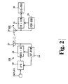
- the signal-transmitting unit 101 has, as shown in FIG. 2, an analog-to-digital converter 22 ("A/D” in FIG. 2), a modulating/transmitting unit 23("MOD TX” in FIG. 2), a radio power-supply unit 24 ("RF-POWER” in FIG. 2), and a transmitting antenna 25.
- the modulating/transmitting unit 23 functions as a radio transmitter.
- the analog-to-digital converter 22 is connected to the AE sensor 21 and used to convert the analog signal output from the AE sensor 21, to a digital signal.
- the modulating/transmitting unit 23 modulates the output signal of the AE sensor 21 converted to a digital signal by the analog-to-digital converter 22 so that the output signal may be transmitted by radio.
- the modulation mode and the radio-transmission mode may be of the types widely used and well known. They need not be limited to particular ones. They can be selected from the various modes available.
- the radio-transmission frequency used should better be so-called microwave band, because it is desired that the transmitting antenna 25 be as small as possible.
- the transmitting antenna 25 need not be limited to a particular type, either. It can be of any type that is widely used and well known so long as it suitable for the frequency for the modulating/transmitting unit 23.
- the radio power-supply unit 24 supplies power that is required in the analog-to-digital converter 22 and the modulating/transmitting unit 23,
- the unit 24 is designed to receive radio waves from the signal-receiving unit 102 (later described) via the transmitting antenna 25, converts the radio waves to power, generates a necessary power-supply voltage from the power and applies the power-supply voltage.
- the analog-to-digital converter 22, the modulating/transmitting unit 23 and the radio power-supply unit 24 should be provided in the form of an IC chip. If they are so provided, they will occupy but a very small space in the grinding machine.
- the signal-receiving unit 102 has a receiving antenna 31, a receiving/demodulating unit 32 ("RX ⁇ DEM” in FIG. 2) and a power-supply unit 33 ("PQW-SUP” in FIG. 2).
- the unit 32 is used as receiver.
- a signal-processing unit 34 (“SIG-PRO” in FIG. 2) is provided.
- This unit 34 which is used as signal processor, processes the signal output from the AE sensor 21 and reproduced in the signal-receiving unit 102, and generates signals that can control the grinding machine.
- the signal-processing unit 34 may be incorporated in the signal-receiving section 102 or provided outside the signal-receiving section 102. Alternatively, the signal-processing unit 34 may be provided in the signal-transmitting unit 101. Further, the signal-processing unit 34 may be the control unit (not shown) that controls the grinding machine.
- the receiving antenna 31 is almost identical to the transmitting antenna 25.
- the receiving/demodulating unit 32 receives and demodulates a radio signal from the receiving antenna 31, which has caught the radio signal transmitted from the signal-transmitting unit 101.
- the power-supply unit 33 supplies power to the receiving/demodulating unit 32. It supplies power by radio to the signal-transmitting unit 101, too, while the signal-receiving unit 102 is receiving no radio signals form the signal-transmitting unit 101.
- the power-supply unit 33 may supply power to the signal-processing unit 34, too, whenever necessary.
- the receiving/demodulating unit 32 and the power-supply unit 33 should better be provided in the form of an IC chip, like as in the signal-transmitting unit 101.
- the AE sensor 21 generates a signal representing the level of ultrasonic waves.
- the analog-to-digital converter 22 converts the signal to a digital signal.
- the digital signal is supplied via the modulating/transmitting unit 23 to the transmitting antenna 25.
- the antenna 25 transmits the digital signal by radio.
- the receiving antenna 31 receives the radio signal transmitted from the transmitting antenna 25.
- the signal received is input to the receiving/demodulating unit 32.
- the unit 32 amplifies and demodulates the signal, generating a digital signal that represents the ultrasonic waves the AE sensor 21 has detected.
- the digital signal produced in the receiving/demodulating unit 32 is input to the signal-processing unit 34.
- the unit 34 processes the digital signal, generating a signal that is necessary to operate, control and so forth the grinding machine.
- the detection signal generated when the grindstone 6 contacts the workpiece 5 is transmitted by radio to the receiving side. Therefore, the detection signal can be transmitted and received without using so much time or labor as in the conventional apparatus wherein the electromagnetic induction between two coils is utilized to transmit a detection signal and should therefore be precisely adjusted in position to be on the same axis.
- the AE sensor 21, analog-to-digital converter 22, modulating/transmitting unit 23 and transmitting antenna 25 constitute a detecting/radio-transmitting means
- the radio power-supply unit 24 and power-supply unit 33 constitute a radio power-supply means
- the receiving antenna 31 and receiving/demodulating unit 32 constitute a receiving means.
- the second configuration provides a detection-signal transmitting apparatus for a grinding machine that has a dressing apparatus. It is suitable for detecting a contact between the grindstone 6 and the dresser 41, both used in the machine.
- the grinding machine related to this configuration is identical in structure to the machine shown in FIG. 1, except that it has a dressing apparatus that will be described below.
- the dressing apparatus has, as major components, a dresser motor 40 and a dresser 41.
- the dresser 41 shaped like a disc can be rotated by the dresser motor 40. Its basic structure is well known to the public.
- the dresser 41 comprises a main body 41a shaped like a disc and holding members 41b and 41d, both shaped like shaped like a disc and holding the main body 41a a between them.
- One holding member 41b for example, is secured to the dresser motor 40 and located remote from the dresser motor 40.
- the other holding member 41c is secured to the dresser motor 40 and located near the dresser motor 40.
- An AE sensor 21 is attached to an appropriate part of the circumferential surface of the holding member 41b.
- a signal-transmitting unit 101 is mounted on the center part of the holding member 41b.
- a signal-receiving unit 102 is mounted on the case 40a of the dresser motor 40, at an appropriate position on the case 40a.
- the signal-transmitting unit 101 and the signal-receiving unit 102 are identical in configuration to those shown in FIG. 2. Therefore, they will not be described in detail.
- the signal detected by the AE sensor 21 is supplied to the analog-to-digital converter 22.
- the converter 22 converts the signal to a digital signal.
- the modulating/transmitting unit 23 sends the digital signal to the transmitting antenna 25, which transmits the signal by radio.
- the radio signal transmitted from the transmitting antenna 25 is input via the receiving antenna 31 to the receiving/demodulating unit 32.
- the receiving/demodulating unit 32 amplifies and demodulates the signal, generating a digital signal that represents the ultrasonic waves the AE sensor 21 has detected.
- the digital signal generated by the unit 32 and representing the ultrasonic waves is input to the signal-processing unit 34.
- the unit 34 processes the digital signal, generating a signal that is necessary to operate, control and so forth the grinding machine.
- the detection signal of the ultrasonic waves generated as the dresser 41 contacts the grindstone 6 is transmitted by radio to the receiving side. Therefore, the detection signal can be transmitted and received without using so much time or labor as in the conventional apparatus wherein the electromagnetic induction between two coils is utilized to transmit a detection signal and should therefore be precisely adjusted in position to be on the same axis.
- the AE sensor 21, analog-to-digital converter 22, modulating/transmitting unit 23 and transmitting antenna 25 constitute a detecting/radio-transmitting means
- the radio power-supply unit 24 and power-supply unit 33 constitute a radio power-supply means
- the receiving antenna 31 and receiving/demodulating unit 32 constitute a receiving means.
- the AE sensor 21, the analog-to-digital converter 22, modulating/transmitting unit 23 and transmitting antenna 25 constitute a detecting/radio-transmitting means
- the radio power-supply unit 24 and power-supply unit 33 constitute a radio power-supply means
- the receiving antenna 31 and receiving/demodulating unit 32 constitute a receiving means. Therefore, an AE-signal transmitting apparatus for use on dressing apparatus is provided.
- radio power-supply unit 24 and the power-supply unit 33 constitute a radio-power supplying device in the dressing apparatus of this configuration.
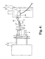
- FIG. 4 A third configuration will be described, with reference to FIG. 4 and FIG. 5.
- the components identical to those shown in FIG. 1 are designated at the same reference numbers and will not be described in detail. Only the different features will be described below.
- the third configuration provides a detection-signal transmitting apparatus that is suitable for transmitting, particularly a detection signal representing the flexure of the grindstone shaft 9 of a grinding machine.
- the grinding machine related to this configuration is basically identical in structure to the machine shown in FIG. 1.
- a flexure-detecting element 51 that detects the flexure of the grindstone shaft 9 is attached at an appropriate position on the grindstone shaft 9 (see FIG. 4 and FIG. 5).
- the flexure-detecting element 51 is preferably a piezoelectric element and strain gauge, for example.
- a signal-transmitting unit 101 is provided at an appropriate position near the flexure-detecting element 51 that is mounted on the periphery of the grindstone shaft 9.
- a signal-receiving unit 102 is mounted at an appropriate position.
- the position of the signal-receiving unit 102 is not limited to this.
- the unit 102 may be provided at, for example, an appropriate position on the sliding table 7.
- the signal-transmitting unit 101 and the signal-receiving unit 102 are identical to those shown in FIG. 2. Therefore, they will not be described in detail.
- the grindstone shat 9 is flexed in accordance with the condition in which the grindstone 6 grinds the workpiece 5.
- the flexure-detecting element 51 detects this flexure, generating an analog signal that corresponds to the flexure detected.
- the signal is input from the element 51 to the analog-to-digital converter 22.
- the converter 22 converts the signal to a digital signal.
- the modulating/transmitting unit 23 sends the digital signal to the transmitting antenna 25, which transmits the signal by radio.
- the radio signal transmitted from the transmitting antenna 25 is input via the receiving antenna 31 to the receiving/demodulating unit 32.
- the unit 32 amplifies and demodulates the signal, generating a digital signal that represents the flexure of the grindstone shat 9.
- the digital signal generated by the unit 32 and representing the flexure is input to the signal-processing unit 34.
- the unit 34 processes the digital signal, generating a signal that can control the grinding machine.
- the flexure-detecting element 51, analog-to-digital converter 22, modulating/transmitting unit 23 and transmitting antenna 25 constitute a detecting/radio-transmitting means
- the radio power-supply unit 24 and power-supply unit 33 constitute a radio power-supply means
- the receiving antenna 31 and receiving/demodulating unit 32 constitute a receiving means. Therefore, a detection-signal transmitting apparatus for use on machine tools is provided.
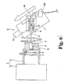
- FIG. 6 A fourth configuration will be described, with reference to FIG. 6.
- the components identical to those shown in FIG. 1 are designated at the same reference numbers and will not be described in detail. Only the different features will be described below.
- the fourth configuration provides a detection-signal transmitting apparatus that is suitable for transmitting, particularly a detection signal representing the temperature of the grindstone shaft 9 of a grinding machine.
- the grinding machine related to this configuration is basically identical in structure to the machine shown in FIG. 1.
- the bearing 11 of the grindstone spindle body 8 generates heat as the grindstone shaft 9 rotates.
- the heat raises the temperature of the grindstone shaft 9, which undergoes thermal expansion.
- the grindstone 6 may be displaced in its thrust direction.
- the displacement of the grindstone 6, in the thrust direction thereof greatly influences the finished precision of the space and the seat. Therefore, the temperature of the grindstone shaft 9 must be detected in some cases, as one parameter for controlling the position of the grindstone 6.
- the configuration shown in FIG. 6 is fit for detecting the temperature of the grindstone shaft 9 in such a case.
- a temperature sensor 61 is adhered to the grindstone shaft 9, more particularly at an appropriate position on the outer circumferential surface of the grindstone shaft 9 that lies in the grindstone spindle body 8.
- a signal-transmitting unit 101 is provided in that end of the grindstone spindle body 8, which is remote from the grindstone 6.
- a signal-receiving unit 102 is mounted on the sliding table 7, at an appropriate position on the table 7.
- the signal-transmitting unit 101 and the signal-receiving unit 102 are identical to those shown in FIG. 2. Therefore, they will not be described in detail
- the operation of this configuration will be explained, with reference to FIG. 2 and FIG. 6. Grinding is started, and the grindstone 6 grinds the workpiece 5. As the bearing 11 rotates, heat is generated, raising the temperature of the grindstone shaft 9. The temperature sensor 61 adhered to the grindstone shaft 9 detects this change in temperature of the grindstone shaft 9 and generates a detection signal. The signal-transmitting unit 101 transmits, by radio, the detection signal in the form of a digital signal, in the same way as in the configurations described above.
- the digital signal is received and demodulated in the signal-receiving unit 102.
- the digital signal is input to the signal-processing unit 34.
- the unit 34 processes the digital signal, generating a signal that is necessary to operate, control and so forth the grinding machine.
- the temperature sensor 61, analog-to-digital converter 22, modulating/transmitting unit 23 and transmitting antenna 25 constitute a detecting/radio-transmitting means
- the radio power-supply unit 24 and power-supply unit 33 constitute a radio power-supply means
- the receiving antenna 31 and receiving/demodulating unit 32 constitute a receiving means. Therefore, a detection-signal transmitting apparatus for use on machine tools is provided.
- the analog-to-digital converter 22, modulating/transmitting unit 23, transmitting antenna 25, receiving antenna 31 and receiving/demodulating unit 32 constitute a transmitting/receiving means.
- the AE sensor 21, the flexure-detecting element 51, or the temperature sensor 61 is used as detecting means.
- a detection-signal transmitting apparatus is provided.
- the analog-to-digital converter 22, modulating/transmitting unit 23, transmitting antenna 25, receiving antenna 31 and receiving/demodulating unit 32 constitute a transmitting/receiving means.
- the radio power-supply unit 24 and power-supply unit 33 constitute a radio power-supply means.
- this invention does not require troublesome adjustment for installation and can easily transmit a detection signal representing changes of an object observed, to any desirable site without performing complex adjustment on the signal.
- this invention can provide an apparatus that is as small as is demanded and can yet transmit a reliable detection signal to any site desired.
- the detection-signal transmitting apparatuses according to the present invention are suitable for detecting the condition in which a workpiece is being ground in various machine tools, such as a dressing apparatus.
Landscapes
- Engineering & Computer Science (AREA)
- Mechanical Engineering (AREA)
- Physics & Mathematics (AREA)
- Acoustics & Sound (AREA)
- General Physics & Mathematics (AREA)
- Arrangements For Transmission Of Measured Signals (AREA)
- Constituent Portions Of Griding Lathes, Driving, Sensing And Control (AREA)
- Machine Tool Sensing Apparatuses (AREA)
- Grinding-Machine Dressing And Accessory Apparatuses (AREA)
- Investigating Or Analyzing Materials By The Use Of Ultrasonic Waves (AREA)
Abstract
Description
- The present invention relates to a detection-signal transmitting apparatus that detects changes of an object observed and transmits detected signals representing the changes. More particularly, the invention relates to an apparatus designed to transmit detection signals easily to a site that is remote from the object,
- In some cases, it is required that changes in various objects observed be detected in order to control various electronic devices and that the signals representing the changes be transmitted to a site desired.
- More specifically, in a grinding machine and the like, for example, the condition in which a grindstone contacts a work piece should be detected in order to control the position of the grindstone. As well known, when the grindstone contacts the workpiece, ultrasonic waves are generated. If the ultrasonic waves generated at the moment the grindstone contacts the workpiece are detected, the condition in which the grindstone contacts the workpiece can be recognized from the level of the signal of the ultrasonic waves. Hence, various apparatuses for detecting ultrasonic waves and transmitting the signal have been proposed.
- For example,
Patent Document 1 discloses a grinding machine, which is hence known to the public. This machine uses a piezoelectric element, which is attached to a grindstone to detect ultrasonic waves that are generated when the grindstone contacts a workpiece. A first coil is connected in series to the piezoelectric element. A second coil is arranged on the central axis of the first coil and thus opposed thereto. The electromagnetic coupling of the first and second coils can induce, at the second coil, the ultrasonic-wave signal detected by the piezoelectric element. - In the conventional grinding machine described above, however, the first and second coils must be precisely adjusted in position to be arranged on the same axis axis so that the magnetic coupling between them may be effective. Further, sites where the machine can be installed are limited because of its configuration. That is, the machine has small freedom of use. Moreover, the first and second coils need to have so many turns and so large a size that any signal the second coil generates is at a level high enough to be processed well. Therefore, the conventional grinding machine can hardly be as small as is generally demanded.
Patent Document 1:European Pat. Appln. Publication No. 446849 - The present invention has been made in view of the foregoing. An object of this invention is to provide a detection-signal transmitting apparatus, a detection-signal transmitting apparatus for machine tools, an AE-signal transmitting apparatus for dressing apparatus, and a dressing apparatus, each of which can easily transmit to any desired site a detection signal representing changes of an object observed, has large freedom of installation and requires only minimum adjustment before use.
- Another object of this invention is to provide a detection-signal transmitting apparatus, a detection-signal transmitting apparatus for machine tools, an AE-signal transmitting apparatus for dressing apparatus, and a dressing apparatus, each of which can meet the demand for miniaturization and can generate stable detection signals of a sufficiently high level.
- According to a first embodiment of this invention, a detection-signal transmitting apparatus is provided. The apparatus comprises: a detecting means for detecting changes in condition of an object; and a transmitting/receiving means for transmitting and receiving, by radio, a signal output from the detecting means.
- According to a second embodiment of this invention, a detection-signal transmitting apparatus for use on a machine tool. This apparatus is designed to detect a change in condition of an object being machined by a machine tool and to transmit a signal for controlling the machine tool. The apparatus comprises: a detecting/radio-transmitting means for detecting changes in condition of an object, converting a detection signal to a digital signal and transmitting the digital signal by radio; a radio power-supplying means for supplying external power, by radio, to the detecting/radio-transmitting means; and a receiving means for receiving and demodulating the signal transmitted from the detecting/radio-transmitting means.
- According to a third embodiment of this invention, an AE-signal transmitting apparatus for use on a dressing apparatus is provided. The transmitting apparatus comprises: a detecting/radio-transmitting means for detecting ultrasonic waves generated when a grindstone contacts a dresser, converting a detection signal to a digital signal and transmitting the digital signal by radio; a radio power-supplying means for supplying external power, by radio, to the detecting/radio-transmitting means; and a receiving means for receiving and demodulating the signal transmitted from the detecting/radio-transmitting means.
- According to a fourth embodiment of this invention, a dressing apparatus for performing dressing on a grindstone is provided, The dressing apparatus comprises: an ultrasonic-wave detector that detects ultrasonic waves generated when a grindstone contacts a dresser; a digital converter that converts an output signal of the ultrasonic-wave detector to a digital signal; a radio transmitter that transmits, by radio, an output signal of the digital converter; a radio power-supply unit that supplies external power, by radio, to the digital converter and the radio transmitter; a receiver that receives and demodulates a signal transmitted from the radio transmitter; and a signal processor that processes and converts a detection signal generated by ultrasonic-wave detector and demodulated by the receiver, to a predetermined signal for controlling the dressing.
-
- FIG. 1
- is a diagram showing the first configuration of a detection-signal transmitting apparatus according to an embodiment of this invention;
- FIG. 2
- is a diagram depicting the configurations of a signal-transmitting unit and a signal-receiving unit, both used in the detection-signal transmitting apparatus according to the embodiment of the invention;
- FIG. 3
- is a diagram showing the second configuration of the detectionsignal transmitting apparatus according to the embodiment of this invention;
- FIG. 4
- is a diagram showing the third configuration of the detection-signal transmitting apparatus according to the embodiment of this invention;
- FIG. 5
- is a sectional view of the configuration shown in FIG. 4, taken along line A-A; and
- FIG. 6
- is a diagram showing the fourth configuration of the detectionsignal transmitting apparatus according to the embodiment of this invention.
- Embodiments of the present invention will be described, with reference to FIG. 1 to FIG. 6.
- The members, arrangements and the like that are described hereinafter are not intended to limit this invention and various modifications can be made without departing from the scope of this invention.
- First, the first configuration of a detection-signal transmitting apparatus according to an embodiment of this invention will be described, with reference to FIG. 1 and FIG. 2.
- The first configuration is a detection-signal transmitting apparatus for use on grinding machines, This configuration is fit for, particularly, detection of a contact between a grindstone 6 and a workpiece 5.
- The configuration of the apparatus will be described in detail. The grinding machine is of a configuration that is well known to the public. It has a workpiece-
holding unit 1 and a grindstone-holding unit 2. Theunit 1 holds a workpiece 5 as will be explained later. Theunit 2 holds a grindstone 6 and moves the same to and from the workpiece 5. - The workpiece-
holding unit 1 comprises amain section 3 and a rotating-side chuck 4. Themain section 3 is fixed to a base that is secured on an installation floor (not shown). The rotating-side chuck 4 can be driven by a motor (not shown) that is incorporated in themain section 3. - At least that part of the rotating-side chuck 4, which protrudes from the
main section 3, is shaped like a hollow cylinder. The workpiece 5 is removably attached to the distal end of that part of the rotating-side chuck 4. - On the other hand, the grindstone-
holding unit 2 has asliding base 7, to which the grindstone 6 is attached as will be described below. - That is, a
grindstone spindle unit 8 to which the grindstone 6 is attached is provided on thesliding base 7 and can be rotated by a motor (not shown). The grindstone 6 is removably secured to one end of agrindstone shaft 9. The other end of thegrindstone shaft 9 is inserted in thegrindstone spindle unit 8. - The sliding
base 7 can move on a field table 14 (see FIG. 3), approaching the workpiece 5, as a feed-inmotor 10 is driven. The field table 14 is moved as a motor (not shown) is driven by means of NC control. Further, the slidingbase 7 can rotate on the field table 14, and thegrindstone spindle unit 8 can rotate on the sliding table 7 (see FIG. 6). - In the grinding machine thus configured, as a detection means, an AE sensor (ultrasonic-wave sensor) 21 is provided at an appropriate position on the circumferential surface of the rotating-side chuck 4. A signal-transmitting
unit 101 is provided in the rotating-side chuck 4. - Further, a signal-receiving
unit 102 is provided at an appropriate position on the workpiece-holdingunit 1, for example, at an appropriate position on themain section 3. - To be more specific, the signal-transmitting
unit 101 has, as shown in FIG. 2, an analog-to-digital converter 22 ("A/D" in FIG. 2), a modulating/transmitting unit 23("MOD TX" in FIG. 2), a radio power-supply unit 24 ("RF-POWER" in FIG. 2), and a transmittingantenna 25. The modulating/transmitting unit 23 functions as a radio transmitter. - The analog-to-
digital converter 22 is connected to theAE sensor 21 and used to convert the analog signal output from theAE sensor 21, to a digital signal. - The modulating/transmitting unit 23 modulates the output signal of the
AE sensor 21 converted to a digital signal by the analog-to-digital converter 22 so that the output signal may be transmitted by radio. The modulation mode and the radio-transmission mode may be of the types widely used and well known. They need not be limited to particular ones. They can be selected from the various modes available. The radio-transmission frequency used should better be so-called microwave band, because it is desired that the transmittingantenna 25 be as small as possible. - The transmitting
antenna 25 need not be limited to a particular type, either. It can be of any type that is widely used and well known so long as it suitable for the frequency for the modulating/transmitting unit 23. - The radio power-
supply unit 24 supplies power that is required in the analog-to-digital converter 22 and the modulating/transmitting unit 23, Theunit 24 is designed to receive radio waves from the signal-receiving unit 102 (later described) via the transmittingantenna 25, converts the radio waves to power, generates a necessary power-supply voltage from the power and applies the power-supply voltage. - Preferably, the analog-to-
digital converter 22, the modulating/transmitting unit 23 and the radio power-supply unit 24 should be provided in the form of an IC chip. If they are so provided, they will occupy but a very small space in the grinding machine. - On the other hand, the signal-receiving
unit 102 has a receivingantenna 31, a receiving/demodulating unit 32 ("RX·DEM" in FIG. 2) and a power-supply unit 33 ("PQW-SUP" in FIG. 2). Theunit 32 is used as receiver. A signal-processing unit 34 ("SIG-PRO" in FIG. 2) is provided. Thisunit 34, which is used as signal processor, processes the signal output from theAE sensor 21 and reproduced in the signal-receivingunit 102, and generates signals that can control the grinding machine. The signal-processingunit 34 may be incorporated in the signal-receivingsection 102 or provided outside the signal-receivingsection 102. Alternatively, the signal-processingunit 34 may be provided in the signal-transmittingunit 101. Further, the signal-processingunit 34 may be the control unit (not shown) that controls the grinding machine. - The receiving
antenna 31 is almost identical to the transmittingantenna 25. The receiving/demodulating unit 32 receives and demodulates a radio signal from the receivingantenna 31, which has caught the radio signal transmitted from the signal-transmittingunit 101. The power-supply unit 33 supplies power to the receiving/demodulating unit 32. It supplies power by radio to the signal-transmittingunit 101, too, while the signal-receivingunit 102 is receiving no radio signals form the signal-transmittingunit 101. The power-supply unit 33 may supply power to the signal-processingunit 34, too, whenever necessary. - Note that the receiving/
demodulating unit 32 and the power-supply unit 33 should better be provided in the form of an IC chip, like as in the signal-transmittingunit 101. - The operation of the configuration described above will be explained with reference to FIGS. 1 and 2. When the grindstone 6 contacts the workpiece 5, grinding the workpiece 5, ultrasonic waves are generated. The ultrasonic waves propagate through the workpiece 5 and the rotating-side chuck 4 and are detected by the
AE sensor 21. The level of the ultrasonic waves varies in accordance with the depth to which the workpiece 5 is ground by the grindstone 6. Hence, the ultrasonic waves detected can be utilized to control the position of the grindstone 6. - The
AE sensor 21 generates a signal representing the level of ultrasonic waves. The analog-to-digital converter 22 converts the signal to a digital signal. The digital signal is supplied via the modulating/transmitting unit 23 to the transmittingantenna 25. Theantenna 25 transmits the digital signal by radio. - The receiving
antenna 31 receives the radio signal transmitted from the transmittingantenna 25. The signal received is input to the receiving/demodulating unit 32. Theunit 32 amplifies and demodulates the signal, generating a digital signal that represents the ultrasonic waves theAE sensor 21 has detected. The digital signal produced in the receiving/demodulating unit 32 is input to the signal-processingunit 34. Theunit 34 processes the digital signal, generating a signal that is necessary to operate, control and so forth the grinding machine. - In the configuration described above, the detection signal generated when the grindstone 6 contacts the workpiece 5 is transmitted by radio to the receiving side. Therefore, the detection signal can be transmitted and received without using so much time or labor as in the conventional apparatus wherein the electromagnetic induction between two coils is utilized to transmit a detection signal and should therefore be precisely adjusted in position to be on the same axis.
- In the above-described configuration, the
AE sensor 21, analog-to-digital converter 22, modulating/transmitting unit 23 and transmittingantenna 25 constitute a detecting/radio-transmitting means, the radio power-supply unit 24 and power-supply unit 33 constitute a radio power-supply means, and the receivingantenna 31 and receiving/demodulating unit 32 constitute a receiving means. These means constitute a detection-signal transmitting apparatus for machine tools. - Next, a second configuration will be described, with reference to FIG. 3. The components identical to those shown in FIG. 1 are designated at the same reference numbers and will not be described in detail. Only the different features will be described below.
- The second configuration provides a detection-signal transmitting apparatus for a grinding machine that has a dressing apparatus. It is suitable for detecting a contact between the grindstone 6 and the
dresser 41, both used in the machine. - The grinding machine related to this configuration is identical in structure to the machine shown in FIG. 1, except that it has a dressing apparatus that will be described below.
- The dressing apparatus has, as major components, a
dresser motor 40 and adresser 41. Thedresser 41 shaped like a disc can be rotated by thedresser motor 40. Its basic structure is well known to the public. Thedresser 41 comprises amain body 41a shaped like a disc and holdingmembers 41b and 41d, both shaped like shaped like a disc and holding themain body 41a a between them. One holdingmember 41b, for example, is secured to thedresser motor 40 and located remote from thedresser motor 40. The other holdingmember 41c is secured to thedresser motor 40 and located near thedresser motor 40. AnAE sensor 21 is attached to an appropriate part of the circumferential surface of the holdingmember 41b. A signal-transmittingunit 101 is mounted on the center part of the holdingmember 41b. A signal-receivingunit 102 is mounted on thecase 40a of thedresser motor 40, at an appropriate position on thecase 40a. - The signal-transmitting
unit 101 and the signal-receivingunit 102 are identical in configuration to those shown in FIG. 2. Therefore, they will not be described in detail. - The operation of this configuration will be explained, with reference to FIG. 2 and FIG. 3. When the
dresser 41 contacts the grindstone 6, starting dressing, ultrasonic waves are generated. The ultrasonic waves propagate through thedresser 41. TheAE sensor 21 detects the waves. The level of the waves varies with the amount of dressing thedresser 41 performs on the grindstone 6, Hence, the ultrasonic waves detected can be used to control the position of thedresser 41. - The signal detected by the
AE sensor 21 is supplied to the analog-to-digital converter 22. Theconverter 22 converts the signal to a digital signal. The modulating/transmitting unit 23 sends the digital signal to the transmittingantenna 25, which transmits the signal by radio. - The radio signal transmitted from the transmitting
antenna 25 is input via the receivingantenna 31 to the receiving/demodulating unit 32. The receiving/demodulating unit 32 amplifies and demodulates the signal, generating a digital signal that represents the ultrasonic waves theAE sensor 21 has detected. The digital signal generated by theunit 32 and representing the ultrasonic waves is input to the signal-processingunit 34. Theunit 34 processes the digital signal, generating a signal that is necessary to operate, control and so forth the grinding machine. - Thus, the detection signal of the ultrasonic waves generated as the
dresser 41 contacts the grindstone 6 is transmitted by radio to the receiving side. Therefore, the detection signal can be transmitted and received without using so much time or labor as in the conventional apparatus wherein the electromagnetic induction between two coils is utilized to transmit a detection signal and should therefore be precisely adjusted in position to be on the same axis. - In this configuration described above, the
AE sensor 21, analog-to-digital converter 22, modulating/transmitting unit 23 and transmittingantenna 25 constitute a detecting/radio-transmitting means, the radio power-supply unit 24 and power-supply unit 33 constitute a radio power-supply means, and the receivingantenna 31 and receiving/demodulating unit 32 constitute a receiving means. These means constitute a detection-signal transmitting apparatus for machine tools. - As indicated above, the
AE sensor 21, the analog-to-digital converter 22, modulating/transmitting unit 23 and transmittingantenna 25 constitute a detecting/radio-transmitting means, the radio power-supply unit 24 and power-supply unit 33 constitute a radio power-supply means, and the receivingantenna 31 and receiving/demodulating unit 32 constitute a receiving means. Therefore, an AE-signal transmitting apparatus for use on dressing apparatus is provided. - Further, the radio power-
supply unit 24 and the power-supply unit 33 constitute a radio-power supplying device in the dressing apparatus of this configuration. - A third configuration will be described, with reference to FIG. 4 and FIG. 5. The components identical to those shown in FIG. 1 are designated at the same reference numbers and will not be described in detail. Only the different features will be described below.
- The third configuration provides a detection-signal transmitting apparatus that is suitable for transmitting, particularly a detection signal representing the flexure of the
grindstone shaft 9 of a grinding machine. The grinding machine related to this configuration is basically identical in structure to the machine shown in FIG. 1. In this grinding machine, a flexure-detectingelement 51 that detects the flexure of thegrindstone shaft 9 is attached at an appropriate position on the grindstone shaft 9 (see FIG. 4 and FIG. 5). Here, the flexure-detectingelement 51 is preferably a piezoelectric element and strain gauge, for example. - A signal-transmitting
unit 101 is provided at an appropriate position near the flexure-detectingelement 51 that is mounted on the periphery of thegrindstone shaft 9. On thegrindstone spindle unit 8, a signal-receivingunit 102 is mounted at an appropriate position. The position of the signal-receivingunit 102 is not limited to this. Theunit 102 may be provided at, for example, an appropriate position on the sliding table 7. The signal-transmittingunit 101 and the signal-receivingunit 102 are identical to those shown in FIG. 2. Therefore, they will not be described in detail. - The operation of this configuration will be explained, with reference to FIG. 2 and FIG. 4. After the grinding is started, the grindstone shat 9 is flexed in accordance with the condition in which the grindstone 6 grinds the workpiece 5. The flexure-detecting
element 51 detects this flexure, generating an analog signal that corresponds to the flexure detected. The signal is input from theelement 51 to the analog-to-digital converter 22. Theconverter 22 converts the signal to a digital signal. The modulating/transmitting unit 23 sends the digital signal to the transmittingantenna 25, which transmits the signal by radio. - The radio signal transmitted from the transmitting
antenna 25 is input via the receivingantenna 31 to the receiving/demodulating unit 32. Theunit 32 amplifies and demodulates the signal, generating a digital signal that represents the flexure of the grindstone shat 9. The digital signal generated by theunit 32 and representing the flexure is input to the signal-processingunit 34. Theunit 34 processes the digital signal, generating a signal that can control the grinding machine. - In the configuration described above, the flexure-detecting
element 51, analog-to-digital converter 22, modulating/transmitting unit 23 and transmittingantenna 25 constitute a detecting/radio-transmitting means, the radio power-supply unit 24 and power-supply unit 33 constitute a radio power-supply means, and the receivingantenna 31 and receiving/demodulating unit 32 constitute a receiving means. Therefore, a detection-signal transmitting apparatus for use on machine tools is provided. - A fourth configuration will be described, with reference to FIG. 6. The components identical to those shown in FIG. 1 are designated at the same reference numbers and will not be described in detail. Only the different features will be described below.
- The fourth configuration provides a detection-signal transmitting apparatus that is suitable for transmitting, particularly a detection signal representing the temperature of the
grindstone shaft 9 of a grinding machine. The grinding machine related to this configuration is basically identical in structure to the machine shown in FIG. 1. - In this grinding machine, the bearing 11 of the
grindstone spindle body 8 generates heat as thegrindstone shaft 9 rotates. The heat raises the temperature of thegrindstone shaft 9, which undergoes thermal expansion. Thus, the grindstone 6 may be displaced in its thrust direction. In processes of forming aspace 12 in the workpiece 5 and forming aconical seat 13, in particular, the displacement of the grindstone 6, in the thrust direction thereof, greatly influences the finished precision of the space and the seat. Therefore, the temperature of thegrindstone shaft 9 must be detected in some cases, as one parameter for controlling the position of the grindstone 6. - The configuration shown in FIG. 6 is fit for detecting the temperature of the
grindstone shaft 9 in such a case. Atemperature sensor 61 is adhered to thegrindstone shaft 9, more particularly at an appropriate position on the outer circumferential surface of thegrindstone shaft 9 that lies in thegrindstone spindle body 8. A signal-transmittingunit 101 is provided in that end of thegrindstone spindle body 8, which is remote from the grindstone 6. - A signal-receiving
unit 102 is mounted on the sliding table 7, at an appropriate position on the table 7. The signal-transmittingunit 101 and the signal-receivingunit 102 are identical to those shown in FIG. 2. Therefore, they will not be described in detail - The operation of this configuration will be explained, with reference to FIG. 2 and FIG. 6. Grinding is started, and the grindstone 6 grinds the workpiece 5. As the bearing 11 rotates, heat is generated, raising the temperature of the
grindstone shaft 9. Thetemperature sensor 61 adhered to thegrindstone shaft 9 detects this change in temperature of thegrindstone shaft 9 and generates a detection signal. The signal-transmittingunit 101 transmits, by radio, the detection signal in the form of a digital signal, in the same way as in the configurations described above. - The digital signal is received and demodulated in the signal-receiving
unit 102. The digital signal is input to the signal-processingunit 34. Theunit 34 processes the digital signal, generating a signal that is necessary to operate, control and so forth the grinding machine. - In the configuration described above, the
temperature sensor 61, analog-to-digital converter 22, modulating/transmitting unit 23 and transmittingantenna 25 constitute a detecting/radio-transmitting means, the radio power-supply unit 24 and power-supply unit 33 constitute a radio power-supply means, and the receivingantenna 31 and receiving/demodulating unit 32 constitute a receiving means. Therefore, a detection-signal transmitting apparatus for use on machine tools is provided. - In any configuration described above, the analog-to-
digital converter 22, modulating/transmitting unit 23, transmittingantenna 25, receivingantenna 31 and receiving/demodulating unit 32 constitute a transmitting/receiving means. TheAE sensor 21, the flexure-detectingelement 51, or thetemperature sensor 61 is used as detecting means. Thus, a detection-signal transmitting apparatus is provided. - The analog-to-
digital converter 22, modulating/transmitting unit 23, transmittingantenna 25, receivingantenna 31 and receiving/demodulating unit 32 constitute a transmitting/receiving means. The radio power-supply unit 24 and power-supply unit 33 constitute a radio power-supply means. Thus, a detection-signal transmitting apparatus is provided. - The configurations described above are grinding machines. Nonetheless, the present invention is not limited to these machines. The invention can be applied to, for example, cutting machines in a similar manner.
- Unlike the conventional techniques, this invention does not require troublesome adjustment for installation and can easily transmit a detection signal representing changes of an object observed, to any desirable site without performing complex adjustment on the signal.
- In addition, unlike the conventional techniques, this invention can provide an apparatus that is as small as is demanded and can yet transmit a reliable detection signal to any site desired.
- The detection-signal transmitting apparatuses according to the present invention are suitable for detecting the condition in which a workpiece is being ground in various machine tools, such as a dressing apparatus.
Claims (5)
- , A detection-signal transmitting apparatus characterized by comprising: detecting means for detecting changes in condition of an object; and transmitting/receiving means for transmitting and receiving, by radio, a signal output from the detecting means.
- A detection-signal transmitting apparatus characterized by comprising: detecting means for detecting changes in condition of an object; transmitting/receiving means for transmitting and receiving, by radio, a signal output from the detecting means; and radio power-supplying means for supplying power, by radio, to the transmitting/receiving means.
- A detection-signal transmitting apparatus for use on a machine tool, designed to detect a change in condition of an object being machined by a machine tool and to transmit a signal for controlling the machine tool, said apparatus characterized by comprising:detecting/radio-transmitting means for detecting changes in condition of an object, converting a detection signal to a digital signal and transmitting the digital signal by radio;radio power-supplying means for supplying external power, by radio, to the detecting/radio-transmitting means;and receiving means for receiving and demodulating the signal transmitted from the detecting/radio-transmitting means.
- An AE-signal transmitting apparatus for use on a dressing apparatus, characterized by comprising:detecting/radio-transmitting means for detecting ultrasonic waves generated when a grindstone contacts a dresser, converting a detection signal to a digital signal and transmitting the digital signal by radio;radio power-supplying means for supplying external power, by radio, to the detecting/radio-transmitting means;and receiving means for receiving and demodulating the signal transmitted from the detecting/radio-transmitting means.
- A dressing apparatus for performing dressing on a grindstone, characterized by comprising:an ultrasonic-wave detector that detects ultrasonic waves generated when a grindstone contacts a dresser;a digital converter that converts an output signal of the ultrasonic-wave detector to a digital signal;a radio transmitter that transmits, by radio, an output signal of the digital converter;radio power-supply unit that supplies external power, by radio, to the digital converter and the radio transmitter;a receiver that receives and demodulates a signal transmitted from the radio transmitter;and a signal processor that processes and converts a detection signal generated by ultrasonic-wave detector and demodulated by the receiver, to a predetermined signal for controlling the dressing.
Applications Claiming Priority (2)
| Application Number | Priority Date | Filing Date | Title |
|---|---|---|---|
| JP2004040438A JP2005230934A (en) | 2004-02-17 | 2004-02-17 | Detection signal transmission device |
| PCT/JP2005/002215 WO2005077598A1 (en) | 2004-02-17 | 2005-02-15 | Detection signal transmitting apparatus |
Publications (3)
| Publication Number | Publication Date |
|---|---|
| EP1719579A1 true EP1719579A1 (en) | 2006-11-08 |
| EP1719579A4 EP1719579A4 (en) | 2007-05-02 |
| EP1719579B1 EP1719579B1 (en) | 2008-10-29 |
Family
ID=34857888
Family Applications (1)
| Application Number | Title | Priority Date | Filing Date |
|---|---|---|---|
| EP05719117A Ceased EP1719579B1 (en) | 2004-02-17 | 2005-02-15 | Detection signal transmitting apparatus |
Country Status (7)
| Country | Link |
|---|---|
| US (1) | US7769483B2 (en) |
| EP (1) | EP1719579B1 (en) |
| JP (1) | JP2005230934A (en) |
| KR (1) | KR100809217B1 (en) |
| CN (1) | CN1917984A (en) |
| DE (1) | DE602005010667D1 (en) |
| WO (1) | WO2005077598A1 (en) |
Cited By (4)
| Publication number | Priority date | Publication date | Assignee | Title |
|---|---|---|---|---|
| FR2922130A1 (en) * | 2007-10-16 | 2009-04-17 | Ct Tech De L Ind Du Decolletag | Tool support i.e. plate carrier, for tool carrier in e.g. sugar-beet topper, has transmission unit transmitting signals measured from sensor and carried by support, where transmitting unit transmits and receives signals with radio station |
| EP2050535A1 (en) * | 2007-10-16 | 2009-04-22 | Centre Technique de l'Industrie du Decolletage | Instrumented tool support and associated tool-holder |
| EP2627475A1 (en) * | 2010-10-14 | 2013-08-21 | Handtmann A-Punkt Automation GmbH | Machine tool comprising an ultrasonic sensor |
| EP3970913A1 (en) * | 2020-09-16 | 2022-03-23 | Fraunhofer-Gesellschaft zur Förderung der angewandten Forschung e.V. | Method for the machining of structures on workpiece surfaces and machining tool |
Families Citing this family (10)
| Publication number | Priority date | Publication date | Assignee | Title |
|---|---|---|---|---|
| EP1747846A1 (en) * | 2005-07-25 | 2007-01-31 | Rollomatic S.A. | Method and machine for the measurement of a cutting edge to be grinded |
| JP4820468B2 (en) * | 2005-08-04 | 2011-11-24 | ボッシュ株式会社 | Detection signal transmission device |
| JP5857660B2 (en) * | 2011-06-27 | 2016-02-10 | 株式会社ジェイテクト | Grinding machine truing device |
| CN102621226A (en) * | 2012-04-16 | 2012-08-01 | 上海理工大学 | Device for measuring grinding vibration performance of CBN (cubic boron nitride) grinding wheel matrix |
| CN103786093B (en) * | 2014-03-05 | 2016-08-24 | 威海华东数控股份有限公司 | What a kind of grinding status monitored in real time graphically detects display packing |
| JP2017225259A (en) * | 2016-06-16 | 2017-12-21 | 東芝三菱電機産業システム株式会社 | Rotary machine |
| DE102017123676B4 (en) * | 2017-10-11 | 2025-06-18 | Balluff Gmbh | Sensor device, sensor system and method for operating a sensor device |
| US20230050576A1 (en) * | 2020-01-29 | 2023-02-16 | Noritake Co., Limited | Ae-signal detecting device for abrasive wheel |
| WO2025022525A1 (en) * | 2023-07-24 | 2025-01-30 | 住友電気工業株式会社 | Cutting system and power feeding device |
| JP7663154B1 (en) * | 2023-09-08 | 2025-04-16 | 住友電気工業株式会社 | Cutting systems and cutting tools |
Family Cites Families (13)
| Publication number | Priority date | Publication date | Assignee | Title |
|---|---|---|---|---|
| JPS5439276A (en) * | 1977-09-02 | 1979-03-26 | Mitsubishi Electric Corp | Device for detecting extraordinariness of machine tool or the like |
| JPS5840246A (en) | 1981-08-29 | 1983-03-09 | Sumitomo Electric Ind Ltd | Method for detecting cutter tip damage |
| DE4007838A1 (en) | 1990-03-12 | 1991-09-19 | Dittel Walter Gmbh | DEVICE FOR TOUCH DETECTION |
| JP2810489B2 (en) * | 1990-05-30 | 1998-10-15 | 株式会社ノリタケカンパニーリミテド | Grinding wheel |
| JPH04240049A (en) * | 1991-01-23 | 1992-08-27 | Mitsui Seiki Kogyo Co Ltd | Wireless AE pickup device |
| JP4113986B2 (en) * | 1998-08-12 | 2008-07-09 | エヌティーエンジニアリング株式会社 | Operating state detection device for work machines |
| JP2000263377A (en) * | 1999-03-17 | 2000-09-26 | Ntn Corp | Metal mold machining device |
| US6508614B1 (en) * | 1999-03-17 | 2003-01-21 | Ntn Corporation | Spindle device and machine tool utilizing the same |
| TW490357B (en) | 1999-05-27 | 2002-06-11 | Sanyo Electric Co | Method and device for detecting abnormities of the cutting tool of a cutting machine |
| JP2001116867A (en) * | 1999-10-19 | 2001-04-27 | Hitachi Ltd | XY stage |
| JP2002059342A (en) * | 2000-08-23 | 2002-02-26 | Seiko Epson Corp | Cutting tool wear detection method and wear detection device |
| US7034711B2 (en) * | 2001-08-07 | 2006-04-25 | Nsk Ltd. | Wireless sensor, rolling bearing with sensor, management apparatus and monitoring system |
| JP4240049B2 (en) | 2006-04-11 | 2009-03-18 | トヨタ自動車株式会社 | Powertrain control device |
-
2004
- 2004-02-17 JP JP2004040438A patent/JP2005230934A/en active Pending
-
2005
- 2005-02-15 EP EP05719117A patent/EP1719579B1/en not_active Ceased
- 2005-02-15 WO PCT/JP2005/002215 patent/WO2005077598A1/en not_active Ceased
- 2005-02-15 CN CNA2005800050495A patent/CN1917984A/en active Pending
- 2005-02-15 KR KR1020067016452A patent/KR100809217B1/en not_active Expired - Fee Related
- 2005-02-15 DE DE602005010667T patent/DE602005010667D1/en not_active Expired - Lifetime
-
2006
- 2006-08-16 US US11/504,708 patent/US7769483B2/en not_active Expired - Fee Related
Non-Patent Citations (2)
| Title |
|---|
| No further relevant documents disclosed * |
| See also references of WO2005077598A1 * |
Cited By (4)
| Publication number | Priority date | Publication date | Assignee | Title |
|---|---|---|---|---|
| FR2922130A1 (en) * | 2007-10-16 | 2009-04-17 | Ct Tech De L Ind Du Decolletag | Tool support i.e. plate carrier, for tool carrier in e.g. sugar-beet topper, has transmission unit transmitting signals measured from sensor and carried by support, where transmitting unit transmits and receives signals with radio station |
| EP2050535A1 (en) * | 2007-10-16 | 2009-04-22 | Centre Technique de l'Industrie du Decolletage | Instrumented tool support and associated tool-holder |
| EP2627475A1 (en) * | 2010-10-14 | 2013-08-21 | Handtmann A-Punkt Automation GmbH | Machine tool comprising an ultrasonic sensor |
| EP3970913A1 (en) * | 2020-09-16 | 2022-03-23 | Fraunhofer-Gesellschaft zur Förderung der angewandten Forschung e.V. | Method for the machining of structures on workpiece surfaces and machining tool |
Also Published As
| Publication number | Publication date |
|---|---|
| CN1917984A (en) | 2007-02-21 |
| DE602005010667D1 (en) | 2008-12-11 |
| US20070005177A1 (en) | 2007-01-04 |
| WO2005077598A1 (en) | 2005-08-25 |
| KR20060118588A (en) | 2006-11-23 |
| EP1719579B1 (en) | 2008-10-29 |
| US7769483B2 (en) | 2010-08-03 |
| EP1719579A4 (en) | 2007-05-02 |
| KR100809217B1 (en) | 2008-03-03 |
| JP2005230934A (en) | 2005-09-02 |
Similar Documents
| Publication | Publication Date | Title |
|---|---|---|
| EP1719579A1 (en) | Detection signal transmitting apparatus | |
| US7289873B2 (en) | Sensor system for a cutting machine tool | |
| EP0690979B1 (en) | Apparatus for the dynamic balancing of a rotating body | |
| KR20090024733A (en) | Abrasive article, CPM monitoring system and method | |
| JP2018526231A (en) | Method and device for measuring the resonant frequency of a tool set in an ultrasonic vibration state for machining | |
| JP7038378B2 (en) | Electric tool | |
| US10639761B2 (en) | Grinding wheel and grinding apparatus | |
| EP3134980B1 (en) | Device and method for transceiving alternating optical signals | |
| JP6918230B2 (en) | Manufacturing method of machine tools and scroll compressors | |
| CN115023317A (en) | AE signal detection device of grinding wheel | |
| US10828740B2 (en) | Method of determining pull-out of a cutting tool and a rotatable tool holder for a cutting tool | |
| EP1112810A1 (en) | Machine tool and method of communication | |
| WO2003073051A1 (en) | Acoustic sensor for monitoring machining processes in machining tolls | |
| WO1999046074A1 (en) | Tool positioning structure and working machine | |
| CN101238499B (en) | Detection signal transmission device | |
| JP4113986B2 (en) | Operating state detection device for work machines | |
| US20050193819A1 (en) | Precision sensor assembly for rotating members in a machine tool | |
| JP2022145290A (en) | Ae signal detector for grind stone | |
| CN117320842B (en) | Power tools with wireless signal transmission function | |
| CN120019593A (en) | communication device |
Legal Events
| Date | Code | Title | Description |
|---|---|---|---|
| PUAI | Public reference made under article 153(3) epc to a published international application that has entered the european phase |
Free format text: ORIGINAL CODE: 0009012 |
|
| 17P | Request for examination filed |
Effective date: 20060905 |
|
| AK | Designated contracting states |
Kind code of ref document: A1 Designated state(s): DE FR |
|
| A4 | Supplementary search report drawn up and despatched |
Effective date: 20070404 |
|
| DAX | Request for extension of the european patent (deleted) | ||
| RBV | Designated contracting states (corrected) |
Designated state(s): DE FR |
|
| 17Q | First examination report despatched |
Effective date: 20070529 |
|
| RIC1 | Information provided on ipc code assigned before grant |
Ipc: B23Q 17/22 20060101ALI20071212BHEP Ipc: B23Q 17/09 20060101AFI20071212BHEP Ipc: B24B 49/18 20060101ALI20071212BHEP Ipc: B24B 53/00 20060101ALI20071212BHEP |
|
| GRAP | Despatch of communication of intention to grant a patent |
Free format text: ORIGINAL CODE: EPIDOSNIGR1 |
|
| RIN1 | Information on inventor provided before grant (corrected) |
Inventor name: YUI, TAKAYUKI,C/O BOSCH AUTOMOTIVE SYSTEMS CORP. Inventor name: UENO, HARUHIKO,C/O BOSCH AUTOMOTIVE SYSTEMS CORP. Inventor name: HURUKAWA, HIDEO,C/O BOSCH AUTOMOTIVE SYSTEMS CORP. Inventor name: KUBOTA, OSAMU,C/O BOSCH AUTOMOTIVE SYSTEMS CORP. |
|
| GRAS | Grant fee paid |
Free format text: ORIGINAL CODE: EPIDOSNIGR3 |
|
| GRAA | (expected) grant |
Free format text: ORIGINAL CODE: 0009210 |
|
| AK | Designated contracting states |
Kind code of ref document: B1 Designated state(s): DE FR |
|
| REF | Corresponds to: |
Ref document number: 602005010667 Country of ref document: DE Date of ref document: 20081211 Kind code of ref document: P |
|
| PLBE | No opposition filed within time limit |
Free format text: ORIGINAL CODE: 0009261 |
|
| STAA | Information on the status of an ep patent application or granted ep patent |
Free format text: STATUS: NO OPPOSITION FILED WITHIN TIME LIMIT |
|
| 26N | No opposition filed |
Effective date: 20090730 |
|
| REG | Reference to a national code |
Ref country code: DE Ref legal event code: R082 Ref document number: 602005010667 Country of ref document: DE Representative=s name: VON ROHR PATENTANWAELTE PARTNERSCHAFT MBB, DE |
|
| REG | Reference to a national code |
Ref country code: FR Ref legal event code: PLFP Year of fee payment: 12 |
|
| REG | Reference to a national code |
Ref country code: FR Ref legal event code: PLFP Year of fee payment: 13 |
|
| REG | Reference to a national code |
Ref country code: FR Ref legal event code: PLFP Year of fee payment: 14 |
|
| PGFP | Annual fee paid to national office [announced via postgrant information from national office to epo] |
Ref country code: FR Payment date: 20180222 Year of fee payment: 14 |
|
| PGFP | Annual fee paid to national office [announced via postgrant information from national office to epo] |
Ref country code: DE Payment date: 20180426 Year of fee payment: 14 |
|
| REG | Reference to a national code |
Ref country code: DE Ref legal event code: R119 Ref document number: 602005010667 Country of ref document: DE |
|
| PG25 | Lapsed in a contracting state [announced via postgrant information from national office to epo] |
Ref country code: DE Free format text: LAPSE BECAUSE OF NON-PAYMENT OF DUE FEES Effective date: 20190903 |
|
| PG25 | Lapsed in a contracting state [announced via postgrant information from national office to epo] |
Ref country code: FR Free format text: LAPSE BECAUSE OF NON-PAYMENT OF DUE FEES Effective date: 20190228 |