EP1718369B1 - Liquid absorbing filter assembly and system using same - Google Patents
Liquid absorbing filter assembly and system using same Download PDFInfo
- Publication number
- EP1718369B1 EP1718369B1 EP05711890A EP05711890A EP1718369B1 EP 1718369 B1 EP1718369 B1 EP 1718369B1 EP 05711890 A EP05711890 A EP 05711890A EP 05711890 A EP05711890 A EP 05711890A EP 1718369 B1 EP1718369 B1 EP 1718369B1
- Authority
- EP
- European Patent Office
- Prior art keywords
- filter assembly
- housing
- hydrophilic
- gas
- hydrophobic member
- Prior art date
- Legal status (The legal status is an assumption and is not a legal conclusion. Google has not performed a legal analysis and makes no representation as to the accuracy of the status listed.)
- Expired - Lifetime
Links
- 239000007788 liquid Substances 0.000 title description 34
- 230000002209 hydrophobic effect Effects 0.000 claims abstract description 71
- 230000002745 absorbent Effects 0.000 claims abstract description 32
- 239000002250 absorbent Substances 0.000 claims abstract description 32
- 238000005070 sampling Methods 0.000 claims abstract description 32
- 238000012544 monitoring process Methods 0.000 claims description 31
- 239000000470 constituent Substances 0.000 claims description 4
- 239000007789 gas Substances 0.000 abstract description 133
- 230000007246 mechanism Effects 0.000 abstract description 24
- 230000007123 defense Effects 0.000 abstract description 3
- 239000000463 material Substances 0.000 description 21
- CURLTUGMZLYLDI-UHFFFAOYSA-N Carbon dioxide Chemical compound O=C=O CURLTUGMZLYLDI-UHFFFAOYSA-N 0.000 description 13
- 238000000034 method Methods 0.000 description 11
- 229910002092 carbon dioxide Inorganic materials 0.000 description 10
- 239000001569 carbon dioxide Substances 0.000 description 10
- XLYOFNOQVPJJNP-UHFFFAOYSA-N water Substances O XLYOFNOQVPJJNP-UHFFFAOYSA-N 0.000 description 10
- -1 mucus Substances 0.000 description 4
- 239000000853 adhesive Substances 0.000 description 3
- 230000001070 adhesive effect Effects 0.000 description 3
- 239000008280 blood Substances 0.000 description 3
- 210000004369 blood Anatomy 0.000 description 3
- 229940079593 drug Drugs 0.000 description 3
- 239000003814 drug Substances 0.000 description 3
- 238000002483 medication Methods 0.000 description 3
- 210000003097 mucus Anatomy 0.000 description 3
- 238000011144 upstream manufacturing Methods 0.000 description 3
- 238000009833 condensation Methods 0.000 description 2
- 230000005494 condensation Effects 0.000 description 2
- 230000000694 effects Effects 0.000 description 2
- 238000001914 filtration Methods 0.000 description 2
- 239000012528 membrane Substances 0.000 description 2
- 239000000203 mixture Substances 0.000 description 2
- 229920000642 polymer Polymers 0.000 description 2
- 239000011148 porous material Substances 0.000 description 2
- 230000005855 radiation Effects 0.000 description 2
- 230000000241 respiratory effect Effects 0.000 description 2
- 229920006395 saturated elastomer Polymers 0.000 description 2
- 229920000557 Nafion® Polymers 0.000 description 1
- 238000002835 absorbance Methods 0.000 description 1
- 238000010521 absorption reaction Methods 0.000 description 1
- 230000000712 assembly Effects 0.000 description 1
- 238000000429 assembly Methods 0.000 description 1
- 239000000356 contaminant Substances 0.000 description 1
- 230000008878 coupling Effects 0.000 description 1
- 238000010168 coupling process Methods 0.000 description 1
- 238000005859 coupling reaction Methods 0.000 description 1
- 230000001419 dependent effect Effects 0.000 description 1
- 239000002274 desiccant Substances 0.000 description 1
- 230000001627 detrimental effect Effects 0.000 description 1
- 238000001035 drying Methods 0.000 description 1
- 229920001971 elastomer Polymers 0.000 description 1
- 239000012530 fluid Substances 0.000 description 1
- 238000011065 in-situ storage Methods 0.000 description 1
- 238000004519 manufacturing process Methods 0.000 description 1
- 238000005259 measurement Methods 0.000 description 1
- 238000000691 measurement method Methods 0.000 description 1
- 238000002156 mixing Methods 0.000 description 1
- 238000012986 modification Methods 0.000 description 1
- 230000004048 modification Effects 0.000 description 1
- 238000007789 sealing Methods 0.000 description 1
- 238000000926 separation method Methods 0.000 description 1
- 229910052710 silicon Inorganic materials 0.000 description 1
- 239000010703 silicon Substances 0.000 description 1
Images


Classifications
-
- A—HUMAN NECESSITIES
- A61—MEDICAL OR VETERINARY SCIENCE; HYGIENE
- A61B—DIAGNOSIS; SURGERY; IDENTIFICATION
- A61B5/00—Measuring for diagnostic purposes; Identification of persons
- A61B5/08—Measuring devices for evaluating the respiratory organs
- A61B5/097—Devices for facilitating collection of breath or for directing breath into or through measuring devices
-
- A—HUMAN NECESSITIES
- A61—MEDICAL OR VETERINARY SCIENCE; HYGIENE
- A61M—DEVICES FOR INTRODUCING MEDIA INTO, OR ONTO, THE BODY; DEVICES FOR TRANSDUCING BODY MEDIA OR FOR TAKING MEDIA FROM THE BODY; DEVICES FOR PRODUCING OR ENDING SLEEP OR STUPOR
- A61M16/00—Devices for influencing the respiratory system of patients by gas treatment, e.g. ventilators; Tracheal tubes
- A61M16/08—Bellows; Connecting tubes ; Water traps; Patient circuits
- A61M16/0816—Joints or connectors
- A61M16/0841—Joints or connectors for sampling
- A61M16/085—Gas sampling
-
- A—HUMAN NECESSITIES
- A61—MEDICAL OR VETERINARY SCIENCE; HYGIENE
- A61M—DEVICES FOR INTRODUCING MEDIA INTO, OR ONTO, THE BODY; DEVICES FOR TRANSDUCING BODY MEDIA OR FOR TAKING MEDIA FROM THE BODY; DEVICES FOR PRODUCING OR ENDING SLEEP OR STUPOR
- A61M2230/00—Measuring parameters of the user
- A61M2230/40—Respiratory characteristics
- A61M2230/43—Composition of exhalation
- A61M2230/432—Composition of exhalation partial CO2 pressure (P-CO2)
Definitions
- the present invention relates generally to a sidestream gas monitoring system for monitoring a patient's medical condition, and, in particular, to a filter assembly for use in a sidestream monitoring system that separates undesired liquid components from respiratory gases to be monitored.
- a patient's exhalations it is often desirable to monitor and analyze a patient's exhalations to determine the gaseous composition of the exhalate. For instance, monitoring the carbon dioxide (CO 2 content of a patient's exhalations is often desirable.
- the carbon dioxide (or other gaseous) content of a patient's exhalation is monitored by transferring a portion, or sample, of the patient's expired gases to a suitable sensing mechanism and monitoring system.
- Monitoring of exhaled gases may be accomplished utilizing either mainstream or sidestream monitoring systems.
- a mainstream monitoring system the gaseous content of a patient's exhalations is measured in-situ in the patient circuit or conduit coupled to the patient's airway.
- the gas sample is transported from the patient circuit through a gas sampling line to a sensing mechanism located some distance from the main patient circuit for monitoring.
- a sensing mechanism located some distance from the main patient circuit for monitoring.
- Accurate analysis of the gaseous composition of a patient's exhalation is dependent upon a number of factors including collection of a gaseous sample that is substantially free of liquid condensate, which might distort the results of the analysis.
- the water vapour contained in the sample may condense into liquid, i.e., condensate.
- the liquid i.e., condensate if permitted to reach the sensing mechanism, can have a detrimental effect on the functioning thereof and may lead to inaccurate monitoring results.
- Condensed liquid in the gas sampling line may also contaminate subsequent expired gas samples by being re-entrained into such subsequent samples.
- CO 2 carbon dioxide
- the CO 2 in an exhaled gas sample transported through a gas sampling line to the sensing mechanism, fluctuates according to the CO 2 present at the point at which the sample is taken.
- Disturbances in this fluctuation i.e., in the CO 2 waveform, are undesirable because any such disturbance can affect the accuracy of the CO 2 measurement and the graphical display of the waveform.
- removal of liquids from the exhaled gas sample is desirably accomplished in such a way that it does not substantially disturb the CO 2 waveform.
- conventional moisture traps often disturb the waveform to a substantial degree.
- US5131387 discloses a moisture trap for use in a patient monitoring system including a passageway containing a hydrophilic medium and a hydrophobic member positioned in the flow path to interrupt the flow path when the hydrophilic material becomes saturated and can no longer pick up moisture.
- US6375854 discloses a filter containing a hydrophilic filter and a hydrophobic filter.
- a filter assembly for use in a sidestream gas sampling assembly comprising: a housing having an inlet, an outlet, and an inner wall defining a channel through the housing from the inlet to the outlet; a hydrophobic member disposed across the channel at a location proximate to the outlet; a hydrophilic liner disposed on the inner wall; and an absorbent layer positioned between the inner wall and the hydrophilic liner.
- expired gases enter the filter assembly through the gas sampling line and proceed through the housing.
- the hydrophilic liner wicks moisture out of the expired gases and absorbs such liquids preventing them from reaching the gas monitoring system.
- the gases, and any moisture not absorbed by the hydrophilic liner proceed through the housing to the downstream end where they encounter the hydrophobic member.
- the hydrophobic member permits the passage of gases therethrough but substantially prevents the passage of liquids. Thus, even moisture that did not get absorbed by the hydrophilic liner is prevented from reaching the sensing mechanism as it is not permitted to pass through the hydrophobic member. In this manner, only gases substantially free of liquid condensate are permitted to reach the gas monitoring system.
- the waveform of the exhaled gas sample is permitted to proceed substantially undisturbed from the point at which the sample is collected to the point at which the sensing mechanism readings are taken. Disturbance to the waveform which may be caused by the hydrophobic disk is minimal.
- the present invention also pertains to sidestream gas monitoring system that includes either of the above-described filter assembly embodiments.
- Gas monitoring system includes a sampling line 32 that is coupled to a patient circuit 2, which is, in turn, in connected to an airway of patient (not shown) so that a portion of the gas in the patient circuit is diverted into sampling line 32.
- Filter assembly 10 coupled to an end of the sample line distal from the patient circuit and proximate to a gas monitoring system, generally indicated at 3.
- the gas monitoring system 3 may be any conventional sidestream gas monitoring system, which typically includes a sample cell 4 and a system for measuring the constituents of the gas within the sample cell.
- a system may include, for example, a radiation emitter 5 and receiver 6, which detects the gas constituents within the sample cell using well know radiation absorption techniques.
- the present invention also contemplates using any suitable technique to attach the gas monitoring system to the airway of the patient.
- an airway adapter connected to the patient circuit with a sampling line may be used. This configuration is shown in FIG. 1 .
- a nasal cannula can be used to connect the sampling line to the airway of the patient.
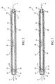
- FIG. 2 which is 2 is a cross-sectional view of a filter assembly 10 which does not form part of the present invention
- the filter assembly includes a housing 12 typically formed of a suitable polymer and having a cylindrical shape. Of course, other materials and shapes are contemplated.
- Housing 12 includes axially opposed first and second ends 14,16 and has an inner diameter defined by an inner wall 18 thereof.
- gas is carried from the patient circuit into first end 14 via a sampling line 32 connected to the first end.
- the gas passes through a channel 28 defined in housing 12 and exits second end 16, where it is provided to gas monitoring system 3 of FIG. 1 .
- the flow of gas through filter assembly 10 is indicated by arrows A.
- Lining inner wall 18 of housing 12 is a hydrophilic liner 20 for wicking moisture from expired gases and locking it away from the gas stream, as more fully described below.
- the hydrophilic liner 20 may be formed of a material suitable for accomplishing the wicking function, such as a porous plastic, having a pore size ranging from approximately 5 microns to approximately 50 microns.
- the hydrophilic liner 20 may be coupled with inner wall 18 of housing 12 by any technique known to those of ordinary skill in the art including, but not limited to, adhesives. Hydrophilic liner 20 not only absorbs moisture, but also acts as a smooth lining for housing 12, and thereby minimizes turbulence in the gas stream which may be caused by rough walls.
- a hydrophobic member 22 is provided at the downstream end of housing 12, i.e., proximate to second end 16.
- hydrophobic member 22 is a disc that spans the interior of the housing, i.e., extends across the inner diameter of channel 28. More specifically, hydrophobic member 22 has an outer diameter, defined by an outer surface 24 thereof that approximates the inner diameter of housing 12 such that the outer surface of the hydrophobic member is coupled with inner wall 18 of housing 12 in a gas-tight and fluid-tight arrangement.
- Such fluid-tight and gas-tight coupling mechanisms are known to those of ordinary skill in the art and, accordingly, will not be discussed further herein. In this manner, only gases passing through hydrophobic member 22 are permitted to reach the gas monitoring system 3, as more fully described below.
- An upstream surface 25 of the hydrophobic disk is in contact with a downstream edge 27 of the hydrophilic liner 20.
- hydrophilic liner 20 lines inner wall 18 of cylindrical housing 12 from first end 14 to a point near second end 16 where hydrophobic member 22 is located. It is to be understood, however, that hydrophilic liner 20 need not extend along the entire length of the housing, need not cover the entire surface of inner wall 18, and need not be formed from a single, unitary material. Rather, hydrophilic liner 20 can be formed from multiple pieces of material, and each portion or piece of the liner need not be formed from the same material. For example, the liner can be formed such that the absorbency of the material changes along the length of the housing.
- conduit 26 Positioned downstream of hydrophobic member 22 and in contact therewith is a conduit 26 for communicating the filtered gases from channel 28 to gas sensing mechanism 3 (see FIG.1 ). It is to be understood that conduit 26 need not be in direct contact with hydrophobic member 22 so long as it is operatively coupled to housing 12 for communicating the flow of gas from channel 28 to the sensing mechanism. Conduit 26 has an outer surface 30 thereof, the diameter of which substantially approximates the inner diameter defined by inner wall 18 of housing 12. In this manner, outer surface 30 of conduit 26 may be coupled with the inner wall of housing 12 in a gas-tight and fluid-tight manner, as known to those of ordinary skill in the art.
- gas sampling line 32 having an outer diameter, defined by an outer surface 34, which substantially approximates the inner diameter of hydrophilic liner 20.
- the inner diameter of hydrophilic liner 20 is defined by an inner surface 36 thereof.
- outer surface 34 of the gas sampling line 32 may be coupled in a gas-tight and fluid-tight manner with inner surface 36 of the hydrophilic liner in a gas-tight and fluid-tight arrangement, as known to those of ordinary skill in the art.
- the internal volume of the cylindrical housing 12, which is defined by the inner surface 36 of the hydrophilic liner 20, the upstream surface 25 of the hydrophobic disk 22 and an outlet 37 of the gas sampling line 32 is 1.5 ml (1.55 cc) or less.
- a patient expires gases containing liquids such as water, blood, mucus, medications and the like, into a nasal cannula (not shown), gas mask (not shown) or the like. Downstream of the nasal gala, or other suitable respiratory collection mechanism, the expired gases leaves a mainstream conduit 2 (see FIG. 1 ) and enters gas sampling line 32 such that at least a portion of the gases are directed toward filter assembly 10. Gas sampling line 32 forms a conduit through which the expired gases enter filter assembly 10 through outlet 37 thereof. Upon entering the filter assembly, the gases still contain liquids such as water, blood, mucus, medications and the like and/or particulates, which are desirably substantially filtered from the gases prior to the gases being directed toward gas monitoring system 3.
- hydrophilic liner 20 As the expired gases proceed through channel 28 of housing 12, moisture is wicked out of the gas stream by hydrophilic liner 20 lining inner wall 18 and is locked away from the gas stream. While hydrophilic liner 20 is capable of absorbing a substantial portion of the moisture from the gas stream, some moisture will remain in the stream. Thus, hydrophobic member 22 is provided as a second line of defense against moisture reaching the gas monitoring system. As the gas stream reaches the area proximate second end 16 of housing 12, the stream encounters hydrophobic ember 22. Because member 22 is formed of a hydrophobic material, gases will be permitted to pass therethrough but liquids will be substantially prevented from passing through the hydrophobic member. Instead, any liquid remaining in the gas stream will remain within channel 28 of cylindrical housing 12 and, preferably, will be absorbed by the downstream-most portion of hydrophilic liner 20.
- housing 12 As housing 12 is coupled in a gas-tight and fluid-tight arrangement with the outer surface of conduit 26, the only way that gases may exit channel 28 is through hydrophobic member 22. Thus, gases substantially free of liquids pass through the hydrophobic member 22, enter conduit 26 and proceed to the gas monitoring system to be monitored. In this manner, only gases substantially free of liquid condensate are permitted to reach the gas monitoring system. Further, because only inner wall 18 of housing 12 is lined with hydrophilic liner 20, the waveform of the exhaled gas sample is permitted to proceed substantially undisturbed from the point at which the sample is collected to the point at which the sensing mechanism readings are taken. Disturbance to the waveform which may be affected due to hydrophobic member 22 is of minimal consequence.
- filter assembly 38 includes a housing 12' typically formed of a suitable polymer and having a cylindrical shape. Housing 12' has axially opposed first and second ends 14', 16' and an inner diameter defined by an inner wall 18' thereof. Lining inner wall 18' is a hydrophilic liner 20' for wicking moisture from expired gases and locking it away from the gas stream.
- hydrophilic liner 20' be formed of a material suitable for accomplishing the wicking function, such as a porous plastic, having a pore size ranging from approximately 5 microns to approximately 50 microns. As discussed above, hydrophilic liner 20' not only absorbs moisture but also acts as a smooth lining for housing 12', and thereby minimizes the turbulence effects on the gas stream caused by rough walls.
- absorbent layer 40 Disposed between inner wall 18' of housing 12' and hydrophilic liner 20' is an absorbent layer 40.
- absorbent layer 40 has a thickness that is less than the thickness of hydrophilic liner 20' and is formed of an absorbent material having a greater absorbance than hydrophilic liner 20'.
- the absorbent layer can be as thick or thicker than the hydrophilic layer. Also, the absorbency of the absorbent layer need not be greater than that of the hydrophilic layer.
- Absorbent layer 40 is coupled with inner wall 18' of housing 12' by any technique known to those of ordinary skill in the art including, but not limited to, adhesives.
- hydrophilic liner 20' is coupled with the absorbent layer 40 by any known technique, e.g., hydrophilic adhesives.
- absorbent layer 40 lines inner wall 18' of housing 12' from first end 14' to a point where hydrophobic disk 22' is located, which is proximate second end 16'.
- hydrophilic liner 20' lines the absorbent layer 40' along substantially the entire length of the absorbent layer. It is to be understood, however, that absorbent layer 40 need not extend along the entire length of the housing, need not cover the entire surface of inner wall 18, and need not be formed from a single, unitary material. Rather, absorbent layer 40 can be formed from multiple pieces of material, and each portion or piece of the absorbent layer need not be formed from the same material. For example, the absorbent layer can be formed such that the absorbency of the material changes along the length of the housing or is maximized where it is more likely that condensation will gather.
- a hydrophobic member 22' is positioned proximate second end 16' of housing 12'.
- Hydrophobic member 22' has an outer diameter, defined by an outer surface 24' thereof that approximates the inner diameter of the cylindrical housing 12' such that outer surface 24' is coupled with inner wall 18' of the cylindrical housing 12' in a gas-tight and fluid-tight arrangement, as known to those of ordinary skill in the art. In this manner, only gases passing through the hydrophobic member 22' are permitted to reach the sensing mechanism.
- an upstream surface 25' of the hydrophobic member is in contact with a downstream edge 27' of hydrophilic liner 20' and a downstream edge 42 of absorbent layer 40'.
- the present invention also contemplates that there need not be direct contact between these members.
- conduit 26' Positioned downstream of the hydrophobic member 22' and in contact therewith is a conduit 26' for communicating the filtered gases from housing 12' to the sensing mechanism. It is to be understood that conduit 26' need not be in direct contact with hydrophobic member 22', so long as it is operatively coupled to housing 12' for communicating the flow of gas from channel 28' to the sensing mechanism.
- An outer surface 30' of conduit 26' is coupled in a gas-tight and fluid-tight manner to the inner wall of housing 12' as described above in relation to FIG. 2 .
- gas sampling line 32' Coupled with first end 14', of housing 12', is a gas sampling line 32', An outer surface 34' of gas sampling line 32' is coupled in a gas-tight and fluid-tight manner to an inner surface 36' of hydraphilic liner 20' as described above in relation to FIG. 2 .
- a patient's expired gases enter gas sampling line 26' and filter assembly 38 as described above with reference to FIGS. 1 and 2 .
- moisture is wicked out of the gas stream by hydrophilic liner 20' and locked away from the gas stream.
- liquids passing through hydrophilic liner 20' are further wicked therefrom and locked away from the gas stream by absorbent layer 40. In this manner, more liquid may be locked away from the gas stream than in the filter of FIG. 2 .
- hydrophilic liner 20' and absorbent layer 40 are capable of absorbing a substantial portion of the moisture from the gas stream, some moisture will remain in the stream.
- hydrophobic member 22' is provided as a second line of defense against moisture reaching the sensing mechanism.
- hydrophobic member 22' is formed of a hydrophobic material, gases will be permitted to pass therethrough but liquids will be substantially prevented from passing through the hydrophobic member 22'. Instead, any liquid remaining in the gas stream will remain within channel 28' and, preferably, will be absorbed by the downstream-most portions of hydrophilic liner 20' and absorbent layer 40.
- housing 12' As housing 12' is coupled in a gas-tight and fluid-tight arrangement with conduit 26', the only way that gases may exit housing 12 is through the hydrophobic member 22'.
- gases substantially free of liquids pass through the hydrophobic member 22', enter conduit 26' and proceed to the gas monitoring system to be monitored. In this manner, only gases substantially free of liquid condensate are permitted to reach the sensing mechanism.
- the waveform of the exhaled gas sample is permitted to proceed substantially undisturbed from the point at which the sample is collected to the point at which the sensing mechanism readings are taken. Disturbance to the waveform which may be affected due to the hydrophobic member 22' is of minimal consequence.
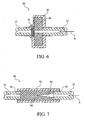
- FIG. 4 is a cross-sectional view of a portion of a third embodiment of the filter assembly 50 which does not form part of the present invention.
- Filter assembly 50 includes a housing 52 connected to a sampling line 32 and to a exit sampling line 33.
- a hydrophilic member 54 is disposed in the housing between sampling line 32 and housing 52.
- a hydrophobic member 56 is provided across the diameter of the housing.
- Sealing elements 58 are provided at each end of the housing to connect the housing the inlet and outlet lines.
- Housing 52 can be made from any suitable material, such as plastic, rubber, or silicon.
- the housing can be formed, at least in part, from an absorbent material or a gas drying material that is able to remove water/fluid from the gas, such as NAFION ® produced by DuPont.
- the filter assembly of Figure 4 is generally similar to that shown in FIG. 2 , except that hydrophilic member 54 is disposed between sampling line 32 and the housing 52 so that only a fraction of the hydrophilic member is exposed to the gas stream, which is indicated by arrow A. Hydrophilic member 54 is positioned relative the flow of gas A such that the flow of gas impacts on the hydrophobic member. Gas passes through the hydrophobic member, but water and other liquid does not. Hydrophilic member 54 is positioned relative to hydrophobic member 56 such that any water or other liquid that accumulates on the surface to the hydrophilic member migrates to hydrophilic member 54.
- Gap 60 is maintained between an end 62 of sampling line 32 and hydrophobic member 56.
- Gap 60 can be any size so long as water, or some other liquid depending on the liquid that is carried in gas stream A, is able to pass to hydrophilic member 54. This makes use of the wicking property of the hydrophilic member in that liquid that reaches the hydrophilic member is absorbed into the hydrophilic member and wicked away from hydrophobic member 56.
- the volume of hydrophilic member 54 is selected such that it is large enough to hold the quantity of water that may accumulate over its operating life.
- hydrophobic member 56 has a width between 0.254 to 1.524 mm (10 to 60 thousandths of an inch).
- the inside diameter of the sampling line an housing 52 should be sufficiently small to minimize mixing of the flowing gases as they travel through the filter assembly so that the signal fidelity/rise time is maintained.
- FIG. 5 is a cross-sectional view of a portion of a filter assembly 70 that is similar in many respects to the filter assembly of FIG. 4 .
- housing 72 includes a sample cell portion 74, such that the filter assembly is integral will the sample cell housing. That is, sample cell portion 74 houses the structures of the sample cell, which is the portion of the sampling system where the constituents of the gas are measured using irradiated energy or any conventional gas measurement technique.
- An example of an integrated filter and sample cell is taught in published PCT Appln. No PCTIUS03/31916 (Publication No. WO 2004/33062 ).
- FIG. 6 is a cross-sectional view of a portion of a filter assembly 80 which does not form part of the present invention.
- a housing 82 contains a mass of hydrophilic material 84 as the hydrophilic member.
- the large mass of hydrophilic material 84 disposed proximate to hydrophobic member 56 facilitates wicking of liquids from the hydrophobic member.
- hydrophobic member 56 and hydrophilic member 54 and 84 are circular or cylindrical-shaped. It is to be understood that other shapes for these components are contemplated.
- FIG. 7 is a cross-sectional view of a portion of a filter assembly 90 which does not form part of the present invention.
- the filter assembly includes a housing 92 that contains only a hydrophilic member 94. There is no hydrophobic member in this filter.
- Hydrophilic member 94 is relatively porous to allow gas to pass through it while also being sufficiently absorbent to remove any moisture in the gas as it passed through the hydrophilic member.
- a recess 96 is provided in the end of hydrophilic member 94 so that a relatively large surface area of the hydrophilic member is exposed to the incoming gas stream A. Providing a recess to increase the surface area of the hydrophilic member exposed to the incoming gas stream maximizes the ability of the hydrophilic member to capture contaminants/particulates while minimizing the pressure drop in the gas stream caused by the presence of the hydrophilic member.
- recess 96 has a cone-shaped. It is to be understood, however, that other configurations for the recess, such as triangular or star-shaped maybe possible.
- the hydrophilic member and housing can also have configurations other than the cylindrical shape shown in FIG. 7 .
Landscapes
- Health & Medical Sciences (AREA)
- Life Sciences & Earth Sciences (AREA)
- Veterinary Medicine (AREA)
- Pulmonology (AREA)
- Public Health (AREA)
- General Health & Medical Sciences (AREA)
- Animal Behavior & Ethology (AREA)
- Engineering & Computer Science (AREA)
- Biomedical Technology (AREA)
- Heart & Thoracic Surgery (AREA)
- Surgery (AREA)
- Molecular Biology (AREA)
- Medical Informatics (AREA)
- Pathology (AREA)
- Biophysics (AREA)
- Physics & Mathematics (AREA)
- Physiology (AREA)
- Emergency Medicine (AREA)
- Anesthesiology (AREA)
- Hematology (AREA)
- Sampling And Sample Adjustment (AREA)
- Measurement Of The Respiration, Hearing Ability, Form, And Blood Characteristics Of Living Organisms (AREA)
- External Artificial Organs (AREA)
- Removal Of Floating Material (AREA)
- Infusion, Injection, And Reservoir Apparatuses (AREA)
Abstract
Description
- The present invention relates generally to a sidestream gas monitoring system for monitoring a patient's medical condition, and, in particular, to a filter assembly for use in a sidestream monitoring system that separates undesired liquid components from respiratory gases to be monitored.
- During medical treatment, it is often desirable to monitor and analyze a patient's exhalations to determine the gaseous composition of the exhalate. For instance, monitoring the carbon dioxide (CO2 content of a patient's exhalations is often desirable. Typically, the carbon dioxide (or other gaseous) content of a patient's exhalation is monitored by transferring a portion, or sample, of the patient's expired gases to a suitable sensing mechanism and monitoring system.
- Monitoring of exhaled gases may be accomplished utilizing either mainstream or sidestream monitoring systems. In a mainstream monitoring system, the gaseous content of a patient's exhalations is measured in-situ in the patient circuit or conduit coupled to the patient's airway. In a sidestream monitoring system, on the other hand, the gas sample is transported from the patient circuit through a gas sampling line to a sensing mechanism located some distance from the main patient circuit for monitoring. As a patient's expired gases are typically fully saturated with water vapour at about 35°C, a natural consequence of the gas transport is condensation of the moisture present in the warm, moist, expired gases.
- Accurate analysis of the gaseous composition of a patient's exhalation is dependent upon a number of factors including collection of a gaseous sample that is substantially free of liquid condensate, which might distort the results of the analysis. As an expired gas sample cools during transport through the gas sampling line to the sensing mechanism in a sidestream monitoring system, the water vapour contained in the sample may condense into liquid, i.e., condensate. The liquid i.e., condensate, if permitted to reach the sensing mechanism, can have a detrimental effect on the functioning thereof and may lead to inaccurate monitoring results. Condensed liquid in the gas sampling line may also contaminate subsequent expired gas samples by being re-entrained into such subsequent samples.
- In addition to the condensate, it is not uncommon to have other undesirable liquids, such as blood, mucus, medications, and the like, contained in the expired gas sample. Each of these liquids, if present in the gas sample to be monitored, may render analytical results that do not accurately reflect the patient's medical status.
- There are numerous techniques for separating undesired liquids from the patient's expired gas stream to protect the gas sensing mechanism. For instance, it is known to place a moisture trap between the patient and the sensing mechanism to separate moisture from the exhalation gas before it enters the sensing mechanism. The challenge, however, is to achieve the separation without affecting the characteristics of the parameters being measured, e.g., the waveform of the gas to be monitored.
- By way of example, carbon dioxide (CO2) is effectively present only in the patient's expired gases. Therefore, the CO2 in an exhaled gas sample, transported through a gas sampling line to the sensing mechanism, fluctuates according to the CO2 present at the point at which the sample is taken. Disturbances in this fluctuation, i.e., in the CO2 waveform, are undesirable because any such disturbance can affect the accuracy of the CO2 measurement and the graphical display of the waveform. For this reason, removal of liquids from the exhaled gas sample is desirably accomplished in such a way that it does not substantially disturb the CO2 waveform. Unfortunately, conventional moisture traps often disturb the waveform to a substantial degree.
- Various other techniques have been employed to filter the expired gas stream of the undesired condensate while attempting to permit the waveform to be transported undisturbed. Such techniques include absorbents for wicking condensate out of the gas, centrifugal filters, desiccants, hydrophobic membranes for filtering gases and hydrophilic membranes for filtering liquids. While each of these techniques has its advantages, each has its drawbacks as well. Each of the techniques listed above can remove a portion of the liquid condensate, but none is foolproof, except, perhaps, for those using a hydrophobic filter. A consequence, a portion of the liquid condensate may still reach the sensing mechanism in many conventional filters. On the other hand, conventional filters that use a hydrophobic filter, can disturb the waveform beyond acceptable levels. Accordingly, a suitable filter that does not substantially disturb the waveform of expired gases and while substantially separating moisture from the gas sample and while minimizing deadspace would be advantageous.
-
US5131387 discloses a moisture trap for use in a patient monitoring system including a passageway containing a hydrophilic medium and a hydrophobic member positioned in the flow path to interrupt the flow path when the hydrophilic material becomes saturated and can no longer pick up moisture. -
US6375854 discloses a filter containing a hydrophilic filter and a hydrophobic filter. - Accordingly, it is an obj ect of the present invention to provide a filter assembly that overcomes the shortcomings of conventional filter assemblies. This object is achieved according to one embodiment of the present invention by providing a filter assembly for use in a sidestream gas sampling assembly comprising: a housing having an inlet, an outlet, and an inner wall defining a channel through the housing from the inlet to the outlet; a hydrophobic member disposed across the channel at a location proximate to the outlet; a hydrophilic liner disposed on the inner wall; and an absorbent layer positioned between the inner wall and the hydrophilic liner.
- In use, expired gases enter the filter assembly through the gas sampling line and proceed through the housing. The hydrophilic liner wicks moisture out of the expired gases and absorbs such liquids preventing them from reaching the gas monitoring system. The gases, and any moisture not absorbed by the hydrophilic liner, proceed through the housing to the downstream end where they encounter the hydrophobic member. The hydrophobic member permits the passage of gases therethrough but substantially prevents the passage of liquids. Thus, even moisture that did not get absorbed by the hydrophilic liner is prevented from reaching the sensing mechanism as it is not permitted to pass through the hydrophobic member. In this manner, only gases substantially free of liquid condensate are permitted to reach the gas monitoring system. Further, because only the inner perimeter of the cylindrical housing is lined with filter material until the gases reach the hydrophobic member, the waveform of the exhaled gas sample is permitted to proceed substantially undisturbed from the point at which the sample is collected to the point at which the sensing mechanism readings are taken. Disturbance to the waveform which may be caused by the hydrophobic disk is minimal.
- The present invention also pertains to sidestream gas monitoring system that includes either of the above-described filter assembly embodiments.
- These and other objects, features and characteristics of the present invention, as well as the methods of operation and functions of the related elements of structure and the combination of parts and economies of manufacture, will become more apparent upon consideration of the following description and the appended claims with reference to the accompanying drawings, all of which form a part of this specification, wherein like reference numerals designate corresponding parts in the various figures. It is to be expressly understood, however, that the drawings are for the purpose of illustration and description only and are not intended as a definition of the limits of the invention. As used in the specification and in the claims, the singular form of "a", "an", and "the" include plural referents unless the context clearly dictates otherwise.
-
-
FIG. 1 is a schematic view of a sidestream gas monitoring system including a filter assembly according to the principals of the present invention; -
FIG. 2 is a cross-sectional view of a filter assembly which does not form part of the present invention; -
FIG. 3 is a cross-sectional view of an embodiment of the filter assembly; -
FIG. 4 is a cross-sectional view of a portion of a filter assembly which does not form part of the present invention; -
FIG. 5 is a cross-sectional view of a portion of a filter assembly which does not form part of the present invention; -
FIG. 6 is a cross-sectional view of a filter assembly which does not form part of the present invention; and -
FIG. 7 is a cross-sectional view of a portion of a filter assembly which does not form part of the present invention. - Referring to the drawings in general and initially to
FIG. 1 , in particular, a side stream gas monitoring system 1 including afilter assembly 10 is illustrated. Gas monitoring system includes asampling line 32 that is coupled to apatient circuit 2, which is, in turn, in connected to an airway of patient (not shown) so that a portion of the gas in the patient circuit is diverted intosampling line 32.Filter assembly 10 coupled to an end of the sample line distal from the patient circuit and proximate to a gas monitoring system, generally indicated at 3. - The
gas monitoring system 3 may be any conventional sidestream gas monitoring system, which typically includes a sample cell 4 and a system for measuring the constituents of the gas within the sample cell. Such a system may include, for example, aradiation emitter 5 andreceiver 6, which detects the gas constituents within the sample cell using well know radiation absorption techniques. The present invention also contemplates using any suitable technique to attach the gas monitoring system to the airway of the patient. For example, an airway adapter connected to the patient circuit with a sampling line may be used. This configuration is shown inFIG. 1 . Alternatively, a nasal cannula can be used to connect the sampling line to the airway of the patient. - Referring now to
FIG. 2 , which is 2 is a cross-sectional view of afilter assembly 10 which does not form part of the present invention, the filter assembly includes ahousing 12 typically formed of a suitable polymer and having a cylindrical shape. Of course, other materials and shapes are contemplated.Housing 12 includes axially opposed first and second ends 14,16 and has an inner diameter defined by aninner wall 18 thereof. During normal use, gas is carried from the patient circuit intofirst end 14 via asampling line 32 connected to the first end. The gas passes through achannel 28 defined inhousing 12 and exitssecond end 16, where it is provided togas monitoring system 3 ofFIG. 1 . The flow of gas throughfilter assembly 10 is indicated by arrows A. - Lining
inner wall 18 ofhousing 12 is ahydrophilic liner 20 for wicking moisture from expired gases and locking it away from the gas stream, as more fully described below. Thehydrophilic liner 20 may be formed of a material suitable for accomplishing the wicking function, such as a porous plastic, having a pore size ranging from approximately 5 microns to approximately 50 microns. Thehydrophilic liner 20 may be coupled withinner wall 18 ofhousing 12 by any technique known to those of ordinary skill in the art including, but not limited to, adhesives.Hydrophilic liner 20 not only absorbs moisture, but also acts as a smooth lining forhousing 12, and thereby minimizes turbulence in the gas stream which may be caused by rough walls. - A
hydrophobic member 22 is provided at the downstream end ofhousing 12, i.e., proximate tosecond end 16. In the illustrated arrangement,hydrophobic member 22 is a disc that spans the interior of the housing, i.e., extends across the inner diameter ofchannel 28. More specifically,hydrophobic member 22 has an outer diameter, defined by anouter surface 24 thereof that approximates the inner diameter ofhousing 12 such that the outer surface of the hydrophobic member is coupled withinner wall 18 ofhousing 12 in a gas-tight and fluid-tight arrangement. Such fluid-tight and gas-tight coupling mechanisms are known to those of ordinary skill in the art and, accordingly, will not be discussed further herein. In this manner, only gases passing throughhydrophobic member 22 are permitted to reach thegas monitoring system 3, as more fully described below. Anupstream surface 25 of the hydrophobic disk is in contact with adownstream edge 27 of thehydrophilic liner 20. - In the illustrated arrangement,
hydrophilic liner 20 linesinner wall 18 ofcylindrical housing 12 fromfirst end 14 to a point nearsecond end 16 wherehydrophobic member 22 is located. It is to be understood, however, thathydrophilic liner 20 need not extend along the entire length of the housing, need not cover the entire surface ofinner wall 18, and need not be formed from a single, unitary material. Rather,hydrophilic liner 20 can be formed from multiple pieces of material, and each portion or piece of the liner need not be formed from the same material. For example, the liner can be formed such that the absorbency of the material changes along the length of the housing. - Positioned downstream of
hydrophobic member 22 and in contact therewith is aconduit 26 for communicating the filtered gases fromchannel 28 to gas sensing mechanism 3 (seeFIG.1 ). It is to be understood thatconduit 26 need not be in direct contact withhydrophobic member 22 so long as it is operatively coupled tohousing 12 for communicating the flow of gas fromchannel 28 to the sensing mechanism.Conduit 26 has anouter surface 30 thereof, the diameter of which substantially approximates the inner diameter defined byinner wall 18 ofhousing 12. In this manner,outer surface 30 ofconduit 26 may be coupled with the inner wall ofhousing 12 in a gas-tight and fluid-tight manner, as known to those of ordinary skill in the art. - Coupled with
first end 14 ofhousing 12 isgas sampling line 32 having an outer diameter, defined by anouter surface 34, which substantially approximates the inner diameter ofhydrophilic liner 20. The inner diameter ofhydrophilic liner 20 is defined by aninner surface 36 thereof. Accordingly,outer surface 34 of thegas sampling line 32 may be coupled in a gas-tight and fluid-tight manner withinner surface 36 of the hydrophilic liner in a gas-tight and fluid-tight arrangement, as known to those of ordinary skill in the art. - The internal volume of the
cylindrical housing 12, which is defined by theinner surface 36 of thehydrophilic liner 20, theupstream surface 25 of thehydrophobic disk 22 and anoutlet 37 of thegas sampling line 32 is 1.5 ml (1.55 cc) or less. - In operation, a patient expires gases containing liquids such as water, blood, mucus, medications and the like, into a nasal cannula (not shown), gas mask (not shown) or the like. Downstream of the nasal connula, or other suitable respiratory collection mechanism, the expired gases leaves a mainstream conduit 2 (see
FIG. 1 ) and entersgas sampling line 32 such that at least a portion of the gases are directed towardfilter assembly 10.Gas sampling line 32 forms a conduit through which the expired gases enterfilter assembly 10 throughoutlet 37 thereof. Upon entering the filter assembly, the gases still contain liquids such as water, blood, mucus, medications and the like and/or particulates, which are desirably substantially filtered from the gases prior to the gases being directed towardgas monitoring system 3. - As the expired gases proceed through
channel 28 ofhousing 12, moisture is wicked out of the gas stream byhydrophilic liner 20 lininginner wall 18 and is locked away from the gas stream. Whilehydrophilic liner 20 is capable of absorbing a substantial portion of the moisture from the gas stream, some moisture will remain in the stream. Thus,hydrophobic member 22 is provided as a second line of defense against moisture reaching the gas monitoring system. As the gas stream reaches the area proximatesecond end 16 ofhousing 12, the stream encountershydrophobic ember 22. Becausemember 22 is formed of a hydrophobic material, gases will be permitted to pass therethrough but liquids will be substantially prevented from passing through the hydrophobic member. Instead, any liquid remaining in the gas stream will remain withinchannel 28 ofcylindrical housing 12 and, preferably, will be absorbed by the downstream-most portion ofhydrophilic liner 20. - As
housing 12 is coupled in a gas-tight and fluid-tight arrangement with the outer surface ofconduit 26, the only way that gases may exitchannel 28 is throughhydrophobic member 22. Thus, gases substantially free of liquids pass through thehydrophobic member 22, enterconduit 26 and proceed to the gas monitoring system to be monitored. In this manner, only gases substantially free of liquid condensate are permitted to reach the gas monitoring system. Further, because onlyinner wall 18 ofhousing 12 is lined withhydrophilic liner 20, the waveform of the exhaled gas sample is permitted to proceed substantially undisturbed from the point at which the sample is collected to the point at which the sensing mechanism readings are taken. Disturbance to the waveform which may be affected due tohydrophobic member 22 is of minimal consequence. - Referring now to
FIG. 3 , an embodiment of a filter assembly according to the principles of the present invention is illustrated and denoted generally byreference numeral 38. Likefilter assembly 10 ofFIG. 2 ,filter assembly 38 includes a housing 12' typically formed of a suitable polymer and having a cylindrical shape. Housing 12' has axially opposed first and second ends 14', 16' and an inner diameter defined by an inner wall 18' thereof. Lining inner wall 18' is a hydrophilic liner 20' for wicking moisture from expired gases and locking it away from the gas stream. The present invention contemplates that hydrophilic liner 20' be formed of a material suitable for accomplishing the wicking function, such as a porous plastic, having a pore size ranging from approximately 5 microns to approximately 50 microns. As discussed above, hydrophilic liner 20' not only absorbs moisture but also acts as a smooth lining for housing 12', and thereby minimizes the turbulence effects on the gas stream caused by rough walls. - Disposed between inner wall 18' of housing 12' and hydrophilic liner 20' is an
absorbent layer 40. In an exemplary embodiment of the present invention,absorbent layer 40 has a thickness that is less than the thickness of hydrophilic liner 20' and is formed of an absorbent material having a greater absorbance than hydrophilic liner 20'. The present invention also contemplates that the absorbent layer can be as thick or thicker than the hydrophilic layer. Also, the absorbency of the absorbent layer need not be greater than that of the hydrophilic layer. -
Absorbent layer 40 is coupled with inner wall 18' of housing 12' by any technique known to those of ordinary skill in the art including, but not limited to, adhesives. Similarly, hydrophilic liner 20' is coupled with theabsorbent layer 40 by any known technique, e.g., hydrophilic adhesives. - In the illustrated exemplary embodiment,
absorbent layer 40 lines inner wall 18' of housing 12' from first end 14' to a point where hydrophobic disk 22' is located, which is proximate second end 16'. In addition, hydrophilic liner 20' lines the absorbent layer 40' along substantially the entire length of the absorbent layer. It is to be understood, however, thatabsorbent layer 40 need not extend along the entire length of the housing, need not cover the entire surface ofinner wall 18, and need not be formed from a single, unitary material. Rather,absorbent layer 40 can be formed from multiple pieces of material, and each portion or piece of the absorbent layer need not be formed from the same material. For example, the absorbent layer can be formed such that the absorbency of the material changes along the length of the housing or is maximized where it is more likely that condensation will gather. - As in the filter of
Figure 2 , a hydrophobic member 22' is positioned proximate second end 16' of housing 12'. Hydrophobic member 22' has an outer diameter, defined by an outer surface 24' thereof that approximates the inner diameter of the cylindrical housing 12' such that outer surface 24' is coupled with inner wall 18' of the cylindrical housing 12' in a gas-tight and fluid-tight arrangement, as known to those of ordinary skill in the art. In this manner, only gases passing through the hydrophobic member 22' are permitted to reach the sensing mechanism. In the illustrated embodiment, an upstream surface 25' of the hydrophobic member is in contact with a downstream edge 27' of hydrophilic liner 20' and adownstream edge 42 of absorbent layer 40'. However, the present invention also contemplates that there need not be direct contact between these members. - Positioned downstream of the hydrophobic member 22' and in contact therewith is a conduit 26' for communicating the filtered gases from housing 12' to the sensing mechanism. It is to be understood that conduit 26' need not be in direct contact with hydrophobic member 22', so long as it is operatively coupled to housing 12' for communicating the flow of gas from channel 28' to the sensing mechanism. An outer surface 30' of conduit 26' is coupled in a gas-tight and fluid-tight manner to the inner wall of housing 12' as described above in relation to
FIG. 2 . - Coupled with first end 14', of housing 12', is a gas sampling line 32', An outer surface 34' of gas sampling line 32' is coupled in a gas-tight and fluid-tight manner to an inner surface 36' of hydraphilic liner 20' as described above in relation to
FIG. 2 . - In operation, a patient's expired gases enter gas sampling line 26' and filter
assembly 38 as described above with reference toFIGS. 1 and2 . As the expired gases proceed through the internal volume of housing 12', moisture is wicked out of the gas stream by hydrophilic liner 20' and locked away from the gas stream. Further, liquids passing through hydrophilic liner 20' are further wicked therefrom and locked away from the gas stream byabsorbent layer 40. In this manner, more liquid may be locked away from the gas stream than in the filter ofFIG. 2 . While hydrophilic liner 20' andabsorbent layer 40 are capable of absorbing a substantial portion of the moisture from the gas stream, some moisture will remain in the stream. Thus, hydrophobic member 22' is provided as a second line of defense against moisture reaching the sensing mechanism. Because hydrophobic member 22' is formed of a hydrophobic material, gases will be permitted to pass therethrough but liquids will be substantially prevented from passing through the hydrophobic member 22'. Instead, any liquid remaining in the gas stream will remain within channel 28' and, preferably, will be absorbed by the downstream-most portions of hydrophilic liner 20' andabsorbent layer 40. - As housing 12' is coupled in a gas-tight and fluid-tight arrangement with conduit 26', the only way that gases may exit
housing 12 is through the hydrophobic member 22'. Thus, gases substantially free of liquids pass through the hydrophobic member 22', enter conduit 26' and proceed to the gas monitoring system to be monitored. In this manner, only gases substantially free of liquid condensate are permitted to reach the sensing mechanism. Further, because only inner wall 18' of housing 12' is lined with hydrophilic liner 20', the waveform of the exhaled gas sample is permitted to proceed substantially undisturbed from the point at which the sample is collected to the point at which the sensing mechanism readings are taken. Disturbance to the waveform which may be affected due to the hydrophobic member 22' is of minimal consequence. -
FIG. 4 is a cross-sectional view of a portion of a third embodiment of thefilter assembly 50 which does not form part of the present invention.Filter assembly 50 includes ahousing 52 connected to asampling line 32 and to aexit sampling line 33. Ahydrophilic member 54 is disposed in the housing betweensampling line 32 andhousing 52. Ahydrophobic member 56 is provided across the diameter of the housing.Sealing elements 58 are provided at each end of the housing to connect the housing the inlet and outlet lines.Housing 52 can be made from any suitable material, such as plastic, rubber, or silicon. The housing can be formed, at least in part, from an absorbent material or a gas drying material that is able to remove water/fluid from the gas, such as NAFION® produced by DuPont. - The filter assembly of
Figure 4 is generally similar to that shown inFIG. 2 , except thathydrophilic member 54 is disposed betweensampling line 32 and thehousing 52 so that only a fraction of the hydrophilic member is exposed to the gas stream, which is indicated by arrowA. Hydrophilic member 54 is positioned relative the flow of gas A such that the flow of gas impacts on the hydrophobic member. Gas passes through the hydrophobic member, but water and other liquid does not.Hydrophilic member 54 is positioned relative tohydrophobic member 56 such that any water or other liquid that accumulates on the surface to the hydrophilic member migrates tohydrophilic member 54. - To allow the water to migrate along the surface of
hydrophobic member 56 to the hydrophilic member, agap 60 is maintained between anend 62 ofsampling line 32 andhydrophobic member 56.Gap 60 can be any size so long as water, or some other liquid depending on the liquid that is carried in gas stream A, is able to pass tohydrophilic member 54. This makes use of the wicking property of the hydrophilic member in that liquid that reaches the hydrophilic member is absorbed into the hydrophilic member and wicked away fromhydrophobic member 56. The volume ofhydrophilic member 54 is selected such that it is large enough to hold the quantity of water that may accumulate over its operating life. - To minimize resistance and its resulting effect on signal fidelity and rise time,
hydrophobic member 56 has a width between 0.254 to 1.524 mm (10 to 60 thousandths of an inch). The inside diameter of the sampling line anhousing 52 should be sufficiently small to minimize mixing of the flowing gases as they travel through the filter assembly so that the signal fidelity/rise time is maintained. -
FIG. 5 is a cross-sectional view of a portion of afilter assembly 70 that is similar in many respects to the filter assembly ofFIG. 4 . The primary difference between these two arrangements resides in the structure ofhousing 72. In the filter ofFIG. 5 ,housing 72 includes asample cell portion 74, such that the filter assembly is integral will the sample cell housing. That is,sample cell portion 74 houses the structures of the sample cell, which is the portion of the sampling system where the constituents of the gas are measured using irradiated energy or any conventional gas measurement technique. An example of an integrated filter and sample cell is taught in published PCT Appln. NoPCTIUS03/31916 (Publication No.WO 2004/33062 -
FIG. 6 is a cross-sectional view of a portion of afilter assembly 80 which does not form part of the present invention. In this arrangement, ahousing 82 contains a mass ofhydrophilic material 84 as the hydrophilic member. The large mass ofhydrophilic material 84 disposed proximate tohydrophobic member 56 facilitates wicking of liquids from the hydrophobic member. In the arrangements shown inFIGS. 4-6 ,hydrophobic member 56 andhydrophilic member -
FIG. 7 is a cross-sectional view of a portion of afilter assembly 90 which does not form part of the present invention. In the arrangement, the filter assembly includes ahousing 92 that contains only ahydrophilic member 94. There is no hydrophobic member in this filter.Hydrophilic member 94 is relatively porous to allow gas to pass through it while also being sufficiently absorbent to remove any moisture in the gas as it passed through the hydrophilic member. - In the illustrated arrangement, a
recess 96 is provided in the end ofhydrophilic member 94 so that a relatively large surface area of the hydrophilic member is exposed to the incoming gas stream A. Providing a recess to increase the surface area of the hydrophilic member exposed to the incoming gas stream maximizes the ability of the hydrophilic member to capture contaminants/particulates while minimizing the pressure drop in the gas stream caused by the presence of the hydrophilic member. In the illustrated arrangement,recess 96 has a cone-shaped. It is to be understood, however, that other configurations for the recess, such as triangular or star-shaped maybe possible. In addition, the hydrophilic member and housing can also have configurations other than the cylindrical shape shown inFIG. 7 . - Although the invention has been described in detail for the purpose of illustration based on what is currently considered to be the most practical and preferred embodiment, it is to be understood that such detail is solely for the purpose and that the invention is not limited to the disclosed embodiment, but, on the contrary, is intended to cover modifications and equivalent arrangements that are within the scope of the appended claims. For example, it is to be understood that the present invention contemplates that, to the extent possible, one or more features of any embodiment can be combined with one or more features of any other embodiment.
Claims (17)
- A filter assembly (38) for use in a sidestream gas sampling assembly comprising:a housing (12') having an inlet, an outlet, and an inner wall defining a channel through the housing from the inlet to the outlet;a hydrophobic member (22') disposed across the channel at a location proximate to the outlet;a hydrophilic liner (20') disposed on the inner wall; andan absorbent layer (40) positioned between the inner wall and the hydrophilic liner.
- The filter assembly (3 8) of claim 1, wherein the absorbent layer (40) has a first edge that contacts a surface of the hydrophobic member (22').
- The filter assembly (38) of claim 1, wherein the absorbent layer (40) covers a majority of the inner wall extending between the inlet and the hydrophobic member.
- The filter assembly (38) of claim 1, wherein the absorbent layer (40) has a substantially smoother inner surface.
- The filter assembly (3 8) of claim 1, wherein the hydrophilic liner (20') covers a majority of the absorbent layer (40) extending between the inlet and the hydrophobic member (22').
- The filter assembly (38) of claim 1, wherein the hydrophilic liner (20') has a first edge that contacts a surface of the hydrophobic member (22').
- The filter assembly (38) of claim 1, wherein the hydrophilic liner (20') covers a majority of the inner wall extending between the inlet and the hydrophobic member (22').
- The filter assembly (38) of claim 1, further comprising a gas sampling line (32') coupled to the inlet.
- The filter assembly (38) of claim 8, further comprising an exit conduit (30') coupled to the outlet.
- The filter assembly (38) of claim 1, wherein the housing (12') is cylindrical and wherein the hydrophobic member (22') is disc-shaped.
- A sidestream gas monitoring system (1) comprising:(a) a sampling line (32') having a first end and a second end, wherein the sampling line is adapted to carry a flow of gas from a patient circuit;(b) a filter assembly (38) comprising:(i) a housing (12') having an inlet adapted to be coupled to the second end of the sampling line, an outlet, and an inner wall defining a channel through the housing (12') from the inlet to the outlet,(ii) a hydrophobic member (22') disposed across the channel at a location proximate to the outlet, and(iii) a hydrophilic liner (20') disposed on the inner wall;(c) a sample cell (4) operatively coupled to an outlet of the housing (12'); and(d) a detecting system (3) adapted to measure a constituent of gas contained within the sample cell, and(iv) an absorbent layer (40) positioned between the inner wall and the hydrophilic liner (20').
- The system (1) of claim 11, wherein the absorbent layer (40) has a first edge that contacts a surface of the hydrophobic member (22').
- The system (1) of claim 11, wherein the absorbent layer (40) covers a majority of the inner wall extending between the inlet and the hydrophobic member (22').
- The system (1) of claim 13, wherein the hydrophilic liner (20') covers a majority of the absorbent layer (40) extending between the inlet and the hydrophobic member (22').
- The system (1) of claim 11, wherein the hydrophilic liner (20') has a first edge that contacts a surface of the hydrophobic member (22').
- The system (1) of claim 11, wherein the hydrophilic liner (20') covers a majority of the inner wall extending between the inlet and the hydrophobic member (22').
- The system (1) of claims 11, wherein the housing (12') is cylindrical and wherein the hydrophobic member (22')is disc-shaped.
Applications Claiming Priority (3)
| Application Number | Priority Date | Filing Date | Title |
|---|---|---|---|
| US53876604P | 2004-01-23 | 2004-01-23 | |
| US11/039,749 US7137390B2 (en) | 2004-01-23 | 2005-01-19 | Liquid absorbing filter assembly and system using same |
| PCT/US2005/002136 WO2005072297A2 (en) | 2004-01-23 | 2005-01-20 | Liquid absorbing filter assembly and system using same |
Publications (3)
| Publication Number | Publication Date |
|---|---|
| EP1718369A2 EP1718369A2 (en) | 2006-11-08 |
| EP1718369A4 EP1718369A4 (en) | 2008-02-27 |
| EP1718369B1 true EP1718369B1 (en) | 2009-08-26 |
Family
ID=34798155
Family Applications (1)
| Application Number | Title | Priority Date | Filing Date |
|---|---|---|---|
| EP05711890A Expired - Lifetime EP1718369B1 (en) | 2004-01-23 | 2005-01-20 | Liquid absorbing filter assembly and system using same |
Country Status (5)
| Country | Link |
|---|---|
| US (1) | US7137390B2 (en) |
| EP (1) | EP1718369B1 (en) |
| AT (1) | ATE440642T1 (en) |
| DE (1) | DE602005016219D1 (en) |
| WO (1) | WO2005072297A2 (en) |
Families Citing this family (45)
| Publication number | Priority date | Publication date | Assignee | Title |
|---|---|---|---|---|
| US7549316B2 (en) * | 2002-10-08 | 2009-06-23 | Ric Investments, Llc. | Integrated sample cell and filter and system using same |
| US7597733B2 (en) * | 2004-01-23 | 2009-10-06 | Ric Investments, Llc | Liquid absorbing filter assembly and system |
| US9757052B2 (en) * | 2005-05-10 | 2017-09-12 | Oridion Medical (1987) Ltd. | Fluid drying mechanism |
| EP1924854B1 (en) * | 2005-08-16 | 2016-04-13 | Oridion Medical 1987 Ltd. | Breath sampling device and method for using same |
| US8177974B2 (en) | 2006-04-14 | 2012-05-15 | Emd Millipore Corporation | Disposable tangential flow filtration device holder |
| US7748280B2 (en) * | 2006-07-06 | 2010-07-06 | Ric Investments, Llc | Sidestream gas sampling system with closed sample circuit |
| US20080027344A1 (en) | 2006-07-27 | 2008-01-31 | Ric Investments, Llc | Modular sidestream gas sampling assembly |
| US20090025724A1 (en) * | 2007-07-16 | 2009-01-29 | Herron Jr Roy Howard | System for removal of water from a hose and the hygroscopic hose utilized |
| GB2455962A (en) | 2007-12-24 | 2009-07-01 | Ethicon Inc | Reinforced adhesive backing sheet, for plaster |
| EP2361641B2 (en) | 2008-03-05 | 2021-11-03 | KCI Licensing, Inc. | Dressing for applying reduced pressure to and collecting and storing fluid from a tissue site |
| SE532941C2 (en) * | 2008-09-15 | 2010-05-18 | Phasein Ab | Gas sampling line for breathing gases |
| US8454822B2 (en) | 2009-05-29 | 2013-06-04 | Emd Millipore Corporation | Disposable tangential flow filtration liner with sensor mount |
| US20110174711A1 (en) * | 2009-08-04 | 2011-07-21 | Millipore Corporation | Self Contained Disposable Tangential Flow Filtration Liner |
| US8814842B2 (en) | 2010-03-16 | 2014-08-26 | Kci Licensing, Inc. | Delivery-and-fluid-storage bridges for use with reduced-pressure systems |
| GB2488749A (en) | 2011-01-31 | 2012-09-12 | Systagenix Wound Man Ip Co Bv | Laminated silicone coated wound dressing |
| GB201106491D0 (en) | 2011-04-15 | 2011-06-01 | Systagenix Wound Man Ip Co Bv | Patterened silicone coating |
| CN202786257U (en) * | 2011-08-31 | 2013-03-13 | 通用电气健康护理生物科学股份公司 | Exhaust filtration device for bioreactor |
| EP2802304B1 (en) | 2011-12-16 | 2015-12-09 | KCI Licensing, Inc. | Releasable medical drapes |
| US10940047B2 (en) | 2011-12-16 | 2021-03-09 | Kci Licensing, Inc. | Sealing systems and methods employing a hybrid switchable drape |
| BR112015011271B1 (en) | 2012-11-16 | 2022-03-03 | 3M Innovative Properties Company | Surgical drape, system and method of manufacturing a surgical drape |
| GB201222770D0 (en) | 2012-12-18 | 2013-01-30 | Systagenix Wound Man Ip Co Bv | Wound dressing with adhesive margin |
| US10517892B2 (en) | 2013-10-22 | 2019-12-31 | Medtronic Minimed, Inc. | Methods and systems for inhibiting foreign-body responses in diabetic patients |
| EP3470030B1 (en) | 2013-10-28 | 2024-06-26 | Solventum Intellectual Properties Company | Hybrid sealing tape |
| WO2015065616A1 (en) | 2013-10-30 | 2015-05-07 | Kci Licensing, Inc. | Dressing with sealing and retention intereface |
| US9925092B2 (en) * | 2013-10-30 | 2018-03-27 | Kci Licensing, Inc. | Absorbent conduit and system |
| CN110652396B (en) | 2013-10-30 | 2021-11-23 | 3M创新知识产权公司 | Dressings with perforations of different sizes |
| EP3656362A1 (en) * | 2013-10-30 | 2020-05-27 | KCI Licensing, Inc. | Condensate absorbing and dissipating system related application |
| US9572948B2 (en) | 2013-12-20 | 2017-02-21 | General Electric Company | Liquid separator for removing a liquid from a sample of a breathing gas and airway adapter |
| US20150208952A1 (en) * | 2014-01-29 | 2015-07-30 | Oridion Medical 1987 Ltd. | Breath sampling tubes |
| US20150238119A1 (en) * | 2014-02-27 | 2015-08-27 | Oridion Medical 1987 Ltd. | Breath sampling tubes with array of reservoirs |
| CA2940730C (en) | 2014-02-28 | 2022-07-26 | Kci Licensing, Inc. | Hybrid drape having a gel-coated perforated mesh |
| US11026844B2 (en) | 2014-03-03 | 2021-06-08 | Kci Licensing, Inc. | Low profile flexible pressure transmission conduit |
| US10406266B2 (en) | 2014-05-02 | 2019-09-10 | Kci Licensing, Inc. | Fluid storage devices, systems, and methods |
| AU2015269359B2 (en) | 2014-06-05 | 2019-08-15 | Kci Licensing, Inc. | Dressing with fluid acquisition and distribution characteristics |
| US10279126B2 (en) * | 2014-10-07 | 2019-05-07 | Medtronic Minimed, Inc. | Fluid conduit assembly with gas trapping filter in the fluid flow path |
| DE102014014661B4 (en) | 2014-10-08 | 2022-10-13 | Drägerwerk AG & Co. KGaA | Device for removing and transporting a flow of breathing gas |
| WO2016100098A1 (en) | 2014-12-17 | 2016-06-23 | Kci Licensing, Inc. | Dressing with offloading capability |
| WO2016182977A1 (en) | 2015-05-08 | 2016-11-17 | Kci Licensing, Inc. | Low acuity dressing with integral pump |
| EP3741335B1 (en) | 2015-09-01 | 2023-05-24 | KCI Licensing, Inc. | Dressing with increased apposition force |
| WO2017048866A1 (en) | 2015-09-17 | 2017-03-23 | Kci Licensing, Inc. | Hybrid silicone and acrylic adhesive cover for use with wound treatment |
| US10178963B1 (en) * | 2016-06-09 | 2019-01-15 | Dynosense, Corp. | Gas collection apparatus and method to analyze a human breath sample |
| US11197949B2 (en) | 2017-01-19 | 2021-12-14 | Medtronic Minimed, Inc. | Medication infusion components and systems |
| US11964106B2 (en) * | 2017-12-21 | 2024-04-23 | Oridion Medical 1987 Ltd. | Bypass filter |
| DE102020117619A1 (en) | 2020-07-03 | 2022-01-20 | Drägerwerk AG & Co. KGaA | Sensor arrangement, medical device, expiration valve and method for determining a carbon dioxide concentration in a measurement gas |
| EP4701529A1 (en) * | 2023-04-27 | 2026-03-04 | Oridion Medical 1987 Ltd. | Capnography filter |
Family Cites Families (12)
| Publication number | Priority date | Publication date | Assignee | Title |
|---|---|---|---|---|
| US3631654A (en) * | 1968-10-03 | 1972-01-04 | Pall Corp | Gas purge device |
| US4031891A (en) * | 1975-11-03 | 1977-06-28 | Baxter Travenol Laboratories, Inc. | Air eliminating filter |
| US4262668A (en) * | 1979-04-06 | 1981-04-21 | Baxter Travenol Laboratories, Inc. | Fixed volume infusion device |
| US4424817A (en) * | 1981-07-01 | 1984-01-10 | Marquest Medical Products, Inc. | Syringe with means for automatically sealing a blood sample within the syringe |
| US4571244A (en) * | 1984-05-07 | 1986-02-18 | Biogenesis, Inc. | System for removing gas bubbles from liquids |
| US4938389A (en) * | 1988-11-03 | 1990-07-03 | Eye Research Institute Of Retina Foundation | Filter bottle |
| US5131387A (en) | 1990-05-09 | 1992-07-21 | Marquette Gas Analysis Corp. | Moisture trap |
| US5616158A (en) | 1995-05-15 | 1997-04-01 | Pryon Corporation | Moisture absorbing media filter |
| US6375854B2 (en) * | 1996-11-18 | 2002-04-23 | Douglas K. Beplate | Combined hydrophobic-hydrophilic filter for fluids |
| US6550347B2 (en) * | 2000-11-30 | 2003-04-22 | Bruce J. Bradley | Vacuum air component sampler |
| US6783573B2 (en) * | 2002-09-27 | 2004-08-31 | Welch Allyn Protocol, Inc. | Gas sampling system |
| US7121134B2 (en) | 2002-10-08 | 2006-10-17 | Ric Investments, Llc. | Integrated sample cell and filter and system using same |
-
2005
- 2005-01-19 US US11/039,749 patent/US7137390B2/en not_active Expired - Lifetime
- 2005-01-20 EP EP05711890A patent/EP1718369B1/en not_active Expired - Lifetime
- 2005-01-20 WO PCT/US2005/002136 patent/WO2005072297A2/en not_active Ceased
- 2005-01-20 DE DE602005016219T patent/DE602005016219D1/en not_active Expired - Lifetime
- 2005-01-20 AT AT05711890T patent/ATE440642T1/en not_active IP Right Cessation
Also Published As
| Publication number | Publication date |
|---|---|
| US20050161042A1 (en) | 2005-07-28 |
| EP1718369A4 (en) | 2008-02-27 |
| ATE440642T1 (en) | 2009-09-15 |
| WO2005072297A3 (en) | 2005-10-20 |
| EP1718369A2 (en) | 2006-11-08 |
| US7137390B2 (en) | 2006-11-21 |
| WO2005072297A2 (en) | 2005-08-11 |
| DE602005016219D1 (en) | 2009-10-08 |
Similar Documents
| Publication | Publication Date | Title |
|---|---|---|
| US7137390B2 (en) | Liquid absorbing filter assembly and system using same | |
| US8252080B2 (en) | Liquid absorbing filter assembly and system using same | |
| US8240187B2 (en) | Breath sampling device and method for using same | |
| US6044843A (en) | Moisture resistant airway adapter for monitoring constituent gases | |
| US4446869A (en) | Water absorbing trap to protect an infrared exhaled carbon dioxide apnea monitor of a patient's respiration | |
| US4558708A (en) | Patient's airway adapter to withdraw a patient's gas samples for testing free of sputum mucus and/or condensed water, by utilizing a hollow cylindrical hydrophobic liquid baffle | |
| US5857461A (en) | Multiple channel sample port | |
| US20080027344A1 (en) | Modular sidestream gas sampling assembly | |
| JP2013068630A (en) | Integrated sample cell and filter, and system using them | |
| EP2326246A1 (en) | Gas sampling line for respiratory gases | |
| US7121134B2 (en) | Integrated sample cell and filter and system using same | |
| EP3682800B1 (en) | Liquid separator for removing a liquid from a sample of a breathing gas and airway adapter | |
| CN121240822A (en) | Carbon dioxide chromatographic filter |
Legal Events
| Date | Code | Title | Description |
|---|---|---|---|
| PUAI | Public reference made under article 153(3) epc to a published international application that has entered the european phase |
Free format text: ORIGINAL CODE: 0009012 |
|
| 17P | Request for examination filed |
Effective date: 20060822 |
|
| AK | Designated contracting states |
Kind code of ref document: A2 Designated state(s): AT BE BG CH CY CZ DE DK EE ES FI FR GB GR HU IE IS IT LI LT LU MC NL PL PT RO SE SI SK TR |
|
| DAX | Request for extension of the european patent (deleted) | ||
| A4 | Supplementary search report drawn up and despatched |
Effective date: 20080124 |
|
| 17Q | First examination report despatched |
Effective date: 20080807 |
|
| GRAP | Despatch of communication of intention to grant a patent |
Free format text: ORIGINAL CODE: EPIDOSNIGR1 |
|
| GRAS | Grant fee paid |
Free format text: ORIGINAL CODE: EPIDOSNIGR3 |
|
| GRAA | (expected) grant |
Free format text: ORIGINAL CODE: 0009210 |
|
| AK | Designated contracting states |
Kind code of ref document: B1 Designated state(s): AT BE BG CH CY CZ DE DK EE ES FI FR GB GR HU IE IS IT LI LT LU MC NL PL PT RO SE SI SK TR |
|
| REG | Reference to a national code |
Ref country code: GB Ref legal event code: FG4D |
|
| REG | Reference to a national code |
Ref country code: CH Ref legal event code: EP |
|
| REG | Reference to a national code |
Ref country code: IE Ref legal event code: FG4D |
|
| REF | Corresponds to: |
Ref document number: 602005016219 Country of ref document: DE Date of ref document: 20091008 Kind code of ref document: P |
|
| LTIE | Lt: invalidation of european patent or patent extension |
Effective date: 20090826 |
|
| PG25 | Lapsed in a contracting state [announced via postgrant information from national office to epo] |
Ref country code: FI Free format text: LAPSE BECAUSE OF FAILURE TO SUBMIT A TRANSLATION OF THE DESCRIPTION OR TO PAY THE FEE WITHIN THE PRESCRIBED TIME-LIMIT Effective date: 20090826 Ref country code: SE Free format text: LAPSE BECAUSE OF FAILURE TO SUBMIT A TRANSLATION OF THE DESCRIPTION OR TO PAY THE FEE WITHIN THE PRESCRIBED TIME-LIMIT Effective date: 20090826 Ref country code: AT Free format text: LAPSE BECAUSE OF FAILURE TO SUBMIT A TRANSLATION OF THE DESCRIPTION OR TO PAY THE FEE WITHIN THE PRESCRIBED TIME-LIMIT Effective date: 20090826 Ref country code: IS Free format text: LAPSE BECAUSE OF FAILURE TO SUBMIT A TRANSLATION OF THE DESCRIPTION OR TO PAY THE FEE WITHIN THE PRESCRIBED TIME-LIMIT Effective date: 20091226 Ref country code: LT Free format text: LAPSE BECAUSE OF FAILURE TO SUBMIT A TRANSLATION OF THE DESCRIPTION OR TO PAY THE FEE WITHIN THE PRESCRIBED TIME-LIMIT Effective date: 20090826 |
|
| NLV1 | Nl: lapsed or annulled due to failure to fulfill the requirements of art. 29p and 29m of the patents act | ||
| PG25 | Lapsed in a contracting state [announced via postgrant information from national office to epo] |
Ref country code: SI Free format text: LAPSE BECAUSE OF FAILURE TO SUBMIT A TRANSLATION OF THE DESCRIPTION OR TO PAY THE FEE WITHIN THE PRESCRIBED TIME-LIMIT Effective date: 20090826 Ref country code: NL Free format text: LAPSE BECAUSE OF FAILURE TO SUBMIT A TRANSLATION OF THE DESCRIPTION OR TO PAY THE FEE WITHIN THE PRESCRIBED TIME-LIMIT Effective date: 20090826 Ref country code: PL Free format text: LAPSE BECAUSE OF FAILURE TO SUBMIT A TRANSLATION OF THE DESCRIPTION OR TO PAY THE FEE WITHIN THE PRESCRIBED TIME-LIMIT Effective date: 20090826 |
|
| PG25 | Lapsed in a contracting state [announced via postgrant information from national office to epo] |
Ref country code: BG Free format text: LAPSE BECAUSE OF FAILURE TO SUBMIT A TRANSLATION OF THE DESCRIPTION OR TO PAY THE FEE WITHIN THE PRESCRIBED TIME-LIMIT Effective date: 20091126 Ref country code: PT Free format text: LAPSE BECAUSE OF FAILURE TO SUBMIT A TRANSLATION OF THE DESCRIPTION OR TO PAY THE FEE WITHIN THE PRESCRIBED TIME-LIMIT Effective date: 20091228 Ref country code: CY Free format text: LAPSE BECAUSE OF FAILURE TO SUBMIT A TRANSLATION OF THE DESCRIPTION OR TO PAY THE FEE WITHIN THE PRESCRIBED TIME-LIMIT Effective date: 20090826 |
|
| PG25 | Lapsed in a contracting state [announced via postgrant information from national office to epo] |
Ref country code: EE Free format text: LAPSE BECAUSE OF FAILURE TO SUBMIT A TRANSLATION OF THE DESCRIPTION OR TO PAY THE FEE WITHIN THE PRESCRIBED TIME-LIMIT Effective date: 20090826 Ref country code: CZ Free format text: LAPSE BECAUSE OF FAILURE TO SUBMIT A TRANSLATION OF THE DESCRIPTION OR TO PAY THE FEE WITHIN THE PRESCRIBED TIME-LIMIT Effective date: 20090826 Ref country code: DK Free format text: LAPSE BECAUSE OF FAILURE TO SUBMIT A TRANSLATION OF THE DESCRIPTION OR TO PAY THE FEE WITHIN THE PRESCRIBED TIME-LIMIT Effective date: 20090826 Ref country code: ES Free format text: LAPSE BECAUSE OF FAILURE TO SUBMIT A TRANSLATION OF THE DESCRIPTION OR TO PAY THE FEE WITHIN THE PRESCRIBED TIME-LIMIT Effective date: 20091207 Ref country code: RO Free format text: LAPSE BECAUSE OF FAILURE TO SUBMIT A TRANSLATION OF THE DESCRIPTION OR TO PAY THE FEE WITHIN THE PRESCRIBED TIME-LIMIT Effective date: 20090826 |
|
| PG25 | Lapsed in a contracting state [announced via postgrant information from national office to epo] |
Ref country code: SK Free format text: LAPSE BECAUSE OF FAILURE TO SUBMIT A TRANSLATION OF THE DESCRIPTION OR TO PAY THE FEE WITHIN THE PRESCRIBED TIME-LIMIT Effective date: 20090826 |
|
| PG25 | Lapsed in a contracting state [announced via postgrant information from national office to epo] |
Ref country code: BE Free format text: LAPSE BECAUSE OF FAILURE TO SUBMIT A TRANSLATION OF THE DESCRIPTION OR TO PAY THE FEE WITHIN THE PRESCRIBED TIME-LIMIT Effective date: 20090826 |
|
| PLBE | No opposition filed within time limit |
Free format text: ORIGINAL CODE: 0009261 |
|
| STAA | Information on the status of an ep patent application or granted ep patent |
Free format text: STATUS: NO OPPOSITION FILED WITHIN TIME LIMIT |
|
| 26N | No opposition filed |
Effective date: 20100527 |
|
| PG25 | Lapsed in a contracting state [announced via postgrant information from national office to epo] |
Ref country code: MC Free format text: LAPSE BECAUSE OF NON-PAYMENT OF DUE FEES Effective date: 20100131 |
|
| REG | Reference to a national code |
Ref country code: CH Ref legal event code: PL |
|
| PG25 | Lapsed in a contracting state [announced via postgrant information from national office to epo] |
Ref country code: GR Free format text: LAPSE BECAUSE OF FAILURE TO SUBMIT A TRANSLATION OF THE DESCRIPTION OR TO PAY THE FEE WITHIN THE PRESCRIBED TIME-LIMIT Effective date: 20091127 Ref country code: CH Free format text: LAPSE BECAUSE OF NON-PAYMENT OF DUE FEES Effective date: 20100131 Ref country code: LI Free format text: LAPSE BECAUSE OF NON-PAYMENT OF DUE FEES Effective date: 20100131 |
|
| PG25 | Lapsed in a contracting state [announced via postgrant information from national office to epo] |
Ref country code: IE Free format text: LAPSE BECAUSE OF NON-PAYMENT OF DUE FEES Effective date: 20100120 |
|
| PG25 | Lapsed in a contracting state [announced via postgrant information from national office to epo] |
Ref country code: IT Free format text: LAPSE BECAUSE OF FAILURE TO SUBMIT A TRANSLATION OF THE DESCRIPTION OR TO PAY THE FEE WITHIN THE PRESCRIBED TIME-LIMIT Effective date: 20090826 |
|
| PG25 | Lapsed in a contracting state [announced via postgrant information from national office to epo] |
Ref country code: LU Free format text: LAPSE BECAUSE OF NON-PAYMENT OF DUE FEES Effective date: 20100120 Ref country code: HU Free format text: LAPSE BECAUSE OF FAILURE TO SUBMIT A TRANSLATION OF THE DESCRIPTION OR TO PAY THE FEE WITHIN THE PRESCRIBED TIME-LIMIT Effective date: 20100227 |
|
| REG | Reference to a national code |
Ref country code: FR Ref legal event code: PLFP Year of fee payment: 12 |
|
| REG | Reference to a national code |
Ref country code: FR Ref legal event code: PLFP Year of fee payment: 13 |
|
| REG | Reference to a national code |
Ref country code: DE Ref legal event code: R082 Ref document number: 602005016219 Country of ref document: DE Representative=s name: MEISSNER BOLTE PATENTANWAELTE RECHTSANWAELTE P, DE |
|
| REG | Reference to a national code |
Ref country code: FR Ref legal event code: PLFP Year of fee payment: 14 |
|
| PGFP | Annual fee paid to national office [announced via postgrant information from national office to epo] |
Ref country code: GB Payment date: 20220118 Year of fee payment: 18 |
|
| PGFP | Annual fee paid to national office [announced via postgrant information from national office to epo] |
Ref country code: TR Payment date: 20220107 Year of fee payment: 18 Ref country code: FR Payment date: 20220126 Year of fee payment: 18 |
|
| REG | Reference to a national code |
Ref country code: DE Ref legal event code: R081 Ref document number: 602005016219 Country of ref document: DE Owner name: PHILIPS RS NORTH AMERICA LLC, PITTSBURGH, US Free format text: FORMER OWNER: RIC INVESTMENTS, LLC, WILMINGTON, DEL., US Ref country code: DE Ref legal event code: R082 Ref document number: 602005016219 Country of ref document: DE |
|
| GBPC | Gb: european patent ceased through non-payment of renewal fee |
Effective date: 20230120 |
|
| PG25 | Lapsed in a contracting state [announced via postgrant information from national office to epo] |
Ref country code: GB Free format text: LAPSE BECAUSE OF NON-PAYMENT OF DUE FEES Effective date: 20230120 |
|
| PG25 | Lapsed in a contracting state [announced via postgrant information from national office to epo] |
Ref country code: FR Free format text: LAPSE BECAUSE OF NON-PAYMENT OF DUE FEES Effective date: 20230131 |
|
| PGFP | Annual fee paid to national office [announced via postgrant information from national office to epo] |
Ref country code: DE Payment date: 20240129 Year of fee payment: 20 |
|
| REG | Reference to a national code |
Ref country code: DE Ref legal event code: R071 Ref document number: 602005016219 Country of ref document: DE |