EP1718020A2 - Measurement of equalizer span alignment with respect to channel condition - Google Patents
Measurement of equalizer span alignment with respect to channel condition Download PDFInfo
- Publication number
- EP1718020A2 EP1718020A2 EP06251787A EP06251787A EP1718020A2 EP 1718020 A2 EP1718020 A2 EP 1718020A2 EP 06251787 A EP06251787 A EP 06251787A EP 06251787 A EP06251787 A EP 06251787A EP 1718020 A2 EP1718020 A2 EP 1718020A2
- Authority
- EP
- European Patent Office
- Prior art keywords
- span
- linear
- transversal equalizer
- function
- adjusting
- Prior art date
- Legal status (The legal status is an assumption and is not a legal conclusion. Google has not performed a legal analysis and makes no representation as to the accuracy of the status listed.)
- Granted
Links
Images


Classifications
-
- H—ELECTRICITY
- H04—ELECTRIC COMMUNICATION TECHNIQUE
- H04L—TRANSMISSION OF DIGITAL INFORMATION, e.g. TELEGRAPHIC COMMUNICATION
- H04L25/00—Baseband systems
- H04L25/02—Details ; arrangements for supplying electrical power along data transmission lines
- H04L25/03—Shaping networks in transmitter or receiver, e.g. adaptive shaping networks
- H04L25/03006—Arrangements for removing intersymbol interference
- H04L25/03012—Arrangements for removing intersymbol interference operating in the time domain
- H04L25/03019—Arrangements for removing intersymbol interference operating in the time domain adaptive, i.e. capable of adjustment during data reception
- H04L25/03038—Arrangements for removing intersymbol interference operating in the time domain adaptive, i.e. capable of adjustment during data reception with a non-recursive structure
-
- H—ELECTRICITY
- H04—ELECTRIC COMMUNICATION TECHNIQUE
- H04B—TRANSMISSION
- H04B1/00—Details of transmission systems, not covered by a single one of groups H04B3/00 - H04B13/00; Details of transmission systems not characterised by the medium used for transmission
- H04B1/06—Receivers
- H04B1/10—Means associated with receiver for limiting or suppressing noise or interference
- H04B1/1081—Reduction of multipath noise
-
- H—ELECTRICITY
- H04—ELECTRIC COMMUNICATION TECHNIQUE
- H04L—TRANSMISSION OF DIGITAL INFORMATION, e.g. TELEGRAPHIC COMMUNICATION
- H04L25/00—Baseband systems
- H04L25/02—Details ; arrangements for supplying electrical power along data transmission lines
- H04L25/03—Shaping networks in transmitter or receiver, e.g. adaptive shaping networks
- H04L25/03006—Arrangements for removing intersymbol interference
- H04L2025/03433—Arrangements for removing intersymbol interference characterised by equaliser structure
- H04L2025/03439—Fixed structures
- H04L2025/03445—Time domain
- H04L2025/03471—Tapped delay lines
- H04L2025/03477—Tapped delay lines not time-recursive
Definitions
- This invention relates to linear filters. More particularly, it relates to architecture including a linear transversal equalizer.
- 3G Universal Mobile Telecommunications System UMTS
- 3G/UMTS employs a 5 MHz channel carrier width to deliver significantly higher data rates and increased capacity as compared with second generation networks.
- This 5 MHz channel carrier provides optimum use of radio resources, especially for operators who have been granted large, contiguous blocks of spectrum - typically ranging from 2x10 MHz up to 2x20 MHz - to reduce the cost of deploying 3G networks.
- 3G/UMTS has been specified as an integrated solution for mobile voice and data with wide area coverage. Universally standardized via the Third Generation Partnership Project (www.3gpp.org) and using globally harmonized spectrum in paired and unpaired bands, 3G/UMTS in its initial phase offers theoretical bit rates of up to 384 kbps in high mobility situations, rising as high as 2 Mbps in stationary/nomadic user environments. Symmetry between uplink and downlink data rates when using paired (FDD) spectrum also means that 3G/UMTS is ideally suited for applications such as real-time video telephony - in contrast with other technologies such as Asynchronous Digital Subscriber Line (ADSL) where there is a pronounced asymmetry between uplink and downlink throughput rates.
- ADSL Asynchronous Digital Subscriber Line
- 3G/UMTS Specified and implemented as an end-to-end mobile system, 3G/UMTS also features the additional benefits of automatic international roaming plus integral security and billing functions, allowing operators to migrate from 2G to 3G while retaining many of their existing back-office systems. Offering increased capacity and speed at lower incremental cost as compared with second generation mobile systems, 3G/UMTS gives operators the flexibility to introduce new multimedia services to business users and consumers while providing an enhanced user experience. This in turn provides the opportunity for operators to build on the brand-based relationships they already enjoy with their customers - and drive new revenue opportunities by encouraging additional traffic, stimulating new usage patterns and strengthening customer loyalty.
- High Speed Downlink Packet Access (HSDPA) and High Speed Uplink Packet Access (HSUPA) technologies are already standardized and are undergoing network trials with operators in the Far East and North America. Promising theoretical downlink speeds as high as 14.4 Mbps (and respectively 5.8 Mbps uplink), these technologies will play an instrumental role in positioning 3G/UMTS as a key enabler for true 'mobile broadband'. Offering data transmission speeds on the same order of magnitude as today's Ethernet-based networks that are a ubiquitous feature of the fixed-line environment, 3G/UMTS will offer enterprise customers and consumers all the benefits of broadband connectivity whilst on the move.
- HSDPA High Speed Downlink Packet Access
- HSUPA High Speed Uplink Packet Access
- LTE linear transversal equalizer
- HSDPA high speed downlink packet access
- 3GPP Third Generation Partnership Project
- a linear transversal equalizer is essentially a linear filter on a delay-line of received complex data.
- the linear transversal equalizer has multiple taps (i.e., samples), and each filter tap is multiplied by a complex weight.
- Fig. 6 depicts a conventional linear transversal equalizer.
- a conventional linear transversal equalizer 600 includes multiple taps (i.e. samples) 602, 604, 606, each with a respective tap weight w0, w1, wN.
- Tap 604 is delayed from tap 602, and tap 606 is delayed from tap 604.
- the signal at each tap 602, 604, 606 is multiplied by its respective tap weight w0, w1, wN, as depicted by multipliers 610, 612, 614.
- the results of each of these multiplications, i.e., of each tap multiplied by its respective tap weight, in sum result in a total signal at output 650 having a given signal strength.
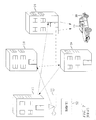
- Multi-paths are caused by reflections and other disturbances between the transmitter and the receiver. Differing paths of reflections cause the receiver to see multiple 'sources' of the same transmitted signal, the multiple 'sources' traveling over different paths. Since the paths are not all of the same length, the multiple reflections or 'sources' of a same transmitted signal may arrive at a receiver at slightly differing times.
- Fig. 7 shows multi-paths in a conventional mobile communications system.
- a transmitter 502 transmits a signal to a mobile receiver 504.
- two paths (1) and (2) are shown.
- Path (1) first reflects off building 510, then off building 514, then off building 512, then off building 516, and finally reaches its destination receiver 504.
- a more direct path (2) reflects off only building 516 before reaching the receiver 504.
- a signal be directly received by the receiver 504 without any reflections.
- the different paths that a portion of the signal takes before being received by the receiver 504 each require a given amount of time to make the trip.
- Multi-path movements are generally tracked by adjustments of tap weights on linear transversal filters ( S. Qureshi, "Adaptive Equalization", Processing of IEEE (1985 )). As the delay of a particular path changes, the magnitude of the tap weight corresponding to the old delay is decreased, while the magnitude of the tap weight corresponding to the new delay is increased.
- the signals taking paths that are positioned outside the filter span are not captured by the linear transversal equalizer. This loss of some portion of the original signal effectively reduces the total signal strength received by the receiver.
- a receiver device including a linear transversal equalizer comprises a filter multiplies each of a plurality of taps by respective ones of a plurality of tap weights to generate a plurality of tap products.
- a filter combinatorial module combines the plurality of tap products into an output of the linear transversal equalizer.
- An alignment multiplier multiplies each of a plurality of function values by respective ones of the plurality of tap weights to generate a plurality of alignment products.
- An alignment combinatorial module combines the plurality of alignment products into an alignment measure signal. A span of the linear transversal equalizer is controlled by the alignment measure signal.
- a method of adjusting a span of a linear transversal equalizer in accordance with another aspect of the present invention comprises multiplying each of a plurality of tap weights of the linear transversal equalizer by a respective one of a plurality of function values to generate a corresponding plurality of alignment products.
- the plurality of alignment products are combined to generate an alignment measure signal.
- the span of the linear transversal equalizer is adjusted based on a value of the alignment measure signal.
- a linear transversal equalizer which covers the temporal spread of a transmitted signal due to multi-paths introduced by the channel.
- the span of the inventive linear transversal equalizer moves according to the current positions of the multi-paths.
- the present invention measures quantitatively how accurately the filter span aligns with the current positions of the multi-paths. Using this alignment measurement, adjustments to the filter span are made to enable the linear transversal filter to capture most of the available energy of the transmitted signal.
- Fig. 1 shows a linear transversal equalizer including an alignment measure module 160 to adjust a span of the linear transversal equalizer 100 based on the value of the alignment measure signal 162, in accordance with the principles of the present invention.
- a linear transversal equalizer 100 includes taps 102, 104, 106, with samples that are multiplied in multipliers 410, 412, 414 by respective tap weights w0, w1, wN.
- the products from each of the multipliers 410, 412, 414 is summed in a summer 150, to generate an output signal from the linear transversal equalizer 100.
- the tap weights w0, w1, wN are input to an alignment measure module 160, where they are monitored and measured.
- Each of the tap weights w0, w1, wN are converted to an absolute value, as depicted by absolute value modules 501, 502, 509, and multiplied by multipliers 510, 512, 514 by values f0, f1, fN of a predefined function f.
- the absolute value function may be performed after multiplication, within the principles of the present invention.
- the modulus of each of the tap weights (w0 to wN) of the linear transversal equalizer are calculated and multiplied with the values of a predefined function (f0 to fN).
- the predefined function f can be stored in an appropriate memory device, storage device, or generated by logic.
- the products output by the multipliers 510, 512 and 514 are summed in a summer module 550, and output as an alignment measure signal align_meas. Then, the magnitude of the sum of products output (align_meas) is used as a quantitative measure of the alignment of the linear transversal equalizer span.
- the sign of the alignment measure signal align_meas can be used to determine the direction of mis-alignment. Or, stated another way, the sign of the alignment measure signal align_meas can be used to control the direction of realignment movement of the span of the linear transversal equalizer 100.
- the alignment measure signal align_meas which is the sum of the product between the function f and the tap weights w0 to wN. This indicates that the largest tap weight is currently in the middle of the span. As a result, most of the available signal energy should be captured by the linear transversal equalizer 100 and thus by the receiver. However, if the delay of the path is smaller, the largest tap weight shifts towards tap 0, and the magnitude of the alignment measure signal align_meas increases. In such a case, the sign of the alignment measure signal align_meas is positive.
- the linear transversal equalizer 100 can be adjusted to span on the earlier received samples. In such case, the alignment of the linear transversal equalizer is adjusted such tha the largest tap weight is moved towards the middle of the span, and the magnitude of the alignment measure signal align_meas decreases. On the other hand, if the delay of the path is larger, the largest tap weight is moved towards tap N, and the magnitude- of the alignment measure signal align_meas increases. In this case, the sign of the alignment measure signal align_meas is negative.
- the span of the linear transversal equalizer 100 can be adjusted to span on the later receiver samples. In such case, the largest tap weight is moved towards the middle of the span, and the magnitude of the alignment measure signal align_meas decreases.
- Fig. 2 shows an exemplary method of generating an alignment measure signal, and adjusting a span of a linear transversal equalizer based on the value of the alignment measure signal, in accordance with the principles of the present invention.
- each tap weight w0 to wN is found, and multiplied by respective values f0 to fN of a pre-defined weighting function f.
- step 294 the weight products w0f0, w1f1, ... wNfN are combined to generate a magnitude of an alignment measure signal.
- the weight products are simply added.
- other combinatorial methods or techniques may be utilized to produce a suitable alignment measure signal.
- step 296 the span of the linear transversal equation 100 (Fig. 1) is adjusted in a direction indicated by the sign of the alignment measure signal.
- step 298 the span of the linear transversal equation 100 (Fig. 1) is adjusted an amount indicated by a magnitude of the alignment measure signal.
- Steps 296 and 298 may be performed in opposite order, or simultaneously, in accordance with the principles of the present invention.
- the steps of Fig. 2 are re-performed preferably at each sample period.
- the steps of Fig. 2 may be performed periodically, e.g., after a fixed number of samples are input, or even based on a fixed time period, according to the principles of the invention.
- Figs. 3 and 4 show some possible functions f that can be used to weight the products calculated by the alignment measure module to control an adjustment placing the largest tap weight to the middle of the span of the linear transversal equalizer, in accordance with the principles of the present invention.
- one exemplary function f is shown which is a straight line function that has negative slope, with a zero crossing at the tap position N/2.
- Fig. 4 shows another exemplary function f which is a curving function with increasing negative slope between tap position 0 and tap position N/2, an infinite slope at the zero crossing at tap position N/2, and with progressively decreasing positive slope between tap position N/2 and tap position N.
- Figs. 3 and 4 show but two preferred functions f out of many possible functions f.
- the magnitudes of tap weights w0, w1, wN of the linear transversal equalizer filter are multiplied by tap position values of the function f.
- the function f has zeroes at desired points for the larger tap weights (e.g., at tap position N/2).
- the gradient of the function f at the zeroes of the function is non-zero.
- function f satisfies the following conditions:
- Fig. 5 shows a possible function f for two multipaths, exhibiting zero crossings at N/4, N/2, and 3N/4.
- the frequency of evaluation of the sum of the product between function f and weights w can be adjusted according to any knowledge on the movement of the receiver. For example, if it is known that the receiver moves very slowly, the evaluation (and thus the adjustment) should be done infrequently to reduce power consumption of the receiver.
- the invention may be implemented in an integrated circuit, and/or in embedded software controlling an integrated circuit.
- the tap weights may each be differentiated, and the respective zeroes may be located and compared with a desired position to produce a suitable alignment measure signal.
- the present invention has advantages. For instance, it is simple to implement, has flexibility of function f so the alignment measurement can adapt to all channel conditions, and allows simple hardware implementation of equalizer span adjustment.
Landscapes
- Engineering & Computer Science (AREA)
- Power Engineering (AREA)
- Computer Networks & Wireless Communication (AREA)
- Signal Processing (AREA)
- Cable Transmission Systems, Equalization Of Radio And Reduction Of Echo (AREA)
- Testing, Inspecting, Measuring Of Stereoscopic Televisions And Televisions (AREA)
Abstract
Description
- This invention relates to linear filters. More particularly, it relates to architecture including a linear transversal equalizer.
- Third Generation (3G) Universal Mobile Telecommunications System (UMTS) designs offer mobile operators significant capacity and broadband capabilities to support great numbers of voice and data customers - especially in urban centers. Making use of radio spectrum in bands identified by the International Telecommunications Union (ITU) and subsequently licensed to operators, 3G/UMTS employs a 5 MHz channel carrier width to deliver significantly higher data rates and increased capacity as compared with second generation networks. This 5 MHz channel carrier provides optimum use of radio resources, especially for operators who have been granted large, contiguous blocks of spectrum - typically ranging from 2x10 MHz up to 2x20 MHz - to reduce the cost of deploying 3G networks.
- 3G/UMTS has been specified as an integrated solution for mobile voice and data with wide area coverage. Universally standardized via the Third Generation Partnership Project (www.3gpp.org) and using globally harmonized spectrum in paired and unpaired bands, 3G/UMTS in its initial phase offers theoretical bit rates of up to 384 kbps in high mobility situations, rising as high as 2 Mbps in stationary/nomadic user environments. Symmetry between uplink and downlink data rates when using paired (FDD) spectrum also means that 3G/UMTS is ideally suited for applications such as real-time video telephony - in contrast with other technologies such as Asynchronous Digital Subscriber Line (ADSL) where there is a pronounced asymmetry between uplink and downlink throughput rates.
- Specified and implemented as an end-to-end mobile system, 3G/UMTS also features the additional benefits of automatic international roaming plus integral security and billing functions, allowing operators to migrate from 2G to 3G while retaining many of their existing back-office systems. Offering increased capacity and speed at lower incremental cost as compared with second generation mobile systems, 3G/UMTS gives operators the flexibility to introduce new multimedia services to business users and consumers while providing an enhanced user experience. This in turn provides the opportunity for operators to build on the brand-based relationships they already enjoy with their customers - and drive new revenue opportunities by encouraging additional traffic, stimulating new usage patterns and strengthening customer loyalty.
- Ongoing technical work within 3GPP will see further increases in throughput speeds of the WCDMA Radio Access Network (RAN). High Speed Downlink Packet Access (HSDPA) and High Speed Uplink Packet Access (HSUPA) technologies are already standardized and are undergoing network trials with operators in the Far East and North America. Promising theoretical downlink speeds as high as 14.4 Mbps (and respectively 5.8 Mbps uplink), these technologies will play an instrumental role in positioning 3G/UMTS as a key enabler for true 'mobile broadband'. Offering data transmission speeds on the same order of magnitude as today's Ethernet-based networks that are a ubiquitous feature of the fixed-line environment, 3G/UMTS will offer enterprise customers and consumers all the benefits of broadband connectivity whilst on the move.
- The linear transversal equalizer (LTE) has been one of the more encouraging technologies for receivers in high-speed data transmission, e.g. high speed downlink packet access (HSDPA) in communications systems conforming to standards promulgated by the Third Generation Partnership Project (3GPP). This is because of the simplicity of a linear transversal equalizer, and its ability to cancel intersymbol interference (ISI).
- A linear transversal equalizer is essentially a linear filter on a delay-line of received complex data. The linear transversal equalizer has multiple taps (i.e., samples), and each filter tap is multiplied by a complex weight.
- Fig. 6 depicts a conventional linear transversal equalizer.
- In particular, as shown in Fig. 6, a conventional linear
transversal equalizer 600 includes multiple taps (i.e. samples) 602, 604, 606, each with a respective tap weight w0, w1, wN.Tap 604 is delayed fromtap 602, andtap 606 is delayed fromtap 604. The signal at eachtap multipliers output 650 having a given signal strength. - One of the difficulties faced by conventional linear transversal equalizers is that the transmitted signal spreads temporally due to multi-paths introduced by the channel as the receiver moves about.
- Multi-paths are caused by reflections and other disturbances between the transmitter and the receiver. Differing paths of reflections cause the receiver to see multiple 'sources' of the same transmitted signal, the multiple 'sources' traveling over different paths. Since the paths are not all of the same length, the multiple reflections or 'sources' of a same transmitted signal may arrive at a receiver at slightly differing times.
- As an example, Fig. 7 shows multi-paths in a conventional mobile communications system. As shown in Fig. 7, a
transmitter 502 transmits a signal to amobile receiver 504. To exemplify the multitude of paths that might be possible in any particular situation, two paths (1) and (2) are shown. - Path (1) first reflects off
building 510, then offbuilding 514, then offbuilding 512, then offbuilding 516, and finally reaches itsdestination receiver 504. A more direct path (2) reflects off onlybuilding 516 before reaching thereceiver 504. Of course, it is also possible that a signal be directly received by thereceiver 504 without any reflections. Needless to say, the different paths that a portion of the signal takes before being received by thereceiver 504 each require a given amount of time to make the trip. - Multi-path movements are generally tracked by adjustments of tap weights on linear transversal filters (S. Qureshi, "Adaptive Equalization", Processing of IEEE (1985)). As the delay of a particular path changes, the magnitude of the tap weight corresponding to the old delay is decreased, while the magnitude of the tap weight corresponding to the new delay is increased.
- As the delay spread of the multi-paths moves beyond the span of the particular linear transversal filter, the signals taking paths that are positioned outside the filter span are not captured by the linear transversal equalizer. This loss of some portion of the original signal effectively reduces the total signal strength received by the receiver.
- There is a need for reduced signal loss due to dropped multi-path signals, so that overall signal strength of a received signal through a linear transversal equalizer is increased.
- In accordance with the principles of the present invention, a receiver device including a linear transversal equalizer comprises a filter multiplies each of a plurality of taps by respective ones of a plurality of tap weights to generate a plurality of tap products. A filter combinatorial module combines the plurality of tap products into an output of the linear transversal equalizer. An alignment multiplier multiplies each of a plurality of function values by respective ones of the plurality of tap weights to generate a plurality of alignment products. An alignment combinatorial module combines the plurality of alignment products into an alignment measure signal. A span of the linear transversal equalizer is controlled by the alignment measure signal.
- A method of adjusting a span of a linear transversal equalizer in accordance with another aspect of the present invention comprises multiplying each of a plurality of tap weights of the linear transversal equalizer by a respective one of a plurality of function values to generate a corresponding plurality of alignment products. The plurality of alignment products are combined to generate an alignment measure signal. The span of the linear transversal equalizer is adjusted based on a value of the alignment measure signal.
- Features and advantages of the present invention will become apparent to those skilled in the art from the following description with reference to the drawings, in which:
- Fig. 1 shows a linear transversal equalizer including an alignment measure module to adjust a span of the linear transversal equalizer based on the value of the alignment measure signal, in accordance with the principles of the present invention.
- Fig. 2 shows an exemplary method of generating an alignment measure signal, and adjusting a span of a linear transversal equalizer based on the value of the alignment measure signal, in accordance with the principles of the present invention.
- Figs. 3 and 4 show some possible functions f that can be used to weight the products calculated by the alignment measure module to control an adjustment placing the largest tap weight to the middle of the span of the linear transversal equalizer, in accordance with the principles of the present invention.
- Fig. 5 shows a possible function f for two multipaths, exhibiting zero crossings at N/4, N/2, and 3N/4.
- Fig. 6 depicts a conventional linear transversal equalizer.
- Fig. 7 shows multi-paths in a conventional mobile communications system.
- In accordance with the principles of the present invention, a linear transversal equalizer is provided which covers the temporal spread of a transmitted signal due to multi-paths introduced by the channel. As the receiver moves in space with respect to the signal source, the span of the inventive linear transversal equalizer moves according to the current positions of the multi-paths. In particular, the present invention measures quantitatively how accurately the filter span aligns with the current positions of the multi-paths. Using this alignment measurement, adjustments to the filter span are made to enable the linear transversal filter to capture most of the available energy of the transmitted signal.
- Fig. 1 shows a linear transversal equalizer including an
alignment measure module 160 to adjust a span of the lineartransversal equalizer 100 based on the value of the alignment measure signal 162, in accordance with the principles of the present invention. - In particular, as shown in Fig. 1, a linear
transversal equalizer 100 includestaps multipliers multipliers summer 150, to generate an output signal from the lineartransversal equalizer 100. - In accordance with the principles of the present invention, the tap weights w0, w1, wN are input to an
alignment measure module 160, where they are monitored and measured. - Each of the tap weights w0, w1, wN are converted to an absolute value, as depicted by
absolute value modules multipliers - The products output by the
multipliers - Preferably, the sign of the alignment measure signal align_meas can be used to determine the direction of mis-alignment. Or, stated another way, the sign of the alignment measure signal align_meas can be used to control the direction of realignment movement of the span of the linear
transversal equalizer 100. - In particular, if the largest tap weight is in the middle of the span, the alignment measure signal align_meas, which is the sum of the product between the function f and the tap weights w0 to wN, is small. This indicates that the largest tap weight is currently in the middle of the span. As a result, most of the available signal energy should be captured by the linear
transversal equalizer 100 and thus by the receiver. However, if the delay of the path is smaller, the largest tap weight shifts towardstap 0, and the magnitude of the alignment measure signal align_meas increases. In such a case, the sign of the alignment measure signal align_meas is positive. - If the magnitude of the alignment measure signal align_meas is larger than a specified threshold, then the linear
transversal equalizer 100 can be adjusted to span on the earlier received samples. In such case, the alignment of the linear transversal equalizer is adjusted such tha the largest tap weight is moved towards the middle of the span, and the magnitude of the alignment measure signal align_meas decreases. On the other hand, if the delay of the path is larger, the largest tap weight is moved towards tap N, and the magnitude- of the alignment measure signal align_meas increases. In this case, the sign of the alignment measure signal align_meas is negative. - If the magnitude of the alignment measure signal align_meas is larger than a specified threshold, then the span of the linear
transversal equalizer 100 can be adjusted to span on the later receiver samples. In such case, the largest tap weight is moved towards the middle of the span, and the magnitude of the alignment measure signal align_meas decreases. - Fig. 2 shows an exemplary method of generating an alignment measure signal, and adjusting a span of a linear transversal equalizer based on the value of the alignment measure signal, in accordance with the principles of the present invention.
- In particular, as shown in
step 292 of Fig. 2, the magnitude of each tap weight w0 to wN is found, and multiplied by respective values f0 to fN of a pre-defined weighting function f. - In
step 294, the weight products w0f0, w1f1, ... wNfN are combined to generate a magnitude of an alignment measure signal. In the disclosed embodiments, the weight products are simply added. However, other combinatorial methods or techniques may be utilized to produce a suitable alignment measure signal. - In
step 296, the span of the linear transversal equation 100 (Fig. 1) is adjusted in a direction indicated by the sign of the alignment measure signal. - In
step 298, the span of the linear transversal equation 100 (Fig. 1) is adjusted an amount indicated by a magnitude of the alignment measure signal. -
Steps - The steps of Fig. 2 are re-performed preferably at each sample period. Alternatively, the steps of Fig. 2 may be performed periodically, e.g., after a fixed number of samples are input, or even based on a fixed time period, according to the principles of the invention.
- Figs. 3 and 4 show some possible functions f that can be used to weight the products calculated by the alignment measure module to control an adjustment placing the largest tap weight to the middle of the span of the linear transversal equalizer, in accordance with the principles of the present invention.
- In particular, as shown in Fig. 3, one exemplary function f is shown which is a straight line function that has negative slope, with a zero crossing at the tap position N/2.
- Fig. 4 shows another exemplary function f which is a curving function with increasing negative slope between
tap position 0 and tap position N/2, an infinite slope at the zero crossing at tap position N/2, and with progressively decreasing positive slope between tap position N/2 and tap position N. - Figs. 3 and 4 show but two preferred functions f out of many possible functions f. For all pre-defined functions f, the magnitudes of tap weights w0, w1, wN of the linear transversal equalizer filter are multiplied by tap position values of the function f. Preferably, the function f has zeroes at desired points for the larger tap weights (e.g., at tap position N/2). Also, preferably, the gradient of the function f at the zeroes of the function (i.e., where the function value crosses from positive to negative) is non-zero.
- Thus, while there are many possibilities for function f which can provide good alignment measurements for different channel conditions, it is preferred that the function f satisfy the following conditions:
- 1. That the zeroes of the function f be on taps where the larger tap weights are desired to be adjusted to be; and
- 2. That the gradients of the function f at all zeroes of the function f are either all positive or all negative. For example, if there are two major paths in the channel, and their corresponding taps are N/2 apart.
- Fig. 5 shows a possible function f for two multipaths, exhibiting zero crossings at N/4, N/2, and 3N/4.
- In particular, as shown in Fig. 5, the frequency of evaluation of the sum of the product between function f and weights w can be adjusted according to any knowledge on the movement of the receiver. For example, if it is known that the receiver moves very slowly, the evaluation (and thus the adjustment) should be done infrequently to reduce power consumption of the receiver.
- The invention may be implemented in an integrated circuit, and/or in embedded software controlling an integrated circuit.
- While the present embodiments are described wherein tap weights are multiplied by a function, and a combination of the products results in an alignment measure signal. However, the principles of the present invention relate to any linear transform on the tap weights. For example, the tap weights may each be differentiated, and the respective zeroes may be located and compared with a desired position to produce a suitable alignment measure signal.
- The present invention has advantages. For instance, it is simple to implement, has flexibility of function f so the alignment measurement can adapt to all channel conditions, and allows simple hardware implementation of equalizer span adjustment.
- While the invention has been described with reference to the exemplary embodiments thereof, those skilled in the art will be able to make various modifications to the described embodiments of the invention without departing from the true spirit and scope of the invention.
Claims (28)
- In a receiver device, a linear transversal equalizer comprising:a plurality of taps;a plurality of tap weights;a first operator to transform each of said plurality of taps by respective ones of said plurality of tap weights to generate a plurality of tap products; anda filter combinatorial module to combine said plurality of tap products into an output of said linear transversal equalizer;a plurality of function values;an alignment multiplier to multiply each of said plurality of function values by respective ones of said plurality of tap weights to generate a plurality of alignment products; andan alignment combinatorial module to combine said plurality of alignment products into an alignment measure signal;wherein a span of said linear transversal equalizer is controlled by said alignment measure signal.
- In said receiver device including said linear transversal equalizer according to claim 1, wherein:said first operator transforms each of said plurality of taps by multiplying each by said respective ones of said plurality of tap weights to generate said plurality of tap products.
- In said receiver device including said linear transversal equalizer according to claim 1, wherein:said plurality of function values form a linear function going from a first tap toward a last tap;wherein one zero of said function is located at a center of said span of said linear transversal equalizer; andany gradients of said function at any zero of said function are either all positive or all negative.
- In said receiver device including said linear transversal equalizer according to claim 1, wherein:said alignment combinatorial module adds each of said plurality of alignment products.
- In said receiver device including said linear transversal equalizer according to claim 1, wherein:a direction of adjustment to said span of said linear transversal equalizer is determined based on a sign of said alignment measure signal.
- In said receiver device including said linear transversal equalizer according to claim 1, wherein:a magnitude of adjustment to said span of said linear transversal equalizer is determined based on a combination of an absolute value of said plurality of alignment products.
- In said receiver device including said linear transversal equalizer according to claim 1, further comprising:an absolute value module, to convert a value of each of said tap weights into a magnitude.
- In said receiver device including said linear transversal equalizer according to claim 1, further comprising:a low pass filter module, to filter said plurality of tap weights into a plurality of filtered tap weights.
- In said receiver device including said linear transversal equalizer according to claim 1, wherein:said plurality of function values form a linear function going from a first tap toward a last tap;wherein said function has zeroes at desired points for larger ones of said plurality of tap weights, and a non-zero gradient at its zeroes.
- A method of adjusting a span of a linear transversal equalizer, comprising:transforming each of a plurality of tap weights of said linear transversal equalizer by a respective one of a plurality of function values to generate a corresponding plurality of alignment products;combining said plurality of alignment products to generate an alignment measure signal; andadjusting said span of said linear transversal equalizer based on a value of said alignment measure signal.
- The method of adjusting a span of a linear transversal equalizer according to claim 9, wherein said transforming comprises:filtering said plurality of tap weights by a low pass filter to form a plurality of filtered tap weights;calculating the magnitudes of said plurality of filtered tap weights; andmultiplying each of said plurality of magnitudes by respective ones of said plurality of function values to generate said plurality of alignment products.
- The method of adjusting a span of a linear transversal equalizer according to claim 11, wherein:said plurality of function values form a linear function going from a first tap toward a last tap;wherein one zero of said function is located at a center of said span of said linear transversal; andany gradients of said function at any zero of said function are either all positive or all negative.
- The method of adjusting a span of a linear transversal equalizer according to claim 11, wherein said combining comprises:adding each of said plurality of alignment products.
- The method of adjusting a span of a linear transversal equalizer according to claim 11, wherein said adjusting comprises:adjusting said span in a direction determined based on a sign of said alignment measure signal.
- The method of adjusting a span of a linear transversal equalizer according to claim 11, wherein said adjusting comprises:adjusting said span an amount determined based on a combination of an absolute value of said plurality of alignment products.
- The method of adjusting a span of a linear transversal equalizer according to claim 11, further comprising:converting a value of each of said tap weights into a magnitude value.
- The method of adjusting a span of a linear transversal equalizer according to claim 11, further comprising:filtering a value of each of said tap weights by a low pass filter.
- The method of adjusting a span of a linear transversal equalizer according to claim 11, wherein:said plurality of function values form a linear function going from a first tap toward a last tap;wherein said function has zeroes at desired points for larger ones of said plurality of tap weights, and a non-zero gradient at its zeroes.
- Apparatus for adjusting a span of a linear transversal equalizer, comprising:means for performing linear transform on a plurality of tap weights of said linear transversal equalizer to generate an alignment measure signal; andmeans for adjusting said span of said linear transversal equalizer based on a value of said alignment measure signal.
- The apparatus for adjusting a span of a linear transversal equalizer according to claim 19, wherein said means for performing linear transform comprises:means for multiplying each of said plurality of taps by respective ones of a plurality of function values to generate a plurality of alignment products; andmeans for combining said plurality of alignment products into an alignment measure signal.
- The apparatus for adjusting a span of a linear transversal equalizer according to claim 20, wherein:said plurality of function values form a linear function going from a first tap toward a last tap;wherein one zero of said function is located at a center of said span of said linear transversal equalizer; andany gradients of said function at any zero of said function are either all positive or all negative.
- The apparatus for adjusting a span of a linear transversal equalizer according to claim 20, wherein said means for combining comprises:means for adding each of said plurality of alignment products.
- The apparatus for adjusting a span of a linear transversal equalizer according to claim 20, wherein said means for adjusting comprises:means for adjusting said span in a direction determined based on a sign of said alignment measure signal.
- The apparatus for adjusting a span of a linear transversal equalizer according to claim 20, wherein said means for adjusting comprises:means for adjusting said span an amount determined based on a combination of an absolute value of said plurality of alignment products.
- The apparatus for adjusting a span of a linear transversal equalizer according to claim 20, further comprising:means for converting a value of each of said tap weights into a magnitude value.
- The apparatus for adjusting a span of a linear transversal equalizer according to claim 20, further comprising:means for fiiltering a value of each of said tap weights by a low pass filter.
- The apparatus for adjusting a span of a linear transversal equalizer according to claim 20, wherein:said plurality of function values form a linear function going from a first tap toward a last tap;wherein said function has zeroes at desired points for larger ones of said plurality of tap weights, and a non-zero gradient at its zeroes.
- The apparatus for adjusting a span of a linear transversal equalizer according to claim 19, wherein said means for performing linear transform comprises:means for forming a linear function based on said plurality of taps weights;means for differentiating said linear function to form a derivative of said linear function;means for locating zeroes in said derivative of said linear function;means for calculating a plurality of distances between said zeroes and the desired point for largest tap; andmeans for combining said plurality of distances into an alignment measure signal.
Priority Applications (1)
| Application Number | Priority Date | Filing Date | Title |
|---|---|---|---|
| EP10181442.4A EP2259518B1 (en) | 2005-04-26 | 2006-03-30 | Measurement of equalizer span alignment with respect to channel condition |
Applications Claiming Priority (1)
| Application Number | Priority Date | Filing Date | Title |
|---|---|---|---|
| US11/114,025 US7577697B2 (en) | 2005-04-26 | 2005-04-26 | Measurement of equalizer span alignment with respect to channel condition |
Related Child Applications (2)
| Application Number | Title | Priority Date | Filing Date |
|---|---|---|---|
| EP10181442.4A Division EP2259518B1 (en) | 2005-04-26 | 2006-03-30 | Measurement of equalizer span alignment with respect to channel condition |
| EP10181442.4A Division-Into EP2259518B1 (en) | 2005-04-26 | 2006-03-30 | Measurement of equalizer span alignment with respect to channel condition |
Publications (4)
| Publication Number | Publication Date |
|---|---|
| EP1718020A2 true EP1718020A2 (en) | 2006-11-02 |
| EP1718020A3 EP1718020A3 (en) | 2007-10-03 |
| EP1718020B1 EP1718020B1 (en) | 2016-02-03 |
| EP1718020B8 EP1718020B8 (en) | 2016-03-16 |
Family
ID=36992537
Family Applications (2)
| Application Number | Title | Priority Date | Filing Date |
|---|---|---|---|
| EP10181442.4A Ceased EP2259518B1 (en) | 2005-04-26 | 2006-03-30 | Measurement of equalizer span alignment with respect to channel condition |
| EP06251787.5A Ceased EP1718020B8 (en) | 2005-04-26 | 2006-03-30 | Measurement of equalizer span alignment with respect to channel condition |
Family Applications Before (1)
| Application Number | Title | Priority Date | Filing Date |
|---|---|---|---|
| EP10181442.4A Ceased EP2259518B1 (en) | 2005-04-26 | 2006-03-30 | Measurement of equalizer span alignment with respect to channel condition |
Country Status (2)
| Country | Link |
|---|---|
| US (1) | US7577697B2 (en) |
| EP (2) | EP2259518B1 (en) |
Citations (1)
| Publication number | Priority date | Publication date | Assignee | Title |
|---|---|---|---|---|
| WO2001020780A1 (en) | 1999-09-13 | 2001-03-22 | Virata Corporation | xDSL MODEM HAVING TIME DOMAIN FILTER FOR ISI MITIGATION |
Family Cites Families (3)
| Publication number | Priority date | Publication date | Assignee | Title |
|---|---|---|---|---|
| US6414990B1 (en) * | 1998-09-29 | 2002-07-02 | Conexant Systems, Inc. | Timing recovery for a high speed digital data communication system based on adaptive equalizer impulse response characteristics |
| US7266145B2 (en) * | 2002-11-08 | 2007-09-04 | Scintera Networks, Inc. | Adaptive signal equalizer with adaptive error timing and precursor/postcursor configuration control |
| US20040091036A1 (en) * | 2002-11-08 | 2004-05-13 | Venugopal Balasubramonian | Adaptive signal equalizer with adaptive error timing and precursor/postcursor configuration control |
-
2005
- 2005-04-26 US US11/114,025 patent/US7577697B2/en not_active Expired - Fee Related
-
2006
- 2006-03-30 EP EP10181442.4A patent/EP2259518B1/en not_active Ceased
- 2006-03-30 EP EP06251787.5A patent/EP1718020B8/en not_active Ceased
Patent Citations (1)
| Publication number | Priority date | Publication date | Assignee | Title |
|---|---|---|---|---|
| WO2001020780A1 (en) | 1999-09-13 | 2001-03-22 | Virata Corporation | xDSL MODEM HAVING TIME DOMAIN FILTER FOR ISI MITIGATION |
Also Published As
| Publication number | Publication date |
|---|---|
| EP2259518B1 (en) | 2015-07-22 |
| EP1718020B1 (en) | 2016-02-03 |
| EP1718020B8 (en) | 2016-03-16 |
| EP1718020A3 (en) | 2007-10-03 |
| US7577697B2 (en) | 2009-08-18 |
| EP2259518A1 (en) | 2010-12-08 |
| US20060239340A1 (en) | 2006-10-26 |
Similar Documents
| Publication | Publication Date | Title |
|---|---|---|
| EP1599951B1 (en) | Transmit diversity and separating multiple loopback signals | |
| CN101814931B (en) | Doppler frequency shift estimation and compensation method in TD-SCDMA (Time Division-Synchronization Code Division Multiple Access) system | |
| AU2004213989B2 (en) | Communication receiver with an adaptive equalizer | |
| JP2011176836A (en) | Communication receiver with adaptive equalizer that uses channel estimation | |
| CN101361334A (en) | Method and apparatus for filtering noisy estimates to reduce estimation error | |
| MXPA02002701A (en) | System and method for accurately predicting signal to interference and noise ratio to improve communications system performance. | |
| WO2000048332A1 (en) | Approximated mmse-based channel estimator in a mobile communication system | |
| JP4847313B2 (en) | Equalization of received multiple signals for soft handoff in wireless communication systems | |
| KR101506747B1 (en) | Method and apparatus for efficient signal interpolation | |
| JP4494012B2 (en) | Method and apparatus for adjusting delay in a system with a time burst pilot and fractional interval equalizer | |
| US20050249274A1 (en) | Linear filter equalizer | |
| JP2006352807A (en) | Communication apparatus and communication method | |
| JP2004501568A (en) | Method and apparatus for estimating channel adapted to speed | |
| US7577194B2 (en) | Equalizer and equalization method | |
| US7181185B2 (en) | Apparatus and method for performing channel estimations using non-linear filter | |
| EP1718020B1 (en) | Measurement of equalizer span alignment with respect to channel condition | |
| CN101480004B (en) | A method for controlling channel estimation search window, its program and receiving device | |
| JP3718403B2 (en) | Rake receiver | |
| Caso et al. | Performance evaluation of non-prefiltering vs. time reversal prefiltering in distributed and uncoordinated IR-UWB ad-hoc networks | |
| US9479360B2 (en) | Receiver apparatus and reception method in wireless communication system | |
| US7466779B2 (en) | Data transmission method, data transmission arrangement and base station | |
| Ozen | A novel variable step size adjustment method based on channel output autocorrelation for the LMS training algorithm | |
| Hassan | A novel structure of high speed OFDM receiver to overcome ISI and ICI in Rayleigh fading channel | |
| KR102166404B1 (en) | Apparatus and method for receving signal in wireless communication | |
| CN101129007B (en) | Channel estimation method for TDD-CDMA system |
Legal Events
| Date | Code | Title | Description |
|---|---|---|---|
| PUAI | Public reference made under article 153(3) epc to a published international application that has entered the european phase |
Free format text: ORIGINAL CODE: 0009012 |
|
| AK | Designated contracting states |
Kind code of ref document: A2 Designated state(s): AT BE BG CH CY CZ DE DK EE ES FI FR GB GR HU IE IS IT LI LT LU LV MC NL PL PT RO SE SI SK TR |
|
| AX | Request for extension of the european patent |
Extension state: AL BA HR MK YU |
|
| PUAL | Search report despatched |
Free format text: ORIGINAL CODE: 0009013 |
|
| AK | Designated contracting states |
Kind code of ref document: A3 Designated state(s): AT BE BG CH CY CZ DE DK EE ES FI FR GB GR HU IE IS IT LI LT LU LV MC NL PL PT RO SE SI SK TR |
|
| AX | Request for extension of the european patent |
Extension state: AL BA HR MK YU |
|
| RIC1 | Information provided on ipc code assigned before grant |
Ipc: H04L 7/02 20060101ALI20070828BHEP Ipc: H04L 25/03 20060101AFI20060927BHEP |
|
| 17P | Request for examination filed |
Effective date: 20080218 |
|
| 17Q | First examination report despatched |
Effective date: 20080320 |
|
| AKX | Designation fees paid |
Designated state(s): DE GB |
|
| GRAP | Despatch of communication of intention to grant a patent |
Free format text: ORIGINAL CODE: EPIDOSNIGR1 |
|
| INTG | Intention to grant announced |
Effective date: 20150828 |
|
| GRAS | Grant fee paid |
Free format text: ORIGINAL CODE: EPIDOSNIGR3 |
|
| GRAA | (expected) grant |
Free format text: ORIGINAL CODE: 0009210 |
|
| AK | Designated contracting states |
Kind code of ref document: B1 Designated state(s): DE GB |
|
| REG | Reference to a national code |
Ref country code: GB Ref legal event code: FG4D |
|
| GRAT | Correction requested after decision to grant or after decision to maintain patent in amended form |
Free format text: ORIGINAL CODE: EPIDOSNCDEC |
|
| REG | Reference to a national code |
Ref country code: DE Ref legal event code: R081 Ref document number: 602006047869 Country of ref document: DE Owner name: AVAGO TECHNOLOGIES INTERNATIONAL SALES PTE. LT, SG Free format text: FORMER OWNER: AGERE SYSTEMS, INC., ALLENTOWN, PA., US |
|
| RAP2 | Party data changed (patent owner data changed or rights of a patent transferred) |
Owner name: AVAGO TECHNOLOGIES GENERAL IP (SINGAPORE) PTE. LTD |
|
| REG | Reference to a national code |
Ref country code: DE Ref legal event code: R096 Ref document number: 602006047869 Country of ref document: DE |
|
| REG | Reference to a national code |
Ref country code: DE Ref legal event code: R081 Ref document number: 602006047869 Country of ref document: DE Owner name: AVAGO TECHNOLOGIES INTERNATIONAL SALES PTE. LT, SG Free format text: FORMER OWNER: AGERE SYSTEMS, INC., ALLENTOWN, PA., US Ref country code: DE Ref legal event code: R082 Ref document number: 602006047869 Country of ref document: DE Representative=s name: DILG, HAEUSLER, SCHINDELMANN PATENTANWALTSGESE, DE Ref country code: DE Ref legal event code: R082 Ref document number: 602006047869 Country of ref document: DE Representative=s name: DILG HAEUSLER SCHINDELMANN PATENTANWALTSGESELL, DE |
|
| REG | Reference to a national code |
Ref country code: DE Ref legal event code: R097 Ref document number: 602006047869 Country of ref document: DE |
|
| PLBE | No opposition filed within time limit |
Free format text: ORIGINAL CODE: 0009261 |
|
| STAA | Information on the status of an ep patent application or granted ep patent |
Free format text: STATUS: NO OPPOSITION FILED WITHIN TIME LIMIT |
|
| 26N | No opposition filed |
Effective date: 20161104 |
|
| GBPC | Gb: european patent ceased through non-payment of renewal fee |
Effective date: 20160503 |
|
| PG25 | Lapsed in a contracting state [announced via postgrant information from national office to epo] |
Ref country code: GB Free format text: LAPSE BECAUSE OF NON-PAYMENT OF DUE FEES Effective date: 20160503 |
|
| REG | Reference to a national code |
Ref country code: DE Ref legal event code: R081 Ref document number: 602006047869 Country of ref document: DE Owner name: AVAGO TECHNOLOGIES INTERNATIONAL SALES PTE. LT, SG Free format text: FORMER OWNER: AVAGO TECHNOLOGIES GENERAL IP (SINGAPORE) PTE. LTD., SINGAPORE, SG Ref country code: DE Ref legal event code: R082 Ref document number: 602006047869 Country of ref document: DE Representative=s name: DILG, HAEUSLER, SCHINDELMANN PATENTANWALTSGESE, DE Ref country code: DE Ref legal event code: R082 Ref document number: 602006047869 Country of ref document: DE Representative=s name: DILG HAEUSLER SCHINDELMANN PATENTANWALTSGESELL, DE |
|
| PGFP | Annual fee paid to national office [announced via postgrant information from national office to epo] |
Ref country code: DE Payment date: 20240311 Year of fee payment: 19 |
|
| REG | Reference to a national code |
Ref country code: DE Ref legal event code: R119 Ref document number: 602006047869 Country of ref document: DE |
|
| PG25 | Lapsed in a contracting state [announced via postgrant information from national office to epo] |
Ref country code: DE Free format text: LAPSE BECAUSE OF NON-PAYMENT OF DUE FEES Effective date: 20251001 |