EP1717926A2 - Battery charger - Google Patents
Battery charger Download PDFInfo
- Publication number
- EP1717926A2 EP1717926A2 EP06112997A EP06112997A EP1717926A2 EP 1717926 A2 EP1717926 A2 EP 1717926A2 EP 06112997 A EP06112997 A EP 06112997A EP 06112997 A EP06112997 A EP 06112997A EP 1717926 A2 EP1717926 A2 EP 1717926A2
- Authority
- EP
- European Patent Office
- Prior art keywords
- battery
- charger
- power
- battery pack
- power sources
- Prior art date
- Legal status (The legal status is an assumption and is not a legal conclusion. Google has not performed a legal analysis and makes no representation as to the accuracy of the status listed.)
- Withdrawn
Links
Images

Classifications
-
- H—ELECTRICITY
- H02—GENERATION; CONVERSION OR DISTRIBUTION OF ELECTRIC POWER
- H02M—APPARATUS FOR CONVERSION BETWEEN AC AND AC, BETWEEN AC AND DC, OR BETWEEN DC AND DC, AND FOR USE WITH MAINS OR SIMILAR POWER SUPPLY SYSTEMS; CONVERSION OF DC OR AC INPUT POWER INTO SURGE OUTPUT POWER; CONTROL OR REGULATION THEREOF
- H02M3/00—Conversion of DC power input into DC power output
- H02M3/02—Conversion of DC power input into DC power output without intermediate conversion into AC
- H02M3/04—Conversion of DC power input into DC power output without intermediate conversion into AC by static converters
- H02M3/10—Conversion of DC power input into DC power output without intermediate conversion into AC by static converters using discharge tubes with control electrode or semiconductor devices with control electrode
- H02M3/145—Conversion of DC power input into DC power output without intermediate conversion into AC by static converters using discharge tubes with control electrode or semiconductor devices with control electrode using devices of a triode or transistor type requiring continuous application of a control signal
- H02M3/155—Conversion of DC power input into DC power output without intermediate conversion into AC by static converters using discharge tubes with control electrode or semiconductor devices with control electrode using devices of a triode or transistor type requiring continuous application of a control signal using semiconductor devices only
- H02M3/156—Conversion of DC power input into DC power output without intermediate conversion into AC by static converters using discharge tubes with control electrode or semiconductor devices with control electrode using devices of a triode or transistor type requiring continuous application of a control signal using semiconductor devices only with automatic control of output voltage or current, e.g. switching regulators
- H02M3/158—Conversion of DC power input into DC power output without intermediate conversion into AC by static converters using discharge tubes with control electrode or semiconductor devices with control electrode using devices of a triode or transistor type requiring continuous application of a control signal using semiconductor devices only with automatic control of output voltage or current, e.g. switching regulators including plural semiconductor devices as final control devices for a single load
- H02M3/1584—Conversion of DC power input into DC power output without intermediate conversion into AC by static converters using discharge tubes with control electrode or semiconductor devices with control electrode using devices of a triode or transistor type requiring continuous application of a control signal using semiconductor devices only with automatic control of output voltage or current, e.g. switching regulators including plural semiconductor devices as final control devices for a single load with a plurality of power processing stages connected in parallel
-
- H—ELECTRICITY
- H02—GENERATION; CONVERSION OR DISTRIBUTION OF ELECTRIC POWER
- H02J—ELECTRIC POWER NETWORKS; CIRCUIT ARRANGEMENTS OR SYSTEMS FOR SUPPLYING OR DISTRIBUTING ELECTRIC POWER; SYSTEMS FOR STORING ELECTRIC ENERGY
- H02J7/00—Circuit arrangements for charging or discharging batteries or for supplying loads from batteries
- H02J7/02—Circuit arrangements for charging or discharging batteries or for supplying loads from batteries for charging batteries from AC mains by converters
-
- H—ELECTRICITY
- H02—GENERATION; CONVERSION OR DISTRIBUTION OF ELECTRIC POWER
- H02J—ELECTRIC POWER NETWORKS; CIRCUIT ARRANGEMENTS OR SYSTEMS FOR SUPPLYING OR DISTRIBUTING ELECTRIC POWER; SYSTEMS FOR STORING ELECTRIC ENERGY
- H02J7/00—Circuit arrangements for charging or discharging batteries or for supplying loads from batteries
- H02J7/90—Regulation of charging or discharging current or voltage
- H02J7/96—Regulation of charging or discharging current or voltage in response to battery voltage
-
- H—ELECTRICITY
- H02—GENERATION; CONVERSION OR DISTRIBUTION OF ELECTRIC POWER
- H02J—ELECTRIC POWER NETWORKS; CIRCUIT ARRANGEMENTS OR SYSTEMS FOR SUPPLYING OR DISTRIBUTING ELECTRIC POWER; SYSTEMS FOR STORING ELECTRIC ENERGY
- H02J7/00—Circuit arrangements for charging or discharging batteries or for supplying loads from batteries
- H02J7/90—Regulation of charging or discharging current or voltage
- H02J7/971—Regulation of charging or discharging current or voltage the charge cycle being controlled or terminated in response to non-electric parameters
- H02J7/975—Regulation of charging or discharging current or voltage the charge cycle being controlled or terminated in response to non-electric parameters in response to temperature
- H02J7/977—Regulation of charging or discharging current or voltage the charge cycle being controlled or terminated in response to non-electric parameters in response to temperature of the battery
-
- H—ELECTRICITY
- H02—GENERATION; CONVERSION OR DISTRIBUTION OF ELECTRIC POWER
- H02J—ELECTRIC POWER NETWORKS; CIRCUIT ARRANGEMENTS OR SYSTEMS FOR SUPPLYING OR DISTRIBUTING ELECTRIC POWER; SYSTEMS FOR STORING ELECTRIC ENERGY
- H02J2207/00—Details of circuit arrangements for charging or discharging batteries or supplying loads from batteries
- H02J2207/20—Charging or discharging characterised by the power electronics converter
-
- H—ELECTRICITY
- H02—GENERATION; CONVERSION OR DISTRIBUTION OF ELECTRIC POWER
- H02J—ELECTRIC POWER NETWORKS; CIRCUIT ARRANGEMENTS OR SYSTEMS FOR SUPPLYING OR DISTRIBUTING ELECTRIC POWER; SYSTEMS FOR STORING ELECTRIC ENERGY
- H02J2207/00—Details of circuit arrangements for charging or discharging batteries or supplying loads from batteries
- H02J2207/40—Details of circuit arrangements for charging or discharging batteries or supplying loads from batteries adapted for charging from various sources, e.g. AC, DC or multivoltage
Definitions
- This invention relates generally to battery chargers and more particularly to battery chargers with multiple current sources.
- the battery packs for portable power tools, outdoor tools and certain kitchen and domestic appliances may include rechargeable batteries, such as lithium, nickel cadmium, nickel metal hydride and lead-acid batteries, so that they can be recharged rather than be replaced. Thereby a substantial cost saving is achieved.
- rechargeable batteries such as lithium, nickel cadmium, nickel metal hydride and lead-acid batteries
- the charger includes a power supply connectable to an outside power source, first and second battery power sources connected to the power supply for providing power to a battery pack, and a controller connected to the first and second battery power sources for controlling the first and second battery power sources.
- the first and second battery power sources are preferably connected in parallel to the battery.
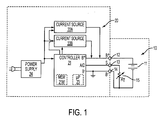
- FIG. 1 A first embodiment of a battery pack and charger according to the invention is shown in FIG. 1.
- a battery pack 10 is connected to a charger 20.
- Battery pack 10 may comprise a plurality of battery cells 11 connected in series and/or parallel, which dictate the voltage and storage capacity for battery pack 10.
- Battery pack 10 may include three battery contacts: first battery contact 12, second battery contact 13, and third battery contact 14.
- Battery contact 12 is the B+ (positive) terminal for battery pack 10.
- Battery contact 14 is the B- or negative/common terminal.
- Battery contact 13 is the S or sensing terminal.
- Battery contacts 12 and 14 receive the charging current sent from the charger 20 (preferably from current source 22, as discussed below) for charging the battery pack 10.
- the battery cells 11 are connected between the battery contacts 12 and 14.
- a temperature sensing device 15 such as a negative temperature coefficient (NTC) resistor, or thermistor, R T .
- NTC negative temperature coefficient
- the temperature sensing device is preferably in closer proximity to the cells 11 for monitoring of the battery temperature.
- other components such as capacitors, etc., or circuits can be used to provide a signal representative of the battery temperature.
- Battery pack 10 may also comprise an identifier as known in the prior art, so that charger 20 can identify the type and capacity of the battery pack, and charge accordingly.
- the charger 20 preferably comprises a controller 21, which in turn includes positive terminal (B+) 16 and negative (B-) terminal 17, which are coupled to battery pack 10 via battery contacts 12 and 14, respectively.
- the positive terminal may also act as an input, preferably an analog/digital input, in order for the controller 21 to detect the battery pack voltage.
- controller 21 may include another input TC, preferably an analog/digital input, which is coupled to the temperature sensing device 15 via the third battery contact 13 (S). This allows the controller 21 to monitor the battery temperature.
- Controller 21 may include a microprocessor 23 for controlling the charging and monitoring operations. Controller may also include a memory 21 M for storing charging instructions for the microprocessor 23 to carry out and/or storing information concerning the charging process, etc.
- Controller 21 may control at least two charging power sources for providing power to the battery pack 10. As shown in FIG. 1, two current sources 22A, 22B provide current to battery pack 10. Current sources 22A, 22B may be integrated within controller 21. Preferably, current sources 22A, 22B are self-oscillating converter circuits.
- Power supply 24 may convert the power received from the vehicle battery, the generator, or the AC outlet to the necessary power requirements of the different elements, as is well known in the art.
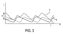
- FIG. 3 illustrates the output currents I A , I B of current sources 22A, 22B, respectively.
- the current I T sent to battery pack 10 will be an addition of output currents I A , I B .
- Persons skilled in the art will recognize that such arrangement provides a charger with higher output current capability at a low cost. Such higher output current allows for faster charging of a battery pack.
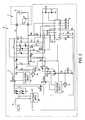
- FIG. 2 illustrates a second embodiment of the battery charger according to the invention.
- the teachings of the previous embodiment are wholly incorporated herein by reference.
- the main difference between the first and the second embodiments is that the second embodiment does not have a connection to the temperature sensing device 15 of battery pack 10.
- Persons skilled in the art are referred to US Patent No. 5,783,930 , which is fully incorporated herein by reference, for further information on the function and interaction of each component in the schematic diagram.
- FIG. 3 illustrates a third embodiment of the battery charger according to the invention, where like numerals refer to like parts.
- the teachings of the previous embodiments are wholly incorporated herein by reference.
- the main difference between the first and the third embodiments is that the third embodiment has more than 2 current sources (22A, 22B). Indeed, a designer can provide as many current sources (22A, 22B, ... 22N) as desired. Persons skilled in the art will recognize that it is desirable to ensure that the current outputs of the different sources are not synchronized in order to minimize the ripple R.
Landscapes
- Engineering & Computer Science (AREA)
- Power Engineering (AREA)
- Charge And Discharge Circuits For Batteries Or The Like (AREA)
- Secondary Cells (AREA)
Abstract
Description
- This application derives priority from
US Application No. 60/676,041, filed April 29, 2005 - This invention relates generally to battery chargers and more particularly to battery chargers with multiple current sources.
- The battery packs for portable power tools, outdoor tools and certain kitchen and domestic appliances may include rechargeable batteries, such as lithium, nickel cadmium, nickel metal hydride and lead-acid batteries, so that they can be recharged rather than be replaced. Thereby a substantial cost saving is achieved.
- It is preferable to provide a battery charger that will quickly charge the battery packs while minimizing any damage to the battery pack caused by the charging process.
- An improved battery pack charger is employed. The charger includes a power supply connectable to an outside power source, first and second battery power sources connected to the power supply for providing power to a battery pack, and a controller connected to the first and second battery power sources for controlling the first and second battery power sources. The first and second battery power sources are preferably connected in parallel to the battery.
- Additional features and benefits of the present invention are described, and will be apparent from, the accompanying drawings and the detailed description below.
- The accompanying drawings illustrate preferred embodiments of the invention according to the practical application of the principles thereof, and in which:
- FIG. 1 is a block diagram of a first embodiment of a battery pack and charger according to the invention;
- FIG. 2 is a schematic diagram of a first embodiment of a battery pack and charger according to the invention;
- FIG. 3 illustrate output current curves generated by the charger according to the invention; and
- FIG. 4 is a block diagram of a third embodiment of a battery pack and charger according to the invention.
- A first embodiment of a battery pack and charger according to the invention is shown in FIG. 1. In such figure, a
battery pack 10 is connected to acharger 20.Battery pack 10 may comprise a plurality ofbattery cells 11 connected in series and/or parallel, which dictate the voltage and storage capacity forbattery pack 10. -
Battery pack 10 may include three battery contacts:first battery contact 12,second battery contact 13, andthird battery contact 14.Battery contact 12 is the B+ (positive) terminal forbattery pack 10.Battery contact 14 is the B- or negative/common terminal.Battery contact 13 is the S or sensing terminal.Battery contacts battery pack 10. - As shown in FIG. 1, the
battery cells 11 are connected between thebattery contacts battery contacts temperature sensing device 15, such as a negative temperature coefficient (NTC) resistor, or thermistor, RT. The temperature sensing device is preferably in closer proximity to thecells 11 for monitoring of the battery temperature. Persons skilled in the art will recognize that other components, such as capacitors, etc., or circuits can be used to provide a signal representative of the battery temperature. -
Battery pack 10 may also comprise an identifier as known in the prior art, so thatcharger 20 can identify the type and capacity of the battery pack, and charge accordingly. - The
charger 20 preferably comprises acontroller 21, which in turn includes positive terminal (B+) 16 and negative (B-)terminal 17, which are coupled tobattery pack 10 viabattery contacts controller 21 to detect the battery pack voltage. - In addition, the
controller 21 may include another input TC, preferably an analog/digital input, which is coupled to thetemperature sensing device 15 via the third battery contact 13 (S). This allows thecontroller 21 to monitor the battery temperature.Controller 21 may include amicroprocessor 23 for controlling the charging and monitoring operations. Controller may also include amemory 21 M for storing charging instructions for themicroprocessor 23 to carry out and/or storing information concerning the charging process, etc. -
Controller 21 may control at least two charging power sources for providing power to thebattery pack 10. As shown in FIG. 1, twocurrent sources battery pack 10.Current sources controller 21. Preferably,current sources - The
charger 20, and its elements within, includingcontroller 21,microprocessor 23, andcurrent sources power supply 24, which may be connected to a vehicle battery, a generator, or an AC outlet.Power supply 24 may convert the power received from the vehicle battery, the generator, or the AC outlet to the necessary power requirements of the different elements, as is well known in the art. - Preferably
current sources battery pack 10. FIG. 3 illustrates the output currents IA, IB ofcurrent sources battery pack 10 will be an addition of output currents IA, IB. Persons skilled in the art will recognize that such arrangement provides a charger with higher output current capability at a low cost. Such higher output current allows for faster charging of a battery pack. - Persons skilled in the art notice that it desirable to ensure that the output currents IA, IB are not synchronized. This is because, when the currents are added, the resulting difference between the maximum current and the minimum current, i.e., the peak to peak current "ripple" R, is smaller than if the currents IA, IB were synchronized. Having a smaller ripple is desirable in order to minimize any damage to
battery pack 10 due to the charging process. - Persons skilled in the art will recognize that the present arrangement can be used to provide a fast charging current and/or an equalization current to
battery pack 10. - FIG. 2 illustrates a second embodiment of the battery charger according to the invention. The teachings of the previous embodiment are wholly incorporated herein by reference. The main difference between the first and the second embodiments is that the second embodiment does not have a connection to the
temperature sensing device 15 ofbattery pack 10. Persons skilled in the art are referred toUS Patent No. 5,783,930 , which is fully incorporated herein by reference, for further information on the function and interaction of each component in the schematic diagram. - FIG. 3 illustrates a third embodiment of the battery charger according to the invention, where like numerals refer to like parts. The teachings of the previous embodiments are wholly incorporated herein by reference. The main difference between the first and the third embodiments is that the third embodiment has more than 2 current sources (22A, 22B). Indeed, a designer can provide as many current sources (22A, 22B, ... 22N) as desired. Persons skilled in the art will recognize that it is desirable to ensure that the current outputs of the different sources are not synchronized in order to minimize the ripple R.
- Persons skilled in the art may recognize other alternatives to the means disclosed herein. However, all these additions and/or alterations are considered to be equivalents of the present invention.
Claims (10)
- A charger comprising:a power supply connectable to an outside power source;first and second battery power sources connected to the power supply for providing power to a battery pack; anda controller connected to the first and second battery power sources for controlling the first and second battery power sources.
- The charger of Claim 1, wherein the first and second battery power sources are connected in parallel to the battery.
- The charger of Claim 1, wherein the outside power source is one of the group consisting of a vehicle battery, a generator, and an AC outlet.
- The charger of Claim 1, wherein power outputs of the first and second battery power sources are not synchronized.
- The charger of Claim 1, wherein the first and second battery power sources respectively provide first and second variable current outputs.
- The charger of Claim 5, wherein the first and second variable current outputs are not synchronized.
- The charger of Claim 1, wherein the controller receives a temperature signal from the battery pack.
- The charger of Claim 1, further comprising a third battery power source controlled by the controller, the third battery power source being connected to the power supply and providing power to the battery pack
- The charger of Claim 8, wherein the first, second and third battery power sources respectively provide first, second and third variable current outputs.
- The charger of Claim 9, wherein the first, second and third variable current outputs are not synchronized.
Applications Claiming Priority (1)
| Application Number | Priority Date | Filing Date | Title |
|---|---|---|---|
| US67604105P | 2005-04-29 | 2005-04-29 |
Publications (2)
| Publication Number | Publication Date |
|---|---|
| EP1717926A2 true EP1717926A2 (en) | 2006-11-02 |
| EP1717926A3 EP1717926A3 (en) | 2007-02-28 |
Family
ID=36686050
Family Applications (1)
| Application Number | Title | Priority Date | Filing Date |
|---|---|---|---|
| EP06112997A Withdrawn EP1717926A3 (en) | 2005-04-29 | 2006-04-24 | Battery charger |
Country Status (4)
| Country | Link |
|---|---|
| US (1) | US7570011B2 (en) |
| EP (1) | EP1717926A3 (en) |
| JP (1) | JP2006311798A (en) |
| CN (1) | CN1877956B (en) |
Cited By (2)
| Publication number | Priority date | Publication date | Assignee | Title |
|---|---|---|---|---|
| FR2928053A1 (en) * | 2008-02-22 | 2009-08-28 | Valeo Equip Electr Moteur | MOTOR VOLTAGE EQUIPMENT FOR MOTOR VEHICLE |
| EP2339715A1 (en) | 2009-12-22 | 2011-06-29 | Creator Teknisk Utveckling AB | A battery charging system, a battery operated system and a method for state controlled charging |
Families Citing this family (9)
| Publication number | Priority date | Publication date | Assignee | Title |
|---|---|---|---|---|
| AP2012006150A0 (en) | 2009-09-12 | 2012-04-30 | Fenix Internat Inc | Method and apparatus for charging a battery. |
| EP2662921B1 (en) * | 2011-01-07 | 2018-10-10 | Mitsubishi Electric Corporation | Charging and discharging apparatus |
| EP2624400A1 (en) * | 2012-02-06 | 2013-08-07 | ABB Technology AG | Converter for a battery charging station |
| KR102158288B1 (en) * | 2012-07-09 | 2020-09-21 | 삼성전자주식회사 | Method for charging battery and an electronic device thereof |
| US9219294B2 (en) | 2012-08-22 | 2015-12-22 | Eric D. Albsmeier | Power management system that changes the operating conditions of a battery charger |
| US9331498B2 (en) * | 2012-09-07 | 2016-05-03 | Kohler Co. | Power generation system that provides efficient battery charger selection |
| CN103532187B (en) * | 2013-09-29 | 2015-11-25 | 小米科技有限责任公司 | Charger, charging wire, charging system and charging method |
| US11742687B2 (en) | 2021-04-30 | 2023-08-29 | Nucurrent, Inc. | Wirelessly powered battery pack for retrofit in legacy devices |
| US20220352755A1 (en) * | 2021-04-30 | 2022-11-03 | Nucurrent, Inc. | Wirelessly Powered Battery Pack For Retrofit In Battery Powered Devices |
Citations (2)
| Publication number | Priority date | Publication date | Assignee | Title |
|---|---|---|---|---|
| JPH0564376A (en) * | 1991-08-29 | 1993-03-12 | Fuji Electric Co Ltd | Parallel operation method of charger |
| JP2004207108A (en) * | 2002-12-26 | 2004-07-22 | Toyota Motor Corp | Power system |
Family Cites Families (21)
| Publication number | Priority date | Publication date | Assignee | Title |
|---|---|---|---|---|
| US4779184A (en) | 1987-10-14 | 1988-10-18 | Sundstrand Corp. | Switch mode power supply with reduced noise |
| US4888544A (en) | 1988-01-04 | 1989-12-19 | Motorola, Inc. | Battery charger |
| US5391974A (en) | 1990-10-15 | 1995-02-21 | Toshiba Battery Co., Ltd. | Secondary battery charging circuit |
| EP0525133B1 (en) | 1990-12-18 | 1999-10-13 | EDWARDS, Larry, M. | Fail-safe uninterruptible lighting system |
| US5387858A (en) * | 1992-02-27 | 1995-02-07 | Academy Of Applied Science | Energy-conserving multiple power source and method for battery-operated products |
| US5332957A (en) | 1992-08-31 | 1994-07-26 | Motorola, Inc. | Battery module and charger |
| US5362942A (en) * | 1993-08-24 | 1994-11-08 | Interdigital Technology Corporation | Battery heating system using internal battery resistance |
| JP2986059B2 (en) * | 1995-03-08 | 1999-12-06 | インターナショナル・ビジネス・マシーンズ・コーポレイション | Battery charger |
| JP3620118B2 (en) * | 1995-10-24 | 2005-02-16 | 松下電器産業株式会社 | Constant current / constant voltage charger |
| US5826958A (en) * | 1995-12-15 | 1998-10-27 | Ora Electronics, Inc. | Apparatus for automatically conditioning rechargeable batteries |
| US5783930A (en) | 1996-02-16 | 1998-07-21 | Black & Decker Inc. | Self-oscillating buck mode battery charger |
| US5886503A (en) * | 1996-05-29 | 1999-03-23 | Peco Ii, Inc. | Back-up battery management apparatus for charging and testing individual battery cells in a string of battery cells |
| US5905369A (en) | 1996-10-17 | 1999-05-18 | Matsushita Electric Industrial Co., Ltd. | Variable frequency switching of synchronized interleaved switching converters |
| EP0982830A3 (en) * | 1998-08-21 | 2001-03-21 | Sony Corporation | Battery pack |
| EP1020973A3 (en) * | 1999-01-18 | 2001-05-02 | Hitachi, Ltd. | A charge and discharge system for electric power storage equipment |
| US6160725A (en) | 1999-03-12 | 2000-12-12 | Nmb Usa Inc. | System and method using phase detection to equalize power from multiple power sources |
| US6329796B1 (en) * | 2000-07-25 | 2001-12-11 | O2 Micro International Limited | Power management circuit for battery systems |
| AU2002213225A1 (en) | 2000-10-13 | 2002-04-22 | Primarion, Inc. | System and method for detection of zero current condition |
| US7557538B2 (en) * | 2001-09-03 | 2009-07-07 | Gpe International Limited | Intelligent serial battery charger |
| JP2003299359A (en) * | 2002-04-02 | 2003-10-17 | Densei Lambda Kk | Switching power supply |
| CN1820405A (en) | 2003-07-10 | 2006-08-16 | 皇家飞利浦电子股份有限公司 | Switched mode power supply |
-
2006
- 2006-04-07 US US11/399,948 patent/US7570011B2/en not_active Expired - Fee Related
- 2006-04-24 EP EP06112997A patent/EP1717926A3/en not_active Withdrawn
- 2006-04-25 CN CN2006100749006A patent/CN1877956B/en not_active Expired - Fee Related
- 2006-04-27 JP JP2006123970A patent/JP2006311798A/en active Pending
Patent Citations (2)
| Publication number | Priority date | Publication date | Assignee | Title |
|---|---|---|---|---|
| JPH0564376A (en) * | 1991-08-29 | 1993-03-12 | Fuji Electric Co Ltd | Parallel operation method of charger |
| JP2004207108A (en) * | 2002-12-26 | 2004-07-22 | Toyota Motor Corp | Power system |
Cited By (5)
| Publication number | Priority date | Publication date | Assignee | Title |
|---|---|---|---|---|
| FR2928053A1 (en) * | 2008-02-22 | 2009-08-28 | Valeo Equip Electr Moteur | MOTOR VOLTAGE EQUIPMENT FOR MOTOR VEHICLE |
| WO2009112733A1 (en) * | 2008-02-22 | 2009-09-17 | Valeo Equipements Electriques Moteur | Voltage maintaining apparatus for automobile |
| EP2250721A1 (en) * | 2008-02-22 | 2010-11-17 | Valeo Equipements Electriques Moteur | Voltage maintaining apparatus for automobile |
| EP2339715A1 (en) | 2009-12-22 | 2011-06-29 | Creator Teknisk Utveckling AB | A battery charging system, a battery operated system and a method for state controlled charging |
| US8368345B2 (en) | 2009-12-22 | 2013-02-05 | Ctek Sweden Ab | Battery charging system for controlling the supply of charging current depending on battery temperature, a battery operated system and a method for state controlled charging |
Also Published As
| Publication number | Publication date |
|---|---|
| CN1877956A (en) | 2006-12-13 |
| CN1877956B (en) | 2010-05-12 |
| JP2006311798A (en) | 2006-11-09 |
| US7570011B2 (en) | 2009-08-04 |
| US20060250112A1 (en) | 2006-11-09 |
| EP1717926A3 (en) | 2007-02-28 |
Similar Documents
| Publication | Publication Date | Title |
|---|---|---|
| US6833685B2 (en) | Battery charger with standby mode | |
| CN1071057C (en) | Battery charging apparatus | |
| JP5488877B2 (en) | Electric tool | |
| US9401616B2 (en) | Battery pack, energy storage system including battery pack, and method of charging battery pack | |
| JP5327407B2 (en) | Storage battery system and control method thereof | |
| EP2629387A1 (en) | Power management system | |
| JP2014195401A (en) | Power management system | |
| JP2014166015A (en) | Stationary power storage system, and control method | |
| JP2005151683A (en) | Battery pack charger | |
| US7570011B2 (en) | Battery charger | |
| JP5861063B2 (en) | Power storage device and power supply system | |
| JP2003289629A (en) | Voltage equalizer in capacitor and power storage system equipped with the device | |
| KR101927356B1 (en) | Rectifying system, rectifier, and method of operating the rectifying system | |
| CN109923750B (en) | Energy storage device | |
| JP3530519B2 (en) | Voltage equalizing device for power storage device and power storage system provided with the device | |
| WO2012049973A1 (en) | Power management system | |
| JP2024524980A (en) | Bidirectional Adaptive Terminal Voltage ("BATV") system incorporating battery pack | |
| TW202240965A (en) | Device and method for achieving dynamic charging and balance of battery cells and rechargeable battery device | |
| JPH09163624A (en) | Secondary battery charging method | |
| JP2004288537A (en) | Battery pack, secondary battery charging device, and secondary battery charging method | |
| JP2003070254A (en) | Power converter | |
| JP7643746B2 (en) | Power supply including control of thermal management system | |
| EP4170882A1 (en) | Protection circuit, dc-dc converter, battery charger and electric vehicle | |
| JP4592522B2 (en) | Air conditioning system | |
| WO2022064928A1 (en) | Charging device and charging method |
Legal Events
| Date | Code | Title | Description |
|---|---|---|---|
| PUAI | Public reference made under article 153(3) epc to a published international application that has entered the european phase |
Free format text: ORIGINAL CODE: 0009012 |
|
| AK | Designated contracting states |
Kind code of ref document: A2 Designated state(s): AT BE BG CH CY CZ DE DK EE ES FI FR GB GR HU IE IS IT LI LT LU LV MC NL PL PT RO SE SI SK TR |
|
| AX | Request for extension of the european patent |
Extension state: AL BA HR MK YU |
|
| PUAL | Search report despatched |
Free format text: ORIGINAL CODE: 0009013 |
|
| AK | Designated contracting states |
Kind code of ref document: A3 Designated state(s): AT BE BG CH CY CZ DE DK EE ES FI FR GB GR HU IE IS IT LI LT LU LV MC NL PL PT RO SE SI SK TR |
|
| AX | Request for extension of the european patent |
Extension state: AL BA HR MK YU |
|
| RIC1 | Information provided on ipc code assigned before grant |
Ipc: H02J 7/00 20060101ALI20070123BHEP Ipc: H02M 3/00 20060101AFI20070123BHEP |
|
| RIN1 | Information on inventor provided before grant (corrected) |
Inventor name: GORTI, BHANUPRASAD V. Inventor name: WAIKAR, SHAILESH P. |
|
| 17P | Request for examination filed |
Effective date: 20070316 |
|
| 17Q | First examination report despatched |
Effective date: 20070413 |
|
| AKX | Designation fees paid |
Designated state(s): AT BE BG CH CY CZ DE DK EE ES FI FR GB GR HU IE IS IT LI LT LU LV MC NL PL PT RO SE SI SK TR |
|
| STAA | Information on the status of an ep patent application or granted ep patent |
Free format text: STATUS: THE APPLICATION IS DEEMED TO BE WITHDRAWN |
|
| 18D | Application deemed to be withdrawn |
Effective date: 20120925 |