EP1717881A1 - Polymer battery pack and manufacturing method of the same - Google Patents
Polymer battery pack and manufacturing method of the same Download PDFInfo
- Publication number
- EP1717881A1 EP1717881A1 EP06113043A EP06113043A EP1717881A1 EP 1717881 A1 EP1717881 A1 EP 1717881A1 EP 06113043 A EP06113043 A EP 06113043A EP 06113043 A EP06113043 A EP 06113043A EP 1717881 A1 EP1717881 A1 EP 1717881A1
- Authority
- EP
- European Patent Office
- Prior art keywords
- case
- protection circuit
- circuit member
- battery pack
- polymer battery
- Prior art date
- Legal status (The legal status is an assumption and is not a legal conclusion. Google has not performed a legal analysis and makes no representation as to the accuracy of the status listed.)
- Granted
Links
Images





Classifications
-
- H—ELECTRICITY
- H01—ELECTRIC ELEMENTS
- H01M—PROCESSES OR MEANS, e.g. BATTERIES, FOR THE DIRECT CONVERSION OF CHEMICAL ENERGY INTO ELECTRICAL ENERGY
- H01M50/00—Constructional details or processes of manufacture of the non-active parts of electrochemical cells other than fuel cells, e.g. hybrid cells
- H01M50/10—Primary casings; Jackets or wrappings
- H01M50/102—Primary casings; Jackets or wrappings characterised by their shape or physical structure
- H01M50/105—Pouches or flexible bags
-
- H—ELECTRICITY
- H01—ELECTRIC ELEMENTS
- H01M—PROCESSES OR MEANS, e.g. BATTERIES, FOR THE DIRECT CONVERSION OF CHEMICAL ENERGY INTO ELECTRICAL ENERGY
- H01M10/00—Secondary cells; Manufacture thereof
- H01M10/05—Accumulators with non-aqueous electrolyte
- H01M10/052—Li-accumulators
- H01M10/0525—Rocking-chair batteries, i.e. batteries with lithium insertion or intercalation in both electrodes; Lithium-ion batteries
-
- H—ELECTRICITY
- H01—ELECTRIC ELEMENTS
- H01M—PROCESSES OR MEANS, e.g. BATTERIES, FOR THE DIRECT CONVERSION OF CHEMICAL ENERGY INTO ELECTRICAL ENERGY
- H01M10/00—Secondary cells; Manufacture thereof
- H01M10/05—Accumulators with non-aqueous electrolyte
- H01M10/056—Accumulators with non-aqueous electrolyte characterised by the materials used as electrolytes, e.g. mixed inorganic/organic electrolytes
- H01M10/0564—Accumulators with non-aqueous electrolyte characterised by the materials used as electrolytes, e.g. mixed inorganic/organic electrolytes the electrolyte being constituted of organic materials only
- H01M10/0565—Polymeric materials, e.g. gel-type or solid-type
-
- H—ELECTRICITY
- H01—ELECTRIC ELEMENTS
- H01M—PROCESSES OR MEANS, e.g. BATTERIES, FOR THE DIRECT CONVERSION OF CHEMICAL ENERGY INTO ELECTRICAL ENERGY
- H01M50/00—Constructional details or processes of manufacture of the non-active parts of electrochemical cells other than fuel cells, e.g. hybrid cells
- H01M50/10—Primary casings; Jackets or wrappings
- H01M50/116—Primary casings; Jackets or wrappings characterised by the material
- H01M50/117—Inorganic material
- H01M50/119—Metals
-
- H—ELECTRICITY
- H01—ELECTRIC ELEMENTS
- H01M—PROCESSES OR MEANS, e.g. BATTERIES, FOR THE DIRECT CONVERSION OF CHEMICAL ENERGY INTO ELECTRICAL ENERGY
- H01M50/00—Constructional details or processes of manufacture of the non-active parts of electrochemical cells other than fuel cells, e.g. hybrid cells
- H01M50/10—Primary casings; Jackets or wrappings
- H01M50/116—Primary casings; Jackets or wrappings characterised by the material
- H01M50/121—Organic material
-
- H—ELECTRICITY
- H01—ELECTRIC ELEMENTS
- H01M—PROCESSES OR MEANS, e.g. BATTERIES, FOR THE DIRECT CONVERSION OF CHEMICAL ENERGY INTO ELECTRICAL ENERGY
- H01M50/00—Constructional details or processes of manufacture of the non-active parts of electrochemical cells other than fuel cells, e.g. hybrid cells
- H01M50/10—Primary casings; Jackets or wrappings
- H01M50/116—Primary casings; Jackets or wrappings characterised by the material
- H01M50/124—Primary casings; Jackets or wrappings characterised by the material having a layered structure
- H01M50/126—Primary casings; Jackets or wrappings characterised by the material having a layered structure comprising three or more layers
-
- H—ELECTRICITY
- H01—ELECTRIC ELEMENTS
- H01M—PROCESSES OR MEANS, e.g. BATTERIES, FOR THE DIRECT CONVERSION OF CHEMICAL ENERGY INTO ELECTRICAL ENERGY
- H01M50/00—Constructional details or processes of manufacture of the non-active parts of electrochemical cells other than fuel cells, e.g. hybrid cells
- H01M50/10—Primary casings; Jackets or wrappings
- H01M50/131—Primary casings; Jackets or wrappings characterised by physical properties, e.g. gas permeability, size or heat resistance
- H01M50/133—Thickness
-
- H—ELECTRICITY
- H01—ELECTRIC ELEMENTS
- H01M—PROCESSES OR MEANS, e.g. BATTERIES, FOR THE DIRECT CONVERSION OF CHEMICAL ENERGY INTO ELECTRICAL ENERGY
- H01M50/00—Constructional details or processes of manufacture of the non-active parts of electrochemical cells other than fuel cells, e.g. hybrid cells
- H01M50/10—Primary casings; Jackets or wrappings
- H01M50/172—Arrangements of electric connectors penetrating the casing
- H01M50/174—Arrangements of electric connectors penetrating the casing adapted for the shape of the cells
- H01M50/178—Arrangements of electric connectors penetrating the casing adapted for the shape of the cells for pouch or flexible bag cells
-
- H—ELECTRICITY
- H01—ELECTRIC ELEMENTS
- H01M—PROCESSES OR MEANS, e.g. BATTERIES, FOR THE DIRECT CONVERSION OF CHEMICAL ENERGY INTO ELECTRICAL ENERGY
- H01M50/00—Constructional details or processes of manufacture of the non-active parts of electrochemical cells other than fuel cells, e.g. hybrid cells
- H01M50/50—Current conducting connections for cells or batteries
- H01M50/543—Terminals
- H01M50/547—Terminals characterised by the disposition of the terminals on the cells
- H01M50/55—Terminals characterised by the disposition of the terminals on the cells on the same side of the cell
-
- H—ELECTRICITY
- H01—ELECTRIC ELEMENTS
- H01M—PROCESSES OR MEANS, e.g. BATTERIES, FOR THE DIRECT CONVERSION OF CHEMICAL ENERGY INTO ELECTRICAL ENERGY
- H01M50/00—Constructional details or processes of manufacture of the non-active parts of electrochemical cells other than fuel cells, e.g. hybrid cells
- H01M50/50—Current conducting connections for cells or batteries
- H01M50/543—Terminals
- H01M50/552—Terminals characterised by their shape
- H01M50/553—Terminals adapted for prismatic, pouch or rectangular cells
-
- H—ELECTRICITY
- H01—ELECTRIC ELEMENTS
- H01M—PROCESSES OR MEANS, e.g. BATTERIES, FOR THE DIRECT CONVERSION OF CHEMICAL ENERGY INTO ELECTRICAL ENERGY
- H01M50/00—Constructional details or processes of manufacture of the non-active parts of electrochemical cells other than fuel cells, e.g. hybrid cells
- H01M50/10—Primary casings; Jackets or wrappings
- H01M50/116—Primary casings; Jackets or wrappings characterised by the material
- H01M50/124—Primary casings; Jackets or wrappings characterised by the material having a layered structure
-
- Y—GENERAL TAGGING OF NEW TECHNOLOGICAL DEVELOPMENTS; GENERAL TAGGING OF CROSS-SECTIONAL TECHNOLOGIES SPANNING OVER SEVERAL SECTIONS OF THE IPC; TECHNICAL SUBJECTS COVERED BY FORMER USPC CROSS-REFERENCE ART COLLECTIONS [XRACs] AND DIGESTS
- Y02—TECHNOLOGIES OR APPLICATIONS FOR MITIGATION OR ADAPTATION AGAINST CLIMATE CHANGE
- Y02E—REDUCTION OF GREENHOUSE GAS [GHG] EMISSIONS, RELATED TO ENERGY GENERATION, TRANSMISSION OR DISTRIBUTION
- Y02E60/00—Enabling technologies; Technologies with a potential or indirect contribution to GHG emissions mitigation
- Y02E60/10—Energy storage using batteries
-
- Y—GENERAL TAGGING OF NEW TECHNOLOGICAL DEVELOPMENTS; GENERAL TAGGING OF CROSS-SECTIONAL TECHNOLOGIES SPANNING OVER SEVERAL SECTIONS OF THE IPC; TECHNICAL SUBJECTS COVERED BY FORMER USPC CROSS-REFERENCE ART COLLECTIONS [XRACs] AND DIGESTS
- Y02—TECHNOLOGIES OR APPLICATIONS FOR MITIGATION OR ADAPTATION AGAINST CLIMATE CHANGE
- Y02P—CLIMATE CHANGE MITIGATION TECHNOLOGIES IN THE PRODUCTION OR PROCESSING OF GOODS
- Y02P70/00—Climate change mitigation technologies in the production process for final industrial or consumer products
- Y02P70/50—Manufacturing or production processes characterised by the final manufactured product
-
- Y—GENERAL TAGGING OF NEW TECHNOLOGICAL DEVELOPMENTS; GENERAL TAGGING OF CROSS-SECTIONAL TECHNOLOGIES SPANNING OVER SEVERAL SECTIONS OF THE IPC; TECHNICAL SUBJECTS COVERED BY FORMER USPC CROSS-REFERENCE ART COLLECTIONS [XRACs] AND DIGESTS
- Y10—TECHNICAL SUBJECTS COVERED BY FORMER USPC
- Y10T—TECHNICAL SUBJECTS COVERED BY FORMER US CLASSIFICATION
- Y10T29/00—Metal working
- Y10T29/49—Method of mechanical manufacture
- Y10T29/49002—Electrical device making
- Y10T29/49108—Electric battery cell making
Definitions
- aspects of the present invention relate to a polymer battery pack and, more particularly, to a polymer battery pack capable of improving external strength and increasing capacity and a manufacturing method of the polymer battery pack.
- a polymer battery pack includes a core pack which is a protection circuit member connected to a bare cell having a form of a pouch and a plastic case in which the core pack is inserted and of which all seams are ultrasonically welded.
- the bare cell having the form of the pouch is a lithium polymer battery having a structure in which an electrode assembly including a cathode, a separator, an anode, and polymer electrolyte is accommodated into the pouch made of cast polypropylene (CPP), aluminum, nylon, or polyethylene terephthalate (PET).
- CPP cast polypropylene
- PET polyethylene terephthalate
- the polymer battery pack or a lithium polymer battery is so named to differentiate it from a lithium ion battery pack or a lithium ion battery which uses a liquid electrolyte.
- the lithium polymer battery pack may be easily damaged by external forces to decrease reliability of the battery pack, since the pouch constituting the bare cell and a plastic case wrapping the pouch are weak.
- aluminum used for the pouch is in a form of a foil and the plastic case wrapping the pouch is thin, so that the pouch and the plastic case may be easily deformed and easily pierced by a sharp instrument such as a nail or a needle.
- a sharp instrument such as a nail or a needle.
- a rib space is required for ultrasonic welding the plastic case, and the space occupies at least 0.8 mm or more. Accordingly, a size of the core pack, which is the bare cell, inserted into the polymer battery pack is decreased, and this results in a decrease in the capacity of the battery pack.
- the size of the core pack which can be inserted into the plastic case is comparatively very small compared to the size of the plastic case, so that the core pack of high capacity cannot be inserted into the plastic case.
- a conventional polymer battery pack cannot accommodate the core pack of approximately 680 mAh capacity or more.
- aspects of the present invention provide a polymer battery pack capable of improving external strength and increasing capacity and a manufacturing method of the polymer battery pack.
- a polymer battery pack comprising core pack formed by attaching a protection circuit member to a bare cell, case combining with the core pack and exposing the protection circuit member externally, and a resin wrapping the protection circuit member exposed through the case.
- the protection circuit member and the core pack neighboring the protection circuit member protrude through the case by a predetermined length.
- the bare cell may comprise an electrode assembly having a first electrode, a separator, and a second electrode, two electrode tabs connected to the first and second electrodes, respectively and extended externally to a predetermined length, and a pouch wrapping the electrode assembly and having the electrode tabs extended to a predetermined length externally.
- the pouch may comprise a first insulation layer, a metal layer, and a second insulation layer.
- the first insulation layer may be cast polypropylene (CPP)
- the metal layer may be one selected from the group consisting of aluminum, steel, and stainless steel
- the second insulation layer may be one selected from the group consisting of nylon and polyethylene terephthalate (PET).
- the protection circuit member may comprise a printed circuit board on which one or more electronic components are installed, and one or more electrode terminals installed on one side of the printed circuit board and exposed outside the resin.
- the protection circuit member may be electrically connected to the electrode tabs. In yet another embodiment the protection circuit member may be mechanically connected to the electrode tabs. The electrode tabs may be connected to conductive pads on the protective circuit member.
- the case is formed to have a tube shape of which one side located in an opposite direction to the protection circuit member is open.
- the polymer battery pack may further comprise a bottom cover to cover one side of the case located in an opposite direction to the protection circuit member.
- the case may comprise long-sided parts separated by a predetermined distance from each other and having a predetermined area, and short-sided parts connecting both ends of the long-sided parts with each other and having areas smaller than the area of the long-sided parts.
- the short-sided parts may be in an approximately rounded shape. In another embodiment the short-sided parts may be in a polygonal shape.
- the case may be composed of one selected from the group consisting of polyamid, polyurethane, plastic, fiber reinforced plastic, engineering plastic, aluminum, steel, stainless steel, and combinations thereof.
- the case may be formed to have a thickness of 0.1 to 0.2 mm
- the bottom cover may be formed from one selected from the group consisting of polyamid, polyurethane, plastic, fiber reinforced plastic, engineering plastic, aluminum, steel, stainless steel, and combinations thereof.
- the bottom cover may be formed to have a thickness of 0.1 to 0.2 mm. In one aspect of the invention the bottom cover is attached or welded to the case.
- the resin may be a hot melt resin melting at a temperature of 140 to 160 °C.
- the resin is an epoxy resin curing at room temperature.
- the protection circuit member and a portion of the bare cell on which the protection circuit member is installed may be exposed externally, and the protection circuit member and the portion of the bare cell on which the protection circuit member is installed may be molded together with resin.
- the protection circuit member may be formed by molding with resin in advance, and the resin-molded protection circuit member is electrically connected to the core pack by being combined with the case.
- a polymer battery pack may further comprise a waterproof seal between the resin-molded protection circuit member and the case.
- At least one electrode terminal may be formed on the protection circuit member, and the electrode terminal may be exposed outside the resin.
- at least one electrode terminal may be formed on the protection circuit member, and the electrode terminal may be exposed outside the resin.
- the case comprises long-sided parts separated by a predetermined distance from each other and having a predetermined area, short-sided parts connecting both ends of the long-sided parts with each other and having areas smaller than the area of the long-sided parts, and a bottom part commonly connected to the long-sided and short-sided parts and located at an area in an opposite direction of the protection circuit member.
- the short-sided parts may be in an approximately rounded shape.
- Both sides of the resin wrapping the protection circuit member and an upper portion of the core pack neighboring the protection circuit may be formed in substantially rounded form.
- the two long-sided parts facing each other and at least one of the short-sided parts connected to the two long-sided parts may be formed from stainless steel, and the bottom part and one remaining short-sided part may be formed from resin.
- a space between the core pack and the short-sided parts of the case may be filled together with resin wrapping the protection circuit member.
- the space between the core pack and the short-sided parts of the case is filled together with resin wrapping the protection circuit member.
- a predetermined space may be formed between the core pack and the short-sided parts of the case.
- the space between the core pack and the short-sided parts of the case may be filled with a stiffener.
- a manufacturing method of a polymer battery pack comprising: forming a bare cell by inserting an electrode assembly into a pouch and sealing the pouch; forming a core pack by connecting a protection circuit member having at least one electrode terminal to an outer surface of the bare cell; combining the core pack into the case to expose the protection circuit member and a bottom surface in the opposite direction to the protection circuit member; attaching a bottom cover to cover the bottom surface of the core pack exposed through the case; and molding the protection circuit member exposed through the case with resin to expose externally the electrode terminal of the protection circuit member.
- the polymer battery pack and the manufacturing method thereof according to the present invention improves strength and reliability of the polymer battery pack by wrapping the bare cell having a form of a pouch which is weak with a case having high strength and molding the protection circuit member with the resin.
- a thickness of the case can be reduced to 0.1 to 0.2 mm, so that the capacity of the battery can be increased remarkably.
- a space of approximate 0.8 mm is required for ultrasonic welding
- the space for ultrasonic welding is not required and accordingly, it is possible to include a bare cell or a core pack having a capacity of 850 mAh or more.
- the step of combining into the case may comprise combining the core pack to the protection circuit member and a tube-shaped case which has an opening in an opposite direction to the protection circuit member.
- the combining into the case may further comprise connecting long-sided parts separated to a predetermined distance from each other with short-sided parts connecting both ends of the long-sided parts.
- the combining into the case includes forming the case from one of polyamid, polyurethane, plastic, fiber reinforced plastic, engineering plastic, aluminum, steel, stainless steel, and combinations thereof.
- the step of combining into the case may include forming the case to a thickness of 0.1 to 0.2 mm.
- the step of attaching the bottom cover may comprise forming the cover from one of polyamid, polyurethane, plastic, fiber reinforced plastic, engineering plastic, aluminum, steel, a stainless steel, and combinations thereof.
- Attaching the bottom cover may include forming the bottom cover to have a thickness of 0.1 to 0.2 mm. Attaching the bottom cover may include welding or applying adhesive.
- the resin molding further comprises injecting hot-melt resin at a temperature of 140 to 160 °C and may comprise injecting an epoxy resin that cures at room temperature.
- a manufacturing method of a polymer battery pack comprises the steps of forming a bare cell by inserting an electrode assembly into a pouch and sealing the pouch, molding a protection circuit member having at least one electrode terminal with resin to expose the electrode terminal externally, combining the bare cell into a case to expose an area on which the resin-molded protection circuit member is to be seated and a bottom surface opposite that of the area outside the case, attaching a bottom cover to cover the bottom surface of the bare cell exposed through the case, and seating and connecting the resin-molded protection circuit member on/to the surface of the bare cell exposed through the case.
- a manufacturing method of a polymer battery pack comprises the steps of forming a bare cell by inserting an electrode assembly into a pouch and sealing the pouch, forming a core pack by connecting a protection circuit member having at least one electrode terminal to an outer surface of the bare cell, combining the core pack into a case to expose the protection circuit member outside the case, and molding the protection circuit member exposed through the case with resin to expose externally the electrode terminal of the protection circuit member.
- a step of attaching a bottom cover to cover the bottom surface of the core pack exposed through the case may be provided.
- the combining step may further include a bottom surface located in the opposite direction to the protection circuit member outside the case.
- Combining the core pack into the case may comprise connecting long-sided parts separated to a predetermined distance from each other by round shaped short-sided parts at both ends of the long-sided parts, each having an area smaller than an area of one of the long-sided parts; and connecting a bottom part commonly to the long-sided and short-sided parts at an area located in an opposite direction to the protection circuit member.
- combining of the core pack into the case comprises forming the long-sided parts facing each other and at least one of the short-sided parts connected to the long-sided parts from stainless steel; and forming the bottom part and one remaining short-sided part from resin.
- Resin molding may include filling a space between the core pack and the short-sided parts of the case with resin.
- the manufacturing method of a polymer battery pack may comprise forming a bare cell by inserting an electrode assembly into a pouch and sealing the pouch; molding a protection circuit member having at least one electrode terminal with resin to expose the electrode terminal externally; combining the bare cell into a case to expose an area on which the resin-molded protection circuit member is to be seated outside the case; and seating and connecting the resin-molded protection circuit member on/to the area of the bare cell exposed through the case.
- Combining into the case may comprise long-sided parts separated by a predetermined distance from each other and having a predetermined area; short-sided parts at both ends of the long-sided parts, the short-sided parts having rounded areas smaller than the area of the long-sided parts; and connecting a bottom part commonly to the long-sided and short-sided parts as an area located on an opposite side of the bare cell as that of the protection circuit member.
- Seating and connecting includes forming a waterproof seal between the resin-molded protection circuit member and the case.
- Combining into the case includes forming the two long-sided parts facing each other and at least one of the short-sided parts connected to the two long-sided parts from stainless steel, and forming the bottom part and one remaining short-sided part from resin.
- the combining may step further include a bottom surface opposite that of the area outside the case.
- a step of attaching a bottom cover to cover the bottom surface of the bare cell exposed through the case may further be provided between the combining and the seating step.
- FIG. 1 is a perspective view of a polymer battery pack according to an embodiment of the present invention.
- the polymer battery pack 100 in the embodiment includes a case 120 having high strength, a bottom cover 130 covering a bottom of the case 120, and a resin 140 molded into an upper part of the case 120 as is recognized from an appearance of the polymer battery pack 100.
- the case 120 is formed as a substantially rectangular parallelepiped shape
- the resin 140 is formed as a substantially rectangular parallelepiped shape, too.
- One or more electrode terminals 117c are exposed externally.
- the terms upper and bottom are used throughout the specification to describe the relative position of elements, such as the relation of opposite ends of the polymer battery pack 100 shown in FIG.
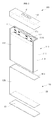
- FIG. 2 is an exploded perspective view of the polymer battery pack 100 in FIG. 1
- the polymer battery pack 100 in the present embodiment includes a core pack 110 having a structure in which a protection circuit member 117 is attached to a bare cell 111, a case 120 into which the core pack 110 is combined to expose externally the protection circuit member 117 and a bottom surface which is in an opposite direction to the protection circuit member 117, a bottom cover 130 which covers the bottom surface exposed through the case 120, and a resin which wraps the protection circuit member 117 exposed through the case 120.
- the bare cell 111 included in the core pack 110 may be a conventional lithium polymer battery.
- a pouch 112 forms an external appearance, and three surfaces of the pouch 112 except a surface of a lower part are heat-welded with one another.
- two surfaces facing each other among the three surfaces of the pouch 112 are folded to minimize a size of the pouch 112.
- the folded parts of the pouch 112 are defined as folded parts 113.
- the protection circuit member 117 is seated.
- the protection circuit member 117 includes a printed circuit board 117a, one or more electronic parts 117b installed on the printed circuit board 117a, and one or more electrode terminals 117c installed on the printed circuit board 117a.
- the case 120 is in a form of a tube or a sleeve of which a surface in a direction to the protection circuit member 117 and a surface in an opposite direction to the protection circuit member 117, that is a bottom surface, are open. More specifically, the case 120 includes two long-sided parts 121 which each have a comparatively large area and are separated from each other by a predetermined distance. In addition, the case 120 includes two short-sided parts 122 which connect both ends of the long-sided parts 121 and each have a comparatively small area. The case 120 has openings 123 which are open in upward and downward directions by the long-sided and short-sided parts 121 and 122.
- the case 120 including the long-sided and short-sided parts 121 and 122 may be formed by injection molding of polyamid, polyurethane, plastic, fiber-reinforced plastic, engineering plastic or the equivalents.
- the case 120 may be formed by deep-drawing a metal master into one body or welding two metal masters together.
- the case 120 may be formed from one of aluminum-based, magnesium-based, steel-based, stainless steel-based metals and the equivalents which can be deep-drawn and are lightweight and have a high strength.
- the case 120 may be formed to have a thickness of approximately 0.1 - 0.2 mm to include the core pack 110 having a high capacity of 850 mAh or more.
- a rib space of approximate 0.8 mm, that is 0.4 mm for each side is required in a conventional battery pack, whereas, in the embodiment of the present invention, space for ultrasonic welding is not required, so that the core pack 110 having a larger size than a size of the core pack in a conventional polymer battery pack can be included.
- the thickness of the case 120 is 0.1 mm or less, required strength cannot be obtained, while when the thickness of the case 120 is 0.2 mm or more, the case would be too thick and heavy, although the strength required can be obtained.
- a total height of the case 120 may be less than that of the core pack 110.
- the protection circuit member 117 and some area of the core pack 110 neighboring the protection circuit member 117 are exposed externally and protruded to a predetermined length through the case 120.
- a bottom surface of the core pack 110 is also exposed externally through a lower part of the case 120.
- the bottom cover 130 is attached to the lower part of the case 120, so that the core pack 110 cannot be moved away through the lower part of the case 120.
- the bottom cover 130 is attached to a lower part of the long-sided and short-sided parts 121 and 122 of the case 120 by a conventional adhesive or welding.
- the bottom cover 130 may be formed from one of polyamid, polyurethane, plastic, fiber-reinforced plastic, engineering plastic, aluminum-based, magnesium-based, steel-based, stainless steel-based metals and the equivalents. However, material of the bottom cover 130 is not limited thereto.
- the bottom cover 130 may be formed to have a thickness of approximately 0.1 - 0.2 mm. When the thickness of the bottom cover 130 is 0.1 mm or less, a required strength cannot be obtained, while when the thickness of the bottom case 130 is 0.2 mm or more, the case would generally be too thick and heavy, although the strength required would be obtained.
- the resin 140 covers the protection circuit member 117 which is installed to an opposite side, that is an upper part, to the bottom cover 130 and some areas of the core pack 110 neighboring the protection circuit member 117.
- the electrode terminal 117c of the protection circuit member 117 which is connected to an external apparatus is exposed externally through an opening 141 of the resin 140.
- the resin 140 may be a hot melt resin or the equivalent which melts at a temperature of about 140 ⁇ 160 °C.
- material of the resin 140 is not limited thereto, for example, the resin could be an epoxy that cures at room temperature.
- the resin 140 is illustrated as a separate component from the protection circuit member 117 in FIG. 2, in practice, the resin is formed in a metal mold (not shown) by a molding process.
- the core pack 110 is combined into the case 120, and the combined case is disposed in the metal mold, and the resin 140 is formed as a substantially rectangular parallelepiped shape as illustrated in FIG. 2 by filling and hardening the resin 140 having a high temperature and a high pressure into the protection circuit member 117 and some areas of the core pack 110 neighboring the protection circuit member 117.
- FIG. 3 is a perspective view of a connection of the protection circuit member 117 and the bare cell 111 in the polymer battery pack in FIG. 1.
- conductive electrode tabs 116a and 116b are exposed and extended to a predetermined length into an area 114 located upward from the pouch 112 of the bare cell 111.
- conductive pads 117d and 117e are formed on the printed circuit board 117a of the protection circuit member 117 for an electrical connection. Accordingly, the conductive pads 117d and 117e and the conductive electrode tabs 116a and 116b are mutually connected by ultrasonic welding, laser welding, resistance welding, soldering, etc.
- the protection circuit member 117 is stably seated in the upward area 114 of the bare cell 111 by the connection.
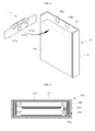
- FIG. 4 is a sectional view of the polymer battery pack 100 taken along section line 4-4 of FIG. 1.
- an electrode assembly 115 which has been wound multiple times is included inside the pouch 112 included in the bare cell 111.
- the folded parts 113 formed on both sides of the pouch 112 facing each other are bent to a predetermined direction, so that an area occupied by the bare cell 111 can be minimized.
- outer surfaces of the pouch 112 are wrapped by the case 120.
- the case 120 including the long-sided and short-sided parts 121 and 120 wraps the outer surfaces of the pouch 112 completely.
- the external strength of the polymer battery pack is greatly improved by directly ensconcing the pouch 112 of the bare cell 111 having a low strength with the case 120 having a high strength. Moreover, since an additional space for ultrasonic welding is not required in the case 120, a comparatively large-sized bare cell 111 can be easily included, so that total capacity of the polymer battery pack 100 is increased.
- FIG. 5 is a sectional view of the polymer battery pack 100 taken along section line 5-5 of FIG. 1.
- the polymer battery pack 100 formed by being wrapped by the case 120, the bottom cover 130, and the resin 140 includes the bare cell 111 and the protection circuit member 117.
- the bare cell 111 and the protection circuit member 117 are together called the core pack 110.
- An outer surface of bare cell 111 is wrapped by the pouch 112.
- a metal layer 112a is disposed in the middle, and a first insulation layer 112b is formed on one side, and a second insulation layer 112c is formed on the other side.
- the metal layer 112a may be formed from one of aluminum, steel, stainless steel, or the equivalent.
- the first insulation layer 112b may be selected from one of cast polypropylene (CPP) and the equivalents
- the second insulation layer 112c may be selected from one of nylon, polyethylene terephthalate (PET), and the equivalents.
- materials of the first and second insulation layers 112b and 112c are not limited thereto.
- the electrode assembly 115 includes a first electrode 115a, a separator 115b, and a second electrode 115c.
- the electrode assembly 115 has a structure in which the components described above are wound multiple times.
- a first current collector is disposed in the middle and a first active material is coated on a surface of the first current collector.
- a second current collector is disposed in the middle and a second active material is coated on a surface of the second current collector.
- the first electrode 115a may be an anode and the first current collector may be an aluminum foil and the first active material may be a lithium oxide.
- the second electrode 115b may be a cathode, and the second current collector may be a copper foil and the second active material may be a carbon based material.
- a first conductive electrode tab 116a is connected to the first current collector of the first electrode 115a and extended to a predetermined length outside the pouch 112
- a second conductive electrode tab 116b is connected to the second current collector of the second electrode 116b and extended to a predetermined length outside the pouch 112.
- FIG. 5 only the first conductive electrode tab 116a of conductive electrode tabs 116a and 116b is shown.
- a separator 115b made of a macroporous material through which only lithium ions can pass is interposed.
- the protection circuit member 117 is electrically connected to the conductive electrode tab 116a which is extended to a predetermined length outside the pouch 112.
- a conductive pad 117d is formed on the printed circuit board 117a included in the protection circuit member 117.
- the conductive pad 117d is electrically connected to the conductive electrode tab 116a.
- another conductive pad 117e is connected to another conductive electrode tab 116b.
- an electrode terminal 117c is formed and the electrode terminal 117c is installed on an insulator 117f.
- the electrode terminal 117c and the printed circuit board 117a are electrically connected with each other.
- the electrode terminal 117c is exposed externally through an opening 141 formed in the resin 140.
- FIG. 6 is a perspective view of a polymer battery pack according to another embodiment of the present invention.
- most external surfaces of the polymer battery pack 200 in the present embodiment are wrapped by a case 220 and a bottom cover 230.
- heights of the polymer pack 200 and the case 220 are almost the same.
- the polymer pack 200 has a structure in which a resin 240 is exposed externally through an upper part of the case 220, and an electrode terminal 217c is exposed through the resin 240.
- only an upper surface of the resin 240 is exposed, while in the polymer battery pack 100 illustrated in FIG. 1, surfaces of four sides are exposed together including the upper surface.
- FIG. 7 is an exploded perspective view of the polymer battery pack in FIG. 6.
- the protection circuit member 217 which has been molded with the resin 240 in advance is combined with the case 220.
- components constituting the protection circuit member 217 such as a printed circuit board 217a and an electronic component 217b are molded with the resin 240 or the equivalent of the resin 240 in advance.
- other conductive electrode tabs 217f and 217g which are extended outside the resin 240 are formed.
- the conductive electrode tabs 217f and 217g are electrically connected to conductive electrode tabs 216a and 216b formed on the bare cell 211.
- a height of the bare cell 211 is a little less than that of the case 220.
- the polymer battery pack 200 is fully assembled by combining the protection circuit member 217 with an upper space of the case 220, while connecting conductive electrodes tabs 217f and 217g of the protection circuit member 217 which has been molded with the resin 240 to the conductive electrode tabs 216a and 216b of the bare cell 211 which has been completely combined with the case 220 and the bottom cover 230.
- the polymer battery pack 200 in the current embodiment has a structure in which the case 220 and the bottom cover 230, both of which have a high strength, wrap most of the outer surfaces of other components, so that strength and reliability of the polymer battery pack 200 is improved remarkably.
- a waterproof adhesive layer may be formed on a boundary between the molded resin 240 and the case 200, since a foreign substance or water may penetrate through a gap between the resin 240, which has molded the protection circuit board 217 in advance, and the case 220.
- FIG. 8A is an exploded perspective view of a polymer battery pack according to another embodiment of the present invention.
- FIG. 8B is an exploded perspective view of a case in FIG. 8A
- FIG. 8C is a sectional view of a connection of a bare cell and a case.
- the case 320 of the polymer battery pack 300 is different from the cases 120 and 220 of the polymer packs 100 and 200 described above.
- the case 320 used in the polymer battery pack 300 includes two long-sided parts 321a and 321b which have comparatively large areas and are separated to a predetermined distance from each other by two short-sided parts 322a and 322b which are connected to both sides of the long-sided parts 321a and 321b and have comparatively small areas and round shapes, and a bottom part which covers the long-sided parts 321a and 321 b and the short-sided parts 322a and 322b.
- an opening 324 is formed, so that a core pack 310 can be easily combined into the case 320.
- a height of the case 320 is less than that of the core pack 310. Accordingly, after the core pack is combined into the case 320, a protection circuit member 317 which is connected to the core pack 310 and a neighboring area of the protection circuit member 317 protrude to a predetermined length through the case 320.
- the two long-sided parts 321a and 321b and the short-sided part 322a are integrated into one body, and may be formed from one of steel, stainless steel, aluminum, plastic and the equivalents.
- One remaining short-sided part 322b of the case 320 and the bottom part 323 may be formed from resin. After the two long-sided parts 321 a and 321 b and the short-sided part 322a are formed, the remaining short-sided part 322b and the bottom part 323 are formed in a metal mold using resin to form the case 320.
- both sides of the resin 340 wrapping the protection circuit member 317 and an upper portion of the core pack 310 neighboring the protection circuit member 317 are formed in a substantially rounded form.
- the resin 340 is filled into spaces between the round-shaped short-sided parts 322a and 322b and a folded part 313 of a bare cell 311, respectively. Accordingly, a combining strength of the resin 340, the bare cell 311, and the case 320 is improved remarkably.
- the short-sided parts 322a and 322b are described as formed in a rounded shape, they are not limited thereto, that is, the short-sided parts 322a and 322b can be formed in polygonal shapes. As such the spaces between the short-sided parts 322a and 322b and the folded part 313 are filled with resin according to aspects of the present embodiment.
- FIG. 9A is an exploded perspective view of a polymer battery pack according to another embodiment of the present invention
- FIG. 9B is a sectional view of a connection of a bare cell and a case according to the embodiment.
- a protection circuit member 417 which has been molded with a resin 440 is combined into a case 420.
- components such as a printed circuit board 417a and an electronic part 417b constituting the protection circuit member 417 are molded with the resin 440 or an equivalent of the resin 440 in advance.
- other conductive electrode tabs 417f and 417g which are extended to a predetermined length outside the resin 440 are formed.
- the conductive electrode tabs 417f and 417g are electrically connected to conductive electrode tabs 416a and 416b formed on a bare cell 411.
- a height of the bare cell 411 is a little less than that of the case 420.
- the polymer battery pack 400 is fully assembled by combining the bare cell 411 into the case 420 completely, electrically connecting conductive electrode tabs 417f and 417g to the conductive electrode tabs 416a and 416b, and combining the protection circuit member 417 with an upper space of the case 420.
- the case 420 includes two long-sided parts 421 a and 421 b which have comparatively large areas and are separated by a predetermined distance from each other by two short-sided parts 422a and 422b which are connected to both ends of the long-sided parts 421 a and 421 b, which have comparatively small areas and round shapes, and a bottom part 423 which covers the long-sided parts 421a and 421b and the short-sided parts 422a and 422b.
- the opening 424 is formed, so that the bare cell 411 can be easily combined into the case 420.
- a predetermined space S may be formed between the short-sided parts 422a and 422b of the case 420, and a folded part 413 of the bare cell 411.
- the space S is formed, since the protection circuit member 417 which has been molded with the resin 440 is combined into the case 420. In other words, since no molding process is performed after combining the bare cell 411 and the protection circuit member 417 molded with the resin 420 into the case 420, the space S is formed.
- the short-sided parts 422a and 422b are described as round shapes, it is understood they could be polygonal shapes.
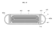
- the space S, formed between the short-sided parts 422a and 422b can contain additional structural stiffeners to add strength to the polymer battery pack as shown in FIG. 15.
- FIG. 10 is a flowchart of a method of manufacturing a polymer battery pack according to an embodiment of the present invention. Examples of the polymer battery pack produced by the method shown in FIG. 10 are shown in FIGS. 1 and 11G.
- the method of manufacturing the polymer battery pack according to this embodiment of the present invention includes a generation stage S101 of a bare cell, a forming stage S102 of a core pack, a combination stage S103 of a case, an attachment stage S104 of a bottom cover, and a molding stage S105 of a resin.
- an electrode assembly is inserted in a pouch, and the pouch is sealed (S101).
- a protection circuit member including one or more electrode terminals is attached to an outer surface of the bare cell (S102).
- the core pack is combined inside, and, more specifically, the core pack is combined into the case having a form of a tube or a sleeve, so that the protection circuit member and a bottom surface which is located in the opposite direction of the protection circuit member are exposed externally (S103).
- the attachment stage S104 of the bottom cover the bottom surface of the case is covered by the bottom cover (S104).
- the molding stage S105 of a resin the protection circuit member exposed through the case and a region of the bare cell on which the protection circuit member is seated are molded by a resin, so that an electrode terminal of the protection circuit member is exposed externally (S105).
- FIGS. 11A to 11G are diagrams of the method of manufacturing the polymer battery pack in FIG. 10 illustrating stages of the manufacturing method. Referring to FIGS. 11A and 11B, the forming stage S101 of the bare cell is illustrated.
- a first electrode 115a, a separator 115b, and a second electrode 115c are wound, and an electrode assembly 115 in which first and second conductive electrode tabs 116a and 116b are connected to first and second electrodes 115a and 115c, respectively, is inserted into a pouch 112 and the pouch 112 is sealed.
- the first and second conductive electrode tabs 116a and 116b are extended and exposed to a predetermined length outside the pouch 112.
- surfaces of the pouch 112 having the electrode assembly 115 in the center in three directions are heat-welded, so that the electrode assembly 115 is not detached outside.
- a surface in one direction which is not heat-welded is a portion in which the pouch 112 is folded and accordingly does not need to be heat-welded. After the heat-welding, both sides facing each other are bent to a predetermined angle to form a folded part 113 for minimizing a size of the pouch 112.
- the protection circuit member 117 is connected to the bare cell 111 mechanically and electrically.
- the protection circuit member 117 including a printed circuit board 117a, an electronic component 117b, and an electrode terminal 117c is connected mechanically and electrically to the conductive electrode tabs 116a and 116b of the bare cell 111 exposed outside the pouch 112.
- the protection circuit member 117 is located in an area defined as the upper region 114 of the pouch 112 of the bare cell 111.
- a structure in which the protection circuit member 117 is seated on the bare cell 111 is called a core pack 110.
- the core pack 110 is combined into a case 120 which includes a long-sided part 121 and a short-sided part 122 and is open in directions upward and downward.
- the case 120 is formed from polyamid, polyurethane, plastic, fiber-reinforced plastic, engineering plastic, aluminum, steel, stainless steel or the equivalent, and has a thickness of about 0.1 to 0.2 mm.
- a height of the case 120 is set to have approximately 80 to 95 % of the height of the core pack 110, so that the protection circuit member 117 and a neighboring area of bare cell 111 on which the protection circuit member 117 is seated are exposed through the case 120.
- a bottom surface 110 of the core pack 110 is exposed externally through a lower part of the case 120.
- the attachment stage S104 of the bottom cover is illustrated.
- the bottom cover 130 is attached to a lower portion of the case 120.
- the bottom cover 130 may be attached to a lower portion of the long-sided and short-sided parts 121 and 122 of the case 120 by a conventional adhesive, welding, or the equivalent.
- a method of the attachment of the bottom cover 130 is not limited thereto.
- the bottom cover 130 is formed from polyamid, polyurethane, plastic, fiber-reinforced plastic, engineering plastic, aluminum, steel, stainless steel or the equivalent for acquiring a strength, and the thickness of the bottom cover 130 is approximately 0.1 to 0.2 mm. In this method, all surfaces of the core pack 110 in side and downward directions except an upward direction are wrapped by the case 120 and the bottom cover 130.
- FIG. 11 F the molding stage S105 of the resin is illustrated.
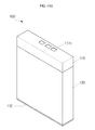
- FIG. 11G the completed status of the polymer battery pack 100 is illustrated.
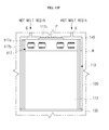
- the core pack 110 wrapped by the case 120 and the bottom cover 130 as described above is seated on a predetermined metal mold M.
- a predetermined gap between the protection circuit member 117 or the portion of the core pack 110 neighboring the protection circuit member 117 and the metal mold M is formed.
- a high-temperature and high-pressure resin 140 is filled through a gate G, and thereafter the resin 140 is cooled at a predetermined temperature and hardened.
- the electrode terminal 117c of the protection circuit member 117 is disposed to contact a protrusion P formed on a metal mold M, so that the electrode terminal 117c is exposed outside the resin 140.
- the resin 140 may be a hot-melt resin or the equivalent melting at a temperature of about 140 to 160 °C.
- material of the resin 140 is not limited thereto.
- an epoxy resin can be used that cures at room temperature.
- FIG. 12 is a flowchart of a manufacturing method of a polymer battery pack according to another embodiment of the present invention. This method illustrated in FIG. 12 produces, for example, the polymer battery pack shown in FIG. 6.
- the manufacturing method of the polymer battery pack 200 includes a forming stage S111 of a bare cell, a molding stage S112 of a core pack, a combination stage S113 of a case, a combination stage S114 of a bottom cover, and a connection stage S115 of a protection circuit member.
- a forming stage S111 of the bare cell an electrode assembly is inserted into a pouch and the pouch is sealed.
- a protection circuit member which has one or more electrode terminals is molded with a resin, so that the electrode terminals are exposed externally.
- the bare cell is combined into the case, so that an area on which the protection circuit member in which the resin has been molded is seated and a bottom surface in an opposite direction are exposed outside the case (S113).
- the bottom cover is attached to cover the bottom surface of the core pack exposed through the case (S114).
- the resin-molded protection circuit member is seated and connected to a surface of the bare cell exposed through the case (S115).
- a height of the case 200 is the same as that of the bare cell 211.
- the bare cell 211 and the case 220 have the same height. Accordingly, when the bare cell 211 is combined into the case 220, some portion of the bare cell 211 is exposed externally through the case 220, but not extended outside the case 220.
- the protection circuit member 217 which has been molded with the resin 240 is electrically connected to the conductive electrode tabs 216a and 216b exposed externally through the bare cell 211 and combined in a space arranged in the case 220, concurrently. If this method is used, the completed polymer battery pack 200 has a form illustrated in FIGS. 6 and 7. Accordingly, most of the polymer battery pack 200 is wrapped by the case 220, the bottom cover 230, and the resin 240. Accordingly, strength and reliability of the polymer battery pack 200 is improved remarkably.
- FIG. 13 is a flowchart of a manufacturing method of a polymer battery pack according to another embodiment of the present invention. Examples of the polymer battery pack produced according to this embodiment are shown in FIGS. 1 and 8A through 8C.
- the manufacturing method of the polymer battery pack 300 includes a forming stage S121 of a bare cell, a forming stage of a core pack S122, a combination stage of a case S123, and a molding stage S124 of a resin.
- a forming stage S121 of the bare cell an electrode assembly is inserted into a pouch and the pouch is sealed (S121).
- a protection circuit member having at least one electrode terminal is connected to an outer surface of the bare cell (S122).
- the core pack is combined into the case, so that the protection circuit member is exposed outside the case (S123).
- the molding stage S124 of the resin the protection circuit member exposed through the case is molded with the resin, so that the electrode terminals of the protection circuit member are exposed externally.
- the case 320 used in the combination stage S123 of the case includes long-sided parts 321a and 321 b which have predetermined areas and are separated to a predetermined distance from each other by short-sided parts 322a and 322b which are connected to both ends of the long-sided parts 321a and 321b, which have smaller areas than the long-sided parts 321a and 321b, and have round shapes and a bottom part 323 which covers the long-sided parts 321a and 321b and the short-sided parts 322a and 322b at an area located in the opposite direction to the protection circuit member 317.
- two long-sided parts 321a and 321b and at least one short-sided parts 322a may be formed from stainless steel and the bottom part 323 and the other short-sided part 322b may be formed from resin.
- FIG. 14 is a flowchart of a manufacturing method of a polymer battery pack according to another embodiment of the present invention. This embodiment of the invention produces, for example, the polymer battery pack shown in FIGS. 9A and 9B.
- the manufacturing method of the polymer battery pack includes a generation stage S131 of a bare cell, a molding stage S132 of the resin, a combination stage S133 of a case, and a connection stage of a protection circuit member.
- the generation stage S131 of the bare cell an electrode assembly is inserted in a pouch and the pouch is sealed.
- a protection circuit member which has at least one electrode terminal is molded with the resin, so that the electrode terminal is exposed externally.
- the combination stage S133 of the case the bare cell is combined into the case so that an area on which the resin-molded protection circuit member is seated is exposed outside the case.
- the connection stage S134 of the protection circuit member the resin-molded protection circuit member is seated on and connected to a surface of the bare cell exposed through the case.
- the case 420 used in the combination stage S133 of the case includes long-sided parts 421a and 421 b which have a predetermined area and are separated to a predetermined distance from each other by short-sided parts 422a and 422b which are connected to both ends of the long-sided parts 421a and 421b, which have smaller areas than the areas of the long-sided parts 421a and 421b, and round shapes and a bottom part 423 which is commonly connected to the long-sided parts 421a and 421b and the short-sided parts 422a and 422b at an area located in the opposite direction to the protection circuit member 417.
- two long-sided parts 421a and 421b facing each other and at least one short-sided part 422a may be formed from stainless steel and the bottom part 423 and the other short-sided part 422b may be formed from resin.
- the resin-molded protection circuit member 417 is electrically and mechanically connected to the bare cell 411 and mechanically connected to the case 420. Accordingly, the resin is not filled in between the short-sided parts 422a and 422b and a folded part 413 of the bare cell 411, so that a predetermined space S can be formed.
- the polymer battery pack and the manufacturing method thereof improves strength and reliability of the polymer battery pack by wrapping the bare cell which is in a form of a pouch and is weak with a case having a high strength.
- a thickness of the case can be reduced by 0.1 to 0.2 mm, so that capacity of the battery corresponding to the reduced space can be increased.
- a space of approximately 0.8 mm, 0.4 mm per one side is required for ultra-sonic welding
- the space for ultra-sonic welding is not required and accordingly, it is possible to include a bare cell or a core pack having a capacity of 850 mAh or more.
Landscapes
- Chemical & Material Sciences (AREA)
- Electrochemistry (AREA)
- General Chemical & Material Sciences (AREA)
- Chemical Kinetics & Catalysis (AREA)
- Engineering & Computer Science (AREA)
- Manufacturing & Machinery (AREA)
- Materials Engineering (AREA)
- Inorganic Chemistry (AREA)
- Physics & Mathematics (AREA)
- Condensed Matter Physics & Semiconductors (AREA)
- Dispersion Chemistry (AREA)
- General Physics & Mathematics (AREA)
- Battery Mounting, Suspending (AREA)
- Sealing Battery Cases Or Jackets (AREA)
- Connection Of Batteries Or Terminals (AREA)
Abstract
Description
- Aspects of the present invention relate to a polymer battery pack and, more particularly, to a polymer battery pack capable of improving external strength and increasing capacity and a manufacturing method of the polymer battery pack.
- Generally, a polymer battery pack includes a core pack which is a protection circuit member connected to a bare cell having a form of a pouch and a plastic case in which the core pack is inserted and of which all seams are ultrasonically welded. Here, the bare cell having the form of the pouch is a lithium polymer battery having a structure in which an electrode assembly including a cathode, a separator, an anode, and polymer electrolyte is accommodated into the pouch made of cast polypropylene (CPP), aluminum, nylon, or polyethylene terephthalate (PET). The polymer battery pack or a lithium polymer battery is so named to differentiate it from a lithium ion battery pack or a lithium ion battery which uses a liquid electrolyte.
- However, the lithium polymer battery pack may be easily damaged by external forces to decrease reliability of the battery pack, since the pouch constituting the bare cell and a plastic case wrapping the pouch are weak. In other words, aluminum used for the pouch is in a form of a foil and the plastic case wrapping the pouch is thin, so that the pouch and the plastic case may be easily deformed and easily pierced by a sharp instrument such as a nail or a needle. When the polymer battery pack is deformed or pierced by a sharp instrument, a smoke, a flame, or an explosion may occur due to an internal short.
- In addition, along seams of the plastic case in the polymer battery pack, a rib space is required for ultrasonic welding the plastic case, and the space occupies at least 0.8 mm or more. Accordingly, a size of the core pack, which is the bare cell, inserted into the polymer battery pack is decreased, and this results in a decrease in the capacity of the battery pack. In other words, the size of the core pack which can be inserted into the plastic case is comparatively very small compared to the size of the plastic case, so that the core pack of high capacity cannot be inserted into the plastic case. In practice, a conventional polymer battery pack cannot accommodate the core pack of approximately 680 mAh capacity or more.
- Aspects of the present invention provide a polymer battery pack capable of improving external strength and increasing capacity and a manufacturing method of the polymer battery pack.
- According to an aspect of the invention there is provided a polymer battery pack comprising core pack formed by attaching a protection circuit member to a bare cell, case combining with the core pack and exposing the protection circuit member externally, and a resin wrapping the protection circuit member exposed through the case.
- The protection circuit member and the core pack neighboring the protection circuit member protrude through the case by a predetermined length.
- The bare cell may comprise an electrode assembly having a first electrode, a separator, and a second electrode, two electrode tabs connected to the first and second electrodes, respectively and extended externally to a predetermined length, and a pouch wrapping the electrode assembly and having the electrode tabs extended to a predetermined length externally.
- The pouch may comprise a first insulation layer, a metal layer, and a second insulation layer. The first insulation layer may be cast polypropylene (CPP), the metal layer may be one selected from the group consisting of aluminum, steel, and stainless steel, and the second insulation layer may be one selected from the group consisting of nylon and polyethylene terephthalate (PET).
- The protection circuit member may comprise a printed circuit board on which one or more electronic components are installed, and one or more electrode terminals installed on one side of the printed circuit board and exposed outside the resin.
- In another aspect of the invention the protection circuit member may be electrically connected to the electrode tabs. In yet another embodiment the protection circuit member may be mechanically connected to the electrode tabs. The electrode tabs may be connected to conductive pads on the protective circuit member.
- In one aspect of the invention the case is formed to have a tube shape of which one side located in an opposite direction to the protection circuit member is open. The polymer battery pack may further comprise a bottom cover to cover one side of the case located in an opposite direction to the protection circuit member.
- In another aspect of the invention the case may comprise long-sided parts separated by a predetermined distance from each other and having a predetermined area, and short-sided parts connecting both ends of the long-sided parts with each other and having areas smaller than the area of the long-sided parts. The short-sided parts may be in an approximately rounded shape. In another embodiment the short-sided parts may be in a polygonal shape.
- The case may be composed of one selected from the group consisting of polyamid, polyurethane, plastic, fiber reinforced plastic, engineering plastic, aluminum, steel, stainless steel, and combinations thereof. The case may be formed to have a thickness of 0.1 to 0.2 mm
- The bottom cover may be formed from one selected from the group consisting of polyamid, polyurethane, plastic, fiber reinforced plastic, engineering plastic, aluminum, steel, stainless steel, and combinations thereof. The bottom cover may be formed to have a thickness of 0.1 to 0.2 mm. In one aspect of the invention the bottom cover is attached or welded to the case.
- The resin may be a hot melt resin melting at a temperature of 140 to 160 °C. Preferably, the resin is an epoxy resin curing at room temperature.
- The protection circuit member and a portion of the bare cell on which the protection circuit member is installed may be exposed externally, and the protection circuit member and the portion of the bare cell on which the protection circuit member is installed may be molded together with resin.
- The protection circuit member may be formed by molding with resin in advance, and the resin-molded protection circuit member is electrically connected to the core pack by being combined with the case. Such a polymer battery pack may further comprise a waterproof seal between the resin-molded protection circuit member and the case. At least one electrode terminal may be formed on the protection circuit member, and the electrode terminal may be exposed outside the resin. In another aspect of the invention at least one electrode terminal may be formed on the protection circuit member, and the electrode terminal may be exposed outside the resin.
- In one embodiment the case comprises long-sided parts separated by a predetermined distance from each other and having a predetermined area, short-sided parts connecting both ends of the long-sided parts with each other and having areas smaller than the area of the long-sided parts, and a bottom part commonly connected to the long-sided and short-sided parts and located at an area in an opposite direction of the protection circuit member. The short-sided parts may be in an approximately rounded shape. Both sides of the resin wrapping the protection circuit member and an upper portion of the core pack neighboring the protection circuit may be formed in substantially rounded form. The two long-sided parts facing each other and at least one of the short-sided parts connected to the two long-sided parts may be formed from stainless steel, and the bottom part and one remaining short-sided part may be formed from resin. A space between the core pack and the short-sided parts of the case may be filled together with resin wrapping the protection circuit member. In another embodiment the space between the core pack and the short-sided parts of the case is filled together with resin wrapping the protection circuit member. A predetermined space may be formed between the core pack and the short-sided parts of the case. The space between the core pack and the short-sided parts of the case may be filled with a stiffener.
- According to an aspect of the present invention, there is provided a manufacturing method of a polymer battery pack comprising: forming a bare cell by inserting an electrode assembly into a pouch and sealing the pouch; forming a core pack by connecting a protection circuit member having at least one electrode terminal to an outer surface of the bare cell; combining the core pack into the case to expose the protection circuit member and a bottom surface in the opposite direction to the protection circuit member; attaching a bottom cover to cover the bottom surface of the core pack exposed through the case; and molding the protection circuit member exposed through the case with resin to expose externally the electrode terminal of the protection circuit member.
- As described above, the polymer battery pack and the manufacturing method thereof according to the present invention improves strength and reliability of the polymer battery pack by wrapping the bare cell having a form of a pouch which is weak with a case having high strength and molding the protection circuit member with the resin.
- In addition, according to an aspect of the present invention, a thickness of the case can be reduced to 0.1 to 0.2 mm, so that the capacity of the battery can be increased remarkably. In other words, while in a case of a conventional polymer battery pack, a space of approximate 0.8 mm is required for ultrasonic welding, according to aspects of the present invention, the space for ultrasonic welding is not required and accordingly, it is possible to include a bare cell or a core pack having a capacity of 850 mAh or more.
- The step of combining into the case may comprise combining the core pack to the protection circuit member and a tube-shaped case which has an opening in an opposite direction to the protection circuit member. The combining into the case may further comprise connecting long-sided parts separated to a predetermined distance from each other with short-sided parts connecting both ends of the long-sided parts. In one aspect of the invention the combining into the case, includes forming the case from one of polyamid, polyurethane, plastic, fiber reinforced plastic, engineering plastic, aluminum, steel, stainless steel, and combinations thereof. The step of combining into the case may include forming the case to a thickness of 0.1 to 0.2 mm.
- The step of attaching the bottom cover may comprise forming the cover from one of polyamid, polyurethane, plastic, fiber reinforced plastic, engineering plastic, aluminum, steel, a stainless steel, and combinations thereof. Attaching the bottom cover may include forming the bottom cover to have a thickness of 0.1 to 0.2 mm. Attaching the bottom cover may include welding or applying adhesive.
- The resin molding further comprises injecting hot-melt resin at a temperature of 140 to 160 °C and may comprise injecting an epoxy resin that cures at room temperature.
- In another embodiment of the invention a manufacturing method of a polymer battery pack comprises the steps of forming a bare cell by inserting an electrode assembly into a pouch and sealing the pouch, molding a protection circuit member having at least one electrode terminal with resin to expose the electrode terminal externally, combining the bare cell into a case to expose an area on which the resin-molded protection circuit member is to be seated and a bottom surface opposite that of the area outside the case, attaching a bottom cover to cover the bottom surface of the bare cell exposed through the case, and seating and connecting the resin-molded protection circuit member on/to the surface of the bare cell exposed through the case.
- In yet another embodiment of the invention a manufacturing method of a polymer battery pack comprises the steps of forming a bare cell by inserting an electrode assembly into a pouch and sealing the pouch, forming a core pack by connecting a protection circuit member having at least one electrode terminal to an outer surface of the bare cell, combining the core pack into a case to expose the protection circuit member outside the case, and molding the protection circuit member exposed through the case with resin to expose externally the electrode terminal of the protection circuit member.
- Between the combing and the molding step a step of attaching a bottom cover to cover the bottom surface of the core pack exposed through the case may be provided.
- The combining step may further include a bottom surface located in the opposite direction to the protection circuit member outside the case.
- Combining the core pack into the case may comprise connecting long-sided parts separated to a predetermined distance from each other by round shaped short-sided parts at both ends of the long-sided parts, each having an area smaller than an area of one of the long-sided parts; and connecting a bottom part commonly to the long-sided and short-sided parts at an area located in an opposite direction to the protection circuit member. In another aspect of the invention combining of the core pack into the case comprises forming the long-sided parts facing each other and at least one of the short-sided parts connected to the long-sided parts from stainless steel; and forming the bottom part and one remaining short-sided part from resin.
- Resin molding may include filling a space between the core pack and the short-sided parts of the case with resin.
- In yet another aspect of the invention the manufacturing method of a polymer battery pack may comprise forming a bare cell by inserting an electrode assembly into a pouch and sealing the pouch; molding a protection circuit member having at least one electrode terminal with resin to expose the electrode terminal externally; combining the bare cell into a case to expose an area on which the resin-molded protection circuit member is to be seated outside the case; and seating and connecting the resin-molded protection circuit member on/to the area of the bare cell exposed through the case.
- Combining into the case may comprise long-sided parts separated by a predetermined distance from each other and having a predetermined area; short-sided parts at both ends of the long-sided parts, the short-sided parts having rounded areas smaller than the area of the long-sided parts; and connecting a bottom part commonly to the long-sided and short-sided parts as an area located on an opposite side of the bare cell as that of the protection circuit member.
- Seating and connecting includes forming a waterproof seal between the resin-molded protection circuit member and the case.
- Combining into the case includes forming the two long-sided parts facing each other and at least one of the short-sided parts connected to the two long-sided parts from stainless steel, and forming the bottom part and one remaining short-sided part from resin.
- The combining may step further include a bottom surface opposite that of the area outside the case.
- A step of attaching a bottom cover to cover the bottom surface of the bare cell exposed through the case may further be provided between the combining and the seating step.
- Additional aspects and/or advantages of the invention will be set forth in part in the description which follows and, in part, will be obvious from the description, or may be learned by practice of the invention.
- These and/or other aspects and advantages of the invention will become apparent and more readily appreciated from the following description of the embodiments, taken in conjunction with the accompanying drawings of which:
- FIG. 1 is a perspective view of a polymer battery pack according to an embodiment of the present invention;
- FIG. 2 is an exploded perspective view of the polymer battery pack in FIG. 1;
- FIG. 3 is a perspective view of connection of a protection circuit member and a bare cell in the polymer battery pack in FIG. 1;
- FIG. 4 is a sectional view of the polymer battery pack taken along section line 4-4 of FIG. 1;
- FIG. 5 is a sectional view of the polymer battery pack taken along section line 5-5 of FIG. 1;
- FIG. 6 is a perspective view of a polymer battery pack according to another embodiment of the present invention;
- FIG. 7 is an exploded perspective view of the polymer battery pack in FIG. 6;
- FIG 8A is an exploded perspective view of a polymer battery pack according to another embodiment of the present invention;
- FIG. 8B is an exploded perspective view of a case in FIG. 8A;
- FIG. 8C is a sectional view of a connection of a bare cell and the case in FIG. 8A;
- FIG. 9A is an exploded perspective view of a polymer battery pack according to another embodiment of the present invention;
- FIG. 9B is a sectional view of a connection of a bare cell and a case in FIG 9A;
- FIG. 10 is a flowchart of a method of manufacturing a polymer battery pack according to an embodiment of the present invention;
- FIGS. 11Ato 11G are diagrams of the method of manufacturing the polymer battery pack in FIG. 10 illustrating stages of the manufacturing method;
- FIG. 12 is a flowchart of a manufacturing method of a polymer battery pack according to another embodiment of the present invention;
- FIG. 13 is a flowchart of a manufacturing method of a polymer battery pack according to another embodiment of the present invention;
- FIG. 14 is a flowchart of a manufacturing method of a polymer battery pack according to another embodiment of the present invention;
- FIG. 15 is a sectional view of a connection of a bare cell and a case in FIG 9A.
- Reference will now be made in detail to the present embodiments of the present invention, examples of which are illustrated in the accompanying drawings, wherein like reference numerals refer to the like elements throughout. The embodiments are described below in order to explain the present invention by referring to the figures.
- FIG. 1 is a perspective view of a polymer battery pack according to an embodiment of the present invention. As illustrated in FIG. 1, the
polymer battery pack 100 in the embodiment includes acase 120 having high strength, abottom cover 130 covering a bottom of thecase 120, and aresin 140 molded into an upper part of thecase 120 as is recognized from an appearance of thepolymer battery pack 100. Here, thecase 120 is formed as a substantially rectangular parallelepiped shape, and theresin 140 is formed as a substantially rectangular parallelepiped shape, too. One ormore electrode terminals 117c are exposed externally. Although the terms upper and bottom are used throughout the specification to describe the relative position of elements, such as the relation of opposite ends of thepolymer battery pack 100 shown in FIG. 1, it is understood that this description of upper and bottom is for convenience and as such these designations should not be construed to limit an orientation of a device. Similarly, terms such as height and width are used to refer to sizes of elements in a same direction and should not be construed to limit the orientation of the device. - FIG. 2 is an exploded perspective view of the
polymer battery pack 100 in FIG. 1 As illustrated in FIG. 2, thepolymer battery pack 100 in the present embodiment includes acore pack 110 having a structure in which aprotection circuit member 117 is attached to abare cell 111, acase 120 into which thecore pack 110 is combined to expose externally theprotection circuit member 117 and a bottom surface which is in an opposite direction to theprotection circuit member 117, abottom cover 130 which covers the bottom surface exposed through thecase 120, and a resin which wraps theprotection circuit member 117 exposed through thecase 120. - The
bare cell 111 included in thecore pack 110 may be a conventional lithium polymer battery. In thebare cell 111, apouch 112 forms an external appearance, and three surfaces of thepouch 112 except a surface of a lower part are heat-welded with one another. In addition, two surfaces facing each other among the three surfaces of thepouch 112 are folded to minimize a size of thepouch 112. Here, the folded parts of thepouch 112 are defined as foldedparts 113. In an upper space between the foldedparts 113, theprotection circuit member 117 is seated. Theprotection circuit member 117 includes a printedcircuit board 117a, one or moreelectronic parts 117b installed on the printedcircuit board 117a, and one ormore electrode terminals 117c installed on the printedcircuit board 117a. - The
case 120 is in a form of a tube or a sleeve of which a surface in a direction to theprotection circuit member 117 and a surface in an opposite direction to theprotection circuit member 117, that is a bottom surface, are open. More specifically, thecase 120 includes two long-sidedparts 121 which each have a comparatively large area and are separated from each other by a predetermined distance. In addition, thecase 120 includes two short-sided parts 122 which connect both ends of the long-sidedparts 121 and each have a comparatively small area. Thecase 120 hasopenings 123 which are open in upward and downward directions by the long-sided and short-sided parts case 120 including the long-sided and short-sided parts case 120 may be formed by deep-drawing a metal master into one body or welding two metal masters together. Moreover, thecase 120 may be formed from one of aluminum-based, magnesium-based, steel-based, stainless steel-based metals and the equivalents which can be deep-drawn and are lightweight and have a high strength. - The
case 120 may be formed to have a thickness of approximately 0.1 - 0.2 mm to include thecore pack 110 having a high capacity of 850 mAh or more. In other words, while a rib space of approximate 0.8 mm, that is 0.4 mm for each side, is required in a conventional battery pack, whereas, in the embodiment of the present invention, space for ultrasonic welding is not required, so that thecore pack 110 having a larger size than a size of the core pack in a conventional polymer battery pack can be included. When the thickness of thecase 120 is 0.1 mm or less, required strength cannot be obtained, while when the thickness of thecase 120 is 0.2 mm or more, the case would be too thick and heavy, although the strength required can be obtained. A total height of thecase 120 may be less than that of thecore pack 110. In other words, when thecase 120 is combined with thecore pack 110, theprotection circuit member 117 and some area of thecore pack 110 neighboring theprotection circuit member 117 are exposed externally and protruded to a predetermined length through thecase 120. In addition, a bottom surface of thecore pack 110 is also exposed externally through a lower part of thecase 120. - In addition, the
bottom cover 130 is attached to the lower part of thecase 120, so that thecore pack 110 cannot be moved away through the lower part of thecase 120. Thebottom cover 130 is attached to a lower part of the long-sided and short-sided parts case 120 by a conventional adhesive or welding. Thebottom cover 130 may be formed from one of polyamid, polyurethane, plastic, fiber-reinforced plastic, engineering plastic, aluminum-based, magnesium-based, steel-based, stainless steel-based metals and the equivalents. However, material of thebottom cover 130 is not limited thereto. Thebottom cover 130 may be formed to have a thickness of approximately 0.1 - 0.2 mm. When the thickness of thebottom cover 130 is 0.1 mm or less, a required strength cannot be obtained, while when the thickness of thebottom case 130 is 0.2 mm or more, the case would generally be too thick and heavy, although the strength required would be obtained. - Thereafter, the
resin 140 covers theprotection circuit member 117 which is installed to an opposite side, that is an upper part, to thebottom cover 130 and some areas of thecore pack 110 neighboring theprotection circuit member 117. Theelectrode terminal 117c of theprotection circuit member 117 which is connected to an external apparatus is exposed externally through anopening 141 of theresin 140. Theresin 140 may be a hot melt resin or the equivalent which melts at a temperature of about 140 ~ 160 °C. However, material of theresin 140 is not limited thereto, for example, the resin could be an epoxy that cures at room temperature. Although theresin 140 is illustrated as a separate component from theprotection circuit member 117 in FIG. 2, in practice, the resin is formed in a metal mold (not shown) by a molding process. In other words, thecore pack 110 is combined into thecase 120, and the combined case is disposed in the metal mold, and theresin 140 is formed as a substantially rectangular parallelepiped shape as illustrated in FIG. 2 by filling and hardening theresin 140 having a high temperature and a high pressure into theprotection circuit member 117 and some areas of thecore pack 110 neighboring theprotection circuit member 117. - FIG. 3 is a perspective view of a connection of the
protection circuit member 117 and thebare cell 111 in the polymer battery pack in FIG. 1. As illustrated in FIG. 3,conductive electrode tabs area 114 located upward from thepouch 112 of thebare cell 111. In addition,conductive pads circuit board 117a of theprotection circuit member 117 for an electrical connection. Accordingly, theconductive pads conductive electrode tabs protection circuit member 117 is stably seated in theupward area 114 of thebare cell 111 by the connection. - FIG. 4 is a sectional view of the
polymer battery pack 100 taken along section line 4-4 of FIG. 1. As illustrated in FIG. 4, inside thepouch 112 included in thebare cell 111, anelectrode assembly 115 which has been wound multiple times is included. Detailed structures of thepouch 112 and theelectrode assembly 115 will be described as below. The foldedparts 113 formed on both sides of thepouch 112 facing each other are bent to a predetermined direction, so that an area occupied by thebare cell 111 can be minimized. In addition, outer surfaces of thepouch 112 are wrapped by thecase 120. In other words, thecase 120 including the long-sided and short-sided parts pouch 112 completely. The external strength of the polymer battery pack, according to aspects of the present invention, is greatly improved by directly ensconcing thepouch 112 of thebare cell 111 having a low strength with thecase 120 having a high strength. Moreover, since an additional space for ultrasonic welding is not required in thecase 120, a comparatively large-sizedbare cell 111 can be easily included, so that total capacity of thepolymer battery pack 100 is increased. - FIG. 5 is a sectional view of the
polymer battery pack 100 taken along section line 5-5 of FIG. 1. As illustrated in FIG. 5, thepolymer battery pack 100 formed by being wrapped by thecase 120, thebottom cover 130, and theresin 140 includes thebare cell 111 and theprotection circuit member 117. Thebare cell 111 and theprotection circuit member 117 are together called thecore pack 110. An outer surface ofbare cell 111 is wrapped by thepouch 112. In thepouch 112, ametal layer 112a is disposed in the middle, and afirst insulation layer 112b is formed on one side, and asecond insulation layer 112c is formed on the other side. Here, themetal layer 112a may be formed from one of aluminum, steel, stainless steel, or the equivalent. However, materials of themetal layer 112a are not limited thereto. Thefirst insulation layer 112b may be selected from one of cast polypropylene (CPP) and the equivalents, and thesecond insulation layer 112c may be selected from one of nylon, polyethylene terephthalate (PET), and the equivalents. However, materials of the first and second insulation layers 112b and 112c are not limited thereto. - Inside the
pouch 112, anelectrode assembly 115 is included. Theelectrode assembly 115 includes afirst electrode 115a, aseparator 115b, and asecond electrode 115c. Theelectrode assembly 115 has a structure in which the components described above are wound multiple times. In thefirst electrode 115a, a first current collector is disposed in the middle and a first active material is coated on a surface of the first current collector. In thesecond electrode 115b, a second current collector is disposed in the middle and a second active material is coated on a surface of the second current collector. As an embodiment, thefirst electrode 115a may be an anode and the first current collector may be an aluminum foil and the first active material may be a lithium oxide. In addition, thesecond electrode 115b may be a cathode, and the second current collector may be a copper foil and the second active material may be a carbon based material. In addition, a firstconductive electrode tab 116a is connected to the first current collector of thefirst electrode 115a and extended to a predetermined length outside thepouch 112, and a secondconductive electrode tab 116b is connected to the second current collector of thesecond electrode 116b and extended to a predetermined length outside thepouch 112. In FIG. 5, only the firstconductive electrode tab 116a ofconductive electrode tabs second electrodes separator 115b made of a macroporous material through which only lithium ions can pass is interposed. - In addition, the
protection circuit member 117 is electrically connected to theconductive electrode tab 116a which is extended to a predetermined length outside thepouch 112. In other words, on the printedcircuit board 117a included in theprotection circuit member 117, aconductive pad 117d is formed. And theconductive pad 117d is electrically connected to theconductive electrode tab 116a. Although it is not shown in FIG. 5, anotherconductive pad 117e is connected to anotherconductive electrode tab 116b. - In addition, on an upper end of the printed
circuit board 117a of theprotection circuit member 117, anelectrode terminal 117c is formed and theelectrode terminal 117c is installed on aninsulator 117f. Theelectrode terminal 117c and the printedcircuit board 117a are electrically connected with each other. In addition, theelectrode terminal 117c is exposed externally through anopening 141 formed in theresin 140. - FIG. 6 is a perspective view of a polymer battery pack according to another embodiment of the present invention. As illustrated in FIG. 6, most external surfaces of the
polymer battery pack 200 in the present embodiment are wrapped by acase 220 and abottom cover 230. In other words, heights of thepolymer pack 200 and thecase 220 are almost the same. Thepolymer pack 200 has a structure in which aresin 240 is exposed externally through an upper part of thecase 220, and anelectrode terminal 217c is exposed through theresin 240. In other words, in the structure of thepolymer battery pack 200 in the present embodiment, only an upper surface of theresin 240 is exposed, while in thepolymer battery pack 100 illustrated in FIG. 1, surfaces of four sides are exposed together including the upper surface. - FIG. 7 is an exploded perspective view of the polymer battery pack in FIG. 6. As illustrated in FIG. 7, in the
battery pack 200 according to the embodiment, theprotection circuit member 217 which has been molded with theresin 240 in advance is combined with thecase 220. In other words, components constituting theprotection circuit member 217 such as a printedcircuit board 217a and anelectronic component 217b are molded with theresin 240 or the equivalent of theresin 240 in advance. At this time, otherconductive electrode tabs resin 240 are formed. Further, theconductive electrode tabs conductive electrode tabs bare cell 211. - A height of the
bare cell 211 is a little less than that of thecase 220. In other words, when the bare cell is combined into thecase 220, a predetermined region of thebare cell 211 is exposed outside the case, but does not protrude. Accordingly, thepolymer battery pack 200 is fully assembled by combining theprotection circuit member 217 with an upper space of thecase 220, while connectingconductive electrodes tabs protection circuit member 217 which has been molded with theresin 240 to theconductive electrode tabs bare cell 211 which has been completely combined with thecase 220 and thebottom cover 230. Thepolymer battery pack 200 in the current embodiment has a structure in which thecase 220 and thebottom cover 230, both of which have a high strength, wrap most of the outer surfaces of other components, so that strength and reliability of thepolymer battery pack 200 is improved remarkably. In addition, a waterproof adhesive layer may be formed on a boundary between the moldedresin 240 and thecase 200, since a foreign substance or water may penetrate through a gap between theresin 240, which has molded theprotection circuit board 217 in advance, and thecase 220. - FIG. 8A is an exploded perspective view of a polymer battery pack according to another embodiment of the present invention. FIG. 8B is an exploded perspective view of a case in FIG. 8A, and FIG. 8C is a sectional view of a connection of a bare cell and a case.
- As illustrated in FIGS. 8A and 8B, the
case 320 of thepolymer battery pack 300 according to the embodiment is different from thecases case 320 used in thepolymer battery pack 300 includes two long-sidedparts sided parts parts parts sided parts case 320, anopening 324 is formed, so that acore pack 310 can be easily combined into thecase 320. A height of thecase 320 is less than that of thecore pack 310. Accordingly, after the core pack is combined into thecase 320, aprotection circuit member 317 which is connected to thecore pack 310 and a neighboring area of theprotection circuit member 317 protrude to a predetermined length through thecase 320. - Here, the two long-sided
parts sided part 322a are integrated into one body, and may be formed from one of steel, stainless steel, aluminum, plastic and the equivalents. One remaining short-sided part 322b of thecase 320 and thebottom part 323 may be formed from resin. After the two long-sidedparts sided part 322a are formed, the remaining short-sided part 322b and thebottom part 323 are formed in a metal mold using resin to form thecase 320. - As described above, since the short-
sided parts resin 340 wrapping theprotection circuit member 317 and an upper portion of thecore pack 310 neighboring theprotection circuit member 317 are formed in a substantially rounded form. - Moreover, as illustrated in FIG. 8C, the
resin 340 is filled into spaces between the round-shaped short-sided parts part 313 of abare cell 311, respectively. Accordingly, a combining strength of theresin 340, thebare cell 311, and thecase 320 is improved remarkably. Although the short-sided parts sided parts sided parts part 313 are filled with resin according to aspects of the present embodiment. - FIG. 9A is an exploded perspective view of a polymer battery pack according to another embodiment of the present invention, and FIG. 9B is a sectional view of a connection of a bare cell and a case according to the embodiment.
- As illustrated in FIG. 9A, in the present embodiment, a
protection circuit member 417 which has been molded with aresin 440 is combined into acase 420. In other words, components such as a printedcircuit board 417a and anelectronic part 417b constituting theprotection circuit member 417 are molded with theresin 440 or an equivalent of theresin 440 in advance. At this time, otherconductive electrode tabs resin 440 are formed. Theconductive electrode tabs conductive electrode tabs bare cell 411. - A height of the
bare cell 411 is a little less than that of thecase 420. In other words, after thebare cell 411 is combined into thecase 420, a predetermined region of thebare cell 411 is exposed through an opening of thecase 424, but does not protrude. Accordingly, thepolymer battery pack 400 is fully assembled by combining thebare cell 411 into thecase 420 completely, electrically connectingconductive electrode tabs conductive electrode tabs protection circuit member 417 with an upper space of thecase 420. - Here, the
case 420 includes two long-sidedparts sided parts parts bottom part 423 which covers the long-sidedparts sided parts case 420, theopening 424 is formed, so that thebare cell 411 can be easily combined into thecase 420. - As illustrated in FIG. 9B, a predetermined space S may be formed between the short-
sided parts case 420, and a foldedpart 413 of thebare cell 411. The space S is formed, since theprotection circuit member 417 which has been molded with theresin 440 is combined into thecase 420. In other words, since no molding process is performed after combining thebare cell 411 and theprotection circuit member 417 molded with theresin 420 into thecase 420, the space S is formed. Although the short-sided parts sided parts - FIG. 10 is a flowchart of a method of manufacturing a polymer battery pack according to an embodiment of the present invention. Examples of the polymer battery pack produced by the method shown in FIG. 10 are shown in FIGS. 1 and 11G. The method of manufacturing the polymer battery pack according to this embodiment of the present invention includes a generation stage S101 of a bare cell, a forming stage S102 of a core pack, a combination stage S103 of a case, an attachment stage S104 of a bottom cover, and a molding stage S105 of a resin. In the generation stage S101 of the bare cell, an electrode assembly is inserted in a pouch, and the pouch is sealed (S101). In the forming stage S102 of the core pack, a protection circuit member including one or more electrode terminals is attached to an outer surface of the bare cell (S102). In the combination stage S103 of the case, the core pack is combined inside, and, more specifically, the core pack is combined into the case having a form of a tube or a sleeve, so that the protection circuit member and a bottom surface which is located in the opposite direction of the protection circuit member are exposed externally (S103). In the attachment stage S104 of the bottom cover, the bottom surface of the case is covered by the bottom cover (S104). In the molding stage S105 of a resin, the protection circuit member exposed through the case and a region of the bare cell on which the protection circuit member is seated are molded by a resin, so that an electrode terminal of the protection circuit member is exposed externally (S105).
- FIGS. 11A to 11G are diagrams of the method of manufacturing the polymer battery pack in FIG. 10 illustrating stages of the manufacturing method. Referring to FIGS. 11A and 11B, the forming stage S101 of the bare cell is illustrated.
- In the forming stage S101 of the bare cell, a
first electrode 115a, aseparator 115b, and asecond electrode 115c are wound, and anelectrode assembly 115 in which first and secondconductive electrode tabs second electrodes pouch 112 and thepouch 112 is sealed. Here, the first and secondconductive electrode tabs pouch 112. In addition, surfaces of thepouch 112 having theelectrode assembly 115 in the center in three directions are heat-welded, so that theelectrode assembly 115 is not detached outside. A surface in one direction which is not heat-welded is a portion in which thepouch 112 is folded and accordingly does not need to be heat-welded. After the heat-welding, both sides facing each other are bent to a predetermined angle to form a foldedpart 113 for minimizing a size of thepouch 112. An area neighboring a portion in which the first and secondconductive electrode tabs upper region 114. - Referring to FIG. 11C, the forming stage S102 of the core pack is illustrated. In the forming stage S102 of the
core pack 110, theprotection circuit member 117 is connected to thebare cell 111 mechanically and electrically. In other words, theprotection circuit member 117 including a printedcircuit board 117a, anelectronic component 117b, and anelectrode terminal 117c is connected mechanically and electrically to theconductive electrode tabs bare cell 111 exposed outside thepouch 112. At this time, theprotection circuit member 117 is located in an area defined as theupper region 114 of thepouch 112 of thebare cell 111. A structure in which theprotection circuit member 117 is seated on thebare cell 111 is called acore pack 110. - Referring to FIG. 11D, the combining stage S103 of the case is illustrated.
- In the combining stage S103 of the
case 120, thecore pack 110 is combined into acase 120 which includes a long-sided part 121 and a short-sided part 122 and is open in directions upward and downward. Here, thecase 120 is formed from polyamid, polyurethane, plastic, fiber-reinforced plastic, engineering plastic, aluminum, steel, stainless steel or the equivalent, and has a thickness of about 0.1 to 0.2 mm. A height of thecase 120 is set to have approximately 80 to 95 % of the height of thecore pack 110, so that theprotection circuit member 117 and a neighboring area ofbare cell 111 on which theprotection circuit member 117 is seated are exposed through thecase 120. Abottom surface 110 of thecore pack 110 is exposed externally through a lower part of thecase 120. - Referring to FIG. 11E, the attachment stage S104 of the bottom cover is illustrated.
- In the attachment stage S104 of the
bottom cover 130, thebottom cover 130 is attached to a lower portion of thecase 120. Thebottom cover 130 may be attached to a lower portion of the long-sided and short-sided parts case 120 by a conventional adhesive, welding, or the equivalent. However, a method of the attachment of thebottom cover 130 is not limited thereto. - The
bottom cover 130 is formed from polyamid, polyurethane, plastic, fiber-reinforced plastic, engineering plastic, aluminum, steel, stainless steel or the equivalent for acquiring a strength, and the thickness of thebottom cover 130 is approximately 0.1 to 0.2 mm. In this method, all surfaces of thecore pack 110 in side and downward directions except an upward direction are wrapped by thecase 120 and thebottom cover 130. - Referring to FIG. 11 F, the molding stage S105 of the resin is illustrated. Referring to FIG. 11G, the completed status of the
polymer battery pack 100 is illustrated. - In the molding stage S105 of the resin, the
core pack 110 wrapped by thecase 120 and thebottom cover 130 as described above is seated on a predetermined metal mold M. There is no gap between thecase 120 or thebottom cover 130 and the metal mold M, and a predetermined gap between theprotection circuit member 117 or the portion of thecore pack 110 neighboring theprotection circuit member 117 and the metal mold M is formed. In addition, through the gap, a high-temperature and high-pressure resin 140 is filled through a gate G, and thereafter theresin 140 is cooled at a predetermined temperature and hardened. Theelectrode terminal 117c of theprotection circuit member 117 is disposed to contact a protrusion P formed on a metal mold M, so that theelectrode terminal 117c is exposed outside theresin 140. Theresin 140 may be a hot-melt resin or the equivalent melting at a temperature of about 140 to 160 °C. However, material of theresin 140 is not limited thereto. For example, an epoxy resin can be used that cures at room temperature. When theresin 140 is cooled down at a predetermined temperature after the resin has been filled, thepolymer battery pack 100 is extracted from the metal mold M. Then, thepolymer battery pack 100 in FIG. 11G is obtained. In other words, the method illustrated in the flow chart of FIG. 10 produces thepolymer battery pack 100 in which most surfaces are wrapped by thehigh strength case 120 and the highstrength bottom cover 130 such that only theelectrode terminal 117c is exposed externally through the upper portion molded with theresin 140 as shown in FIG 11G. - FIG. 12 is a flowchart of a manufacturing method of a polymer battery pack according to another embodiment of the present invention. This method illustrated in FIG. 12 produces, for example, the polymer battery pack shown in FIG. 6.
- As illustrated in FIG. 12, in such an embodiment of the present invention, after the
protection circuit member 217 is molded with theresin 240 in advance, remaining processes may be performed, instead of molding theprotection circuit member 217 after the protection circuit member is electrically connected to thebare cell 111. - In other words, as illustrated in FIG. 12, the manufacturing method of the
polymer battery pack 200 according to the present embodiment includes a forming stage S111 of a bare cell, a molding stage S112 of a core pack, a combination stage S113 of a case, a combination stage S114 of a bottom cover, and a connection stage S115 of a protection circuit member. In the forming stage S111 of the bare cell, an electrode assembly is inserted into a pouch and the pouch is sealed. In the molding stage S112 of the resin, a protection circuit member which has one or more electrode terminals is molded with a resin, so that the electrode terminals are exposed externally. In the combination stage S113 of the case, the bare cell is combined into the case, so that an area on which the protection circuit member in which the resin has been molded is seated and a bottom surface in an opposite direction are exposed outside the case (S113). In the attachment stage S114 of a bottom cover, the bottom cover is attached to cover the bottom surface of the core pack exposed through the case (S114). In the connection stage S115 of the protection circuit member, the resin-molded protection circuit member is seated and connected to a surface of the bare cell exposed through the case (S115). - When this manufacturing method described above is used, a height of the
case 200 is the same as that of thebare cell 211. In other words, if a thickness of thebottom cover 230 which is attached to a lower portion of the case is disregarded, thebare cell 211 and thecase 220 have the same height. Accordingly, when thebare cell 211 is combined into thecase 220, some portion of thebare cell 211 is exposed externally through thecase 220, but not extended outside thecase 220. - As described above, after the
bare cell 211 is inserted into thecase 220, theprotection circuit member 217 which has been molded with theresin 240 is electrically connected to theconductive electrode tabs bare cell 211 and combined in a space arranged in thecase 220, concurrently. If this method is used, the completedpolymer battery pack 200 has a form illustrated in FIGS. 6 and 7. Accordingly, most of thepolymer battery pack 200 is wrapped by thecase 220, thebottom cover 230, and theresin 240. Accordingly, strength and reliability of thepolymer battery pack 200 is improved remarkably. - FIG. 13 is a flowchart of a manufacturing method of a polymer battery pack according to another embodiment of the present invention. Examples of the polymer battery pack produced according to this embodiment are shown in FIGS. 1 and 8A through 8C.
- As illustrated in FIG. 13, the manufacturing method of the
polymer battery pack 300 according to the embodiment includes a forming stage S121 of a bare cell, a forming stage of a core pack S122, a combination stage of a case S123, and a molding stage S124 of a resin. In the forming stage S121 of the bare cell, an electrode assembly is inserted into a pouch and the pouch is sealed (S121). In the forming stage S122 of the core pack, a protection circuit member having at least one electrode terminal is connected to an outer surface of the bare cell (S122). In the combination stage S123 of the case, the core pack is combined into the case, so that the protection circuit member is exposed outside the case (S123). In the molding stage S124 of the resin, the protection circuit member exposed through the case is molded with the resin, so that the electrode terminals of the protection circuit member are exposed externally. - Referring to FIGS. 8A to 8C again, the
case 320 used in the combination stage S123 of the case includes long-sidedparts sided parts parts parts bottom part 323 which covers the long-sidedparts sided parts protection circuit member 317. - In the
case 320, two long-sidedparts sided parts 322a may be formed from stainless steel and thebottom part 323 and the other short-sided part 322b may be formed from resin. - In the molding stage S124 of the resin, since a predetermined space is formed between the
core pack 310 and the short-sided parts resin 340 wrapping theprotection circuit member 317 is filled in the space, simultaneously. - FIG. 14 is a flowchart of a manufacturing method of a polymer battery pack according to another embodiment of the present invention. This embodiment of the invention produces, for example, the polymer battery pack shown in FIGS. 9A and 9B.
- As illustrated in FIG. 14, the manufacturing method of the polymer battery pack includes a generation stage S131 of a bare cell, a molding stage S132 of the resin, a combination stage S133 of a case, and a connection stage of a protection circuit member. In the generation stage S131 of the bare cell, an electrode assembly is inserted in a pouch and the pouch is sealed. In the molding stage S132 of the resin, a protection circuit member which has at least one electrode terminal is molded with the resin, so that the electrode terminal is exposed externally. In the combination stage S133 of the case, the bare cell is combined into the case so that an area on which the resin-molded protection circuit member is seated is exposed outside the case. In the connection stage S134 of the protection circuit member, the resin-molded protection circuit member is seated on and connected to a surface of the bare cell exposed through the case.
- Referring to FIGS. 9A to 9B again, the
case 420 used in the combination stage S133 of the case includes long-sidedparts sided parts parts parts bottom part 423 which is commonly connected to the long-sidedparts sided parts protection circuit member 417. - In the
case 420, two long-sidedparts sided part 422a may be formed from stainless steel and thebottom part 423 and the other short-sided part 422b may be formed from resin. - In the embodiment of the present invention, after the
protection circuit member 417 is molded with the resin, in the connection stage S134 of theprotection circuit member 417, the resin-moldedprotection circuit member 417 is electrically and mechanically connected to thebare cell 411 and mechanically connected to thecase 420. Accordingly, the resin is not filled in between the short-sided parts part 413 of thebare cell 411, so that a predetermined space S can be formed. - As described above, the polymer battery pack and the manufacturing method thereof according to an embodiment of the present invention, improves strength and reliability of the polymer battery pack by wrapping the bare cell which is in a form of a pouch and is weak with a case having a high strength.
- In addition, according to an embodiment of the present invention, a thickness of the case can be reduced by 0.1 to 0.2 mm, so that capacity of the battery corresponding to the reduced space can be increased. In other words, while in a case of a conventional polymer battery pack, a space of approximately 0.8 mm, 0.4 mm per one side, is required for ultra-sonic welding, according to an embodiment of the present invention, the space for ultra-sonic welding is not required and accordingly, it is possible to include a bare cell or a core pack having a capacity of 850 mAh or more.
Claims (48)
- A polymer battery pack comprising:a core pack formed by attaching a protection circuit member to a bare cell;a case combining with the core pack and exposing the protection circuit member externally; anda resin wrapping the protection circuit member exposed through the case.
- The polymer battery pack of claim 1, wherein the protection circuit member and the core pack neighboring the protection circuit member protrude through the case by a predetermined length.
- The polymer battery pack of claim 1, wherein the bare cell comprises:an electrode assembly having a first electrode, a separator, and a second electrode;two electrode tabs connected to the first and second electrodes, respectively and extended externally to a predetermined length; anda pouch wrapping the electrode assembly and having the electrode tabs extended to a predetermined length externally.
- The polymer battery pack of claim 3, wherein the pouch comprises a first insulation layer, a metal layer, and a second insulation layer.
- The polymer battery pack of claim 4, wherein
the first insulation layer is cast polypropylene (CPP);
the metal layer is one selected from the group consisting of aluminum, steel, and stainless steel; and
the second insulation layer is one selected from the group consisting of nylon and polyethylene terephthalate (PET). - The polymer battery pack of claim 1, wherein the protection circuit member comprises:a printed circuit board on which one or more electronic components are installed; andone or more electrode terminals installed on one side of the printed circuit board and exposed outside the resin.
- The polymer battery pack of claim 3, wherein the protection circuit member is electrically connected to the electrode tabs or wherein the protection circuit member is mechanically connected to the electrode tabs.
- The polymer battery pack of claim 7, wherein the electrode tabs are connected to conductive pads on the protective circuit member.
- The polymer battery pack of at least one of the previous claims, wherein the case is formed to have a tube shape of which one side located in an opposite direction to the protection circuit member is open.
- The polymer battery pack of claim 9, further comprising a bottom cover to cover one side of the case located in an opposite direction to the protection circuit member.
- The polymer battery pack of at least one of the previous claims, wherein the case comprises:long-sided parts separated by a predetermined distance from each other and having a predetermined area; andshort-sided parts connecting both ends of the long-sided parts with each other and having areas smaller than the area of the long-sided parts.
- The polymer battery pack of claim 11, wherein the short-sided parts are in an approximately rounded shape or in a polygonal shape.
- The polymer battery pack of at least one of the previous claims, wherein the case is composed of one selected from the group consisting of polyamid, polyurethane, plastic, fiber reinforced plastic, engineering plastic, aluminum, steel, stainless steel, and combinations thereof.
- The polymer battery pack of at least one of the previous claims, wherein the case is formed to have a thickness of 0.1 to 0.2 mm.
- The polymer battery pack of at least one of the previous claims, wherein the bottom cover is formed from one selected from the group consisting of polyamid, polyurethane, plastic, fiber reinforced plastic, engineering plastic, aluminum, steel, stainless steel, and combinations thereof.
- The polymer battery pack of claim 10, wherein the bottom cover is formed to have a thickness of 0.1 to 0.2 mm and/or the bottom cover is attached or welded to the case.
- The polymer battery pack of at least one of the previous claims, wherein the resin is a hot melt resin melting at a temperature of 140 to 160 °C and/or the resin is an epoxy resin curing at room temperature.
- The polymer battery pack of at least one of the previous claims, wherein the protection circuit member and a portion of the bare cell on which the protection circuit member is installed are exposed externally, and the protection circuit member and the portion of the bare cell on which the protection circuit member is installed are molded together with resin.
- The polymer battery pack of at least one of the previous claims, wherein the protection circuit member is formed by molding with resin in advance, and the resin-molded protection circuit member is electrically connected to the core pack by being combined with the case.
- The polymer battery pack of claim 19, further comprising a waterproof seal between the resin-molded protection circuit member and the case.
- The polymer battery pack of claim 19, wherein at least one electrode terminal is formed on the protection circuit member, and the electrode terminal is exposed outside the resin.
- The polymer battery pack of at least one of the previous claims, wherein the case comprises:long-sided parts separated by a predetermined distance from each other and having a predetermined area;short-sided parts connecting both ends of the long-sided parts with each other and having areas smaller than the area of the long-sided parts; anda bottom part commonly connected to the long-sided and short-sided parts and located at an area in an opposite direction of the protection circuit member.
- The polymer battery pack of claim 22, wherein the short-sided parts are in an approximately rounded shape or in a polygonal shape.
- The polymer battery pack of claim 23, wherein both sides of the resin wrapping the protection circuit member and an upper portion of the core pack neighboring the protection circuit are formed in substantially rounded form.
- The polymer battery pack of claim 22, wherein, the two long-sided parts facing each other and at least one of the short-sided parts connected to the two long-sided parts are formed from stainless steel, and the bottom part and one remaining short-sided part are formed from resin.
- The polymer battery pack of claim 22, wherein a space between the core pack and the short-sided parts of the case is filled together with resin wrapping the protection circuit member or is filled with a stiffener.
- The polymer battery pack of claim 22, wherein a predetermined space is formed between the core pack and the short-sided parts of the case.
- A manufacturing method of a polymer battery pack comprising:forming a bare cell by inserting an electrode assembly into a pouch and sealing the pouch;forming a core pack by connecting a protection circuit member having at least one electrode terminal to an outer surface of the bare cell;combining the core pack into a case for exposing the protection circuit member outside the case;molding the protection circuit member exposed through the case with resin to expose externally the electrode terminal of the protection circuit member.
- The manufacturing method according to claim 28, wherein between the combing and the molding step a step of attaching a bottom cover to cover the bottom surface of the core pack exposed through the case is provided.
- The manufacturing method according to at least one of the claim 29, wherein the combining step further includes a bottom surface located in the opposite direction to the protection circuit member outside the case.
- The manufacturing method according to claim 30, wherein the combining into the case comprises combining the core pack to the protection circuit member and a tube-shaped case which has an opening in an opposite direction to the protection circuit member.
- The manufacturing method according to claim 30, wherein the combining into the case, further comprises:connecting long-sided parts separated to a predetermined distance from each other with short-sided parts connecting both ends of the long-sided parts.
- The manufacturing method according to claim 30, wherein the combining into the case, includes forming the case from one of polyamid, polyurethane, plastic, fiber reinforced plastic, engineering plastic, aluminum, steel, stainless steel, and combinations thereof.
- The manufacturing method according to claim 30, wherein the combining into the case, includes forming the case to a thickness of 0.1 to 0.2 mm.
- The manufacturing method according to claim 30, wherein the attaching the bottom cover comprises forming the cover from one of polyamid, polyurethane, plastic, fiber reinforced plastic, engineering plastic, aluminum, steel, a stainless steel, and combinations thereof.
- The manufacturing method according to claim 30, wherein the attaching the bottom cover, includes forming the bottom cover to have a thickness of 0.1 to 0.2 mm.
- The manufacturing method according to claim 30, wherein the attaching the bottom cover includes welding or applying adhesive.
- The manufacturing method according to claim 30, wherein the resin molding further comprises injecting hot-melt resin at a temperature of 140 to 160 °C.
- The manufacturing method according to claim 30, wherein the resin molding further comprises injecting an epoxy resin that cures at room temperature.
- The manufacturing method according to claim 28, wherein the combining the core pack into the case comprises:connecting long-sided parts separated to a predetermined distance from each other by round shaped short-sided parts at both ends of the long-sided parts, each having an area smaller than an area of one of the long-sided parts; andconnecting a bottom part commonly to the long-sided and short-sided parts at an area located in an opposite direction to the protection circuit member.
- The manufacturing method according to claim 28, wherein, the combining of the core pack into the case comprises:forming the long-sided parts facing each other and at least one of the short-sided parts connected to the long-sided parts from stainless steel; andforming the bottom part and one remaining short-sided part from resin.
- The manufacturing method according to claim 28, wherein the resin molding includes, filling a space between the core pack and the short-sided parts of the case with resin.
- A manufacturing method of a polymer battery pack comprising:forming a bare cell by inserting an electrode assembly into a pouch and sealing the pouch;molding a protection circuit member having at least one electrode terminal with resin to expose the electrode terminal externally;combining the bare cell into a case to expose an area on which the resin-molded protection circuit member is to be seated outside the case;seating and connecting the resin-molded protection circuit member on/to the surface of the bare cell exposed through the case.
- The manufacturing method according to claim 43, wherein the combining step further includes a bottom surface opposite that of the area outside the case.
- The manufacturing method according to claim 44, wherein between the combining and the seating step the step of attaching a bottom cover to cover the bottom surface of the bare cell exposed through the case is provided.
- The manufacturing method according to claim 43, wherein the combining into the case comprises:long-sided parts separated by a predetermined distance from each other and having a predetermined area;short-sided parts at both ends of the long-sided parts, the short-sided parts having rounded areas smaller than the area of the long-sided parts,; andconnecting a bottom part commonly to the long-sided and short-sided parts as an area located on an opposite side of the bare cell as that of the protection circuit member.
- The manufacturing method according to claim 43, wherein, the seating and connecting includes forming a waterproof seal between the resin-molded protection circuit member and the case.
- The manufacturing method according to claim 46, wherein, the combining into the case includes forming the two long-sided parts facing each other and at least one of the short-sided parts connected to the two long-sided parts from stainless steel, and forming the bottom part and one remaining short-sided part from resin.
Applications Claiming Priority (1)
| Application Number | Priority Date | Filing Date | Title |
|---|---|---|---|
| KR1020050034724A KR100686815B1 (en) | 2005-04-26 | 2005-04-26 | Polymer battery packs and manufacturing methods thereof |
Publications (2)
| Publication Number | Publication Date |
|---|---|
| EP1717881A1 true EP1717881A1 (en) | 2006-11-02 |
| EP1717881B1 EP1717881B1 (en) | 2009-03-11 |
Family
ID=36539261
Family Applications (1)
| Application Number | Title | Priority Date | Filing Date |
|---|---|---|---|
| EP06113043A Expired - Lifetime EP1717881B1 (en) | 2005-04-26 | 2006-04-25 | Polymer battery pack and manufacturing method of the same |
Country Status (6)
| Country | Link |
|---|---|
| US (1) | US8691425B2 (en) |
| EP (1) | EP1717881B1 (en) |
| JP (1) | JP4728161B2 (en) |
| KR (1) | KR100686815B1 (en) |
| CN (1) | CN1881672B (en) |
| DE (1) | DE602006005537D1 (en) |
Cited By (3)
| Publication number | Priority date | Publication date | Assignee | Title |
|---|---|---|---|---|
| WO2009030466A1 (en) * | 2007-09-04 | 2009-03-12 | Vb Autobatterie Gmbh & Co. Kgaa | Battery box and method for the production of a battery box |
| WO2013110461A3 (en) * | 2012-01-26 | 2013-09-19 | Li-Tec Battery Gmbh | Electrochemical energy conversion device comprising a cell housing, battery comprising at least two of said electrochemical energy conversion devices, and method for the production of an electrochemical energy conversion device |
| EP2672543A1 (en) * | 2012-06-08 | 2013-12-11 | Samsung Sdi Co., Ltd. | Rechargeable battery pack |
Families Citing this family (35)
| Publication number | Priority date | Publication date | Assignee | Title |
|---|---|---|---|---|
| JP4165586B2 (en) * | 2006-08-02 | 2008-10-15 | ソニー株式会社 | Battery pack |
| US20080070108A1 (en) * | 2006-09-19 | 2008-03-20 | Caleb Technology Corporation | Directly Coating Solid Polymer Composite Having Edge Extensions on Lithium-Ion Polymer Battery Electrode Surface |
| KR101030858B1 (en) * | 2007-09-28 | 2011-04-22 | 삼성에스디아이 주식회사 | Secondary battery |
| JP5401794B2 (en) | 2008-01-29 | 2014-01-29 | ソニー株式会社 | Battery pack |
| KR100965683B1 (en) | 2008-03-31 | 2010-06-24 | 삼성에스디아이 주식회사 | Battery pack |
| KR100971342B1 (en) | 2008-06-03 | 2010-07-20 | 삼성에스디아이 주식회사 | Lithium polymer battery |
| US8703327B2 (en) | 2008-06-20 | 2014-04-22 | Samsung Sdi Co., Ltd. | Rechargeable battery and manufacturing method thereof |
| CN101339979B (en) * | 2008-08-08 | 2011-05-11 | 欣旺达电子股份有限公司 | Box type thin wall battery and method of manufacturing the same |
| KR101002511B1 (en) * | 2008-09-19 | 2010-12-17 | 삼성에스디아이 주식회사 | Polymer battery pack |
| US9224999B2 (en) * | 2008-10-30 | 2015-12-29 | Infineon Technologies Americas Corp. | Vehicle battery module |
| KR101036086B1 (en) * | 2008-12-05 | 2011-05-19 | 삼성에스디아이 주식회사 | Secondary battery |
| KR101084947B1 (en) * | 2009-06-15 | 2011-11-17 | 삼성에스디아이 주식회사 | Secondary battery with protection circuit module |
| US20110039128A1 (en) * | 2009-08-11 | 2011-02-17 | Samsung Sdi Co., Ltd. | Battery pack and method of manufacturing the same |
| KR101135498B1 (en) | 2010-06-03 | 2012-04-13 | 삼성에스디아이 주식회사 | Rechargeable battery and can of the same |
| US8273471B2 (en) * | 2010-08-23 | 2012-09-25 | Honeywell International Inc. | Interchangeable battery pack apparatus and method |
| KR101222246B1 (en) | 2011-01-10 | 2013-01-16 | 삼성에스디아이 주식회사 | Case for battery and rechargeable battery including the same |
| US8708321B2 (en) | 2011-07-29 | 2014-04-29 | Samsung Sdi Co., Ltd. | Insulating film attaching jig and battery cell manufactured by using the same |
| KR101981255B1 (en) * | 2012-01-16 | 2019-05-22 | 에스케이이노베이션 주식회사 | Battery Cell including Frame and Manufacturing Method of the Same |
| US10211436B2 (en) * | 2012-05-08 | 2019-02-19 | Samsung Sdi Co., Ltd. | Multiple piece battery cell isolator |
| WO2014106094A1 (en) | 2012-12-28 | 2014-07-03 | Johnson Controls Technology Company | Polymerized lithium ion battery cells and modules with permeability management features |
| KR101619926B1 (en) * | 2013-09-27 | 2016-05-12 | 주식회사 엘지화학 | Battery Pack Having PCM Case |
| USD764401S1 (en) * | 2014-09-08 | 2016-08-23 | Parrot Drone | Battery for a remote-controlled toy |
| DE102015101184A1 (en) * | 2015-01-28 | 2016-07-28 | Dr. Ing. H.C. F. Porsche Aktiengesellschaft | Housing arrangement for a battery assembly |
| KR102069211B1 (en) * | 2016-03-30 | 2020-01-22 | 주식회사 엘지화학 | Lithium secondary battery and method for fabricating the same |
| US10930904B2 (en) * | 2016-04-13 | 2021-02-23 | Semiconductor Energy Laboratory Co., Ltd. | Battery module, method for manufacturing battery module, and electronic device |
| US9837682B1 (en) | 2016-08-29 | 2017-12-05 | Microsoft Technology Licensing, Llc | Variable layer thickness in curved battery cell |
| KR102651576B1 (en) * | 2016-10-18 | 2024-03-27 | 삼성전자주식회사 | electronic device including battery module and manufacturing method thereof |
| KR102289963B1 (en) * | 2018-06-29 | 2021-08-12 | 주식회사 엘지에너지솔루션 | Secondary Battery Pack Having Holder |
| KR102732240B1 (en) * | 2019-08-06 | 2024-11-22 | 삼성전자 주식회사 | Pen input device with battery and operating method thereof |
| KR102609867B1 (en) * | 2019-12-11 | 2023-12-05 | 삼성에스디아이 주식회사 | Secondary battery |
| CN116937077A (en) * | 2020-10-31 | 2023-10-24 | 东莞新能德科技有限公司 | Battery, battery pack and electronic device |
| DE102021109983B4 (en) * | 2021-04-20 | 2025-05-15 | Audi Aktiengesellschaft | Battery cell for a high-voltage battery, high-voltage battery and motor vehicle |
| CN114039140B (en) * | 2021-11-04 | 2023-02-28 | 东莞新能德科技有限公司 | Batteries and electrical equipment |
| WO2026070895A1 (en) * | 2024-09-24 | 2026-04-02 | 大日本印刷株式会社 | Packaging film for power storage devices, manufacturing method therefor, and power storage device |
| EP4742336A1 (en) * | 2024-11-11 | 2026-05-13 | Samsung Sdi Co., Ltd. | Secondary battery and method of manufacturing the same |
Citations (5)
| Publication number | Priority date | Publication date | Assignee | Title |
|---|---|---|---|---|
| EP1003233A1 (en) * | 1998-11-18 | 2000-05-24 | Sony Corporation | Nonaqueous electrolyte battery |
| US20020142195A1 (en) * | 2001-03-30 | 2002-10-03 | Yukio Ehara | Battery pack |
| US20030165736A1 (en) * | 2002-02-06 | 2003-09-04 | Masaru Hiratsuka | Battery pack and method of producing the same |
| EP1343210A1 (en) | 2000-10-20 | 2003-09-10 | Matsushita Electric Industrial Co., Ltd. | Method and device for forming outer package body of product |
| JP2004221024A (en) * | 2003-01-17 | 2004-08-05 | Hitachi Maxell Ltd | battery |
Family Cites Families (20)
| Publication number | Priority date | Publication date | Assignee | Title |
|---|---|---|---|---|
| EP1033766B1 (en) * | 1998-09-11 | 2009-01-07 | Panasonic Corporation | Battery pack |
| JP2000243364A (en) | 1999-02-24 | 2000-09-08 | Matsushita Electric Ind Co Ltd | Battery pack |
| JP3454748B2 (en) * | 1999-02-26 | 2003-10-06 | 三洋電機株式会社 | Battery pack |
| WO2000059064A1 (en) | 1999-03-30 | 2000-10-05 | Matsushita Electric Industrial Co., Ltd. | Rechargeable battery with protective circuit |
| JP3221867B2 (en) | 1999-07-23 | 2001-10-22 | 松下電器産業株式会社 | Secondary battery with battery protection circuit |
| EP1071147A1 (en) * | 1999-07-19 | 2001-01-24 | Toshiba Battery Co., Ltd. | Battery pack |
| JP2001266952A (en) * | 2000-03-23 | 2001-09-28 | Sony Corp | Lithium ion battery and method of manufacturing the same |
| JP3614767B2 (en) * | 2000-10-20 | 2005-01-26 | 松下電器産業株式会社 | Method for forming exterior body of electrical product |
| JP5023411B2 (en) * | 2001-03-30 | 2012-09-12 | 株式会社Gsユアサ | Battery device |
| JP4563629B2 (en) | 2001-11-19 | 2010-10-13 | 株式会社エフ・ティ・エスコーポレーション | Opposite target type sputtering system |
| JP3668195B2 (en) * | 2002-01-31 | 2005-07-06 | 三洋電機株式会社 | Pack battery manufacturing method |
| JP3736529B2 (en) * | 2002-02-06 | 2006-01-18 | ソニー株式会社 | Battery pack |
| JP4629952B2 (en) | 2002-02-13 | 2011-02-09 | パナソニック株式会社 | Manufacturing method of secondary battery |
| CN1297018C (en) * | 2002-05-14 | 2007-01-24 | 日立麦克赛尔株式会社 | Thin battery |
| US6881516B2 (en) * | 2002-09-30 | 2005-04-19 | Medtronic, Inc. | Contoured battery for implantable medical devices and method of manufacture |
| KR100530156B1 (en) | 2003-10-16 | 2005-11-21 | 삼성에스디아이 주식회사 | Pouch type lithium secondary battery |
| EP1714334B1 (en) * | 2004-01-28 | 2017-11-08 | Lg Chem, Ltd. | Secondary battery of assemble-type structure |
| KR20040015314A (en) * | 2004-01-28 | 2004-02-18 | 임승준 | Non-Welding Contact Typed Battery Pack |
| KR100664113B1 (en) * | 2004-02-28 | 2007-01-04 | 엘지전자 주식회사 | Soft Cell Internal Battery |
| KR100619622B1 (en) * | 2004-08-24 | 2006-09-08 | 주식회사 엘지화학 | Manufacturing method of square battery case |
-
2005
- 2005-04-26 KR KR1020050034724A patent/KR100686815B1/en not_active Expired - Fee Related
-
2006
- 2006-04-20 JP JP2006116483A patent/JP4728161B2/en not_active Expired - Fee Related
- 2006-04-21 US US11/408,010 patent/US8691425B2/en not_active Expired - Fee Related
- 2006-04-25 EP EP06113043A patent/EP1717881B1/en not_active Expired - Lifetime
- 2006-04-25 DE DE602006005537T patent/DE602006005537D1/en not_active Expired - Lifetime
- 2006-04-26 CN CN2006101061046A patent/CN1881672B/en not_active Expired - Fee Related
Patent Citations (5)
| Publication number | Priority date | Publication date | Assignee | Title |
|---|---|---|---|---|
| EP1003233A1 (en) * | 1998-11-18 | 2000-05-24 | Sony Corporation | Nonaqueous electrolyte battery |
| EP1343210A1 (en) | 2000-10-20 | 2003-09-10 | Matsushita Electric Industrial Co., Ltd. | Method and device for forming outer package body of product |
| US20020142195A1 (en) * | 2001-03-30 | 2002-10-03 | Yukio Ehara | Battery pack |
| US20030165736A1 (en) * | 2002-02-06 | 2003-09-04 | Masaru Hiratsuka | Battery pack and method of producing the same |
| JP2004221024A (en) * | 2003-01-17 | 2004-08-05 | Hitachi Maxell Ltd | battery |
Non-Patent Citations (1)
| Title |
|---|
| DATABASE WPI Section Ch Week 200457, Derwent World Patents Index; Class G02, AN 2004-585178, XP002384434 * |
Cited By (4)
| Publication number | Priority date | Publication date | Assignee | Title |
|---|---|---|---|---|
| WO2009030466A1 (en) * | 2007-09-04 | 2009-03-12 | Vb Autobatterie Gmbh & Co. Kgaa | Battery box and method for the production of a battery box |
| WO2013110461A3 (en) * | 2012-01-26 | 2013-09-19 | Li-Tec Battery Gmbh | Electrochemical energy conversion device comprising a cell housing, battery comprising at least two of said electrochemical energy conversion devices, and method for the production of an electrochemical energy conversion device |
| EP2672543A1 (en) * | 2012-06-08 | 2013-12-11 | Samsung Sdi Co., Ltd. | Rechargeable battery pack |
| US9196894B2 (en) | 2012-06-08 | 2015-11-24 | Samsung Sdi Co., Ltd. | Rechargeable battery pack |
Also Published As
| Publication number | Publication date |
|---|---|
| US20060257731A1 (en) | 2006-11-16 |
| JP4728161B2 (en) | 2011-07-20 |
| KR20060112393A (en) | 2006-11-01 |
| JP2006310304A (en) | 2006-11-09 |
| CN1881672B (en) | 2010-04-07 |
| EP1717881B1 (en) | 2009-03-11 |
| KR100686815B1 (en) | 2007-02-26 |
| DE602006005537D1 (en) | 2009-04-23 |
| US8691425B2 (en) | 2014-04-08 |
| CN1881672A (en) | 2006-12-20 |
Similar Documents
| Publication | Publication Date | Title |
|---|---|---|
| EP1717881B1 (en) | Polymer battery pack and manufacturing method of the same | |
| KR100686814B1 (en) | Polymer battery packs and manufacturing methods thereof | |
| US20230187792A1 (en) | Rechargable battery cell | |
| US8389152B2 (en) | Pouch type polymer battery pack | |
| US7754378B2 (en) | Secondary battery with a sealing plate used to seal an electrolyte injection hole in a cap plate | |
| KR100551887B1 (en) | Secondary battery | |
| US8034479B2 (en) | Battery pack | |
| US7550229B2 (en) | Secondary battery having lead plate attached thereto | |
| JP4749130B2 (en) | Secondary battery and method for forming the same | |
| US8785021B2 (en) | Battery pack | |
| US7528573B2 (en) | Rechargeable battery having bare cell and protection circuit module | |
| JP4823145B2 (en) | Battery pack | |
| KR100839785B1 (en) | Secondary Battery and Formation Method | |
| KR100770115B1 (en) | Battery pack | |
| KR100778981B1 (en) | Battery pack | |
| KR102788078B1 (en) | Secondary battery and method of manufacturing the same | |
| KR20050076067A (en) | Secondary battery |
Legal Events
| Date | Code | Title | Description |
|---|---|---|---|
| PUAI | Public reference made under article 153(3) epc to a published international application that has entered the european phase |
Free format text: ORIGINAL CODE: 0009012 |
|
| 17P | Request for examination filed |
Effective date: 20060425 |
|
| AK | Designated contracting states |
Kind code of ref document: A1 Designated state(s): AT BE BG CH CY CZ DE DK EE ES FI FR GB GR HU IE IS IT LI LT LU LV MC NL PL PT RO SE SI SK TR |
|
| AX | Request for extension of the european patent |
Extension state: AL BA HR MK YU |
|
| 17Q | First examination report despatched |
Effective date: 20060811 |
|
| AKX | Designation fees paid |
Designated state(s): DE FR GB |
|
| GRAP | Despatch of communication of intention to grant a patent |
Free format text: ORIGINAL CODE: EPIDOSNIGR1 |
|
| GRAS | Grant fee paid |
Free format text: ORIGINAL CODE: EPIDOSNIGR3 |
|
| GRAA | (expected) grant |
Free format text: ORIGINAL CODE: 0009210 |
|
| AK | Designated contracting states |
Kind code of ref document: B1 Designated state(s): DE FR GB |
|
| REG | Reference to a national code |
Ref country code: GB Ref legal event code: FG4D |
|
| REF | Corresponds to: |
Ref document number: 602006005537 Country of ref document: DE Date of ref document: 20090423 Kind code of ref document: P |
|
| PLBE | No opposition filed within time limit |
Free format text: ORIGINAL CODE: 0009261 |
|
| STAA | Information on the status of an ep patent application or granted ep patent |
Free format text: STATUS: NO OPPOSITION FILED WITHIN TIME LIMIT |
|
| 26N | No opposition filed |
Effective date: 20091214 |
|
| REG | Reference to a national code |
Ref country code: FR Ref legal event code: PLFP Year of fee payment: 11 |
|
| PGFP | Annual fee paid to national office [announced via postgrant information from national office to epo] |
Ref country code: FR Payment date: 20160323 Year of fee payment: 11 |
|
| PGFP | Annual fee paid to national office [announced via postgrant information from national office to epo] |
Ref country code: GB Payment date: 20160420 Year of fee payment: 11 Ref country code: DE Payment date: 20160419 Year of fee payment: 11 |
|
| REG | Reference to a national code |
Ref country code: DE Ref legal event code: R119 Ref document number: 602006005537 Country of ref document: DE |
|
| GBPC | Gb: european patent ceased through non-payment of renewal fee |
Effective date: 20170425 |
|
| REG | Reference to a national code |
Ref country code: FR Ref legal event code: ST Effective date: 20171229 |
|
| PG25 | Lapsed in a contracting state [announced via postgrant information from national office to epo] |
Ref country code: DE Free format text: LAPSE BECAUSE OF NON-PAYMENT OF DUE FEES Effective date: 20171103 Ref country code: FR Free format text: LAPSE BECAUSE OF NON-PAYMENT OF DUE FEES Effective date: 20170502 |
|
| PG25 | Lapsed in a contracting state [announced via postgrant information from national office to epo] |
Ref country code: GB Free format text: LAPSE BECAUSE OF NON-PAYMENT OF DUE FEES Effective date: 20170425 |