EP1717795A1 - Stringed musical instrument, transducer for the same and its mounting structure on the same - Google Patents
Stringed musical instrument, transducer for the same and its mounting structure on the same Download PDFInfo
- Publication number
- EP1717795A1 EP1717795A1 EP06008772A EP06008772A EP1717795A1 EP 1717795 A1 EP1717795 A1 EP 1717795A1 EP 06008772 A EP06008772 A EP 06008772A EP 06008772 A EP06008772 A EP 06008772A EP 1717795 A1 EP1717795 A1 EP 1717795A1
- Authority
- EP
- European Patent Office
- Prior art keywords
- transducer
- strings
- area
- adhesive layer
- musical instrument
- Prior art date
- Legal status (The legal status is an assumption and is not a legal conclusion. Google has not performed a legal analysis and makes no representation as to the accuracy of the status listed.)
- Granted
Links
- 239000012790 adhesive layer Substances 0.000 claims description 43
- 239000011295 pitch Substances 0.000 claims description 29
- 239000010410 layer Substances 0.000 claims description 25
- 230000003014 reinforcing effect Effects 0.000 claims description 21
- 239000000463 material Substances 0.000 claims description 20
- 230000002463 transducing effect Effects 0.000 claims description 10
- 229920005549 butyl rubber Polymers 0.000 claims description 7
- 239000002023 wood Substances 0.000 claims description 4
- 230000001902 propagating effect Effects 0.000 description 5
- 241000208140 Acer Species 0.000 description 4
- 230000000694 effects Effects 0.000 description 4
- WABPQHHGFIMREM-UHFFFAOYSA-N lead(0) Chemical compound [Pb] WABPQHHGFIMREM-UHFFFAOYSA-N 0.000 description 4
- 239000000853 adhesive Substances 0.000 description 2
- 230000001070 adhesive effect Effects 0.000 description 2
- 230000002238 attenuated effect Effects 0.000 description 2
- 239000002184 metal Substances 0.000 description 2
- 229910001369 Brass Inorganic materials 0.000 description 1
- 235000003385 Diospyros ebenum Nutrition 0.000 description 1
- 241000792913 Ebenaceae Species 0.000 description 1
- 229910000831 Steel Inorganic materials 0.000 description 1
- 239000010951 brass Substances 0.000 description 1
- 230000006866 deterioration Effects 0.000 description 1
- 238000006073 displacement reaction Methods 0.000 description 1
- 229920001971 elastomer Polymers 0.000 description 1
- 230000005674 electromagnetic induction Effects 0.000 description 1
- 230000005284 excitation Effects 0.000 description 1
- 230000001771 impaired effect Effects 0.000 description 1
- 238000009434 installation Methods 0.000 description 1
- 238000000034 method Methods 0.000 description 1
- 239000000203 mixture Substances 0.000 description 1
- 230000036316 preload Effects 0.000 description 1
- 239000010959 steel Substances 0.000 description 1
Images


Classifications
-
- G—PHYSICS
- G10—MUSICAL INSTRUMENTS; ACOUSTICS
- G10H—ELECTROPHONIC MUSICAL INSTRUMENTS; INSTRUMENTS IN WHICH THE TONES ARE GENERATED BY ELECTROMECHANICAL MEANS OR ELECTRONIC GENERATORS, OR IN WHICH THE TONES ARE SYNTHESISED FROM A DATA STORE
- G10H3/00—Instruments in which the tones are generated by electromechanical means
- G10H3/12—Instruments in which the tones are generated by electromechanical means using mechanical resonant generators, e.g. strings or percussive instruments, the tones of which are picked up by electromechanical transducers, the electrical signals being further manipulated or amplified and subsequently converted to sound by a loudspeaker or equivalent instrument
- G10H3/14—Instruments in which the tones are generated by electromechanical means using mechanical resonant generators, e.g. strings or percussive instruments, the tones of which are picked up by electromechanical transducers, the electrical signals being further manipulated or amplified and subsequently converted to sound by a loudspeaker or equivalent instrument using mechanically actuated vibrators with pick-up means
- G10H3/18—Instruments in which the tones are generated by electromechanical means using mechanical resonant generators, e.g. strings or percussive instruments, the tones of which are picked up by electromechanical transducers, the electrical signals being further manipulated or amplified and subsequently converted to sound by a loudspeaker or equivalent instrument using mechanically actuated vibrators with pick-up means using a string, e.g. electric guitar
- G10H3/185—Instruments in which the tones are generated by electromechanical means using mechanical resonant generators, e.g. strings or percussive instruments, the tones of which are picked up by electromechanical transducers, the electrical signals being further manipulated or amplified and subsequently converted to sound by a loudspeaker or equivalent instrument using mechanically actuated vibrators with pick-up means using a string, e.g. electric guitar in which the tones are picked up through the bridge structure
-
- G—PHYSICS
- G10—MUSICAL INSTRUMENTS; ACOUSTICS
- G10H—ELECTROPHONIC MUSICAL INSTRUMENTS; INSTRUMENTS IN WHICH THE TONES ARE GENERATED BY ELECTROMECHANICAL MEANS OR ELECTRONIC GENERATORS, OR IN WHICH THE TONES ARE SYNTHESISED FROM A DATA STORE
- G10H3/00—Instruments in which the tones are generated by electromechanical means
- G10H3/12—Instruments in which the tones are generated by electromechanical means using mechanical resonant generators, e.g. strings or percussive instruments, the tones of which are picked up by electromechanical transducers, the electrical signals being further manipulated or amplified and subsequently converted to sound by a loudspeaker or equivalent instrument
- G10H3/14—Instruments in which the tones are generated by electromechanical means using mechanical resonant generators, e.g. strings or percussive instruments, the tones of which are picked up by electromechanical transducers, the electrical signals being further manipulated or amplified and subsequently converted to sound by a loudspeaker or equivalent instrument using mechanically actuated vibrators with pick-up means
- G10H3/18—Instruments in which the tones are generated by electromechanical means using mechanical resonant generators, e.g. strings or percussive instruments, the tones of which are picked up by electromechanical transducers, the electrical signals being further manipulated or amplified and subsequently converted to sound by a loudspeaker or equivalent instrument using mechanically actuated vibrators with pick-up means using a string, e.g. electric guitar
-
- G—PHYSICS
- G10—MUSICAL INSTRUMENTS; ACOUSTICS
- G10H—ELECTROPHONIC MUSICAL INSTRUMENTS; INSTRUMENTS IN WHICH THE TONES ARE GENERATED BY ELECTROMECHANICAL MEANS OR ELECTRONIC GENERATORS, OR IN WHICH THE TONES ARE SYNTHESISED FROM A DATA STORE
- G10H2220/00—Input/output interfacing specifically adapted for electrophonic musical tools or instruments
- G10H2220/461—Transducers, i.e. details, positioning or use of assemblies to detect and convert mechanical vibrations or mechanical strains into an electrical signal, e.g. audio, trigger or control signal
- G10H2220/465—Bridge-positioned, i.e. assembled to or attached with the bridge of a stringed musical instrument
- G10H2220/501—Two or more bridge transducers, at least one transducer common to several strings
-
- G—PHYSICS
- G10—MUSICAL INSTRUMENTS; ACOUSTICS
- G10H—ELECTROPHONIC MUSICAL INSTRUMENTS; INSTRUMENTS IN WHICH THE TONES ARE GENERATED BY ELECTROMECHANICAL MEANS OR ELECTRONIC GENERATORS, OR IN WHICH THE TONES ARE SYNTHESISED FROM A DATA STORE
- G10H2220/00—Input/output interfacing specifically adapted for electrophonic musical tools or instruments
- G10H2220/461—Transducers, i.e. details, positioning or use of assemblies to detect and convert mechanical vibrations or mechanical strains into an electrical signal, e.g. audio, trigger or control signal
- G10H2220/525—Piezoelectric transducers for vibration sensing or vibration excitation in the audio range; Piezoelectric strain sensing, e.g. as key velocity sensor; Piezoelectric actuators, e.g. key actuation in response to a control voltage
Definitions
- the mounting surface of the transducer is positioned on the back surface side of the top of the body. Therefore, when a piezoelectric device in a sheet form or a thin plate form is used in the transducer, preload due to tension of the strings is not given to the transducer, so that the vibration of the top is transmitted as it is to the transducer. Consequently, sound reproduced via the transducer becomes similar to performance sound directly heard from the stringed musical instrument, which realizes enhanced reproducibility of the performance sound.
- the bridge 13 is fixed with an adhesive or the like on the front surface 15a of the top 15 of the body 2.
- a plurality of braces 19 for reinforcing the top 15 are attached to a back surface 15b side of the top 15.
- Two braces 19A, 19A out of these braces 19 are provided to extend in intersecting directions between the bridge 13 and the sound hole 14 shown in FIG. 2.
- the transducer 22 on the right side of the highest-pitch string 11B also increases a harmonic component, and since it is close to the highest-pitch string 11B, it is capable of stably sensing and reproducing tone similar to sound produced by the vibration of air caused by the vibration of the strings 11.
Landscapes
- Physics & Mathematics (AREA)
- Engineering & Computer Science (AREA)
- Acoustics & Sound (AREA)
- Multimedia (AREA)
- Stringed Musical Instruments (AREA)
- Electrophonic Musical Instruments (AREA)
Abstract
Description
- The invention relates to a stringed musical instrument, a transducer for the same, and its mounting structure on the same, more particularly, to a stringed musical instrument, a transducer for the same, and its mounting structure on the same which realize improved sound quality of reproduced sound obtained by output from the transducer.
- An acoustic guitar which is a plucked string instrument having a hollow body and a plurality of strings is one of conventionally known stringed musical instruments. Sound directly heard when such an acoustic guitar is played includes sound produced by the vibration of air caused by the vibration of the strings, sound produced by the vibration of a top of a body caused by the vibration of strings propagating to the top, and sound produced through a sound hole of the body.
- As an acoustic guitar, also utilized is that of a type in which a transducer transducing the vibration of strings into an electric signal is provided in a body, and electric sound can be reproduced through an amplifier and so on.
- Here, as an acoustic guitar provided with the aforesaid transducer, known are a conventional structure 1 (see FIG. 6 and
US. 5,123,325 B), aconventional structure 2, and a conventional structure 3 (seeJP H7-5881 A US patent: US 5,438,157 B) which are described below. - In the conventional structure 1, as shown in FIG. 6, a
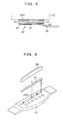
transducer 51 made of a piezoelectric device which is a long, narrow piece is disposed under asaddle 52. Concretely, thetransducer 51 and thesaddle 52 are sequentially put in asaddle slot 53A of abridge 53 mounted on a top of a not-shown body, so that thetransducer 51 is sandwiched by thebridge 53 and thesaddle 52. - In the
conventional structure 2, a transducer including a piezoelectric device is in a plate form and is mounted on an outer surface of a body with an adhesive or the like. - In the
conventional structure 3, a transducer includes a coil positioned inside a sound hole and is capable of transducing the vibration of strings into an electric signal by electromagnetic induction of the coil. - In the above-described conventional structure 1, however, since tension of strings gives a downward force to the
saddle 52, a relatively strong compressive force constantly acts on thetransducer 51. This obstructs free movement of thetransducer 51 itself, so that there is a tendency that the complicated vibration of the top caused by performance cannot be thoroughly transduced. This results in a problem that sound reproduced via an amplifier or the like has sound quality and tone quite different from actual performance sound that is directly heard from an acoustic guitar and reproducibility of the performance sound is thus impaired. - Further, in the
conventional structure 2, though the transducer senses the vibration of the body, the sensed vibration greatly varies depending on which position of the body it is mounted. Therefore, the work of adjusting the mounting position of the transducer in order to obtain good sound quality and tone becomes difficult and complicated, and theconventional structure 2 thus has a problem of an increased load required for this work. - On the other hand, in the
conventional structure 3, since the vibration of a body is not sensed, produced sound is different in sound quality and tone from performance sound that is heard when the transducer is not used. That is, since performance sound heard when the acoustic guitar is played is sound produced by the vibration mainly of a top of the body, theconventional structure 3 sensing mainly the vibration of strings has a problem of insufficient reproducibility. - Further, as a transducer such as a pickup capable of transducing the vibration of strings into an electric signal in a plucked string instrument such as an acoustic guitar as described above, known is that of a type provided with a plate-formed or a sheet-formed piezoelectric device. This piezoelectric device is mounted on a body of a stringed musical instrument via an adhesive layer made of rubber and is connected to an amplifier or the like via a lead wire. Therefore, the vibration of the strings when the stringed musical instrument is played propagates to the body, the adhesive layer, and the piezoelectric device in this order, and electric sound can be reproduced according to an electric signal outputted by the piezoelectric device.
- However, in this structure, though the adhesive layer attenuates the vibration of the strings before it propagates to the piezoelectric device, it is difficult to obtain a sufficient attenuating operation only with the adhesive layer, and when the string is plucked with a force which is not very strong, electric output level of the piezoelectric device sometimes reaches the maximum. Consequently, even plucking with a stronger force does not increase the output level and causes almost no change of the output level, which causes a problem that tone and quality of reproduced sound are not satisfactory enough.
- Moreover, there is a tendency that a frequency band in which a good attenuating operation is exhibited becomes relatively narrow, so that it becomes difficult to obtain a sufficient attenuating operation in a frequency band requiring the attenuation. As a result, for example, in a case where the adhesive layer exhibits a less sufficient attenuating operation in a mid/low register than in a high register, the output level unnaturally differs between these registers, which also causes deterioration of sound quality and tone.
- The invention was made to solve the above-described problems, and its object is to provide a stringed musical instrument, a transducer for the same, and its mounting structure on the same which can reduce workload required for adjustment and the like and make sound reproduced via the transducer as close to sound directly heard from the stringed musical instrument as possible.
- In order to achieve the object stated above, the invention adopts the following structure for a stringed musical instrument including: a plurality of strings arranged in parallel; a hollow body including a top and a back; a saddle supporting one end side areas of the strings; a bridge provided on a front surface of the top to support the saddle; and at least one transducer transducing vibration of the strings into an electric signal.
- The transducer has a mounting surface attached to face a back surface of the top of the body and the mounting surface is disposed in an area in the top, including an area right under an area where the bridge is provided.
- Preferably, the body has a reinforcing member provided in an area under the bridge in the back surface of the top, and the mounting surface of the transducer is attached to the reinforcing member.
- Preferably, pitches of the plural strings gradually change along an arrangement direction of the strings, the transducer is provided in plurality, and the mounting surfaces of the transducers are disposed in an area including an area substantially right under the saddle and in areas apart to both sides in the arrangement direction from an area right under the strings, respectively.
- In these stringed musical instruments, the transducer can be disposed in plurality in the area including the area substantially right under the saddle.
- In the above stringed musical instrument, preferably, the transducer includes: an adhesive layer forming the mounting surface; a piezoelectric device mounted on the body or the reinforcing member via the adhesive layer; and at least one intermediate layer provided in a thickness-wise middle portion of the adhesive layer and made of a material different from a material of the adhesive layer.
- A mounting structure of a transducer according to the invention is a mounting structure for mounting a transducer on a stringed musical instrument, the stringed musical instrument including: a hollow body including a top and a back; a bridge provided on a front surface of the top to support a saddle; and a plurality of strings supported by the saddle and arranged in parallel, and the transducer transducing vibration of the strings into an electric signal, wherein the transducer has a mounting surface attached to face a back surface of the top of the body, and the mounting surface is disposed in an area in the top, including an area right under an area where the bridge is provided.
- Preferably, the body has a reinforcing member in an area under the bridge in the back surface of the top, and the mounting surface of the transducer is attached to the reinforcing member.
- In the these mounting structures of the transducer, preferably, the transducer includes: an adhesive layer forming the mounting surface; a piezoelectric device mounted on the body or the reinforcing member via the adhesive layer; and at least one intermediate layer provided in a thickness-wise middle portion of the adhesive layer and made of a material different from a material of the adhesive layer.
- A transducer according to the invention is a transducer mounted on a body of a stringed musical instrument to transduce vibration of strings into an electric signal, the transducer including: a piezoelectric device mounted on the body via an adhesive layer; and at least one intermediate layer provided in a thickness-wise middle portion of the adhesive layer and made of a material different from a material of the adhesive layer.
- Preferably, the adhesive layer in the transducer is formed of butyl rubber, and the intermediate layer is formed of wood.
- According to the invention, the mounting surface of the transducer is positioned on the back surface side of the top of the body. Therefore, when a piezoelectric device in a sheet form or a thin plate form is used in the transducer, preload due to tension of the strings is not given to the transducer, so that the vibration of the top is transmitted as it is to the transducer. Consequently, sound reproduced via the transducer becomes similar to performance sound directly heard from the stringed musical instrument, which realizes enhanced reproducibility of the performance sound.
- Further, the mounting surface of the transducer is positioned in the area in the top, including the area right under the area where the bridge is provided. Therefore, the vibration propagating to the transducer is less susceptible to the structural influence of braces and the like of the top, which can stabilize quality of reproduced sound.
- In addition, since the transducer is not exposed on an outer side of the body, the transducer does not become an obstacle and can be kept mounted constantly, which can lighten a load of adjustment work and the like required in mounting the transducer.
- Further, if the mounting surface of the transducer is attached to the reinforcing member, the transducer transduces the vibration of an area, in the body, which vibrates relatively stably, so that acoustic feedback can be prevented, realizing further improved quality of reproduced sound.
- Further, if the mounting surfaces of the transducers are disposed in the area including the area substantially right under the saddle and in the areas apart to both sides in the arrangement direction of the strings from the area right under the strings, the aforesaid reproducibility can be further improved.
- Specifically, since the saddle supports the strings, the top in the area right under the saddle is easily excited in substantially parallel to the thickness direction by the vibration of the strings. Accordingly, the electric signal resulting from the transduce in an area including this area becomes reproduced sound close to fundamental tone of sound produced by the vibration of the strings. On the other hand, the electric signal resulting from the transduce on a side of the string producing the highest-pitch sound becomes reproduced sound relatively close to sound produced by air vibration caused by the vibration of the strings. The electric signal resulting from the transduce on a side of the string producing the lowest-pitch sound becomes reproduced sound relatively close to sound produced by the vibration of the top of the body.
- In this manner, various types of vibrations can be transduced into the electric signals, and reproduced sound based on the electric signals can be made closer to directly heard natural sound. Moreover, it is also possible to adjust a volume ratio of the electric signals from the respective transducers, via a mixing device or the like, which can facilitate the setting of variety of tones.
- Further, when the plural transducers are disposed in the area including the area substantially right under the saddle, for example, transducers transducing mainly the vibration of the high-pitch side strings and transducers transducing mainly the vibration of the low-pitch side strings can be provided separately. This makes it possible to more stably sense the vibrations of the respective strings, realizing further improved sound quality.
- The transducer according to the invention can provide the attenuation effect by the intermediate layer different from the attenuation effect by the adhesive layer, so that the vibration propagating to the piezoelectric device when a string is strongly plucked can be well attenuated. This can lower the output level of the piezoelectric device, so that the output level in accordance with a plucking force can be realized, which makes it possible to improve tone and quality of sound that is reproduced via an electric circuit part and a sound system.
- Further, the intermediate layer and the adhesive layer can be designed so that they exhibit the attenuating operations in different frequency bands each other, which makes it possible to expand a frequency band in which a good attenuating operation can be obtained.
- Therefore, a change in the output level due to difference in frequency band becomes small, which can also realize improved tone and quality of reproduced sound.
- Moreover, if a plurality of types of transducers whose intermediate layers are made of different materials are prepared, it is possible to obtain various kinds of attenuating operations only by changing these transducers, which can facilitate adjusting tone and the like.
- Note that in this specification and claims, "upper", "lower", and "left", "right" are used based on FIG. 4, unless otherwise noted. Further, "front" means the upper side in FIG. 3 and "back" means the lower side opposite the upper side.
- The above and other object, features and advantages of the invention will be apparent from the following detailed description which is to be read in conjunction with the accompanying drawings.
-
- FIG. 1 is a side view showing one embodiment of a stringed musical instrument according to the invention;
- FIG. 2 is a plane view seen from an upper side in FIG. 1;
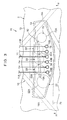
- FIG. 3 is a rough plane view showing an enlarged essential portion of the stringed musical instrument shown in FIG. 1 and FIG. 2 and a mounting structure of a transducer;
- FIG. 4 is a cross sectional view taken along the IV-IV line in FIG. 3, with part of the structure omitted;
- FIG. 5 is a cross sectional view showing a layered structure of the transducer shown in FIG. 3 and FIG. 4; and
- FIG. 6 is an exploded perspective view showing an example of a mounting structure of a transducer in a conventional stringed musical instrument.
- Hereinafter, preferred embodiments of the invention will be described with reference to the drawings. First, the external appearance of one embodiment of a stringed musical instrument according to the invention will be described with reference to FIG. 1 and FIG. 2. FIG. 1 is a side view of the stringed musical instrument and FIG. 2 is a plane view seen from an upper side in FIG. 1.
- A stringed
musical instrument 10 of this embodiment has substantially the same structure as that of an acoustic guitar which is a typical plucked string instrument. Abody 2 being an instrument main body of the stringedmusical instrument 10 has a top 15 and a back 16 whose outer peripheries are the same in shape, and thebody 2 is a hollow resonance body with the outer peripheries of the top 15 and the back 16 being bonded via acurved side panel 17. Acircular sound hole 14 is formed in a center portion of a smaller bulging portion of the top 15. - A
neck 3 supporting afingerboard 4 and having ahead 5 at an end portion thereof is fixed to an end portion of the right side of thebody 2 in FIG. 1 and FIG. 2. Further, on an opposite side (left side in FIG. 1) of thefingerboard 4 across thesound hole 14, abridge 13 supporting asaddle 12 is adhesively fixed on afront surface 15a of the top 15. - Six
tuning keys 7 geared torespective pegs 9 to rotate are provided in thehead 5 at the end portion of theneck 3, and between the tuningkeys 7 and pins 18 inserted in six through holes formed in thebridge 13, sixstrings 11 made of steel, gut, or the like are stretched. Anut 8, which is provided on a boundary of thehead 5 and theneck 3, and thesaddle 12, which is supported by thebridge 13, support thestrings 11 to give tension thereto. - Next, a part in this stringed musical instrument relating to the invention will be described in detail with reference to FIG. 3 to FIG. 5.
- FIG. 3 is a rough plane view showing an enlarged essential portion of the stringed musical instrument shown in FIG. 1 and FIG. 2 and a mounting structure of a transducer, and FIG. 4 shows a cross sectional view taken along the IV-IV line in FIG. 3, with part of the structure omitted.
- In the stringed
musical instrument 10 shown in these drawings, thestrings 11 are set so that pitches thereof gradually change to a higher side in their arrangement direction, namely, from the left to right direction. Here, among thestrings 11, the left-end string is astring 11A producing the lowest-pitch sound (hereinafter, referred to as the lowest-pitch string 11A), and the right-end string is astring 11B producing the highest-pitch sound (hereinafter, referred to as the highest-pitch string 11B). - The
saddle 12 stands on thebridge 13 to extend in the right and left direction, and an upper edge thereof supports back end areas of thestrings 11 so as to bend thestrings 11. The length of thesaddle 12 in the arrangement direction of thestrings 11 is set so that both ends thereof are positioned outside the lowest-pitch string 11A and the highest-pitch string 11B. - The
bridge 13 is made of, for example, ebony and has a plate shape along thefront surface 15a of the top 15, though this is not restrictive. Thebridge 13 gets gradually thinner toward a part thereof more distant from thesaddle 12, and asaddle slot 13A receiving thesaddle 12 is formed on an upper face side of thebridge 13. Further, thebridge 13 has at the back of thesaddle 12 sixholes 13B to which thepins 18 are inserted, and thepins 18 support the back end sides of thestrings 11. - The
bridge 13 is fixed with an adhesive or the like on thefront surface 15a of the top 15 of thebody 2. A plurality ofbraces 19 for reinforcing the top 15 are attached to aback surface 15b side of the top 15. Twobraces braces 19 are provided to extend in intersecting directions between thebridge 13 and thesound hole 14 shown in FIG. 2. - Further, a plate-shaped reinforcing
member 20 is provided in an area between the twobraces bridge 13 on theback surface 15b side of the top 15, and the reinforcingmember 20 reinforces an area, in the top 15, where thebridge 13 is mounted and to which load is given by the tension of thestrings 11. - On a lower face of the reinforcing
member 20, a plurality oftransducers 22 capable of transducing vibration of thestrings 11 into electric signals are provided. - Each of the
transducers 22 is formed in a plate form or a sheet form having a substantially circular shape when seen from above. An upper face of each of thetransducers 22 is a mountingsurface 22A attached to the lower face of the reinforcingmember 20 and faces theback surface 15b of the top 15. The mounting surfaces 22A are respectively arranged in an area including an area right under an area, in the top 15, where thebridge 13 is disposed, and concretely, are arranged so as to hardly run off the edge of the installation area of thebridge 13 in the state in FIG. 3 showing a plane view of thebridge 13. - Three of the
transducers 22 are provided under thesaddle 12, while the other two of them are provided at a position apart in the left direction from the lowest-pitch string 11A and at a position apart in the right direction from the highest-pitch string 11B, respectively. The mounting surfaces 22A of therespective transducers 22 under thesaddle 12 are disposed in an area including an area substantially right under thesaddle 12, and center portions of these surfaces are positioned between the lowest-pitch string 11A and itsadjacent string 11, between the highest-pitch string 11B and itsadjacent string 11, and between the two center strings, respectively. - The mounting
surface 22A of thetransducer 22 on the left side of the lowest-pitch string 11A is disposed between the lowest-pitch string 11A and thebrace 19A overlapping with a left end side of thebridge 13. On the other hand, the mountingsurface 22A of thetransducer 22 on the right side of the highest-pitch string 11B is disposed between the highest-pitch string 11B and thebrace 19A overlapping with the right end side of thebridge 13. - Each of the
transducers 22 has a layered structure as shown in FIG. 5. Specifically, it includes anadhesive layer 24 bonded to the lower face of the reinforcingmember 20, anintermediate layer 25 provided in a thickness-wise middle portion of theadhesive layer 24, and apiezoelectric device 27 in a sheet form or a plate form mounted on a lower face of theadhesive layer 24 via ametal plate 26 made of brass or the like. - The
adhesive layer 24 is made of, for example, butyl rubber. Butyl rubber comes in various kinds depending on composition, and this butyl rubber is preferably non-vulcanized and autohesive. Theintermediate layer 25 is made of a material different from the material of theadhesive layer 24, and in this embodiment, wood such as maple is used. Aground wire 29 is connected to themetal plate 26, and alead wire 30 is connected to thepiezoelectric device 27. - The
piezoelectric device 27 senses the vibration of the top 15 caused by the vibration of the pluckedstrings 11, transduces the vibration into an electric signal, and outputs the electric signal to an electric circuit part in thebody 2 via thelead wire 30. The electric circuit part is capable of amplifying and impedance-converting the electric signal outputted from each of thetransducers 22 by an operational amplifier and so on to output it to a sound system (an amplifier, a speaker, and so on) provided outside the stringedmusical instrument 10, via a mixing circuit, an equalizing circuit, and so on. - In the sound system, the electric signal inputted from the stringed
musical instrument 10 is amplified by the amplifier and electroacoustically transduced by the speaker to be outputted as performance sound. - In the above-described structure, as a result of plucking for playing the stringed
musical instrument 10, the vibration of thestrings 11 propagates to thesaddle 12, thebridge 13, the top 15, and each of thetransducers 22 in sequence to be transduced into the electric signal by each of thetransducers 22. The electric signal resulting from the transduce in each of thetransducers 22 is outputted to the aforesaid electric circuit part via thelead wire 30 and further reproduced as sound by the external sound system. - Here, the vibration of the top 15 propagating to each of the
transducers 22 differs depending on the thickness of thebridge 13 and the positional relation with the eachstring 11, and reproduced sound also differs accordingly. - To be in more detail, as for the area of the top 15 under the
saddle 12, the thickness of thebridge 13 in an area right thereabove is large and the distance to thesaddle 12 which becomes an excitation portion by supporting thestrings 11 is short, so that this area of the top 15 is easy to vibrate, being displaced substantially in parallel to the thickness direction. Therefore, each of thetransducers 22 under thesaddle 12 is capable of stably sensing and reproducing tone close to fundamental tone of the vibration of thestrings 11. - Further, as for areas of the top 15 on the right and left sides of the
saddle 12, the thickness of thebridge 13 in areas right thereabove is small, so that thebridge 13 in these areas is less stronger than in the area under thesaddle 12, but since the strength increases as the distance to thebraces transducer 22 on the left side of the lowest-pitch string 11A increases a harmonic component, and since it is close to the lowest-pitch string 11A, it is capable of stably sensing and reproducing tone close to sound that is directly heard when the top 15 vibrates. - The
transducer 22 on the right side of the highest-pitch string 11B also increases a harmonic component, and since it is close to the highest-pitch string 11B, it is capable of stably sensing and reproducing tone similar to sound produced by the vibration of air caused by the vibration of thestrings 11. - Since it is thus possible to sense the vibrations whose tone differs depending on the mounting positions of the
transducers 22, it is possible to set tone according to variety of music scenes by arbitrarily mixing and adjusting the electric signals outputted from therespective transducers 22, by the aforesaid mixing circuit of the electric circuit part. - For example, when a volume ratio is set as A : B : C = 2 : 3: 5, where A is volume of the
respective transducers 22 under thesaddle 12, B is volume of thetransducer 22 on the left side of the lowest-pitch string 11A, and C is volume of thetransducer 22 on the right side of the highest-pitch string 11B, the resultant sound is expected to have tone emphasizing sound of the stringedmusical instrument 10 in solo, and when the volume ratio is set as A : B : C = 3 : 2 : 5, the resultant sound is expected to have articulate tone emphasizing chord performance. - Incidentally, in each of the
transducers 22, the vibration propagating to thepiezoelectric device 27 from the mountingsurface 22A is attenuated by theadhesive layer 24 and theintermediate layer 25. In particular, theintermediate layer 25 made of maple is excited to consume vibration energy, so that it is capable of lowering the output level of thepiezoelectric device 27 to a predetermined value or lower. Consequently, it can be avoided that even an increased plucking force cannot change the output level, as is the case in the conventional structure, so that it is possible to improve tone and quality of reproduced sound. - Further, the
adhesive layer 24 made of butyl rubber can effectively exhibit the attenuating operation in a high register, which makes it possible to obtain clear tone with unnecessary reverberation eliminated. On the other hand, theintermediate layer 25 can exhibit an attenuating operation in frequency bands different from that in which theadhesive layer 24 exhibits the attenuating operation, namely, in a low register and a mid register, and can also provide an attenuation characteristic that butyl rubber does not have and that is unique to maple, and a tone correction effect. Therefore, it is possible to expand the frequency band where a good attenuating operation is obtainable by theintermediate layer 25 and to reduce or adjust unnecessary frequency components, which also makes it possible to realize better tone and sound quality. - Further, according to this embodiment, since the
respective transducers 22 are mounted on the reinforcingmember 20 positioned right under thesaddle 12, the vibration of the stably vibrating area in the top 15 can be picked up, so that it is possible to prevent the occurrence of acoustic feedback and thus maintain good quality and tone of electrically reproduced sound. Further, owing to the attenuation of the vibration by theintermediate layer 25, the electric signal outputted to the electric circuit part can be changed according to a plucking force. - Further, since the
respective transducers 22 are mounted on the lower face of the reinforcingmember 20 inside thebody 2, thetransducers 22 do not become obstacles even if this mounting state is constantly kept. This eliminates a need for mounting/dismounting thetransducers 22 and adjusting the outputs from thetransducers 22 every time the stringedmusical instrument 10 is put into and taken out of a case. - Moreover, providing the three
transducers 22 substantially right under thesaddle 12 can prevent volume difference among the strings, realizing improved sound quality. - The foregoing description has disclosed the best structure, method, and so on for carrying out the invention, but the present invention is not limited thereto.
- Therefore, though the specific embodiment of the invention is shown in the drawings and described, the shapes, positions, materials, directions, or other detailed structures of the embodiment described above can be modified in various ways by those skilled in the art without departing from the technical idea and scope of the object of the invention.
- Therefore, the above-disclosed description limiting the shape and so on are only given as an example for easy understanding of the invention and does not limit the invention. Therefore, description in the names of members without part or all of the restrictions of the shapes and so on are also included in the invention.
- For example, in the stringed musical instrument and the mounting structure of its transducer, other possible structure is to attach the mounting
surfaces 22A of therespective transducers 22 directly to the back surface of the top 15 without providing the reinforcingmember 20, or to provide only onetransducer 22 under thesaddle 12. However, in view of obtaining the aforesaid operations and effects, it is more preferable to provide the reinforcingmember 20 and dispose theplural transducers 22 as in the above-described embodiment. - Further, the number of the
transducers 22 installed under thesaddle 12 may be changed, and may be, for example six or two. When the number of thetransducers 22 is six, the center portions of their surfaces are preferably positioned substantially right under therespective strings 11, and when the number of thetransducers 22 is two, the center portions of their surfaces are preferably positioned substantially right under thestrings 11 adjacent to the lowest-pitch string 11A and the highest-pitch string 11B, respectively. - Further, the invention is applicable also to various kinds of other stringed musical instruments such as a classic guitar, a ukulele, a mandolin, and the like.
- The mounting positions of the
transducers 22 according to the invention can be changed in various ways, and for example, thetransducers 22 may be mounted on outer surfaces or the like of the top 15 or theback 16 of thebody 2. Further, the material of theintermediate layer 25 provided in the middle of theadhesive layer 24 is not limited to maple and various materials such as other wood may be used. - Therefore, by preparing a plurality of types of the
transducers 22 whose intermediate layers are made of different materials and changing thetransducers 22, it becomes possible to obtain different attenuation characteristics and tones ascribable to the materials of theintermediate layer 25, which can facilitate adjusting and correcting the tone. - Moreover, the
intermediate layer 25 may be formed in plurality, and in this case, theadhesive layer 24 is further interposed between the respective intermediate layers. Further, the planar size of theintermediate layer 25 may be smaller than that of theadhesive layer 24, or theintermediate layer 25 smaller than theadhesive layer 24 may be arranged in plurality in the same plane.
Claims (10)
- A stringed musical instrument comprising:a plurality of strings (11) arranged in parallel; a hollow body (2) including a top (15) and a back (16); a saddle (12) supporting one end side areas of the strings (11); a bridge (13) provided on a front surface of the top (15) to support the saddle (12); and at least one transducer (22) transducing vibration of the strings (11) into an electric signal,wherein said transducer (22) has a mounting surface (22A) attached to face a back surface (15b) of the top (15) of said body (2) and the mounting surface (22A) is disposed in an area in the top (15), including an area right under an area where said bridge (13) is provided.
- A stringed musical instrument according to claim 1, wherein said body (2) has a reinforcing member (20) in an area under said bridge (13) in the back surface (15b) of the top (15), and the mounting surface (22A) of said transducer (22) is attached to the reinforcing member (20).
- A stringed musical instrument according to claim 1, wherein pitches of said plural strings (11) gradually change along an arrangement direction of said strings (11), said transducer (22) is provided in plurality, and the mounting surfaces (22A) of said transducers (22) are disposed in an area including an area substantially right under said saddle (12) and in areas apart to both sides in the arrangement direction from an area right under said strings (11), respectively.
- A stringed musical instrument according to claim 3, wherein said transducer (22) is disposed in plurality in the area including the area substantially right under said saddle (12).
- A stringed musical instrument according to claim 1 or 2, wherein said transducer (22) includes: an adhesive layer (24) forming the mounting surface (22A); a piezoelectric device (27) mounted on said body (2) via the adhesive layer (24); and at least one intermediate layer (25) provided in a thickness-wise middle portion of the adhesive layer (24) and made of a material different from a material of the adhesive layer (24).
- A mounting structure of a transducer for mounting a transducer (22) on a stringed musical instrument (10), the stringed musical instrument (10) including: a hollow body (2) including a top (15) and a back (16); a bridge (13) provided on a front surface (15a) of the top (15) to support a saddle (12); and a plurality of strings (11) supported by the saddle (12) and arranged in parallel, and the transducer (22) transducing vibration of the strings (11) into an electric signal,
wherein said transducer (22) has a mounting surface (22A) attached to face a back surface (15b) of the top (15) of said body (2), and the mounting surface (22A) is disposed in an area in the top (15), including an area right under an area where said bridge (13) is provided. - A mounting structure of the transducer according to claim 6, wherein said body (2) has a reinforcing member (20) in an area under said bridge (13) in the front surface (15a) of the top (15), and the mounting surface (22A) of said transducer (22) is attached to the reinforcing member (20).
- A mounting structure of the transducer according to claim 6 or 7, wherein said transducer (22) includes: an adhesive layer (24) forming the mounting surface (22A); a piezoelectric device (27) mounted on said body (2) via the adhesive layer (24); and at least one intermediate layer (25) provided in a thickness-wise middle portion of the adhesive layer (24) and made of a material different from a material of the adhesive layer (24).
- A transducer mounted on a body of a stringed musical instrument to transduce vibration of strings into an electric signal, the transducer comprising:a piezoelectric device (27) mounted on said body (2) via an adhesive layer (24); and at least one intermediate layer (25) provided in a thickness-wise middle portion of the adhesive layer (24) and made of a material different from a material of the adhesive layer (24).
- A transducer according to claim 9, wherein said adhesive layer (24) is made of butyl rubber and said intermediate layer (25) is made of wood.
Applications Claiming Priority (2)
| Application Number | Priority Date | Filing Date | Title |
|---|---|---|---|
| JP2005131425A JP2006308870A (en) | 2005-04-28 | 2005-04-28 | Stringed instrument, and fitting structure for transducing device used therefor |
| JP2005131434A JP4281707B2 (en) | 2005-04-28 | 2005-04-28 | Conversion device and stringed instrument using the same |
Publications (2)
| Publication Number | Publication Date |
|---|---|
| EP1717795A1 true EP1717795A1 (en) | 2006-11-02 |
| EP1717795B1 EP1717795B1 (en) | 2007-11-07 |
Family
ID=36581717
Family Applications (1)
| Application Number | Title | Priority Date | Filing Date |
|---|---|---|---|
| EP06008772A Expired - Lifetime EP1717795B1 (en) | 2005-04-28 | 2006-04-27 | Transducer for stringed musical instrument |
Country Status (8)
| Country | Link |
|---|---|
| US (2) | US20060243121A1 (en) |
| EP (1) | EP1717795B1 (en) |
| KR (1) | KR100765656B1 (en) |
| AT (1) | ATE377820T1 (en) |
| CA (1) | CA2544984C (en) |
| DE (1) | DE602006000211T2 (en) |
| ES (1) | ES2294753T3 (en) |
| TW (1) | TWI298482B (en) |
Cited By (4)
| Publication number | Priority date | Publication date | Assignee | Title |
|---|---|---|---|---|
| WO2010053855A3 (en) * | 2008-11-07 | 2010-08-12 | Richard Barbera | Transducer saddle for stringed instrument |
| US8263851B2 (en) | 2008-11-07 | 2012-09-11 | Richard Barbera | Transducer saddle for stringed instrument |
| WO2014058546A1 (en) * | 2012-10-09 | 2014-04-17 | Kesumo, Llc | Pickup and sustainer for stringed instruments |
| EP3567580A1 (en) * | 2018-05-10 | 2019-11-13 | Bradley Roy Clark | An electronic sensor device for detecting the vibration related to an amplification system within stringed musical instruments |
Families Citing this family (13)
| Publication number | Priority date | Publication date | Assignee | Title |
|---|---|---|---|---|
| US7259318B2 (en) * | 2004-03-16 | 2007-08-21 | Ilitch S. Chiliachki | Magnetic pickup device for a stringed musical instrument with large free shape low impedance coil for noise cancelation |
| TWI298482B (en) * | 2005-04-28 | 2008-07-01 | Yamaha Corp | Stringed musical instrument, transducer for the same and its mounting structure on the same |
| US20100218665A1 (en) * | 2005-08-30 | 2010-09-02 | Bradley Clark | Sensor for an acoustic instrument |
| US7663038B2 (en) * | 2008-02-14 | 2010-02-16 | Thomas M. Stadler | Integral saddle and bridge for stringed musical instruments |
| US8748724B1 (en) * | 2009-11-25 | 2014-06-10 | Michael G. Harmon | Apparatus and method for generating effects based on audio signal analysis |
| US8704075B2 (en) * | 2010-04-27 | 2014-04-22 | Angelo Gournis | Guitar pickup assembly |
| JP5929375B2 (en) * | 2011-03-24 | 2016-06-08 | ヤマハ株式会社 | Instrument vibration sensors, pickup saddles and instruments |
| JP5935401B2 (en) * | 2012-03-06 | 2016-06-15 | ヤマハ株式会社 | Signal processing equipment for stringed instruments |
| DE102014106071A1 (en) * | 2014-04-30 | 2015-11-05 | Christian Aschauer | Sound transducer, sound source with sound transducer and method for converting the sound of a sound source into electrical signals |
| US9466276B1 (en) * | 2015-06-12 | 2016-10-11 | Steven Martin Olson | Stringed musical instrument having a resonator assembly |
| TWI634544B (en) * | 2017-06-21 | 2018-09-01 | 范志明 | Brake device for electric and acoustic guitars |
| FR3079655B1 (en) * | 2018-04-03 | 2020-03-27 | Wild Customs | DEVICE FOR INTERCHANGING ELECTRIC OR ELECTRONIC SYSTEMS FOR CAPTATION OF VIBRATION OF THE STRINGS OF A MUSICAL INSTRUMENT |
| CN115132157B (en) * | 2021-03-24 | 2025-10-10 | 雅马哈株式会社 | String instruments and sound effects devices |
Citations (7)
| Publication number | Priority date | Publication date | Assignee | Title |
|---|---|---|---|---|
| US3668295A (en) * | 1971-03-31 | 1972-06-06 | Paul Daniel Broussard | Electromagnetic audio pickup for stringed musical instruments, with volume control means, and suitable for use with any type strings |
| US3733425A (en) * | 1971-11-08 | 1973-05-15 | K Chaki | Pick up device for stringed instrument |
| US4218951A (en) * | 1979-06-01 | 1980-08-26 | Willard Tressel | Stringed instrument |
| US4941389A (en) * | 1988-08-22 | 1990-07-17 | Wendler David C | Electronic pickup with mounting assembly for a hollow bodied musical instrument |
| US5078041A (en) * | 1990-06-04 | 1992-01-07 | Schmued Laurence C | Suspension bridge pickup for guitar |
| US6605771B1 (en) * | 2001-03-23 | 2003-08-12 | Lloyd R. Baggs | Pickup assembly for musical instrument |
| US6822156B1 (en) * | 2002-07-30 | 2004-11-23 | Arnold M Lazarus | Acoustic guitar under the saddle piezo pickup |
Family Cites Families (27)
| Publication number | Priority date | Publication date | Assignee | Title |
|---|---|---|---|---|
| DE2648956A1 (en) | 1976-10-28 | 1978-05-11 | Bosch Gmbh Robert | Diaphragm valve for multicylinder IC engine - has mounting plug with integral valve seat and support ring |
| JPS5845860B2 (en) | 1977-02-09 | 1983-10-13 | 三菱電機株式会社 | modulation circuit |
| US4378721A (en) * | 1978-07-20 | 1983-04-05 | Kabushiki Kaisha Kawai Seisakusho | Pickup apparatus for an electric string type instrument |
| JPS587196A (en) | 1981-07-06 | 1983-01-14 | 株式会社日立製作所 | Audio signal detection device |
| JPS5814190A (en) | 1981-07-18 | 1983-01-26 | 駒田 仁志 | Pickup mount construction for musical instrument with sound body |
| US4501186A (en) * | 1982-06-21 | 1985-02-26 | Nippon Gakki Seizo Kabushiki Kaisha | Pickup device for stringed musical instrument |
| GB2137007A (en) | 1983-03-17 | 1984-09-26 | Andrew Bond | Electric guitar |
| US5670733A (en) * | 1986-04-28 | 1997-09-23 | Fishman; Lawrence R. | Musical instrument transducer |
| US4785704A (en) * | 1986-06-19 | 1988-11-22 | Fishman Lawrence R | Musical instrument transducer |
| US5123325A (en) * | 1991-04-05 | 1992-06-23 | Turner Robert A | Film piezoelectric pickup for stringed musical instruments |
| US5438157A (en) * | 1993-01-14 | 1995-08-01 | Actodyne General, Inc. | Acoustic pick-up assembly for a stringed musical instrument |
| JPH07146685A (en) | 1993-11-24 | 1995-06-06 | M R C Du Pont Kk | Damping material |
| JPH0825312A (en) | 1994-07-11 | 1996-01-30 | Takamine Gakki Seisakusho:Kk | Acoustic material and manufacture thereof |
| US5552562A (en) * | 1994-08-29 | 1996-09-03 | Motorola, Inc. | Inertial acoustic pickup |
| JPH08110781A (en) | 1994-10-11 | 1996-04-30 | Hoshino Gakki Kk | Pickup structure for guitar |
| JP2850836B2 (en) | 1996-03-12 | 1999-01-27 | ヤマハ株式会社 | Electronic drum pad |
| US5900572A (en) * | 1996-07-15 | 1999-05-04 | Donald Dean Markley | Pliable pickup for stringed instrument |
| JPH10240239A (en) | 1997-02-27 | 1998-09-11 | Yamaha Corp | Fitting structure for pickup device of electronic stringed instrument |
| US6191350B1 (en) * | 1999-02-02 | 2001-02-20 | The Guitron Corporation | Electronic stringed musical instrument |
| US6605711B1 (en) * | 1999-11-15 | 2003-08-12 | Ludwig Institute For Cancer Research | NY-ESO-1 peptide derivatives, and uses thereof |
| US6689943B2 (en) * | 2001-01-17 | 2004-02-10 | Gibson Guitar Corp. | Acoustic guitar with integral pickup mount |
| DE60231176D1 (en) * | 2001-09-27 | 2009-04-02 | Yamaha Corp | Simple electronic musical instrument, player console and built-in signal processing system |
| JP4007048B2 (en) | 2002-04-24 | 2007-11-14 | ヤマハ株式会社 | Electronic percussion instrument |
| JP3815426B2 (en) * | 2002-11-28 | 2006-08-30 | ヤマハ株式会社 | Piezoelectric transducer for stringed instruments, strings and stringed instruments for stringed instruments |
| US20050087062A1 (en) * | 2003-10-23 | 2005-04-28 | Yamaya Kiyohiko | Method of processing sounds from stringed instrument and pickup device for the same |
| CN100390858C (en) | 2003-12-29 | 2008-05-28 | 孙心若 | A passive electric string instrument |
| TWI298482B (en) * | 2005-04-28 | 2008-07-01 | Yamaha Corp | Stringed musical instrument, transducer for the same and its mounting structure on the same |
-
2006
- 2006-04-21 TW TW095114221A patent/TWI298482B/en not_active IP Right Cessation
- 2006-04-27 CA CA002544984A patent/CA2544984C/en not_active Expired - Fee Related
- 2006-04-27 US US11/413,768 patent/US20060243121A1/en not_active Abandoned
- 2006-04-27 EP EP06008772A patent/EP1717795B1/en not_active Expired - Lifetime
- 2006-04-27 DE DE602006000211T patent/DE602006000211T2/en not_active Expired - Lifetime
- 2006-04-27 ES ES06008772T patent/ES2294753T3/en not_active Expired - Lifetime
- 2006-04-27 KR KR1020060037930A patent/KR100765656B1/en not_active Expired - Fee Related
- 2006-04-27 AT AT06008772T patent/ATE377820T1/en not_active IP Right Cessation
-
2007
- 2007-10-25 US US11/924,536 patent/US7982125B2/en active Active
Patent Citations (7)
| Publication number | Priority date | Publication date | Assignee | Title |
|---|---|---|---|---|
| US3668295A (en) * | 1971-03-31 | 1972-06-06 | Paul Daniel Broussard | Electromagnetic audio pickup for stringed musical instruments, with volume control means, and suitable for use with any type strings |
| US3733425A (en) * | 1971-11-08 | 1973-05-15 | K Chaki | Pick up device for stringed instrument |
| US4218951A (en) * | 1979-06-01 | 1980-08-26 | Willard Tressel | Stringed instrument |
| US4941389A (en) * | 1988-08-22 | 1990-07-17 | Wendler David C | Electronic pickup with mounting assembly for a hollow bodied musical instrument |
| US5078041A (en) * | 1990-06-04 | 1992-01-07 | Schmued Laurence C | Suspension bridge pickup for guitar |
| US6605771B1 (en) * | 2001-03-23 | 2003-08-12 | Lloyd R. Baggs | Pickup assembly for musical instrument |
| US6822156B1 (en) * | 2002-07-30 | 2004-11-23 | Arnold M Lazarus | Acoustic guitar under the saddle piezo pickup |
Cited By (6)
| Publication number | Priority date | Publication date | Assignee | Title |
|---|---|---|---|---|
| WO2010053855A3 (en) * | 2008-11-07 | 2010-08-12 | Richard Barbera | Transducer saddle for stringed instrument |
| US8049095B2 (en) | 2008-11-07 | 2011-11-01 | Richard Barbera | Transducer saddle for stringed instrument |
| US8263851B2 (en) | 2008-11-07 | 2012-09-11 | Richard Barbera | Transducer saddle for stringed instrument |
| WO2014058546A1 (en) * | 2012-10-09 | 2014-04-17 | Kesumo, Llc | Pickup and sustainer for stringed instruments |
| US9183823B2 (en) | 2012-10-09 | 2015-11-10 | Kesumo, Llc | Pickup and sustainer for stringed instruments |
| EP3567580A1 (en) * | 2018-05-10 | 2019-11-13 | Bradley Roy Clark | An electronic sensor device for detecting the vibration related to an amplification system within stringed musical instruments |
Also Published As
| Publication number | Publication date |
|---|---|
| HK1093256A1 (en) | 2007-02-23 |
| KR20060113475A (en) | 2006-11-02 |
| CA2544984C (en) | 2009-11-03 |
| TW200643893A (en) | 2006-12-16 |
| TWI298482B (en) | 2008-07-01 |
| US7982125B2 (en) | 2011-07-19 |
| EP1717795B1 (en) | 2007-11-07 |
| US20080092724A1 (en) | 2008-04-24 |
| ES2294753T3 (en) | 2008-04-01 |
| ATE377820T1 (en) | 2007-11-15 |
| DE602006000211D1 (en) | 2007-12-20 |
| DE602006000211T2 (en) | 2008-08-28 |
| KR100765656B1 (en) | 2007-10-10 |
| US20060243121A1 (en) | 2006-11-02 |
| CA2544984A1 (en) | 2006-10-28 |
Similar Documents
| Publication | Publication Date | Title |
|---|---|---|
| US7982125B2 (en) | Transducer and stringed musical instrument including the same | |
| US6610915B2 (en) | Soundboard of composite fibre material construction | |
| US5052269A (en) | Acoustic-electric guitar with interior neck extension | |
| US4228715A (en) | Strain-gauge sound pickup for string instrument | |
| US7394015B2 (en) | Pickup device for plucked string instrument and plucked string instrument | |
| JP7098219B1 (en) | Stringed instrument exciter and stringed instrument exciter system | |
| JP2566703B2 (en) | Stringed instrument | |
| WO2015098936A1 (en) | Vibration detection mechanism and vibration sensor unit | |
| CN1855221B (en) | Changer and stringed instrument equipped with the same | |
| WO2007075890A2 (en) | Stringed musical instrument having harmonic bridge | |
| US7166788B2 (en) | Stringed musical instrument | |
| US20080257130A1 (en) | Stringed instrument construction | |
| US10311837B1 (en) | Enhanced string instrument | |
| JP4577441B2 (en) | Conversion device | |
| WO2007025330A1 (en) | A sensor for an acoustic instrument | |
| US6031164A (en) | Mute acoustic stringed musical instrument having damping bridge | |
| US20060042455A1 (en) | Piezoelectric transducer for stringed musical instruments | |
| JP2018163332A (en) | Bridge and stringed instrument | |
| HK1093256B (en) | Transducer and stringed musical instrument installing the same | |
| JP4281707B2 (en) | Conversion device and stringed instrument using the same | |
| JP2010224570A (en) | Stringed instrument | |
| JP3843812B2 (en) | Bowed instrument | |
| JP4528280B2 (en) | Musical sound device and musical sound control method. | |
| Mathews | Pickups for the vibrations of violin and guitar strings using piezoelectric bimorphic bender elements | |
| JP2008268777A (en) | Musical sound device and production method and processing method of musical sound device |
Legal Events
| Date | Code | Title | Description |
|---|---|---|---|
| PUAI | Public reference made under article 153(3) epc to a published international application that has entered the european phase |
Free format text: ORIGINAL CODE: 0009012 |
|
| AK | Designated contracting states |
Kind code of ref document: A1 Designated state(s): AT BE BG CH CY CZ DE DK EE ES FI FR GB GR HU IE IS IT LI LT LU LV MC NL PL PT RO SE SI SK TR |
|
| AX | Request for extension of the european patent |
Extension state: AL BA HR MK YU |
|
| GRAP | Despatch of communication of intention to grant a patent |
Free format text: ORIGINAL CODE: EPIDOSNIGR1 |
|
| 17P | Request for examination filed |
Effective date: 20070502 |
|
| RIN1 | Information on inventor provided before grant (corrected) |
Inventor name: TAKABAYASHI, YOJIRO Inventor name: HORI, KENTA |
|
| RTI1 | Title (correction) |
Free format text: TRANSDUCER FOR STRINGED MUSICAL INSTRUMENT |
|
| RAP1 | Party data changed (applicant data changed or rights of an application transferred) |
Owner name: YAMAHA CORPORATION |
|
| AKX | Designation fees paid |
Designated state(s): AT BE BG CH CY CZ DE DK EE ES FI FR GB GR HU IE IS IT LI LT LU LV MC NL PL PT RO SE SI SK TR |
|
| RIN1 | Information on inventor provided before grant (corrected) |
Inventor name: HORI, KENTA Inventor name: TAKABAYASHI, YOJIRO |
|
| RAP1 | Party data changed (applicant data changed or rights of an application transferred) |
Owner name: YAMAHA CORPORATION |
|
| RIN1 | Information on inventor provided before grant (corrected) |
Inventor name: HORI, KENTA Inventor name: TAKABAYASHI, YOJIRO |
|
| GRAS | Grant fee paid |
Free format text: ORIGINAL CODE: EPIDOSNIGR3 |
|
| GRAA | (expected) grant |
Free format text: ORIGINAL CODE: 0009210 |
|
| AK | Designated contracting states |
Kind code of ref document: B1 Designated state(s): AT BE BG CH CY CZ DE DK EE ES FI FR GB GR HU IE IS IT LI LT LU LV MC NL PL PT RO SE SI SK TR |
|
| REG | Reference to a national code |
Ref country code: GB Ref legal event code: FG4D |
|
| REG | Reference to a national code |
Ref country code: IE Ref legal event code: FG4D |
|
| REG | Reference to a national code |
Ref country code: CH Ref legal event code: EP |
|
| REF | Corresponds to: |
Ref document number: 602006000211 Country of ref document: DE Date of ref document: 20071220 Kind code of ref document: P |
|
| REG | Reference to a national code |
Ref country code: SE Ref legal event code: TRGR |
|
| REG | Reference to a national code |
Ref country code: ES Ref legal event code: FG2A Ref document number: 2294753 Country of ref document: ES Kind code of ref document: T3 |
|
| PG25 | Lapsed in a contracting state [announced via postgrant information from national office to epo] |
Ref country code: NL Free format text: LAPSE BECAUSE OF FAILURE TO SUBMIT A TRANSLATION OF THE DESCRIPTION OR TO PAY THE FEE WITHIN THE PRESCRIBED TIME-LIMIT Effective date: 20071107 Ref country code: LI Free format text: LAPSE BECAUSE OF FAILURE TO SUBMIT A TRANSLATION OF THE DESCRIPTION OR TO PAY THE FEE WITHIN THE PRESCRIBED TIME-LIMIT Effective date: 20071107 Ref country code: CH Free format text: LAPSE BECAUSE OF FAILURE TO SUBMIT A TRANSLATION OF THE DESCRIPTION OR TO PAY THE FEE WITHIN THE PRESCRIBED TIME-LIMIT Effective date: 20071107 |
|
| NLV1 | Nl: lapsed or annulled due to failure to fulfill the requirements of art. 29p and 29m of the patents act | ||
| PG25 | Lapsed in a contracting state [announced via postgrant information from national office to epo] |
Ref country code: PL Free format text: LAPSE BECAUSE OF FAILURE TO SUBMIT A TRANSLATION OF THE DESCRIPTION OR TO PAY THE FEE WITHIN THE PRESCRIBED TIME-LIMIT Effective date: 20071107 Ref country code: IS Free format text: LAPSE BECAUSE OF FAILURE TO SUBMIT A TRANSLATION OF THE DESCRIPTION OR TO PAY THE FEE WITHIN THE PRESCRIBED TIME-LIMIT Effective date: 20080307 Ref country code: LT Free format text: LAPSE BECAUSE OF FAILURE TO SUBMIT A TRANSLATION OF THE DESCRIPTION OR TO PAY THE FEE WITHIN THE PRESCRIBED TIME-LIMIT Effective date: 20071107 Ref country code: LV Free format text: LAPSE BECAUSE OF FAILURE TO SUBMIT A TRANSLATION OF THE DESCRIPTION OR TO PAY THE FEE WITHIN THE PRESCRIBED TIME-LIMIT Effective date: 20071107 Ref country code: BG Free format text: LAPSE BECAUSE OF FAILURE TO SUBMIT A TRANSLATION OF THE DESCRIPTION OR TO PAY THE FEE WITHIN THE PRESCRIBED TIME-LIMIT Effective date: 20080207 Ref country code: SI Free format text: LAPSE BECAUSE OF FAILURE TO SUBMIT A TRANSLATION OF THE DESCRIPTION OR TO PAY THE FEE WITHIN THE PRESCRIBED TIME-LIMIT Effective date: 20071107 |
|
| REG | Reference to a national code |
Ref country code: CH Ref legal event code: PL |
|
| PG25 | Lapsed in a contracting state [announced via postgrant information from national office to epo] |
Ref country code: AT Free format text: LAPSE BECAUSE OF FAILURE TO SUBMIT A TRANSLATION OF THE DESCRIPTION OR TO PAY THE FEE WITHIN THE PRESCRIBED TIME-LIMIT Effective date: 20071107 |
|
| ET | Fr: translation filed | ||
| PG25 | Lapsed in a contracting state [announced via postgrant information from national office to epo] |
Ref country code: DK Free format text: LAPSE BECAUSE OF FAILURE TO SUBMIT A TRANSLATION OF THE DESCRIPTION OR TO PAY THE FEE WITHIN THE PRESCRIBED TIME-LIMIT Effective date: 20071107 Ref country code: CZ Free format text: LAPSE BECAUSE OF FAILURE TO SUBMIT A TRANSLATION OF THE DESCRIPTION OR TO PAY THE FEE WITHIN THE PRESCRIBED TIME-LIMIT Effective date: 20071107 |
|
| PG25 | Lapsed in a contracting state [announced via postgrant information from national office to epo] |
Ref country code: SK Free format text: LAPSE BECAUSE OF FAILURE TO SUBMIT A TRANSLATION OF THE DESCRIPTION OR TO PAY THE FEE WITHIN THE PRESCRIBED TIME-LIMIT Effective date: 20071107 Ref country code: RO Free format text: LAPSE BECAUSE OF FAILURE TO SUBMIT A TRANSLATION OF THE DESCRIPTION OR TO PAY THE FEE WITHIN THE PRESCRIBED TIME-LIMIT Effective date: 20071107 Ref country code: BE Free format text: LAPSE BECAUSE OF FAILURE TO SUBMIT A TRANSLATION OF THE DESCRIPTION OR TO PAY THE FEE WITHIN THE PRESCRIBED TIME-LIMIT Effective date: 20071107 |
|
| PLBE | No opposition filed within time limit |
Free format text: ORIGINAL CODE: 0009261 |
|
| STAA | Information on the status of an ep patent application or granted ep patent |
Free format text: STATUS: NO OPPOSITION FILED WITHIN TIME LIMIT |
|
| PG25 | Lapsed in a contracting state [announced via postgrant information from national office to epo] |
Ref country code: PT Free format text: LAPSE BECAUSE OF FAILURE TO SUBMIT A TRANSLATION OF THE DESCRIPTION OR TO PAY THE FEE WITHIN THE PRESCRIBED TIME-LIMIT Effective date: 20080407 |
|
| 26N | No opposition filed |
Effective date: 20080808 |
|
| PG25 | Lapsed in a contracting state [announced via postgrant information from national office to epo] |
Ref country code: MC Free format text: LAPSE BECAUSE OF NON-PAYMENT OF DUE FEES Effective date: 20080430 |
|
| PG25 | Lapsed in a contracting state [announced via postgrant information from national office to epo] |
Ref country code: GR Free format text: LAPSE BECAUSE OF FAILURE TO SUBMIT A TRANSLATION OF THE DESCRIPTION OR TO PAY THE FEE WITHIN THE PRESCRIBED TIME-LIMIT Effective date: 20080208 Ref country code: EE Free format text: LAPSE BECAUSE OF FAILURE TO SUBMIT A TRANSLATION OF THE DESCRIPTION OR TO PAY THE FEE WITHIN THE PRESCRIBED TIME-LIMIT Effective date: 20071107 |
|
| PG25 | Lapsed in a contracting state [announced via postgrant information from national office to epo] |
Ref country code: FI Free format text: LAPSE BECAUSE OF FAILURE TO SUBMIT A TRANSLATION OF THE DESCRIPTION OR TO PAY THE FEE WITHIN THE PRESCRIBED TIME-LIMIT Effective date: 20071107 |
|
| PG25 | Lapsed in a contracting state [announced via postgrant information from national office to epo] |
Ref country code: IE Free format text: LAPSE BECAUSE OF NON-PAYMENT OF DUE FEES Effective date: 20080428 |
|
| PG25 | Lapsed in a contracting state [announced via postgrant information from national office to epo] |
Ref country code: CY Free format text: LAPSE BECAUSE OF FAILURE TO SUBMIT A TRANSLATION OF THE DESCRIPTION OR TO PAY THE FEE WITHIN THE PRESCRIBED TIME-LIMIT Effective date: 20071107 |
|
| PG25 | Lapsed in a contracting state [announced via postgrant information from national office to epo] |
Ref country code: HU Free format text: LAPSE BECAUSE OF FAILURE TO SUBMIT A TRANSLATION OF THE DESCRIPTION OR TO PAY THE FEE WITHIN THE PRESCRIBED TIME-LIMIT Effective date: 20080508 Ref country code: LU Free format text: LAPSE BECAUSE OF NON-PAYMENT OF DUE FEES Effective date: 20080427 |
|
| PG25 | Lapsed in a contracting state [announced via postgrant information from national office to epo] |
Ref country code: TR Free format text: LAPSE BECAUSE OF FAILURE TO SUBMIT A TRANSLATION OF THE DESCRIPTION OR TO PAY THE FEE WITHIN THE PRESCRIBED TIME-LIMIT Effective date: 20071107 |
|
| REG | Reference to a national code |
Ref country code: FR Ref legal event code: PLFP Year of fee payment: 10 |
|
| REG | Reference to a national code |
Ref country code: FR Ref legal event code: PLFP Year of fee payment: 11 |
|
| REG | Reference to a national code |
Ref country code: FR Ref legal event code: PLFP Year of fee payment: 12 |
|
| REG | Reference to a national code |
Ref country code: FR Ref legal event code: PLFP Year of fee payment: 13 |
|
| PGFP | Annual fee paid to national office [announced via postgrant information from national office to epo] |
Ref country code: PL Payment date: 20190401 Year of fee payment: 10 Ref country code: IT Payment date: 20190429 Year of fee payment: 14 |
|
| PGFP | Annual fee paid to national office [announced via postgrant information from national office to epo] |
Ref country code: SE Payment date: 20190418 Year of fee payment: 14 |
|
| PG25 | Lapsed in a contracting state [announced via postgrant information from national office to epo] |
Ref country code: SE Free format text: LAPSE BECAUSE OF NON-PAYMENT OF DUE FEES Effective date: 20200428 |
|
| REG | Reference to a national code |
Ref country code: ES Ref legal event code: FD2A Effective date: 20210906 |
|
| PG25 | Lapsed in a contracting state [announced via postgrant information from national office to epo] |
Ref country code: ES Free format text: LAPSE BECAUSE OF NON-PAYMENT OF DUE FEES Effective date: 20200428 |
|
| PG25 | Lapsed in a contracting state [announced via postgrant information from national office to epo] |
Ref country code: IT Free format text: LAPSE BECAUSE OF NON-PAYMENT OF DUE FEES Effective date: 20200427 |
|
| PGFP | Annual fee paid to national office [announced via postgrant information from national office to epo] |
Ref country code: FR Payment date: 20230420 Year of fee payment: 18 Ref country code: DE Payment date: 20230420 Year of fee payment: 18 |
|
| PGFP | Annual fee paid to national office [announced via postgrant information from national office to epo] |
Ref country code: GB Payment date: 20230419 Year of fee payment: 18 |
|
| REG | Reference to a national code |
Ref country code: DE Ref legal event code: R119 Ref document number: 602006000211 Country of ref document: DE |
|
| GBPC | Gb: european patent ceased through non-payment of renewal fee |
Effective date: 20240427 |
|
| PG25 | Lapsed in a contracting state [announced via postgrant information from national office to epo] |
Ref country code: DE Free format text: LAPSE BECAUSE OF NON-PAYMENT OF DUE FEES Effective date: 20241105 |
|
| PG25 | Lapsed in a contracting state [announced via postgrant information from national office to epo] |
Ref country code: GB Free format text: LAPSE BECAUSE OF NON-PAYMENT OF DUE FEES Effective date: 20240427 |
|
| PG25 | Lapsed in a contracting state [announced via postgrant information from national office to epo] |
Ref country code: FR Free format text: LAPSE BECAUSE OF NON-PAYMENT OF DUE FEES Effective date: 20240430 |
|
| PG25 | Lapsed in a contracting state [announced via postgrant information from national office to epo] |
Ref country code: GB Free format text: LAPSE BECAUSE OF NON-PAYMENT OF DUE FEES Effective date: 20240427 Ref country code: FR Free format text: LAPSE BECAUSE OF NON-PAYMENT OF DUE FEES Effective date: 20240430 Ref country code: DE Free format text: LAPSE BECAUSE OF NON-PAYMENT OF DUE FEES Effective date: 20241105 |