EP1717564A1 - Will call wireless tank level monitoring system - Google Patents
Will call wireless tank level monitoring system Download PDFInfo
- Publication number
- EP1717564A1 EP1717564A1 EP20060008755 EP06008755A EP1717564A1 EP 1717564 A1 EP1717564 A1 EP 1717564A1 EP 20060008755 EP20060008755 EP 20060008755 EP 06008755 A EP06008755 A EP 06008755A EP 1717564 A1 EP1717564 A1 EP 1717564A1
- Authority
- EP
- European Patent Office
- Prior art keywords
- tank
- base station
- level
- tank level
- transmitter module
- Prior art date
- Legal status (The legal status is an assumption and is not a legal conclusion. Google has not performed a legal analysis and makes no representation as to the accuracy of the status listed.)
- Withdrawn
Links
- 238000012544 monitoring process Methods 0.000 title claims abstract description 13
- 230000000007 visual effect Effects 0.000 claims abstract description 9
- 238000000034 method Methods 0.000 claims description 7
- 238000004891 communication Methods 0.000 claims description 3
- 239000004973 liquid crystal related substance Substances 0.000 claims description 3
- 230000007958 sleep Effects 0.000 claims description 3
- 238000005286 illumination Methods 0.000 claims 1
- 239000007788 liquid Substances 0.000 abstract description 7
- 239000000446 fuel Substances 0.000 description 47
- 238000012384 transportation and delivery Methods 0.000 description 18
- ATUOYWHBWRKTHZ-UHFFFAOYSA-N Propane Chemical compound CCC ATUOYWHBWRKTHZ-UHFFFAOYSA-N 0.000 description 12
- 238000009434 installation Methods 0.000 description 7
- 230000005355 Hall effect Effects 0.000 description 6
- 230000005540 biological transmission Effects 0.000 description 6
- 239000001294 propane Substances 0.000 description 6
- 238000010411 cooking Methods 0.000 description 5
- 239000002828 fuel tank Substances 0.000 description 5
- 238000010438 heat treatment Methods 0.000 description 5
- 230000000737 periodic effect Effects 0.000 description 5
- 239000007789 gas Substances 0.000 description 4
- VNWKTOKETHGBQD-UHFFFAOYSA-N methane Chemical compound C VNWKTOKETHGBQD-UHFFFAOYSA-N 0.000 description 4
- 238000012986 modification Methods 0.000 description 2
- 230000004048 modification Effects 0.000 description 2
- 239000003345 natural gas Substances 0.000 description 2
- XLYOFNOQVPJJNP-UHFFFAOYSA-N water Substances O XLYOFNOQVPJJNP-UHFFFAOYSA-N 0.000 description 2
- 230000008878 coupling Effects 0.000 description 1
- 238000010168 coupling process Methods 0.000 description 1
- 238000005859 coupling reaction Methods 0.000 description 1
- 230000005611 electricity Effects 0.000 description 1
- 239000000295 fuel oil Substances 0.000 description 1
- 231100001261 hazardous Toxicity 0.000 description 1
- 239000000463 material Substances 0.000 description 1
- 238000005070 sampling Methods 0.000 description 1
- 230000001755 vocal effect Effects 0.000 description 1
- 230000002618 waking effect Effects 0.000 description 1
- 230000003442 weekly effect Effects 0.000 description 1
Images


Classifications
-
- G—PHYSICS
- G01—MEASURING; TESTING
- G01F—MEASURING VOLUME, VOLUME FLOW, MASS FLOW OR LIQUID LEVEL; METERING BY VOLUME
- G01F23/00—Indicating or measuring liquid level or level of fluent solid material, e.g. indicating in terms of volume or indicating by means of an alarm
- G01F23/14—Indicating or measuring liquid level or level of fluent solid material, e.g. indicating in terms of volume or indicating by means of an alarm by measurement of pressure
- G01F23/18—Indicating, recording or alarm devices actuated electrically
-
- G—PHYSICS
- G01—MEASURING; TESTING
- G01F—MEASURING VOLUME, VOLUME FLOW, MASS FLOW OR LIQUID LEVEL; METERING BY VOLUME
- G01F23/00—Indicating or measuring liquid level or level of fluent solid material, e.g. indicating in terms of volume or indicating by means of an alarm
- G01F23/80—Arrangements for signal processing
- G01F23/802—Particular electronic circuits for digital processing equipment
-
- Y—GENERAL TAGGING OF NEW TECHNOLOGICAL DEVELOPMENTS; GENERAL TAGGING OF CROSS-SECTIONAL TECHNOLOGIES SPANNING OVER SEVERAL SECTIONS OF THE IPC; TECHNICAL SUBJECTS COVERED BY FORMER USPC CROSS-REFERENCE ART COLLECTIONS [XRACs] AND DIGESTS
- Y10—TECHNICAL SUBJECTS COVERED BY FORMER USPC
- Y10T—TECHNICAL SUBJECTS COVERED BY FORMER US CLASSIFICATION
- Y10T137/00—Fluid handling
- Y10T137/8158—With indicator, register, recorder, alarm or inspection means
- Y10T137/8342—Liquid level responsive indicator, recorder or alarm
Definitions
- the present invention relates to tank level monitoring systems, and more particularly to wireless tank level monitoring systems for use with residential fuel tanks such as propane, water tanks, cisterns, etc.
- a rural customer contracts with the fuel company to make periodic deliveries to refuel the storage tank.
- periodic deliveries may be scheduled weekly, monthly, etc.
- deliveries are scheduled so that the customer will not have run out of fuel before the next scheduled delivery is made under an estimated maximum usage of the fuel by that customer.
- the rural customer pays a premium for such a service. This is because the rural customer often pays a fixed delivery charge regardless of the amount of fuel that is actually refilled into their storage tank.
- the rural user may actually need only a very small amount of fuel. Nonetheless, the user must pay the full delivery charge for having the fuel truck come to the installation.
- a second type of arrangement between the fuel company and the rural customer is known as a will call arrangement.
- the user has responsibility for monitoring the level of fuel remaining in the tank and calling the fuel company to schedule the next delivery to preclude the tank from running empty.
- the user is required to periodically check a gauge or dial installed on the storage tank to determine the amomt of fuel left in the tank.
- the rural customer contacts the fuel company to request a delivery of fuel to refill the storage tank.
- Many rural customers like this will call arrangement because it minimizes the fixed delivery cost as a proportion of the amount of fuel needed to refill the tank because a delivery is only requested when refilling is necessary.
- the present invention provides a new and improved tank level monitoring system that overcomes the above described and other problems existing in the art. More specifically, it is an objective of the present invention to provide a new improved wireless tank level monitoring system that may be used with residential fuel tank installations to provide remote indication of fuel tank level. As such, the wireless fuel tank level monitoring system alleviates the requirement that a user physically go to the storage tank to read the level gauge installed thereon.
- an embodiment of the wireless tank level monitoring system includes a transmitter module and a base station.
- the transmitter module is located at or on the fuel storage tank, and the base station is located within the user's dwelling or other convenient location easily accessible by the user.
- mounting of the transmitter module is accommodated by a plastic holster that may be installed on the storage tank, dome, lifting eye or gas line.
- the transmitter module uses a transducer that is coupled to a level sensing apparatus, such as a remote-ready tank level gauge, a Hall effect switch, a magneto-resistive sensor, etc.
- the transmitter module continuously reads the output from the sensing apparatus, e.g.
- the remote- ready level gauge, Hall effect switch, etc. transmits this information to the base station for display to the user.
- the transmitter sleeps, periodically waking to measure the level and transmit the reading to the base station.
- the base station includes a radio frequency (RF) receiver and a small liquid crystal display (LCD).
- the base station may receive power from the residential electrical system, or preferably is battery powered.
- Information regarding the level of fuel remaining in the storage tank is displayed on the LCD numerically in percent of full, graphically with a bar chart, or preferably both numerically and graphically.
- a visual warning is provided when the tank level drops below a predetermined set point.
- the numeric, bar chart, or combined information is flashed at a predetermined rate until such time as the fuel level increases above the predetermined set point.
- the base station also includes an indication of low battery condition for both the receiver and the base station.
- the transmitter module and the base station include transceiver circuitry to allow both transmission and reception of information and/or commands.
- the base station may transmit a request for tank level information.
- the transmitter module would then take a reading and transmit the tank level information to the base station. This feature could be in addition to or in place of the continuous and/or periodic reading and transmission of tank level information discussed above.
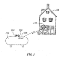
- FIG. 1 illustrates a simplified operating environment in which the wireless tank level monitoring system of the present invention finds particular applicability
- FIG. 2 is a front view of a transmitter module coupled to a remote-ready tank level gauge used in an embodiment of the present invention
- FIG. 3 is a rear view of the transmitter module of FIG. 2 illustrating a mounting holster for use therewith;
- FIG. 4 is a side view of the transmitter of FIG. 2;
- FIG. 5 is a top view of the transmitter of FIG. 2;
- FIG. 6 is an isometric illustration of an embodiment of a base station for use with the system of the present invention.
- FIG. 7 illustrates an alternate LCD layout for use in an alternate embodiment of the base station of the present invention.
- the system of the present invention will be described in an operating environment in which a rural residential customer utilizes liquid propane (LP) gas for heating, cooking, etc.
- the rural customer utilizes an above-ground LP gas storage tank 100 to store the propane that it utilizes to heat his residence 102, with which to cook food, etc.
- the LP storage tank 100 is located on the user's property at a location remote from the dwelling 102 for safety reasons.
- the particular type of fuel used by the residential customer is not limiting on the scope of the present invention.
- the tank level sensing system of the present invention may be applied to water level sensing in, e.g., a cistern.
- this operating environment is provided by way of illustration only, and not by way of limitation.
- different types of fuels and other liquids may require different types of fuel level sensing equipment, such equipment being well-known to those skilled in the art.
- the level of fuel remaining in the tank is displayed on a tank level gauge 104 that is installed on the fuel storage tank 100.
- this tank level gauge 104 is a remote-ready gauge that provides a ratiometric voltage output proportional to the liquid volume inside the tank.
- One such remote-ready tank level monitor gauge that may be utilized in an embodiment of the present invention is the Rochester Remote-Ready Dial, R 3 D, supplied by Rochester Gauges, Inc.
- This remote-ready dial includes a Hall effect module that is designed to snap-fit into a recess in the remote-ready dial lens. Once installed, the module can provide ratiometric voltage output proportional to the liquid volume inside the tank.
- a wireless transmitter module 106 that is coupled to the gauge 104 via wire 108 wirelessly transmits the tank level information to a base station module 110 that may be installed in the consumer's home 102, or other convenient location remote from the storage tank 100.
- This base station 110 displays the tank level information to the user so that the user may call to schedule a fuel delivery without having to hike to the remotely located storage tank 100.
- the wireless communication between the transmitter 106 and the base station 110 is accomplished at the 433 megahertz band using ASK modulation.
- the total link budget for the system is set such that the transmitter 106 and base station 110 can communicate over an open field line-of-sight distance of no less than 50 meters with the transmitter 106 and base station 110 at approximately 2 meters above the ground.
- other frequency bands and modulation techniques can be utilized depending on the requirements of a particular installation and the restrictions set forth by the FCC or other governing agency, as well as power consumption rates and physical location of the residence 102 and the storage tank 100.
- the transmitter module 106 is connected to the remote-ready gauge 104 via, in a preferred embodiment, a 1.5 meter long wire 108.
- This wire 108 is sealed at both ends for continuous outdoor operation.
- the transmitter 106 is also designed for continuous outdoor exposure and is preferably certified intrinsically safe for operation in hazardous classified locations with continuous presence of propane vapors.
- the transmitter 106 operates on battery power, preferably 2 AA batteries, with a battery life of 2 years minimum. In order to achieve this battery life from 2 AA batteries, the transmitter 106 wakes only briefly to read the output from the gauge 104 and to transmit that information to the base station 110.
- the duration of the period between reading and transmission cycles is set, in a preferred embodiment, at 90 seconds. However, this period may be adjusted based on consumer consumption rate of the fuel, etc.
- the longer the duration of the sleep period of the transmitter 106 the greater the change in the displayed tank level on the base station 110 when the update is transmitted.
- the sampling and transmission intervals should be relatively short compared to the rate at which fuel is consumed from the storage tank 100.
- a preferred embodiment of the transmitter of the present invention wakes briefly every 90 seconds to read and transmit the tank level information to the base station 110.
- the wire 108 must be suitable for continuous outdoor exposure, and preferably is sealed at both ends. To meet the operating requirements of a typical installation, this wire 108 is preferably a UL approved AWG 24 or larger gage wire.
- the transmitter 106 interfaces with the gauge 104 via a transducer, e.g. a temperature compensated Hall effect module 112.
- a magnetic coupling between the pointer magnet of the gauge 104 and the Hall effect module 112 is converted into an electrical signal that is read by the transmitter 106.
- This module 112 provides a ratiometric output that is converted within the transmitter 106 into a level reading that may be transmitted to the base station 110.
- other transducers may be used, e.g.
- the transmitter 106 adjusts for the orientation of the storage tank 100 in accordance with table 1 below.
- the setting of the tank orientation and the adjustment thereof may be done in the base station 110.
- a determination of the orientation of the fuel storage tank 100 may be made by selection of a selector switch 114.
- a holster 118 may be used to hold the transmitter module 106.
- This holster 118 may be made of plastic or other material, and may be mounded to the propane tank, dome, lifting eye, gas line, etc. as appropriate. Once mounted, the holster 118 removably secures the transmitter 106 therein.
- the base station 110 is a compact unit designed for indoor operation. While one embodiment of the base station 110 is powered from the electrical system within the dwelling 102, a preferred embodiment utilizes battery power, preferably 2 AAA batteries for power. In a preferred embodiment of the present invention, the base station 110 has a battery life of approximately 1.5 years minimum.
- the base station 110 includes an RF receiver and a small liquid crystal display (LCD) 116.
- the base station 110 can communicate with only one remote transmitter 106. In such an embodiment, if multiple tanks are to be monitored in a given location, then a separate base station 110 must be used for each tank.
- the base station may include a larger display capable of displaying multiple tank level indications, may simply provide the user with the ability to select different tanks being monitored, or may periodically scroll through the information for the different tanks.
- the level reading received from transmitter 106 is displayed on the base station LCD 116 numerically in percent full with a resolution of 1%. Additionally or alternatively, the LCD 116 may also include a graphic indication of the level reading utilizing, e.g., a bar chart at a resolution of 10%.
- the base station 110 provides a visual indication once the level of the tank drops below a predetermined set point, e.g. the 25% point. In one embodiment, both the bar chart and the numeric level reading will flash at a given rate, preferably 1 hertz, until such time as the level increases to above the 25% point. In embodiments having a backlit LCD, the backlighting may also be utilized to provide the visual indication either continuously, or flashing.
- the LCD 116 also includes an indication of low battery condition in embodiments utilizing battery power.
- a low battery icon is used, while in the configuration illustrated in FIG. 7 a "LOW BAT" verbal message is used.
- both an "IN” and an "OUT” icon are also utilized to designate the base station battery and the transmitter battery, respectively.
- the base station 110 displays the "OUT" icon along with the low battery icon. If, instead, the base station detects a low battery condition, it will display the "IN” icon and the low battery icon. In this way, the user is prompted to change the battery of either the transmitter or the base station as the case may be, In the event that both the transmitter and the base station have low batteries, all three of the icons will be activated.
- each segment of the bar chart can equate to approximately 10% of the tank level.
- all 10 segments will be displayed when the tank level is greater than or equal to 98% of the full capacity.
- Nine segments will be displayed when the tank level is greater than or equal to 90.
- An additional segment of the display will be removed for each 10% drop in fuel level until a single bar remains when the tank level is greater than or equal to 10%.
- no icons will be displayed in the graphic bar chart.
- a preferred embodiment will provide a visually conspicuous indication, e.g. flash the bar graph segments at a predetermined rate, when the level drops below the predetermined low tank level, e.g. 25%.
- the transmitter module 106 and the base station 110 include transceiver circuitry to allow both transmission and reception of information and/or commands.
- the base station 110 may transmit a request for tank level information.
- the transmitter module 106 would then take a reading and transmit the tank level information to the base station 110. This allows the user to obtain a current tank level reading on demand. Preferably, the current tank level is displayed for a short period of time, and then the display 116 is cleared. This prevents stale information from being displayed. This feature could be in addition to or in place of the continuous and/or periodic reading and transmission of tank level information discussed above.
- Other commands that that base station 110 may send to the transmitter module 106 include information to set the period between automatic readings, etc.
- the transmitter module 106 may still perform the periodic tank level checks and transmit a warning message to the base.station 110 when the tank level falls below a predetermined set point.
- the base station 110 would then display the tank level automatically and provide the conspicuous indication as discussed above to alert the user to the low fuel situation.
Landscapes
- Engineering & Computer Science (AREA)
- Signal Processing (AREA)
- Physics & Mathematics (AREA)
- Fluid Mechanics (AREA)
- General Physics & Mathematics (AREA)
- Arrangements For Transmission Of Measured Signals (AREA)
Abstract
A wireless tank level monitoring system is provided. The system includes a transmitter (106) that is located in close proximity to the storage tank (100). The transmitter (106) is coupled to a remote ready tank level gauge (104), which provides a ratio-metric voltage output proportional to the liquid volume inside the tank (100). The transmitter (106) periodically monitors the output from the level gauge (104) and transmits the information to a base station (110) located remotely from the storage tank (100). The base station (110) displays the tank level numerically in percent full, graphically with a bar chart, or both. A conspicuous visual indication is provided by the base station (110) when the tank level drops below a predetermined set point. In battery powered applications, the base station (110) also reads and provides a visual indication of a low battery condition for both the transmitter (106) and base station (110).
Description
- The present invention relates to tank level monitoring systems, and more particularly to wireless tank level monitoring systems for use with residential fuel tanks such as propane, water tanks, cisterns, etc.
- While most homes in an urban environment receive natural gas through a centralized distributed system throughout the city for use in heating their homes, most rural homes and farms rely on liquid fuel storage tanks installed on their property to supply the needed fuel for heating, cooking, etc. In such rural environments where a distributed pipeline system does not exist, fuel tank trucks actually deliver the fuel to the individual farms and residences, fill their onsite storage tanks, and leave. The users then draw from the tank as needed to supply their home and outbuildings with heat and for cooking, and occasionally for the generation of electricity. Often, the fuel of choice for these rural installations is liquid propane (LP), although fuel oil, natural gas, etc. may be used based on the installation and equipment installed on the farm or residence.
- As the fuel in the storage tank is used for heating, cooking, etc. it will need to be refilled by the tank truck. Typically, there are two arrangements with the fuel company by which refueling is accomplished.
- In a first arrangement, a rural customer contracts with the fuel company to make periodic deliveries to refuel the storage tank. Depending on the size of the tank installed at the rural location, such periodic deliveries may be scheduled weekly, monthly, etc. Typically, such deliveries are scheduled so that the customer will not have run out of fuel before the next scheduled delivery is made under an estimated maximum usage of the fuel by that customer. While such a scheduling attempts to preclude the possibility of running out of fuel in the tank, the rural customer pays a premium for such a service. This is because the rural customer often pays a fixed delivery charge regardless of the amount of fuel that is actually refilled into their storage tank. For example, if a warm spell occurs between scheduled deliveries and the user does not consume as much fuel as was estimated in establishing the delivery schedule, the rural user may actually need only a very small amount of fuel. Nonetheless, the user must pay the full delivery charge for having the fuel truck come to the installation.
- Despite the premium paid by the user, such a scheduled delivery service also cannot guarantee that the user does not run out of fuel between scheduled deliveries. That is, if a particularly cold snap occurs between the scheduled deliveries or if the user simply uses more fuel during that period than has been typical, there is a possibility that the tank may run empty before the fuel truck returns to refuel the storage tank. As a result, the rural customer may be left without fuel for heating, cooking, etc.
- A second type of arrangement between the fuel company and the rural customer is known as a will call arrangement. In such a will call arrangement, the user has responsibility for monitoring the level of fuel remaining in the tank and calling the fuel company to schedule the next delivery to preclude the tank from running empty. In such a will call system, the user is required to periodically check a gauge or dial installed on the storage tank to determine the amomt of fuel left in the tank. When the amount of fuel drops below a certain level, the rural customer contacts the fuel company to request a delivery of fuel to refill the storage tank. Many rural customers like this will call arrangement because it minimizes the fixed delivery cost as a proportion of the amount of fuel needed to refill the tank because a delivery is only requested when refilling is necessary.
- The problem with such a will call system is that it requires the user to physically go to the storage tank and read a gauge installed thereon. Since the storage tanks are not typically installed in close physical proximity to the residence, and since the largest usage of such fuel occurs during the winter and in extremely cold temperatures, the users are forced to be exposed to such cold temperatures, snow, etc. while they walk to the storage tank, read the gauge, and return to the residence. Because this chore is not pleasant during periods of extreme cold, users often put off checking their tanks. Unfortunately, the rate at which the user consumes this fuel is typically greater than normal during such periods. As a result, many users inadvertently run out of fuel before they can schedule a refill simply because they did not want to experience the unpleasantness of having to hike to their fuel storage tank during such bad weather. As a result, they may be forced to pay an extra emergency delivery charge or endure periods without heat until the delivery truck can return to refuel their storage tank.
- There exists, therefore, a need in the art for a tank level monitoring system that does not require the user to endure harsh weather conditions while checking the fuel level in their tank in a will call service arrangement.
- In view of the above, it is an objective of the present invention to provide a new and improved tank level monitoring system that overcomes the above described and other problems existing in the art. More specifically, it is an objective of the present invention to provide a new improved wireless tank level monitoring system that may be used with residential fuel tank installations to provide remote indication of fuel tank level. As such, the wireless fuel tank level monitoring system alleviates the requirement that a user physically go to the storage tank to read the level gauge installed thereon.
- In view of these objectives, an embodiment of the wireless tank level monitoring system includes a transmitter module and a base station. Preferably, the transmitter module is located at or on the fuel storage tank, and the base station is located within the user's dwelling or other convenient location easily accessible by the user. In a highly preferred embodiment, mounting of the transmitter module is accommodated by a plastic holster that may be installed on the storage tank, dome, lifting eye or gas line. The transmitter module uses a transducer that is coupled to a level sensing apparatus, such as a remote-ready tank level gauge, a Hall effect switch, a magneto-resistive sensor, etc. In one embodiment, the transmitter module continuously reads the output from the sensing apparatus, e.g. the remote- ready level gauge, Hall effect switch, etc., and transmits this information to the base station for display to the user. In preferred embodiments, however, to extend the operating life in battery operated embodiments, the transmitter sleeps, periodically waking to measure the level and transmit the reading to the base station.
- The base station includes a radio frequency (RF) receiver and a small liquid crystal display (LCD). The base station may receive power from the residential electrical system, or preferably is battery powered. Information regarding the level of fuel remaining in the storage tank is displayed on the LCD numerically in percent of full, graphically with a bar chart, or preferably both numerically and graphically. In a preferred embodiment, a visual warning is provided when the tank level drops below a predetermined set point. In one embodiment the numeric, bar chart, or combined information is flashed at a predetermined rate until such time as the fuel level increases above the predetermined set point. In embodiments wherein both the transmitter and the base station are battery powered, the base station also includes an indication of low battery condition for both the receiver and the base station.
- In an alternate embodiment, the transmitter module and the base station include transceiver circuitry to allow both transmission and reception of information and/or commands. In one such embodiment, the base station may transmit a request for tank level information. The transmitter module would then take a reading and transmit the tank level information to the base station. This feature could be in addition to or in place of the continuous and/or periodic reading and transmission of tank level information discussed above.
- Other aspects, objectives and advantages of the invention will become more apparent from the following detailed description when taken in conjunction with the accompanying drawings.
- The accompanying drawings incorporated in and forming a part of the specification illustrate several aspects of the present invention, and together with the description serve to explain the principles of the invention. In the drawings:
- FIG. 1 illustrates a simplified operating environment in which the wireless tank level monitoring system of the present invention finds particular applicability;
- FIG. 2 is a front view of a transmitter module coupled to a remote-ready tank level gauge used in an embodiment of the present invention;
- FIG. 3 is a rear view of the transmitter module of FIG. 2 illustrating a mounting holster for use therewith;
- FIG. 4 is a side view of the transmitter of FIG. 2;
- FIG. 5 is a top view of the transmitter of FIG. 2;
- FIG. 6 is an isometric illustration of an embodiment of a base station for use with the system of the present invention; and
- FIG. 7 illustrates an alternate LCD layout for use in an alternate embodiment of the base station of the present invention.
- While the invention will be described in connection with certain preferred embodiments, there is no intent to limit it to those embodiments. On the contrary, the intent is to cover all alternatives, modifications and equivalents as included within the scope of the invention as defined by the appended claims.
- In the description that follows, the system of the present invention will be described in an operating environment in which a rural residential customer utilizes liquid propane (LP) gas for heating, cooking, etc. In this operating environment, the rural customer utilizes an above-ground LP
gas storage tank 100 to store the propane that it utilizes to heat hisresidence 102, with which to cook food, etc. As is typical, theLP storage tank 100 is located on the user's property at a location remote from thedwelling 102 for safety reasons. It should be recognized, however, that the particular type of fuel used by the residential customer is not limiting on the scope of the present invention. Indeed, the tank level sensing system of the present invention may be applied to water level sensing in, e.g., a cistern. As such, this operating environment is provided by way of illustration only, and not by way of limitation. Of course, different types of fuels and other liquids may require different types of fuel level sensing equipment, such equipment being well-known to those skilled in the art. - In one embodiment of the system of the present invention, the level of fuel remaining in the tank is displayed on a
tank level gauge 104 that is installed on thefuel storage tank 100. In a preferred embodiment of the present invention, thistank level gauge 104 is a remote-ready gauge that provides a ratiometric voltage output proportional to the liquid volume inside the tank. One such remote-ready tank level monitor gauge that may be utilized in an embodiment of the present invention is the Rochester Remote-Ready Dial, R3D, supplied by Rochester Gauges, Inc. This remote-ready dial includes a Hall effect module that is designed to snap-fit into a recess in the remote-ready dial lens. Once installed, the module can provide ratiometric voltage output proportional to the liquid volume inside the tank. Other level sensing apparatus may be used, e.g., a Hall effect switch, a magneto resistive sensor, etc. as are well known in the art. Awireless transmitter module 106 that is coupled to thegauge 104 viawire 108 wirelessly transmits the tank level information to abase station module 110 that may be installed in the consumer'shome 102, or other convenient location remote from thestorage tank 100. Thisbase station 110 displays the tank level information to the user so that the user may call to schedule a fuel delivery without having to hike to the remotely locatedstorage tank 100. - In a preferred embodiment of the present invention, the wireless communication between the
transmitter 106 and thebase station 110 is accomplished at the 433 megahertz band using ASK modulation. In a typical consumer installation, the total link budget for the system is set such that thetransmitter 106 andbase station 110 can communicate over an open field line-of-sight distance of no less than 50 meters with thetransmitter 106 andbase station 110 at approximately 2 meters above the ground. However, those skilled in the art will recognize from this description that other frequency bands and modulation techniques can be utilized depending on the requirements of a particular installation and the restrictions set forth by the FCC or other governing agency, as well as power consumption rates and physical location of theresidence 102 and thestorage tank 100. - In the preferred embodiment of the present invention, the
transmitter module 106, as illustrated in FIGS. 2-5, is connected to the remote-ready gauge 104 via, in a preferred embodiment, a 1.5 meterlong wire 108. Thiswire 108 is sealed at both ends for continuous outdoor operation. Thetransmitter 106 is also designed for continuous outdoor exposure and is preferably certified intrinsically safe for operation in hazardous classified locations with continuous presence of propane vapors. In the embodiment of thetransmitter 106 illustrated in FIGS. 2-5, thetransmitter 106 operates on battery power, preferably 2 AA batteries, with a battery life of 2 years minimum. In order to achieve this battery life from 2 AA batteries, thetransmitter 106 wakes only briefly to read the output from thegauge 104 and to transmit that information to thebase station 110. To achieve an expected battery life of 2 years minimum of the transmitter battery, the duration of the period between reading and transmission cycles is set, in a preferred embodiment, at 90 seconds. However, this period may be adjusted based on consumer consumption rate of the fuel, etc. - However, the longer the duration of the sleep period of the
transmitter 106, the greater the change in the displayed tank level on thebase station 110 when the update is transmitted. As such, and to maintain confidence that the reading displayed on thebase station 110 is accurate, the sampling and transmission intervals should be relatively short compared to the rate at which fuel is consumed from thestorage tank 100. To maintain this confidence and to achieve the minimum 2 year life of the transmitter batteries, a preferred embodiment of the transmitter of the present invention wakes briefly every 90 seconds to read and transmit the tank level information to thebase station 110. - As indicated above, the
wire 108 must be suitable for continuous outdoor exposure, and preferably is sealed at both ends. To meet the operating requirements of a typical installation, thiswire 108 is preferably a UL approved AWG 24 or larger gage wire. As illustrated in FIG. 2, thetransmitter 106 interfaces with thegauge 104 via a transducer, e.g. a temperature compensatedHall effect module 112. A magnetic coupling between the pointer magnet of thegauge 104 and theHall effect module 112 is converted into an electrical signal that is read by thetransmitter 106. Thismodule 112 provides a ratiometric output that is converted within thetransmitter 106 into a level reading that may be transmitted to thebase station 110. In embodiments that utilize other level sensing apparatus, other transducers may be used, e.g. GMR, etc. Depending on whether thestorage tank 100 is oriented in a horizontal or a vertical position, the sensor ratiometric output may correspond to a different percentage level reading of fuel in the tank. Therefore, thetransmitter 106 adjusts for the orientation of thestorage tank 100 in accordance with table 1 below. Alternatively, the setting of the tank orientation and the adjustment thereof may be done in thebase station 110. A determination of the orientation of thefuel storage tank 100 may be made by selection of aselector switch 114.


- As may be seen in FIGS. 3-5, a
holster 118 may be used to hold thetransmitter module 106. Thisholster 118 may be made of plastic or other material, and may be mounded to the propane tank, dome, lifting eye, gas line, etc. as appropriate. Once mounted, theholster 118 removably secures thetransmitter 106 therein. - As illustrated in FIG. 6, the
base station 110 is a compact unit designed for indoor operation. While one embodiment of thebase station 110 is powered from the electrical system within thedwelling 102, a preferred embodiment utilizes battery power, preferably 2 AAA batteries for power. In a preferred embodiment of the present invention, thebase station 110 has a battery life of approximately 1.5 years minimum. Thebase station 110 includes an RF receiver and a small liquid crystal display (LCD) 116. In one embodiment, thebase station 110 can communicate with only oneremote transmitter 106. In such an embodiment, if multiple tanks are to be monitored in a given location, then aseparate base station 110 must be used for each tank. In an alternate embodiment of the present invention, the base station may include a larger display capable of displaying multiple tank level indications, may simply provide the user with the ability to select different tanks being monitored, or may periodically scroll through the information for the different tanks. - In one embodiment of the present invention, the level reading received from
transmitter 106 is displayed on thebase station LCD 116 numerically in percent full with a resolution of 1%. Additionally or alternatively, theLCD 116 may also include a graphic indication of the level reading utilizing, e.g., a bar chart at a resolution of 10%. In a highly preferred embodiment of the present invention, thebase station 110 provides a visual indication once the level of the tank drops below a predetermined set point, e.g. the 25% point. In one embodiment, both the bar chart and the numeric level reading will flash at a given rate, preferably 1 hertz, until such time as the level increases to above the 25% point. In embodiments having a backlit LCD, the backlighting may also be utilized to provide the visual indication either continuously, or flashing. - The
LCD 116 also includes an indication of low battery condition in embodiments utilizing battery power. In the embodiment illustrated in FIG. 6, a low battery icon is used, while in the configuration illustrated in FIG. 7 a "LOW BAT" verbal message is used. In each of these embodiments, both an "IN" and an "OUT" icon are also utilized to designate the base station battery and the transmitter battery, respectively. In operation when the transmitter indicates that it is experiencing a low battery condition, thebase station 110 displays the "OUT" icon along with the low battery icon. If, instead, the base station detects a low battery condition, it will display the "IN" icon and the low battery icon. In this way, the user is prompted to change the battery of either the transmitter or the base station as the case may be, In the event that both the transmitter and the base station have low batteries, all three of the icons will be activated. - In an embodiment of the present invention that utilizes the graphic display for tank level in the form of a bar chart having 10 segments as illustrated in FIGS. 6 and 7, and with a 1% resolution being proved by the
transmitter 106, each segment of the bar chart can equate to approximately 10% of the tank level. In one embodiment, all 10 segments will be displayed when the tank level is greater than or equal to 98% of the full capacity. Nine segments will be displayed when the tank level is greater than or equal to 90. An additional segment of the display will be removed for each 10% drop in fuel level until a single bar remains when the tank level is greater than or equal to 10%. Once the level drops to approximately 5%, no icons will be displayed in the graphic bar chart. As discussed above, a preferred embodiment will provide a visually conspicuous indication, e.g. flash the bar graph segments at a predetermined rate, when the level drops below the predetermined low tank level, e.g. 25%. - In an alternate embodiment, the
transmitter module 106 and thebase station 110 include transceiver circuitry to allow both transmission and reception of information and/or commands. In one such embodiment, thebase station 110 may transmit a request for tank level information. Thetransmitter module 106 would then take a reading and transmit the tank level information to thebase station 110. This allows the user to obtain a current tank level reading on demand. Preferably, the current tank level is displayed for a short period of time, and then thedisplay 116 is cleared. This prevents stale information from being displayed. This feature could be in addition to or in place of the continuous and/or periodic reading and transmission of tank level information discussed above. Other commands that thatbase station 110 may send to thetransmitter module 106 include information to set the period between automatic readings, etc. To minimize the risk of running out of fuel because the user simply forgets to check the tank level in this embodiment, thetransmitter module 106 may still perform the periodic tank level checks and transmit a warning message to thebase.station 110 when the tank level falls below a predetermined set point. Thebase station 110 would then display the tank level automatically and provide the conspicuous indication as discussed above to alert the user to the low fuel situation. - All references, including publications, patent applications, and patents, cited herein are hereby incorporated by reference to the same extent as if each reference were individually and specifically indicated to be incorporated by reference and were set forth in its entirety herein.
- The use of the terms "a" and "an" and "the" and similar referents in the context of describing the invention (especially in the context of the following claims) is to be construed to cover both the singular and the plural, unless otherwise indicated herein or clearly contradicted by context. The terms "comprising," "having," "including," and "containing" are to be construed as open-ended terms (i.e., meaning "including, but not limited to,") unless otherwise noted. Recitation of ranges of values herein are merely intended to serve as a shorthand method of referring individually to each separate value falling within the range, unless otherwise indicated herein, and each separate value is incorporated into the specification as if it were individually recited herein. All methods described herein can be performed in any suitable order unless otherwise indicated herein or otherwise clearly contradicted by context. The use of any and all examples, or exemplary langauge (e.g., "such as") provided herein, is intended merely to better illuminate the invention and does not pose a limitation on the scope of the invention unless otherwise claimed. No langauge in the specification should be construed as indicating any non-claimed element as essential to the practice of the invention.
- Preferred embodiments of this invention are described herein, including the best mode known to the inventors for carrying out the invention. Variations of those preferred embodiments may become apparent to those of ordinary skill in the art upon reading the foregoing description. The inventors expect skilled artisans to employ such variations as appropriate, and the inventors intend for the invention to he practiced otherwise than as specifically described herein. Accordingly, this invention includes all modifications and equivalents of the subject matter recited in the claims appended hereto as permitted by applicable law. Moreover, any combination of the above-described elements in all possible variations thereof is encompassed by the invention unless otherwise indicated herein or otherwise clearly contradicted by context.
Claims (19)
- A remote tank level display apparatus for displaying a tank level at a remote location, the tank (100) having a level sensing apparatus (104) installed thereon, comprising:a transmitter module (106) adapted to be positioned in proximity to the tank (100), the transmitter module (106) in communication with the level sensing apparatus (104) to receive tank level information therefrom; anda base station (100) in wireless communication with the transmitter module (106), the base station (110) including a display (116) for displaying the tank level received from the transmitter module (106).
- The apparatus of claim 1, further comprising a mounting holster (118) affixed to the tank (100) and adapted to removably secure the transmitter module (106) therein.
- The apparatus of claim 1 or claim 2, further comprising a transducer (112) affixed to the level sensing apparatus (104), the transducer (112) providing a ratiometric voltage output to indicate tank level.
- The apparatus of claim 3, wherein the transmitter module (106) includes a tank orientation switch (114), and wherein the transmitter module (106) calculates the tank level based on the ratiometric voltage output of the transducer (112) and a position of the tank orientation switch (114).
- The apparatus of any preceding claim, wherein the transmitter module (106) periodically reads and transmits the tank level to the base station (110).
- The apparatus of claim 5, wherein the transmitter module enters a sleep mode between periodically reading and transmitting the tank level to the base station.
- The apparatus of any preceding claim, wherein the transmitter module (106) is battery powered, wherein the transmitter module transmits low battery information to the base station (110), and wherein the base station (110) displays the low battery information from the transmitter (106) on the display (116).
- The apparatus of any preceding claim, wherein the display (116) is a liquid crystal display (LCD).
- The apparatus of claim 8, wherein the LCD (116) provides a visual indication of a low tank level condition.
- The apparatus of claim 9, wherein the visual indication includes flashing the tank level displayed on the LCD (116).
- The apparatus of claim 9 or claim 10, wherein the visual indication includes illumination of a backlight of the LCD (116).
- The apparatus of any preceding claim, wherein the display (116) of the base station (110) displays the tank level in numeric form as a percent full.
- The apparatus of any preceding claim, wherein the display (116) of the base station (110) displays the tank level in graphic form.
- The apparatus of any preceding claim, wherein the base station (110) is battery powered, and wherein the base station (110) displays a low battery condition indication when a low battery condition is detected.
- The apparatus of any preceding claim, wherein the transmitter module (106) receives commands from the base station (110).
- A method of displaying a level of a tank at a remote location, comprising the steps of:monitoring a tank level in proximity to the tank;wirelessly transmitting information regarding the tank level;receiving the information at the remote location; anddisplaying the information.
- The method of claim 16, wherein the step of monitoring comprises the steps of:generating a ratiometric voltage proportional to the level of the tank;determining an orientation of the tank;calculating the information regarding the tank level based on the ratiometric voltage and the orientation of the tank.
- The method of claim 16 or claim 17, wherein the step of displaying the information comprises the step of displaying the information in numeric form as a percent full and in graphic form.
- The method of any of claims 16 to 18, further comprising the step of providing a visual indication of a low tank condition.
Applications Claiming Priority (1)
| Application Number | Priority Date | Filing Date | Title |
|---|---|---|---|
| US11/117,099 US7441569B2 (en) | 2005-04-28 | 2005-04-28 | Will call wireless tank level monitoring system |
Publications (1)
| Publication Number | Publication Date |
|---|---|
| EP1717564A1 true EP1717564A1 (en) | 2006-11-02 |
Family
ID=36698856
Family Applications (1)
| Application Number | Title | Priority Date | Filing Date |
|---|---|---|---|
| EP20060008755 Withdrawn EP1717564A1 (en) | 2005-04-28 | 2006-04-27 | Will call wireless tank level monitoring system |
Country Status (6)
| Country | Link |
|---|---|
| US (1) | US7441569B2 (en) |
| EP (1) | EP1717564A1 (en) |
| CN (1) | CN1855164A (en) |
| AU (1) | AU2006201695A1 (en) |
| CA (1) | CA2545031A1 (en) |
| MX (1) | MXPA06004728A (en) |
Cited By (4)
| Publication number | Priority date | Publication date | Assignee | Title |
|---|---|---|---|---|
| WO2013013200A1 (en) * | 2011-07-20 | 2013-01-24 | Trackpoint Systems, Llc | System, method, and device for measuring and reporting changing levels of liquids in storage tanks |
| US8803683B2 (en) | 2006-09-13 | 2014-08-12 | Trackpoint Systems, Llc | System, method, and device for measuring and reporting changing levels of liquids in storage tanks |
| WO2017060579A1 (en) * | 2015-10-07 | 2017-04-13 | L'air Liquide, Societe Anonyme Pour L'etude Et L'exploitation Des Procedes Georges Claude | Device for providing fluid under pressure |
| US9850845B2 (en) | 2011-12-07 | 2017-12-26 | Agility Fuel Systems, Inc. | Systems and methods for monitoring and controlling fuel systems |
Families Citing this family (41)
| Publication number | Priority date | Publication date | Assignee | Title |
|---|---|---|---|---|
| US20080047329A1 (en) * | 2002-06-11 | 2008-02-28 | Intelligent Technologies International, Inc. | Remote Monitoring of Fluid Reservoirs |
| US8813551B2 (en) * | 2005-04-10 | 2014-08-26 | Future Path Medical Holding Co. Llc | Device that accurately measures physiological fluid flow |
| US7533703B2 (en) * | 2005-08-17 | 2009-05-19 | Elster Electricity, Llc | Determining fuel usage |
| EP2086846A4 (en) * | 2006-11-29 | 2012-01-25 | Future Path Medical Llc | Container for physiological fluids |
| US20080221808A1 (en) * | 2007-03-09 | 2008-09-11 | Dix Kevin D | Pressure monitoring system |
| US7661446B2 (en) * | 2007-06-26 | 2010-02-16 | International Business Machines Corporation | Method for operating and managing a re-fueling business |
| US8179272B2 (en) * | 2007-09-05 | 2012-05-15 | Chris Clabaugh | Tank fluid level monitor and refill indicator |
| DE102007046533B3 (en) * | 2007-09-28 | 2008-07-03 | Dräger Medical AG & Co. KG | Water trap for use with emptying mechanism, has gas inlet which meets on water separation diaphragm through connecting line, and evaluation and control unit is connected with fluid pump or with magnet valve |
| US20090243863A1 (en) * | 2008-03-31 | 2009-10-01 | Robertshaw Controls Company | Intrinsically Safe Cellular Tank Monitor For Liquified Gas and Cryogenic Liquids |
| CA2738205C (en) * | 2008-09-24 | 2014-02-18 | Syscor Research And Development Inc. | Apparatus for the wireless remote monitoring of covered floating storage tank roofs |
| CA2754153C (en) * | 2009-03-18 | 2017-01-03 | Crown Equipment Corporation | Fuel level meter for industrial vehicles |
| CN101532866B (en) * | 2009-04-13 | 2013-05-22 | 无锡市丰润科技有限公司 | A special system for measuring liquid level with high precision |
| US20110000295A1 (en) * | 2009-07-01 | 2011-01-06 | Windward Petroleum | Remote level gauge adapted for liquid fuel tank |
| FR2952432B1 (en) * | 2009-11-10 | 2012-06-01 | Air Liquide | METHOD AND DEVICE FOR MONITORING THE CONTENT OF A FLUID MOBILE TANK |
| TWI443586B (en) * | 2009-12-25 | 2014-07-01 | Asia Pacific Fuel Cell Tech | Integrated storage tank inflatable management system and method with information recognition |
| US8831413B2 (en) | 2010-01-20 | 2014-09-09 | Envicor, Llc | Storage tank assembly and system for storing waste cooking oil |
| CA2693567C (en) * | 2010-02-16 | 2014-09-23 | Environmental Refueling Systems Inc. | Fuel delivery system and method |
| US8336385B1 (en) * | 2010-03-11 | 2012-12-25 | S.J. Electro Systems, Inc. | Pressure sensor diaphragm system |
| CN102735309B (en) * | 2011-04-15 | 2017-04-12 | 金祺创(北京)技术有限公司 | Liquid Container Liquid Quantity Internet of Things Monitoring System |
| US9053503B2 (en) | 2011-04-21 | 2015-06-09 | Gilbarco, S.R.L. | Fueling environment wireless architecture |
| US20130054159A1 (en) | 2011-08-31 | 2013-02-28 | E. Strode Pennebaker | Wireless tank level monitoring system |
| DE102011054462A1 (en) * | 2011-10-13 | 2013-04-18 | Wika Alexander Wiegand Se & Co. Kg | Control device for use in tank management device for monitoring level of fuel in tank, has interface transmitting external data between digital-electronic conversion device and external communication partner |
| WO2015137997A1 (en) | 2013-03-15 | 2015-09-17 | Compology, Inc. | System and method for waste management |
| CN104655234A (en) * | 2013-11-25 | 2015-05-27 | 珠海格力电器股份有限公司 | Water heater water level detection processing method and device and water heater |
| US20150348391A1 (en) * | 2014-05-30 | 2015-12-03 | Derrick Ernest Hilton | Two part digital intelligence unit for gas cylinders |
| USD778906S1 (en) * | 2014-10-07 | 2017-02-14 | Sensile Technologies Sa | Data processing and transmission device |
| JP6239485B2 (en) * | 2014-10-30 | 2017-11-29 | 本田技研工業株式会社 | Fluid storage device |
| US9911095B2 (en) | 2015-04-06 | 2018-03-06 | Tank Utility | Monitoring and reporting a liquid level of a commodity in a tank |
| CN104952234A (en) * | 2015-07-08 | 2015-09-30 | 金湖苏仪科技有限公司 | Wireless measuring and transmitting device for liquid level of tank |
| US9874470B2 (en) * | 2016-01-12 | 2018-01-23 | Tank Vision, Inc. | Fuel tank level monitoring system |
| US10882732B2 (en) | 2016-04-22 | 2021-01-05 | American Energy Innovations, Llc | System and method for automatic fueling of hydraulic fracturing and other oilfield equipment |
| US10759649B2 (en) | 2016-04-22 | 2020-09-01 | American Energy Innovations, Llc | System and method for automatic fueling of hydraulic fracturing and other oilfield equipment |
| EP4417944A1 (en) * | 2016-10-21 | 2024-08-21 | Silicon Controls Pty Ltd | A telemetric fitting and a method of telemetric measurement |
| PL3462144T3 (en) * | 2017-09-29 | 2021-02-08 | Aiut Sp. Z O.O. | Liquid gas level measuring system |
| WO2020060694A1 (en) | 2018-09-21 | 2020-03-26 | Ecolab Usa Inc. | Portable fluid level monitoring device and method |
| US12254403B2 (en) | 2018-12-12 | 2025-03-18 | Compology Llc | Method and system for fill level determination |
| US10943356B2 (en) | 2018-12-12 | 2021-03-09 | Compology, Inc. | Method and system for fill level determination |
| US10798522B1 (en) | 2019-04-11 | 2020-10-06 | Compology, Inc. | Method and system for container location analysis |
| US11172325B1 (en) | 2019-05-01 | 2021-11-09 | Compology, Inc. | Method and system for location measurement analysis |
| WO2021224882A1 (en) * | 2020-05-08 | 2021-11-11 | Otodata Wireless Network Inc. | Method and system for filling an lpg tank equipped with a spit valve and a fill assembly |
| DE102020131354A1 (en) | 2020-11-26 | 2022-06-02 | Innotas Produktions GmbH | Radio probe and method for the safe transmission of measurement signals from an underground container system |
Citations (5)
| Publication number | Priority date | Publication date | Assignee | Title |
|---|---|---|---|---|
| US5708424A (en) * | 1996-08-19 | 1998-01-13 | Orlando; Vincent | Wireless remote fuel gauge |
| US20030028336A1 (en) * | 2001-08-06 | 2003-02-06 | Lubomir Masar | Method of communicating conditions within a storage tank level |
| EP1353154A2 (en) * | 2002-04-11 | 2003-10-15 | Endress + Hauser Wetzer GmbH + Co. KG | Battery powered water level measurement |
| US20040129075A1 (en) * | 2001-02-01 | 2004-07-08 | Fluent Systems, Llc. | Remote fluid level detection system |
| US20050056090A1 (en) * | 1996-01-23 | 2005-03-17 | Mija Industries, Inc. | Remote monitoring of fluid containers |
Family Cites Families (11)
| Publication number | Priority date | Publication date | Assignee | Title |
|---|---|---|---|---|
| US4571998A (en) * | 1984-07-18 | 1986-02-25 | Kevin Stegner | In-ground tank measuring system |
| US4768300A (en) * | 1986-03-28 | 1988-09-06 | Stewart Warner Corporation | Illuminated information display |
| US4815824A (en) * | 1988-02-23 | 1989-03-28 | Sharples Kenneth R | Elliptical LCD bar graph with path outline-defining segments |
| US5345392A (en) * | 1991-01-25 | 1994-09-06 | International Business Machines Corporation | Battery charge monitor for a personal computer |
| US5650608A (en) * | 1991-12-05 | 1997-07-22 | Tv Interactive Data Corporation | Method and apparatus for generating ratiometric control signals |
| WO1993023725A1 (en) * | 1992-05-14 | 1993-11-25 | Denove Thomas F | Lcd bargraph motion picture light meter |
| US6336362B1 (en) * | 1998-01-22 | 2002-01-08 | Roy A. Duenas | Method and system for measuring and remotely reporting the liquid level of tanks and the usage thereof |
| US6369715B2 (en) * | 1999-04-12 | 2002-04-09 | Innovative Sensor Solutions, Ltd | Intrinsically safe sensor and data transmission system |
| US7295919B2 (en) * | 2004-04-03 | 2007-11-13 | Nas Corp. | System for delivering propane or other consumable liquid to remotely located storage tanks |
| US7079037B2 (en) * | 2004-06-04 | 2006-07-18 | Ross Jr Herbert G | System and method for indicating liquid level condition |
| US7304588B2 (en) * | 2004-07-29 | 2007-12-04 | Independent Technologies, Inc. | Monitoring technology |
-
2005
- 2005-04-28 US US11/117,099 patent/US7441569B2/en not_active Expired - Lifetime
-
2006
- 2006-04-24 AU AU2006201695A patent/AU2006201695A1/en not_active Abandoned
- 2006-04-26 CA CA 2545031 patent/CA2545031A1/en not_active Abandoned
- 2006-04-27 EP EP20060008755 patent/EP1717564A1/en not_active Withdrawn
- 2006-04-27 MX MXPA06004728A patent/MXPA06004728A/en not_active Application Discontinuation
- 2006-04-28 CN CNA2006100772680A patent/CN1855164A/en active Pending
Patent Citations (5)
| Publication number | Priority date | Publication date | Assignee | Title |
|---|---|---|---|---|
| US20050056090A1 (en) * | 1996-01-23 | 2005-03-17 | Mija Industries, Inc. | Remote monitoring of fluid containers |
| US5708424A (en) * | 1996-08-19 | 1998-01-13 | Orlando; Vincent | Wireless remote fuel gauge |
| US20040129075A1 (en) * | 2001-02-01 | 2004-07-08 | Fluent Systems, Llc. | Remote fluid level detection system |
| US20030028336A1 (en) * | 2001-08-06 | 2003-02-06 | Lubomir Masar | Method of communicating conditions within a storage tank level |
| EP1353154A2 (en) * | 2002-04-11 | 2003-10-15 | Endress + Hauser Wetzer GmbH + Co. KG | Battery powered water level measurement |
Cited By (8)
| Publication number | Priority date | Publication date | Assignee | Title |
|---|---|---|---|---|
| US8803683B2 (en) | 2006-09-13 | 2014-08-12 | Trackpoint Systems, Llc | System, method, and device for measuring and reporting changing levels of liquids in storage tanks |
| WO2013013200A1 (en) * | 2011-07-20 | 2013-01-24 | Trackpoint Systems, Llc | System, method, and device for measuring and reporting changing levels of liquids in storage tanks |
| US9850845B2 (en) | 2011-12-07 | 2017-12-26 | Agility Fuel Systems, Inc. | Systems and methods for monitoring and controlling fuel systems |
| US10215127B2 (en) | 2011-12-07 | 2019-02-26 | Agility Fuel Systems Llc | Systems and methods for monitoring and controlling fuel systems |
| US10865732B2 (en) | 2011-12-07 | 2020-12-15 | Agility Fuel Systems Llc | Systems and methods for monitoring and controlling fuel systems |
| WO2017060579A1 (en) * | 2015-10-07 | 2017-04-13 | L'air Liquide, Societe Anonyme Pour L'etude Et L'exploitation Des Procedes Georges Claude | Device for providing fluid under pressure |
| FR3042255A1 (en) * | 2015-10-07 | 2017-04-14 | Air Liquide | DEVICE FOR SUPPLYING FLUID UNDER PRESSURE |
| US10422482B2 (en) | 2015-10-07 | 2019-09-24 | L'Air Liquide, Société Anonyme pour l'Etude et l'Exploitation des Procédés Georges Claude | Device for providing fluid under pressure |
Also Published As
| Publication number | Publication date |
|---|---|
| US7441569B2 (en) | 2008-10-28 |
| CA2545031A1 (en) | 2006-10-28 |
| MXPA06004728A (en) | 2007-04-16 |
| CN1855164A (en) | 2006-11-01 |
| US20060243345A1 (en) | 2006-11-02 |
| AU2006201695A1 (en) | 2006-11-16 |
Similar Documents
| Publication | Publication Date | Title |
|---|---|---|
| US7441569B2 (en) | Will call wireless tank level monitoring system | |
| US20090243863A1 (en) | Intrinsically Safe Cellular Tank Monitor For Liquified Gas and Cryogenic Liquids | |
| US5708424A (en) | Wireless remote fuel gauge | |
| US7295919B2 (en) | System for delivering propane or other consumable liquid to remotely located storage tanks | |
| US6822565B2 (en) | Wireless gauge alert | |
| US7304588B2 (en) | Monitoring technology | |
| US8803683B2 (en) | System, method, and device for measuring and reporting changing levels of liquids in storage tanks | |
| US7317404B2 (en) | Method and apparatus for collecting and displaying consumption data from a meter reading system | |
| US20100001867A1 (en) | Device, system and method for monitoring tank content levels | |
| KR102008089B1 (en) | Wireless communication terminal system with smart metering-based temperature sensor and method for driving the same | |
| EP1266171B1 (en) | Monitoring system | |
| JP2004535558A (en) | Utility consumption monitoring device. | |
| AU2006232187A1 (en) | Monitoring liquid in remotely located storage tanks | |
| GB2451001A (en) | Smart metering of commodity consumption via communicating device | |
| AU2012244083A1 (en) | Monitoring liquid in remotely located storage tanks | |
| AU2020202483A1 (en) | Smart Gas Meter | |
| JP2003148692A (en) | Bulk managing system | |
| US5511411A (en) | Oil consumption meter | |
| US20240385024A1 (en) | Exterior gauge component for fuel level monitoring that is compatible with different tank gauge heads | |
| IE20160227A1 (en) | An oil tank monitoring system | |
| JP4959831B2 (en) | Oil supply monitoring device and portable kerosene tank integrated with the same | |
| CA3284889A1 (en) | Devices, systems, and methods for monitoring and predicting liquid propane levels | |
| JP2788318B2 (en) | Wireless liquid meter | |
| JPH1028296A (en) | Network system using equipment remote control | |
| IE20120128A1 (en) | An oil fuel supply management system |
Legal Events
| Date | Code | Title | Description |
|---|---|---|---|
| PUAI | Public reference made under article 153(3) epc to a published international application that has entered the european phase |
Free format text: ORIGINAL CODE: 0009012 |
|
| AK | Designated contracting states |
Kind code of ref document: A1 Designated state(s): AT BE BG CH CY CZ DE DK EE ES FI FR GB GR HU IE IS IT LI LT LU LV MC NL PL PT RO SE SI SK TR |
|
| AX | Request for extension of the european patent |
Extension state: AL BA HR MK YU |
|
| AKX | Designation fees paid | ||
| REG | Reference to a national code |
Ref country code: DE Ref legal event code: 8566 |
|
| STAA | Information on the status of an ep patent application or granted ep patent |
Free format text: STATUS: THE APPLICATION IS DEEMED TO BE WITHDRAWN |
|
| 18D | Application deemed to be withdrawn |
Effective date: 20070503 |