EP1717465A1 - Wheel-hub unit with a speed sensor - Google Patents
Wheel-hub unit with a speed sensor Download PDFInfo
- Publication number
- EP1717465A1 EP1717465A1 EP20050009027 EP05009027A EP1717465A1 EP 1717465 A1 EP1717465 A1 EP 1717465A1 EP 20050009027 EP20050009027 EP 20050009027 EP 05009027 A EP05009027 A EP 05009027A EP 1717465 A1 EP1717465 A1 EP 1717465A1
- Authority
- EP
- European Patent Office
- Prior art keywords
- centring
- collar
- unit
- annular border
- speed sensor
- Prior art date
- Legal status (The legal status is an assumption and is not a legal conclusion. Google has not performed a legal analysis and makes no representation as to the accuracy of the status listed.)
- Withdrawn
Links
Images
Classifications
-
- B—PERFORMING OPERATIONS; TRANSPORTING
- B60—VEHICLES IN GENERAL
- B60B—VEHICLE WHEELS; CASTORS; AXLES FOR WHEELS OR CASTORS; INCREASING WHEEL ADHESION
- B60B27/00—Hubs
- B60B27/0005—Hubs with ball bearings
-
- B—PERFORMING OPERATIONS; TRANSPORTING
- B60—VEHICLES IN GENERAL
- B60B—VEHICLE WHEELS; CASTORS; AXLES FOR WHEELS OR CASTORS; INCREASING WHEEL ADHESION
- B60B27/00—Hubs
- B60B27/0047—Hubs characterised by functional integration of other elements
- B60B27/0068—Hubs characterised by functional integration of other elements the element being a sensor
-
- B—PERFORMING OPERATIONS; TRANSPORTING
- B60—VEHICLES IN GENERAL
- B60B—VEHICLE WHEELS; CASTORS; AXLES FOR WHEELS OR CASTORS; INCREASING WHEEL ADHESION
- B60B27/00—Hubs
- B60B27/0078—Hubs characterised by the fixation of bearings
- B60B27/0084—Hubs characterised by the fixation of bearings caulking to fix inner race
-
- B—PERFORMING OPERATIONS; TRANSPORTING
- B60—VEHICLES IN GENERAL
- B60B—VEHICLE WHEELS; CASTORS; AXLES FOR WHEELS OR CASTORS; INCREASING WHEEL ADHESION
- B60B27/00—Hubs
- B60B27/0094—Hubs one or more of the bearing races are formed by the hub
-
- F—MECHANICAL ENGINEERING; LIGHTING; HEATING; WEAPONS; BLASTING
- F16—ENGINEERING ELEMENTS AND UNITS; GENERAL MEASURES FOR PRODUCING AND MAINTAINING EFFECTIVE FUNCTIONING OF MACHINES OR INSTALLATIONS; THERMAL INSULATION IN GENERAL
- F16C—SHAFTS; FLEXIBLE SHAFTS; ELEMENTS OR CRANKSHAFT MECHANISMS; ROTARY BODIES OTHER THAN GEARING ELEMENTS; BEARINGS
- F16C33/00—Parts of bearings; Special methods for making bearings or parts thereof
- F16C33/72—Sealings
- F16C33/723—Shaft end sealing means, e.g. cup-shaped caps or covers
-
- F—MECHANICAL ENGINEERING; LIGHTING; HEATING; WEAPONS; BLASTING
- F16—ENGINEERING ELEMENTS AND UNITS; GENERAL MEASURES FOR PRODUCING AND MAINTAINING EFFECTIVE FUNCTIONING OF MACHINES OR INSTALLATIONS; THERMAL INSULATION IN GENERAL
- F16C—SHAFTS; FLEXIBLE SHAFTS; ELEMENTS OR CRANKSHAFT MECHANISMS; ROTARY BODIES OTHER THAN GEARING ELEMENTS; BEARINGS
- F16C41/00—Other accessories, e.g. devices integrated in the bearing not relating to the bearing function as such
- F16C41/007—Encoders, e.g. parts with a plurality of alternating magnetic poles
-
- G—PHYSICS
- G01—MEASURING; TESTING
- G01P—MEASURING LINEAR OR ANGULAR SPEED, ACCELERATION, DECELERATION, OR SHOCK; INDICATING PRESENCE, ABSENCE, OR DIRECTION, OF MOVEMENT
- G01P3/00—Measuring linear or angular speed; Measuring differences of linear or angular speeds
- G01P3/42—Devices characterised by the use of electric or magnetic means
- G01P3/44—Devices characterised by the use of electric or magnetic means for measuring angular speed
- G01P3/443—Devices characterised by the use of electric or magnetic means for measuring angular speed mounted in bearings
-
- F—MECHANICAL ENGINEERING; LIGHTING; HEATING; WEAPONS; BLASTING
- F16—ENGINEERING ELEMENTS AND UNITS; GENERAL MEASURES FOR PRODUCING AND MAINTAINING EFFECTIVE FUNCTIONING OF MACHINES OR INSTALLATIONS; THERMAL INSULATION IN GENERAL
- F16C—SHAFTS; FLEXIBLE SHAFTS; ELEMENTS OR CRANKSHAFT MECHANISMS; ROTARY BODIES OTHER THAN GEARING ELEMENTS; BEARINGS
- F16C19/00—Bearings with rolling contact, for exclusively rotary movement
- F16C19/02—Bearings with rolling contact, for exclusively rotary movement with bearing balls essentially of the same size in one or more circular rows
- F16C19/14—Bearings with rolling contact, for exclusively rotary movement with bearing balls essentially of the same size in one or more circular rows for both radial and axial load
- F16C19/18—Bearings with rolling contact, for exclusively rotary movement with bearing balls essentially of the same size in one or more circular rows for both radial and axial load with two or more rows of balls
- F16C19/181—Bearings with rolling contact, for exclusively rotary movement with bearing balls essentially of the same size in one or more circular rows for both radial and axial load with two or more rows of balls with angular contact
- F16C19/183—Bearings with rolling contact, for exclusively rotary movement with bearing balls essentially of the same size in one or more circular rows for both radial and axial load with two or more rows of balls with angular contact with two rows at opposite angles
- F16C19/184—Bearings with rolling contact, for exclusively rotary movement with bearing balls essentially of the same size in one or more circular rows for both radial and axial load with two or more rows of balls with angular contact with two rows at opposite angles in O-arrangement
- F16C19/186—Bearings with rolling contact, for exclusively rotary movement with bearing balls essentially of the same size in one or more circular rows for both radial and axial load with two or more rows of balls with angular contact with two rows at opposite angles in O-arrangement with three raceways provided integrally on parts other than race rings, e.g. third generation hubs
-
- F—MECHANICAL ENGINEERING; LIGHTING; HEATING; WEAPONS; BLASTING
- F16—ENGINEERING ELEMENTS AND UNITS; GENERAL MEASURES FOR PRODUCING AND MAINTAINING EFFECTIVE FUNCTIONING OF MACHINES OR INSTALLATIONS; THERMAL INSULATION IN GENERAL
- F16C—SHAFTS; FLEXIBLE SHAFTS; ELEMENTS OR CRANKSHAFT MECHANISMS; ROTARY BODIES OTHER THAN GEARING ELEMENTS; BEARINGS
- F16C2326/00—Articles relating to transporting
- F16C2326/01—Parts of vehicles in general
- F16C2326/02—Wheel hubs or castors
Definitions
- the present invention relates to a bearing wheel-hub unit with a speed sensor.
- bearing wheel-hub units with sensors comprise a mounting flange for a wheel which is integral with an inner race of the bearing, an outer fixed race which is provided with an annular border which is arranged axially opposite the flange, or rather axially inside the unit, and a support collar, which supports the speed sensor, and which is shrink-fit onto an external surface of the annular border in order to define, in addition, a centring element for the subsequent mounting of a mount onto the collar itself.
- the aim of the present invention is to produce a bearing wheel-hub unit, which will be free from the disadvantages which have just been described above.
- a bearing wheel-hub unit with a speed sensor comprising a fixed outer race which is provided with an annular border which is arranged axially inside the unit, and a support collar, which supports the speed sensor, and which is connected to the said annular border in order to define, in addition, a centring element for the subsequent mounting of a mount onto the collar itself; the unit being characterised by the fact that the collar presents a centring portion for the centring of the said mount, and an anchoring portion, which is axially near to the centring portion and which is shrink-fit inside the annular border in order to anchor the collar to the annular border itself.
- the number 1 is used to indicate, in its entirety, a bearing wheel-hub unit with a speed sensor 2.
- the unit 1 presents a rotation axis A, and comprises a rolling contact bearing 3, a connection flange 4 for a wheel (which is not illustrated) an encoder 5 which can rotate around the axis A, and a support collar 6 for the sensor 2.
- the bearing 3 comprises an inner race 31 which can rotate around the axis A and which is integral with the flange 4, and an outer race 32, which is mounted around the inner race 31 by means of the interposition of two crowns of spheres 33, and which is provided with an annular border 34 which is arranged axially opposite the flange 4.
- the border 34 is axially limited by an annular surface 34a which is transverse to the axis A, and is radially delimited towards the axis A by a cylindrical surface 34c which is co-axial to the axis A.
- race 31 presents an annular insert 35, which is axially blocked by a rolled bead 36 in a position which is substantially co-axial to the border 34 in order to maintain the unit 1 in its assembled configuration, and support the encoder 5 in a position which faces the sensor 2 and is inside the collar 6.
- the collar 6 is connected to the annular border 34 in order to define a centring element for the subsequent mounting of a mount (which is noted but not illustrated) onto the collar 6 itself, and which comprises a centring portion 61 for the centring of the above-mentioned mount, and an anchoring portion 62, which is axially near the centring portion 61, and which is shrink-fit into the surface 34c of the annular border 34 in order to anchor the collar 6 to the annular border 34 itself.
- a mount which is noted but not illustrated
- the collar 6 comprises a transition portion 63, which connects the anchoring portion 62 and the centring portion 61 to each other, and which can be axially aligned with the annular surface 34a.
- the anchoring portion 62 and the centring portion 61 are of a cylindrical shape, and as the portion 62 presents an external diameter of dimensions which are greater than an external diameter of the portion 61, the portion 63 presents a substantially conical shape which tapers decreasingly towards the portion 61.
- portion 62 is provided with an end bevel 65 which is suitable for permitting an easier axial introduction of the collar 6 inside the border 34 and which also facilitates the relative fixing operation.
- the surface 34a remains free outside the collar 6 itself, and the unit 1 can be assembled on the above-mentioned mount, which is mounted onto the collar 6 in order to be centred in relation to the axis A, and which is placed in such a way as to axially abut against the surface 34a blocking at the same time the collar 6 itself due to the presence of the portion 63.
- the mounting of the collar 6 inside the border 34 leads to a reduction in the time necessary for the mechanical working of the unit 1 due to the fact that the border 34 need only be worked on the surface 34c, and also permits a reduction in the deformation of the bearing 3, following the fixture of the border 34, with consequent advantages for the working life of the bearing 3 itself, and also for the stability of the sensor 2.
Landscapes
- Engineering & Computer Science (AREA)
- Mechanical Engineering (AREA)
- General Engineering & Computer Science (AREA)
- Physics & Mathematics (AREA)
- General Physics & Mathematics (AREA)
- Rolling Contact Bearings (AREA)
Abstract
Bearing (3) wheel-hub unit (1) with a speed sensor (2), the group (1) being provided with a fixed outer race (32) which is provided with an annular border (34) which is arranged axially inside the group (1), and by a support collar (6), which supports the sensor (2), and which presents a centring portion (61) for centring a mount, and an anchoring portion (62), which is axially near to the centring portion (61) and is shrink-fit inside the annular border (34) in order to anchor the collar to the annular border (34) itself.
Description
- The present invention relates to a bearing wheel-hub unit with a speed sensor.
- In general, bearing wheel-hub units with sensors comprise a mounting flange for a wheel which is integral with an inner race of the bearing, an outer fixed race which is provided with an annular border which is arranged axially opposite the flange, or rather axially inside the unit, and a support collar, which supports the speed sensor, and which is shrink-fit onto an external surface of the annular border in order to define, in addition, a centring element for the subsequent mounting of a mount onto the collar itself.
- The solution which has just been described presents some disadvantages which are due essentially to the presence of the above-mentioned support collar, which might not only give rise to galvanic corrosion phenomena due to its own contact with the mount, but which also makes it necessary to carry out particular working on the external surface of the annular border onto which it is shrink-fit with consequent increases in costs and production times.
- The aim of the present invention is to produce a bearing wheel-hub unit, which will be free from the disadvantages which have just been described above.
- According to the present invention, a bearing wheel-hub unit with a speed sensor will be produced, the unit comprising a fixed outer race which is provided with an annular border which is arranged axially inside the unit, and a support collar, which supports the speed sensor, and which is connected to the said annular border in order to define, in addition, a centring element for the subsequent mounting of a mount onto the collar itself; the unit being characterised by the fact that the collar presents a centring portion for the centring of the said mount, and an anchoring portion, which is axially near to the centring portion and which is shrink-fit inside the annular border in order to anchor the collar to the annular border itself.
- The present invention will now be described with reference to the attached drawings, which illustrate a non-limiting form of embodiment of the present invention, and in which:
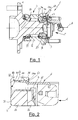
- FIGURE 1 is a section view of a preferred form of embodiment of a bearing wheel-hub unit with a speed sensor according to the present invention; and
- FIGURE 2 illustrates, on an enlarged scale, a detail of the unit which is shown in FIGURE 1.
- With reference to FIGURE 1, the number 1 is used to indicate, in its entirety, a bearing wheel-hub unit with a speed sensor 2.
- The unit 1 presents a rotation axis A, and comprises a rolling contact bearing 3, a connection flange 4 for a wheel (which is not illustrated) an encoder 5 which can rotate around the axis A, and a support collar 6 for the sensor 2.
- The
bearing 3 comprises aninner race 31 which can rotate around the axis A and which is integral with the flange 4, and anouter race 32, which is mounted around theinner race 31 by means of the interposition of two crowns of spheres 33, and which is provided with anannular border 34 which is arranged axially opposite the flange 4. - The
border 34 is axially limited by an annular surface 34a which is transverse to the axis A, and is radially delimited towards the axis A by acylindrical surface 34c which is co-axial to the axis A. - In addition, the
race 31 presents anannular insert 35, which is axially blocked by a rolledbead 36 in a position which is substantially co-axial to theborder 34 in order to maintain the unit 1 in its assembled configuration, and support the encoder 5 in a position which faces the sensor 2 and is inside the collar 6. - In addition, the collar 6 is connected to the
annular border 34 in order to define a centring element for the subsequent mounting of a mount (which is noted but not illustrated) onto the collar 6 itself, and which comprises acentring portion 61 for the centring of the above-mentioned mount, and an anchoring portion 62, which is axially near thecentring portion 61, and which is shrink-fit into thesurface 34c of theannular border 34 in order to anchor the collar 6 to theannular border 34 itself. - In addition, the collar 6 comprises a transition portion 63, which connects the anchoring portion 62 and the
centring portion 61 to each other, and which can be axially aligned with the annular surface 34a. - In particular, the anchoring portion 62 and the
centring portion 61 are of a cylindrical shape, and as the portion 62 presents an external diameter of dimensions which are greater than an external diameter of theportion 61, the portion 63 presents a substantially conical shape which tapers decreasingly towards theportion 61. - In addition, the portion 62 is provided with an end bevel 65 which is suitable for permitting an easier axial introduction of the collar 6 inside the
border 34 and which also facilitates the relative fixing operation. - In practice, once the collar 6 has been fixed inside the
border 34, the surface 34a remains free outside the collar 6 itself, and the unit 1 can be assembled on the above-mentioned mount, which is mounted onto the collar 6 in order to be centred in relation to the axis A, and which is placed in such a way as to axially abut against the surface 34a blocking at the same time the collar 6 itself due to the presence of the portion 63. - The mounting of the collar 6 inside the
border 34 leads to a reduction in the time necessary for the mechanical working of the unit 1 due to the fact that theborder 34 need only be worked on thesurface 34c, and also permits a reduction in the deformation of thebearing 3, following the fixture of theborder 34, with consequent advantages for the working life of thebearing 3 itself, and also for the stability of the sensor 2. - It is intended that the present invention should not be limited to the form of embodiment which is herein described and illustrated, which is to be considered as an example of a form of embodiment of the bearing wheel-hub group with speed sensor, and which may instead undergo further modifications to the shape and disposition of its parts, as well as to details pertaining to construction and assembly.
Claims (5)
- Bearing (3) wheel-hub unit (1) with a speed sensor (2), the unit (1) comprising a fixed outer race (32) which is provided with an annular border (34) which is arranged axially inside the unit (1), and a support collar (6), which supports the speed sensor (2), and which is connected to the said annular border (34) in order to define, in addition, a centring element for the subsequent mounting of a mount onto the collar (6) itself; the unit (1) being characterised by the fact that the collar (6) presents a centring portion (61) for the centring of the said mount, and an anchoring portion (62), which is axially near to the centring portion (61) and which is shrink-fit inside the annular border (34) in order to anchor the collar (6) to the annular border (34) itself.
- Unit according to Claim 1, characterised by the fact that the anchoring portion (62) presents an external diameter of dimensions which are greater than the dimensions of an external diameter of the centring portion (61).
- Unit according to Claim 2, characterised by the fact that the said annular border (34) presents a frontal surface (34a) which is transverse to a rotation axis (A) of the bearing (3), which defines an axial striker for the said mount.
- Unit according to Claim 3, characterised by the fact that the said frontal surface (34a) is a free surface.
- Unit according to Claim 4, characterised by the fact that the support collar (6) comprises a transition portion (63), which connects the anchoring portion (62) and the centring portion (61) to each other and which may be axially aligned with the said frontal surface and (34a).
Priority Applications (1)
| Application Number | Priority Date | Filing Date | Title |
|---|---|---|---|
| EP20050009027 EP1717465A1 (en) | 2005-04-25 | 2005-04-25 | Wheel-hub unit with a speed sensor |
Applications Claiming Priority (1)
| Application Number | Priority Date | Filing Date | Title |
|---|---|---|---|
| EP20050009027 EP1717465A1 (en) | 2005-04-25 | 2005-04-25 | Wheel-hub unit with a speed sensor |
Publications (1)
| Publication Number | Publication Date |
|---|---|
| EP1717465A1 true EP1717465A1 (en) | 2006-11-02 |
Family
ID=34935695
Family Applications (1)
| Application Number | Title | Priority Date | Filing Date |
|---|---|---|---|
| EP20050009027 Withdrawn EP1717465A1 (en) | 2005-04-25 | 2005-04-25 | Wheel-hub unit with a speed sensor |
Country Status (1)
| Country | Link |
|---|---|
| EP (1) | EP1717465A1 (en) |
Citations (5)
| Publication number | Priority date | Publication date | Assignee | Title |
|---|---|---|---|---|
| US5148104A (en) * | 1990-04-09 | 1992-09-15 | Nippon Seiko Kabushiki Kaisha | Hub unit with pulse rotor and cover mounted sensor for sensing rotational speed |
| US5550467A (en) * | 1992-04-29 | 1996-08-27 | Itt Automotive Europe Gmbh | Sensor including a follower for engaging the rotating portion of a bearing and having a sliding layer applied to the housing and encoder ring |
| DE19506838A1 (en) * | 1995-02-28 | 1996-08-29 | Fag Automobiltechnik Ag | Wheel bearing unit with rpm sensor for motor vehicle with ABS-ASR system |
| US5564838A (en) * | 1994-04-15 | 1996-10-15 | Skf France | Member for axial retention of a rolling-contact bearing with information sensor and rolling-contact bearing assembly including such a member |
| US6037766A (en) * | 1995-01-18 | 2000-03-14 | Itt Manufacturing Enterprises Inc. | Wheel bearing rotary motion sensor having sensor-accommodating housing |
-
2005
- 2005-04-25 EP EP20050009027 patent/EP1717465A1/en not_active Withdrawn
Patent Citations (5)
| Publication number | Priority date | Publication date | Assignee | Title |
|---|---|---|---|---|
| US5148104A (en) * | 1990-04-09 | 1992-09-15 | Nippon Seiko Kabushiki Kaisha | Hub unit with pulse rotor and cover mounted sensor for sensing rotational speed |
| US5550467A (en) * | 1992-04-29 | 1996-08-27 | Itt Automotive Europe Gmbh | Sensor including a follower for engaging the rotating portion of a bearing and having a sliding layer applied to the housing and encoder ring |
| US5564838A (en) * | 1994-04-15 | 1996-10-15 | Skf France | Member for axial retention of a rolling-contact bearing with information sensor and rolling-contact bearing assembly including such a member |
| US6037766A (en) * | 1995-01-18 | 2000-03-14 | Itt Manufacturing Enterprises Inc. | Wheel bearing rotary motion sensor having sensor-accommodating housing |
| DE19506838A1 (en) * | 1995-02-28 | 1996-08-29 | Fag Automobiltechnik Ag | Wheel bearing unit with rpm sensor for motor vehicle with ABS-ASR system |
Similar Documents
| Publication | Publication Date | Title |
|---|---|---|
| EP0592214B1 (en) | Compound ball-bearing | |
| US20080167149A1 (en) | Belt drive mechanism | |
| EP2466161B1 (en) | Bearing/hub unit for a motor-vehicle wheel | |
| EP1079125A3 (en) | Bearing device and method for measuring axial force | |
| EP2957432B1 (en) | Hub-bearing having a light alloy rotor-hub | |
| EP1717063B1 (en) | Bearing wheel hub unit | |
| EP2432650B1 (en) | Wheel bearing unit and method for producing the same | |
| US5596798A (en) | Apparatus for assembling a bearing unit, in particular a wheel bearing unit for motor vehicles | |
| CN110605937A (en) | Wheel hub with centering components | |
| CN1954156A (en) | Bearing with sensor | |
| EP2105322B1 (en) | Wheel bearing assembly, manufacturing method therefor, and calk jig | |
| JP4211539B2 (en) | Rolling bearing device | |
| EP1696239A1 (en) | Protection device for a speed sensor | |
| JP2009002480A5 (en) | ||
| JP7007924B2 (en) | Bearing equipment for wheels | |
| JP2007315411A (en) | Bearing device for wheel | |
| US20130301968A1 (en) | Hub spindle bearing unit for wheel | |
| EP1329728A2 (en) | Protection device for an encoder in a rolling bearing | |
| JP4547139B2 (en) | Tone wheel mounting structure | |
| JP4492436B2 (en) | Magnetic encoder and rolling bearing device using the same | |
| JP2008221337A (en) | Caulking method for vehicle hub unit | |
| JP2005076729A (en) | Rolling bearing device | |
| JP5017951B2 (en) | Hub unit bearing | |
| JP2005201456A5 (en) | ||
| JP2009144879A (en) | Bearing device for wheel |
Legal Events
| Date | Code | Title | Description |
|---|---|---|---|
| PUAI | Public reference made under article 153(3) epc to a published international application that has entered the european phase |
Free format text: ORIGINAL CODE: 0009012 |
|
| AK | Designated contracting states |
Kind code of ref document: A1 Designated state(s): AT BE BG CH CY CZ DE DK EE ES FI FR GB GR HU IE IS IT LI LT LU MC NL PL PT RO SE SI SK TR |
|
| AX | Request for extension of the european patent |
Extension state: AL BA HR LV MK YU |
|
| AKX | Designation fees paid | ||
| REG | Reference to a national code |
Ref country code: DE Ref legal event code: 8566 |
|
| STAA | Information on the status of an ep patent application or granted ep patent |
Free format text: STATUS: THE APPLICATION IS DEEMED TO BE WITHDRAWN |
|
| 18D | Application deemed to be withdrawn |
Effective date: 20070503 |