EP1717427A1 - Engine intake system with multiple and independent intake passages - Google Patents
Engine intake system with multiple and independent intake passages Download PDFInfo
- Publication number
- EP1717427A1 EP1717427A1 EP06008437A EP06008437A EP1717427A1 EP 1717427 A1 EP1717427 A1 EP 1717427A1 EP 06008437 A EP06008437 A EP 06008437A EP 06008437 A EP06008437 A EP 06008437A EP 1717427 A1 EP1717427 A1 EP 1717427A1
- Authority
- EP
- European Patent Office
- Prior art keywords
- bypass
- bypasses
- paths
- intake
- control valve
- Prior art date
- Legal status (The legal status is an assumption and is not a legal conclusion. Google has not performed a legal analysis and makes no representation as to the accuracy of the status listed.)
- Granted
Links
Images






Classifications
-
- F—MECHANICAL ENGINEERING; LIGHTING; HEATING; WEAPONS; BLASTING
- F02—COMBUSTION ENGINES; HOT-GAS OR COMBUSTION-PRODUCT ENGINE PLANTS
- F02D—CONTROLLING COMBUSTION ENGINES
- F02D9/00—Controlling engines by throttling air or fuel-and-air induction conduits or exhaust conduits
- F02D9/08—Throttle valves specially adapted therefor; Arrangements of such valves in conduits
- F02D9/10—Throttle valves specially adapted therefor; Arrangements of such valves in conduits having pivotally-mounted flaps
- F02D9/1035—Details of the valve housing
- F02D9/1055—Details of the valve housing having a fluid by-pass
-
- F—MECHANICAL ENGINEERING; LIGHTING; HEATING; WEAPONS; BLASTING
- F02—COMBUSTION ENGINES; HOT-GAS OR COMBUSTION-PRODUCT ENGINE PLANTS
- F02D—CONTROLLING COMBUSTION ENGINES
- F02D11/00—Arrangements for, or adaptations to, non-automatic engine control initiation means, e.g. operator initiated
- F02D11/06—Arrangements for, or adaptations to, non-automatic engine control initiation means, e.g. operator initiated characterised by non-mechanical control linkages, e.g. fluid control linkages or by control linkages with power drive or assistance
- F02D11/10—Arrangements for, or adaptations to, non-automatic engine control initiation means, e.g. operator initiated characterised by non-mechanical control linkages, e.g. fluid control linkages or by control linkages with power drive or assistance of the electric type
-
- F—MECHANICAL ENGINEERING; LIGHTING; HEATING; WEAPONS; BLASTING
- F02—COMBUSTION ENGINES; HOT-GAS OR COMBUSTION-PRODUCT ENGINE PLANTS
- F02D—CONTROLLING COMBUSTION ENGINES
- F02D9/00—Controlling engines by throttling air or fuel-and-air induction conduits or exhaust conduits
- F02D9/08—Throttle valves specially adapted therefor; Arrangements of such valves in conduits
- F02D9/10—Throttle valves specially adapted therefor; Arrangements of such valves in conduits having pivotally-mounted flaps
- F02D9/109—Throttle valves specially adapted therefor; Arrangements of such valves in conduits having pivotally-mounted flaps having two or more flaps
- F02D9/1095—Rotating on a common axis, e.g. having a common shaft
Definitions
- the present invention is based upon Japanese priority application No. 2005-130786 , which is hereby incorporated in its entirety herein by reference.
- the present invention relates to an improvement in a multicylinder engine intake system comprising: a plurality of intake paths communicating with intake ports of a multicylinder engine; a plurality of throttle valves for opening and closing the intake paths; a plurality of bypasses having upstream ends opened to atmosphere or the intake paths on upstream sides of the throttle valves, and having downstream ends opened to the intake paths on downstream sides of the throttle valves; and a common bypass control valve which opens and closes the bypasses.
- a bypass control valve in a multicylinder engine intake system is operated to regulate the amount of first idling air supplied to the engine through bypasses in order to appropriately control a first idling rotational speed mainly during engine warm-up operation.
- a multicylinder engine intake system of this type is known from, e.g., Japanese Patent Application Laid-open No. 2003-129924 .
- the bypass control valve is horizontally placed, leading to a possibility that fuel or water droplets entering the bypasses stays around the bypass control valve, and thus there is a need to provide an expensive sealing means for the bypass control valve. There is also a possibility that the fuel or water droplets staying around the bypass control valve hinders appropriate control of the amount of first idling air by the bypass control valve.
- the present invention has been achieved in view of the above-mentioned circumstances, and has an object to provide a multicylinder engine intake system which is capable of preventing fuel or water droplets from staying in by passes, in which no expensive sealing means for the bypass valve is required or a simple and inexpensive sealing means suffices, and which enables appropriate control of the amount of first idling air by the bypass control valve.
- a multicylinder engine intake system having comprising: a plurality of intake paths communicating with intake ports of a multicylinder engine; a plurality of throttle valves for opening and closing the intake paths; a plurality of bypasses having upstream ends opened to atmosphere or the intake paths on upstream sides of the throttle valves, and having downstream ends opened to the intake paths on downstream sides of the throttle valves; and a common bypass control valve which opens and closes the bypasses, wherein the bypass control valve is constituted by a valve body for opening the plurality of bypasses, and an electrically operated actuator provided above the valve body and operated for opening and closing the valve body; a portion of a bypass upstream path in the bypasses on upstream side of the valve body is placed below the valve body; and idling air paths branch off from the portion of the bypass upstream path to reach the corresponding intake paths.
- the bypass control valve is constituted by the valve body for opening the plurality of bypasses, and the electrically operated actuator provided above the valve body and operated for opening and closing the valve body.
- the bypass upstream side path on the upstream side of the valve has a portion placed below the valve body and the idling air paths branch off from the portion of the bypass upstream side path to reach the corresponding intake paths. Therefore, fuel or water droplets generated in the bypasses or entering the bypasses flows down to the bypass upstream path, and the fuel or water droplets can be discharged to the intake paths by being carried on air flows which are flowing from the idling air paths to the downstream sides of the intake paths and which are always formed in the bypass upstream path irrespective of the opening/closing state of the valve body. Thus, staying of the fuel or water droplets in the bypasses is prevented to ensure that the amount of first idling air can be appropriately regulated by the bypass valve.
- bypass upstream path is formed as a single path common to the plurality of bypasses.
- the bypass upstream path is formed as a single path common to the plurality of bypasses. This arrangement contributes to simplification of the structure of the bypass control valve as well as to simplification of the bypasses.
- a plurality of bypass downstream paths, on downstream side of the bypass control valve, of the plurality of bypasses are formed into a labyrinth shape.
- the plurality of bypass downstream paths of the bypasses on the downstream side of the bypass control valve are formed into a labyrinth shape, thereby attenuating gas blowback from the intake paths and preventing fuel and other unnecessary substances from entering the bypass control valve.
- reference character D denotes an intake system for a four-cylinder engine.
- the intake system D has first and second throttle bodies 1A and 1B disposed in parallel with each other, and is constructed to be a downdraft type wherein pairs of intake paths 2 1 , 2 2 ; 2 3 , 2 4 parallel to each other are provided in the throttle bodies 1A and 1B, respectively, with their downstream ends downwardly leading to an engine (not shown).
- An air cleaner 3 in which upstream ends of the intake paths 2 1 , 2 2 ; 2 3 , 2 4 are opened is attached to upper end portions of the two throttle bodies 1A and 1B.
- the two throttle bodies 1A and 1B are connected integrally with each other by connecting bolts 11.
- the pairs of intake paths 2 1 , 2 2 ; 2 3 , 2 4 are each disposed symmetrically with each other.
- valve shafts 4 which extend across the intake paths 2 1 , 2 2 ; 2 3 , 2 4 respectively are rotatably supported by the two throttle bodies 1A and 1B, and throttle valves 5 1 , 5 2 ; 5 3 , 5 4 for respectively opening/closing the intake paths 2 1 , 2 2 ; 2 3 , 2 4 are attached to the valve shafts 4.
- the two valve shafts 4 are disposed coaxially with each other, and have their opposed ends connected to each other by a throttle drum 6.
- the throttle valves 5 1 , 5 2 ; 5 3 , 5 4 are simultaneously opened or closed by rotating the throttle drum 6.
- Fuel injection valves 7 1 , 7 2 ; 7 3 , 7 4 for injecting fuel into intake ports of the engine through the intake paths 2 1 , 2 2 ; 2 3 , 2 4 downstream of the throttle valves 5 1 , 5 2 ; 5 3 , 5 4 are attached to the throttle bodies 1A and 1B.
- an air inlet chamber 8 is formed in the first throttle body 1A between the pair of intake paths 2 1 and 2 2 so as to be opened in an upper end surface of the first throttle body 1A on the air cleaner 3 side, and a guide path 9 extending from the air inlet chamber 8 is also formed in the first throttle body 1A.
- a bypass control valve 10 is connected to the guide path 9.
- the air inlet chamber 8 and the guide path 9 constitute a bypass upstream path 12a.
- Two pairs of bypass downstream paths 12b 1 , 12b 2 ; 12b 3 , 12b 4 extend from the bypass control valve 10.
- One pair of bypass downstream paths 12b 1 and 12b 1 are opened in the intake paths 2 1 and 2 2 , respectively, in the first throttle body 1A downstream of the respective throttle valves 5 1 and 5 2 .
- the other pair of bypass downstream paths 12b 3 and 12b 4 are opened in the intake paths 2 3 and 2 4 , respectively, in the second throttle body 1B downstream of the respective throttle valves 5 3 and 5 4 .
- bypass upstream path 12a and the bypass downstream paths 12b 1 , 12b 2 ; 12b 3 , 12b 4 constitute bypasses 12 1 , 12 2 ; 12 3 , 12 4 connected to the intake paths 2 1 , 2 2 ; 2 3 , 2 4 , respectively, while detouring around the respective throttle valves 5 1 , 5 2 ; 5 3 , 5 4 .
- the bypass upstream path 12a is a single path common to all the bypasses 12 1 , 12 2 ; 12 3 , 12 4 .
- the bypass control valve 10 has functions of distributing secondary air introduced into the single bypass upstream path 12a to the intake paths 2 1 , 2 2 ; 2 3 , 2 4 through the bypass downstream paths 12b 1 , 12b 2 ; 12b 3 , 12b 4 , respectively, and simultaneously controlling the amount of air distribution.
- bypasses 12 1 and 12 2 on the first throttle body 1A side and the bypass control valve 10 will be specifically described with reference to FIGS. 3, 5 and 6 to 9.
- a control block 15 is detachably joined to one side surface of the first throttle body 1A by a plurality of bolts 16, with a gasket 17 interposed therebetween.
- a cylindrical valve chamber 18 extending in a vertical direction is provided in the control block 15, and the above-described guide path 9 through which a lower portion of the air inlet chamber 8 communicates with a lower portion of the valve chamber 18 is provided between the first throttle body 1A and the control block 15.
- the bypass upstream path 12a is placed below a valve body 26.
- Two pairs of distribution chambers 32 1 , 32 2 ; 32 3 , 32 4 are provided around a lower portion of the valve chamber 18.
- Two pairs of measuring holes 19 1 , 19 2 ; 19 3 , 19 4 that provide communication between the valve chamber 18 and the distribution chambers 32 1 , 32 2 ; 32 3 , 32 4 are bored in a peripheral wall of the valve chamber 18.
- the valve body 26 in the form of a piston for regulating the opening degree of the measuring holes 19 1 , 19 2 ; 19 3 , 19 4 between the fully closed state and the fully opened state is slidably fitted from above into the valve chamber 18.
- a key groove 27 and a key 28 engageable with the key groove 27 are provided.
- the key groove 27 is provided on a side surface of the valve body 26.
- the key 28 is attached to the control block 15.
- An electrically operated actuator 25 which causes the valve body 26 to open and close the valve opening is fitted in a fitting hole 29 formed in the control block 15 continuously with the upper end of the valve chamber 18, and is fixed to the control block 15 by bolts.
- the electrically operated actuator 25 has a downwardly projecting output shaft 30 screwed into a threaded hole 31 formed in a central portion of the valve body 26.
- the valve body 26 can be moved upward or downward (for opening or closing) by rotating the output shaft 30 in the normal or reverse direction.
- a plate-shaped sealing member 23 which is brought into intimate contact with an outer peripheral surface of the output shaft 30 is interposed between a lower surface of the electrically operated actuator 25 and a bottom surface of the fitting hole 29.
- the valve body 26 and the electrically operated actuator 25 thus constitute the bypass control valve 10.
- the above-described pair of distribution chambers 32 1 and 32 2 and a pair of second labyrinth elements 35 disposed below the distribution chambers 32 1 and 32 2 are formed so as to be open in a joint surface 15a (see FIG. 7) of the control block 15 joined with respect to the first throttle body 1A.
- Partition walls 33 are provided between the distribution chambers 32 1 and 32 2 and the second labyrinth elements 35.
- a pair of first labyrinth elements 34 and a pair of communication holes 36 disposed below the first labyrinth elements 34 are formed so as to be open in a joint surface 1Aa (see FIG. 8).
- the first labyrinth elements 34 provide communication between the distribution chambers 32 1 and 32 2 and the second labyrinth elements 35, and the communication holes 36 communicate with the second labyrinth elements 35.
- Each of the communication holes 36 is formed by providing a plurality of drilled holes in alignment with each other. Terminal ends of the communication holes 36 are open in the intake paths 2 1 and 2 2 downstream of the throttle valves 5 1 and 5 2 .
- the measuring holes 19 1 and 19 2 , the distribution chambers 32 1 and 32 2 , the first labyrinth elements 34, the second labyrinth elements 35 and the communication holes 36 constitute the bypass downstream paths 12b 1 and 12b 2 , having a labyrinth shape, in the pair of bypasses 12 1 and 12 2 on the first throttle body 1A side.
- Idling air paths 37 1 and 37 2 provide communication between a lower portion of the air inlet chamber 8 and each of intermediate portions of the communication holes 36.
- Apair of idling regulation screws 38 1 and 38 2 capable of regulating the path area in intermediate portions of the idling air paths 37 1 and 37 2 are threaded into the first throttle body 1A (see FIG. 11 as well).
- a pair of joint pipes 40 1 and 40 2 which communicate with the other pair of distribution chambers 32 3 and 32 4 are attached to the control block 15.
- bypasses 12 3 and 12 4 on the second throttle body 1B side will be specifically described with reference to FIGS. 1, 4 and 10.
- one air inlet chamber 42 which is open on the air cleaner 3 side between the first and second intake paths 2 3 and 2 4 , a pair of distribution chambers 43 (only one of which is shown in FIG. 10) which are open in one side surface of the second throttle body 1B below the air inlet chamber 42, a pair of communication holes 44 which extend from the distribution chambers 43 to the first and second intake paths 2 3 and 2 4 downstream of the throttle valves 5 3 and 5 4 , and a pair of idling air paths 37 3 and 37 4 which provide communication between intermediate portions of the communication holes 44 and a lower portion of the air inlet chamber 42.
- a joint block 41 having a pair of joint pipes 48 1 and 48 2 communicating with the distribution chambers 43 is joined to the one side surface of the second throttle body 1B by bolts 47 with a gasket 50 interposed therebetween.
- the joint pipes 40 1 and 40 2 of the control block 15 and the joint pipes 48 1 and 48 2 of the joint block 41 are connected to each other by a pair of communication pipes 49 1 and 49 2 .
- the measuring holes 19 3 and 19 4 , the distribution chambers 32 3 and 32 4 , the communication pipes 49 1 and 49 2 and the communication holes 44 constitute the bypass downstream paths 12b 3 and 12b 4 in the pair of bypasses 12 3 and 12 4 on the second throttle body 1B side.
- a pair of idling regulation screws 38 3 and 38 4 capable of regulating the path area in intermediate portions of the idling air paths 37 3 and 37 4 are threaded into the second throttle body 1B.
- the idling air paths 37 1 , 37 2 ; 37 3 , 37 4 are respectively provided for the purpose of maintaining the amount of idling air necessary for ordinary idling of the engine when the bypasses 12 1 , 12 2 ; 12 3 , 12 4 are completely closed by the bypass control valve 10.
- the amount of idling air is regulated by means of the idling regulation screws 38 1 and 38 2 ; 38 3 and 38 4 .
- the downstream ends of the bypasses 12 1 , 12 2 ; 12 3 , 12 4 opened in downstream portions of the intake paths 2 1 , 2 2 ; 2 3 , 2 4 of the first and second throttle bodies 1A and 1B, i.e., the outlet opening degrees of the communication holes 36 and 44, are formed as throttle holes 36a and 44a, respectively.
- the throttle holes 44a on the second throttle body 1B side where the bypass control valve 10 is not provided are formed so as to be larger in diameter than the throttle holes 36a on the first throttle body 1A side where the bypass control valve 10 is provided.
- the difference between the diameters of the throttle holes 36a and 44a is determined by the difference between the lengths of the corresponding bypass downstream paths 12b 1 , 12b 2 ; 12b 3 , 12b 4 . That is, on the first throttle body 1A side, the bypass control valve 10 supported on the first throttle body 1A is placed at equal and comparatively small distances from the pair of intake paths 2 1 and 2 2 , so that the lengths of the bypass downstream paths 12b 1 and 12b 2 on the first throttle body 1A side are set to comparatively small and equal to each other. Accordingly, the throttle holes 36a of the bypass downstream paths 12b 1 and 12b 2 are formed so as to be comparatively small and equal in diameter.
- a controller (not shown) operates the electrically operated actuator 25 for the bypass control valve 10 by supplying the actuator 25 with a current corresponding to the engine temperature.
- the valve body 26 is lifted by a large amount to regulate the opening degrees of the measuring holes 19 1 , 19 2 ; 19 3 , 19 4 to be large. Therefore, in the state where the throttle valves 5 1 , 5 2 ; 5 3 , 5 4 are fully opened, the amount of first idling air supplied to the engine through the bypasses 12 1 , 12 2 ; 12 3 , 12 4 is controlled to be comparatively large by means of the measuring holes 19 1 , 19 2 ; 19 3 , 19 4 .
- the amount of fuel according to the amount of operation of the electrically operated actuator 25 are injected from the fuel injection valves 7 1 , 7 2 ; 7 3 , toward the downstream sides of the intake paths 2 1 , 2 2 ; 2 3 , 2 4 .
- the engine receives the thus-supplied air and fuel to maintain an appropriate first idling speed so that the warm-up operation progresses.
- bypass control valve 10 Since the bypass control valve 10 is attached to the first throttle body 1A side, the need for an attachment member exclusively for attachment of the bypass control valve 10 can be eliminated to simplify the structure of the intake system D. Also, the downstream ends of the bypasses 12 1 , 12 2 ; 12 3 , 12 4 opened in downstream portions of the intake paths 2 1 , 2 2 ; 2 3 , 2 4 of the first and second throttle bodies 1A and 1B are formed as throttle holes 36a and 44a, respectively, the throttle holes 36a on the first throttle body 1A side where the bypass control valve 10 has a smaller diameter, and the throttle holes 44a on the second throttle body 1B side where the bypass control valve 10 has a larger diameter.
- the flow path resistances of all the plurality of bypass downstream paths 12b 1 , 12b 2 ; 12b 3 , 12b 4 can be made uniform, although the lengths of the bypass downstream paths 12b 1 , 12b 2 ; 12b 3 , 12b 4 from the bypass control valve 10 to each of the throttle bodies 1A and 1B are smaller on the first throttle body 1A side and longer on the second throttle body 1B side. Consequently, the amount of first idling air supplied to the plurality of cylinders of the engine through the plurality of bypass downstream paths 12b 1 , 12b 2 ; 12b 3 , 12b 4 can be equalized.
- the electrically operated actuator 25 moves the valve body 26 downward to reduce the opening degrees of the measuring holes 19 1 , 19 2 ; 19 3 , 19 4 corresponding to the increase in engine temperature.
- the amount of first idling air supplied to the engine through the bypasses 12 1 , 12 2 ; 12 3 , 12 4 is thereby reduced to lower the engine rotational speed.
- the electrically operated actuator 25 moves the valve body 26 into the completely closed state to completely close the bypasses 12 1 , 12 2 ; 12 3 , 12 4 .
- the throttle valves 5 1 , 5 2 ; 5 3 , 5 4 in the intake paths 2 1 , 2 2 ; 2 3 , 2 4 are closed, only the least amount of air are supplied to the engine through the idling air supply paths 37 1 , 37 2 ; 37 3 , 37 4 , thus controlling the engine at the ordinary idling rotational speed.
- the amount of idling air flowing through the idling air supply paths 37 1 , 37 2 ; 37 3 , 37 4 can be individually regulated by turning the idling regulation screws 38 1 , 38 2 ; 38 3 , 38 4 .
- the bypass control valve 10 provided in the first throttle body 1A is constituted by the valve body 26 for opening/closing the pairs of bypasses 12 1 , 12 2 ; 12 3 , 12 4 , and the electrically operated actuator 25 provided above the valve body 26 and operated for opening/closing the valve body 26.
- This simple arrangement ensures that even in a case where water droplets are generated in the bypasses 12 1 and 12 2 on the first throttle body 1A side near the bypass control valve 10 in particular or even in a case where fuel enters the 12 1 and 12 2 due to an engine blowback phenomenon, the fuel or water droplets can be prevented from flowing into the electrically operated actuator 25. Therefore no expensive sealing means is required for the electrically operated actuator 25, and only an inexpensive sealing suffices.
- the bypass upstream side path 12a on the upstream side of the valve 26, i.e., the air inlet chamber 8 and the guide path 9 are placed below the valve body 26, and the idling air paths 37 1 and 37 2 extend from a lower portion of the air inlet chamber 8 to the intake paths 2 1 and 2 2 in the first throttle body 1A.
- the air inlet chamber 8 and the guide path 9 constituting the bypass upstream path 12a form a single path common to the bypasses 12 3 and 12 4 on the second throttle body 1B side as well as to the bypasses 12 1 and 12 2 on the first throttle body 1A side.
- This arrangement contributes to simplification of the structure of the bypass control valve 10 as well as to simplification of the bypasses 12 1 , 12 2 ; 12 3 , 12 4 .
- the communication pipes 49 1 and 49 2 are provided only by piping between the bypass control valve 10 and the second throttle body 1B not having the valve 10, thus simplifying the pipe arrangement.
- bypass downstream paths 12b 1 and 12b 2 provided downstream of the bypass control valve 10 near the bypass control valve 10 on the first throttle body 1A side are constituted by the first labyrinth elements 34 and the second labyrinth elements 35 in a labyrinth shape, thereby attenuating gas blowback from the intake paths 2 1 and 2 2 and preventing fuel and other unnecessary substances from entering the bypass control valve 10.
- the first throttle body 1A and the control block 15 in which the bypass control valve 10 is mounted are constructed as separate bodies joinable to and separable from each other, and correspondingly the plurality of bypasses 12 1 and 12 2 are also formed separately from each other, thus facilitating the formation of the bypasses 12 1 , 12 2 ; 12 3 , 12 4 . Further, since the control block 15 and the bypass control valve 10 can be assembled into one unit separately from the first throttle body 1A, the assemblability of the components becomes excellent. Furthermore, since the control block 15 can be separate from the first throttle body 1A, the ease of maintenance of the bypass control valve 10 and other components becomes excellent.
- the present invention is not limited to the above-described embodiment thereof.
- Various changes in design of the present invention can be made without departing from the subject matter of the present invention.
- the first throttle body 1A having the bypass control valve 10 may be singly used as an intake system for a two-cylinder engine.
- the present invention is also applicable to a horizontal throttle body in which intake paths are generally horizontal.
- the vertical positional relationship among the electrically operated actuator 25, the valve body 26 and the bypass upstream path 12a is same as that in the above-described embodiment.
- a multicylinder engine intake system includes: a plurality of intake paths; a plurality of bypasses detouring throttle valves and connected to the intake paths; and a common bypass control valve for opening and closing the bypasses.
- the bypass control valve is constituted by a valve body and an electrically operated actuator provided above the valve body and operated for opening and closing the valve body.
- a portion of a bypass upstream path in the bypasses on upstream side of the valve body is placed below the valve body. Idling air paths branch off from the portion of the bypass upstream path to reach the corresponding intake paths.
Landscapes
- Engineering & Computer Science (AREA)
- Chemical & Material Sciences (AREA)
- Combustion & Propulsion (AREA)
- Mechanical Engineering (AREA)
- General Engineering & Computer Science (AREA)
- Control Of Throttle Valves Provided In The Intake System Or In The Exhaust System (AREA)
Abstract
Description
- The present invention is based upon
Japanese priority application No. 2005-130786 - The present invention relates to an improvement in a multicylinder engine intake system comprising: a plurality of intake paths communicating with intake ports of a multicylinder engine; a plurality of throttle valves for opening and closing the intake paths; a plurality of bypasses having upstream ends opened to atmosphere or the intake paths on upstream sides of the throttle valves, and having downstream ends opened to the intake paths on downstream sides of the throttle valves; and a common bypass control valve which opens and closes the bypasses.
- A bypass control valve in a multicylinder engine intake system is operated to regulate the amount of first idling air supplied to the engine through bypasses in order to appropriately control a first idling rotational speed mainly during engine warm-up operation.
- A multicylinder engine intake system of this type is known from, e.g.,
Japanese Patent Application Laid-open No. 2003-129924 - In the multicylinder engine intake system disclosed in
Japanese Patent Application Laid-open No. 2003-129924 - The present invention has been achieved in view of the above-mentioned circumstances, and has an object to provide a multicylinder engine intake system which is capable of preventing fuel or water droplets from staying in by passes, in which no expensive sealing means for the bypass valve is required or a simple and inexpensive sealing means suffices, and which enables appropriate control of the amount of first idling air by the bypass control valve.
- In order to achieve the above object, according to a first feature of the present invention, there is provided a multicylinder engine intake system having comprising: a plurality of intake paths communicating with intake ports of a multicylinder engine; a plurality of throttle valves for opening and closing the intake paths; a plurality of bypasses having upstream ends opened to atmosphere or the intake paths on upstream sides of the throttle valves, and having downstream ends opened to the intake paths on downstream sides of the throttle valves; and a common bypass control valve which opens and closes the bypasses, wherein the bypass control valve is constituted by a valve body for opening the plurality of bypasses, and an electrically operated actuator provided above the valve body and operated for opening and closing the valve body; a portion of a bypass upstream path in the bypasses on upstream side of the valve body is placed below the valve body; and idling air paths branch off from the portion of the bypass upstream path to reach the corresponding intake paths.
- With the first feature of the present invention, the bypass control valve is constituted by the valve body for opening the plurality of bypasses, and the electrically operated actuator provided above the valve body and operated for opening and closing the valve body. This simple arrangement ensures that fuel or water droplets generated in the bypasses or entering the bypasses is prevented from flowing into the electrically operated actuator. Therefore no expensive sealing means is required for the electrically operated actuator, and only an inexpensive sealing means suffices.
- The bypass upstream side path on the upstream side of the valve has a portion placed below the valve body and the idling air paths branch off from the portion of the bypass upstream side path to reach the corresponding intake paths. Therefore, fuel or water droplets generated in the bypasses or entering the bypasses flows down to the bypass upstream path, and the fuel or water droplets can be discharged to the intake paths by being carried on air flows which are flowing from the idling air paths to the downstream sides of the intake paths and which are always formed in the bypass upstream path irrespective of the opening/closing state of the valve body. Thus, staying of the fuel or water droplets in the bypasses is prevented to ensure that the amount of first idling air can be appropriately regulated by the bypass valve.
- According to a second feature of the present invention, in addition to the first feature, the bypass upstream path is formed as a single path common to the plurality of bypasses.
- With the second feature of the present invention, the bypass upstream path is formed as a single path common to the plurality of bypasses. This arrangement contributes to simplification of the structure of the bypass control valve as well as to simplification of the bypasses.
- According to a third feature of the present invention, in addition to the first or second feature, a plurality of bypass downstream paths, on downstream side of the bypass control valve, of the plurality of bypasses are formed into a labyrinth shape.
- With the third feature of the present invention, the plurality of bypass downstream paths of the bypasses on the downstream side of the bypass control valve are formed into a labyrinth shape, thereby attenuating gas blowback from the intake paths and preventing fuel and other unnecessary substances from entering the bypass control valve.
- The above-mentioned object, other objects, characteristics, and advantages of the present invention will become apparent from a preferred embodiment which will be described in detail below by reference to the attached drawings.
-
- FIG. 1 is a front view of a multicylinder engine intake system according to the present invention.
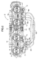
- FIG. 2 a plan view as seen in the direction of
arrow 2 in FIG. 1. - FIG. 3 is an enlarged view of portion 3 in FIG. 1.
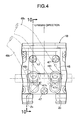
- FIG. 4 is an enlarged view of
portion 4 in FIG. 1. - FIG. 5 is a sectional view taken along line 5-5 in FIG. 3.
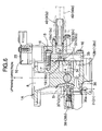
- FIG. 6 is a sectional view taken along line 6-6 in FIG. 3.
- FIG. 7 is a sectional view taken along line 7-7 in FIG. 5.
- FIG. 8 is a sectional view taken along line 8-8 in FIG. 5.
- FIG. 9 is a sectional view taken along line 9-9 in FIG. 8.
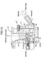
- FIG. 10 is a sectional view taken along line 10-10 in FIG. 4.
- FIG. 11 is a diagram showing the entire air path scheme of the intake system.
- Referring to FIGS. 1, 2 and 11, reference character D denotes an intake system for a four-cylinder engine. The intake system D has first and
second throttle bodies intake paths throttle bodies intake paths throttle bodies throttle bodies bolts 11. The pairs ofintake paths - As shown in FIGS. 1 to 6,
valve shafts 4 which extend across theintake paths throttle bodies intake paths valve shafts 4. The twovalve shafts 4 are disposed coaxially with each other, and have their opposed ends connected to each other by athrottle drum 6. The throttle valves 51, 52; 53, 54 are simultaneously opened or closed by rotating thethrottle drum 6. Fuel injection valves 71, 72; 73, 74 for injecting fuel into intake ports of the engine through theintake paths throttle bodies - As shown in FIGS. 3, 5, 6, and 11, an
air inlet chamber 8 is formed in thefirst throttle body 1A between the pair ofintake paths first throttle body 1A on the air cleaner 3 side, and aguide path 9 extending from theair inlet chamber 8 is also formed in thefirst throttle body 1A. Abypass control valve 10 is connected to theguide path 9. Theair inlet chamber 8 and theguide path 9 constitute a bypassupstream path 12a. - Two pairs of bypass downstream paths 12b1, 12b2; 12b3, 12b4 extend from the
bypass control valve 10. One pair of bypass downstream paths 12b1 and 12b1 are opened in theintake paths first throttle body 1A downstream of the respective throttle valves 51 and 52. The other pair of bypass downstream paths 12b3 and 12b4 are opened in theintake paths second throttle body 1B downstream of the respective throttle valves 53 and 54. - Thus, as clearly shown in FIG. 11, the bypass
upstream path 12a and the bypass downstream paths 12b1, 12b2; 12b3, 12b4 constitute bypasses 121, 122; 123, 124 connected to theintake paths upstream path 12a is a single path common to all the bypasses 121, 122; 123, 124. Thebypass control valve 10 has functions of distributing secondary air introduced into the single bypassupstream path 12a to theintake paths - The structures of the bypasses 121 and 122 on the
first throttle body 1A side and thebypass control valve 10 will be specifically described with reference to FIGS. 3, 5 and 6 to 9. - A
control block 15 is detachably joined to one side surface of thefirst throttle body 1A by a plurality ofbolts 16, with agasket 17 interposed therebetween. Acylindrical valve chamber 18 extending in a vertical direction is provided in thecontrol block 15, and the above-describedguide path 9 through which a lower portion of theair inlet chamber 8 communicates with a lower portion of thevalve chamber 18 is provided between thefirst throttle body 1A and thecontrol block 15. Thus, the bypassupstream path 12a is placed below avalve body 26. - Two pairs of distribution chambers 321, 322; 323, 324 are provided around a lower portion of the
valve chamber 18. Two pairs ofmeasuring holes valve chamber 18 and the distribution chambers 321, 322; 323, 324 are bored in a peripheral wall of thevalve chamber 18. - The
valve body 26 in the form of a piston for regulating the opening degree of themeasuring holes valve chamber 18. To prevent thevalve body 26 from rotating, a key groove 27 and a key 28 engageable with the key groove 27 are provided. The key groove 27 is provided on a side surface of thevalve body 26. The key 28 is attached to thecontrol block 15. An electrically operatedactuator 25 which causes thevalve body 26 to open and close the valve opening is fitted in afitting hole 29 formed in thecontrol block 15 continuously with the upper end of thevalve chamber 18, and is fixed to thecontrol block 15 by bolts. The electrically operatedactuator 25 has a downwardly projectingoutput shaft 30 screwed into a threaded hole 31 formed in a central portion of thevalve body 26. Thevalve body 26 can be moved upward or downward (for opening or closing) by rotating theoutput shaft 30 in the normal or reverse direction. A plate-shaped sealingmember 23 which is brought into intimate contact with an outer peripheral surface of theoutput shaft 30 is interposed between a lower surface of the electrically operatedactuator 25 and a bottom surface of thefitting hole 29. Thevalve body 26 and the electrically operatedactuator 25 thus constitute thebypass control valve 10. - In the
control block 15, the above-described pair of distribution chambers 321 and 322 and a pair ofsecond labyrinth elements 35 disposed below the distribution chambers 321 and 322 are formed so as to be open in ajoint surface 15a (see FIG. 7) of thecontrol block 15 joined with respect to thefirst throttle body 1A.Partition walls 33 are provided between the distribution chambers 321 and 322 and thesecond labyrinth elements 35. In thefirst throttle body 1A, a pair offirst labyrinth elements 34 and a pair of communication holes 36 disposed below thefirst labyrinth elements 34 are formed so as to be open in a joint surface 1Aa (see FIG. 8). When thecontrol block 15 is joined to thefirst throttle body 1A, thefirst labyrinth elements 34 provide communication between the distribution chambers 321 and 322 and thesecond labyrinth elements 35, and the communication holes 36 communicate with thesecond labyrinth elements 35. Each of the communication holes 36 is formed by providing a plurality of drilled holes in alignment with each other. Terminal ends of the communication holes 36 are open in theintake paths - Thus, the measuring holes 191 and 192, the distribution chambers 321 and 322, the
first labyrinth elements 34, thesecond labyrinth elements 35 and the communication holes 36 constitute the bypass downstream paths 12b1 and 12b2, having a labyrinth shape, in the pair of bypasses 121 and 122 on thefirst throttle body 1A side. - Idling air paths 371 and 372 provide communication between a lower portion of the
air inlet chamber 8 and each of intermediate portions of the communication holes 36. Apair of idling regulation screws 381 and 382 capable of regulating the path area in intermediate portions of the idling air paths 371 and 372 are threaded into thefirst throttle body 1A (see FIG. 11 as well). - A pair of joint pipes 401 and 402 which communicate with the other pair of distribution chambers 323 and 324 are attached to the
control block 15. - The structure of the bypasses 123 and 124 on the
second throttle body 1B side will be specifically described with reference to FIGS. 1, 4 and 10. - Provided in the
second throttle body 1B are oneair inlet chamber 42 which is open on the air cleaner 3 side between the first andsecond intake paths second throttle body 1B below theair inlet chamber 42, a pair of communication holes 44 which extend from thedistribution chambers 43 to the first andsecond intake paths air inlet chamber 42. Ajoint block 41 having a pair of joint pipes 481 and 482 communicating with thedistribution chambers 43 is joined to the one side surface of thesecond throttle body 1B bybolts 47 with agasket 50 interposed therebetween. The joint pipes 401 and 402 of thecontrol block 15 and the joint pipes 481 and 482 of thejoint block 41 are connected to each other by a pair of communication pipes 491 and 492. - Thus, the measuring holes 193 and 194, the distribution chambers 323 and 324, the communication pipes 491 and 492 and the communication holes 44 constitute the bypass downstream paths 12b3 and 12b4 in the pair of bypasses 123 and 124 on the
second throttle body 1B side. - A pair of idling regulation screws 383 and 384 capable of regulating the path area in intermediate portions of the idling air paths 373 and 374 are threaded into the
second throttle body 1B. - The idling air paths 371, 372; 373, 374 are respectively provided for the purpose of maintaining the amount of idling air necessary for ordinary idling of the engine when the bypasses 121, 122; 123, 124 are completely closed by the
bypass control valve 10. The amount of idling air is regulated by means of the idling regulation screws 381 and 382; 383 and 384. - As shown in FIGS. 6, 10 and 11, the downstream ends of the bypasses 121, 122; 123, 124 opened in downstream portions of the
intake paths second throttle bodies throttle holes second throttle body 1B side where thebypass control valve 10 is not provided are formed so as to be larger in diameter than the throttle holes 36a on thefirst throttle body 1A side where thebypass control valve 10 is provided. The difference between the diameters of the throttle holes 36a and 44a is determined by the difference between the lengths of the corresponding bypass downstream paths 12b1, 12b2; 12b3, 12b4. That is, on thefirst throttle body 1A side, thebypass control valve 10 supported on thefirst throttle body 1A is placed at equal and comparatively small distances from the pair ofintake paths first throttle body 1A side are set to comparatively small and equal to each other. Accordingly, the throttle holes 36a of the bypass downstream paths 12b1 and 12b2 are formed so as to be comparatively small and equal in diameter. On the other hand, on thesecond throttle body 1B side where thethrottle control valve 10 is not provided, the lengths of the bypass downstream paths 12b3 and 12b4 between thethrottle control valve 10 andintake paths - The operation of this embodiment will next be described.
- During engine warm-up operation, a controller (not shown) operates the electrically operated
actuator 25 for thebypass control valve 10 by supplying theactuator 25 with a current corresponding to the engine temperature. When the engine temperature is low, thevalve body 26 is lifted by a large amount to regulate the opening degrees of the measuring holes 191, 192; 193, 194 to be large. Therefore, in the state where the throttle valves 51, 52; 53, 54 are fully opened, the amount of first idling air supplied to the engine through the bypasses 121, 122; 123, 124 is controlled to be comparatively large by means of the measuring holes 191, 192; 193, 194. Simultaneously, the amount of fuel according to the amount of operation of the electrically operatedactuator 25 are injected from the fuel injection valves 71, 72; 73, toward the downstream sides of theintake paths - Since the
bypass control valve 10 is attached to thefirst throttle body 1A side, the need for an attachment member exclusively for attachment of thebypass control valve 10 can be eliminated to simplify the structure of the intake system D. Also, the downstream ends of the bypasses 121, 122; 123, 124 opened in downstream portions of theintake paths second throttle bodies throttle holes first throttle body 1A side where thebypass control valve 10 has a smaller diameter, and the throttle holes 44a on thesecond throttle body 1B side where thebypass control valve 10 has a larger diameter. Therefore, the flow path resistances of all the plurality of bypass downstream paths 12b1, 12b2; 12b3, 12b4 can be made uniform, although the lengths of the bypass downstream paths 12b1, 12b2; 12b3, 12b4 from thebypass control valve 10 to each of thethrottle bodies first throttle body 1A side and longer on thesecond throttle body 1B side. Consequently, the amount of first idling air supplied to the plurality of cylinders of the engine through the plurality of bypass downstream paths 12b1, 12b2; 12b3, 12b4 can be equalized. - Even in such a first idling state, certain flows of air supplied to the engine exist in the idling air paths 371, 372; 373, 374.
- As the engine temperature rises with the progress of the warm-up operation, the electrically operated
actuator 25 moves thevalve body 26 downward to reduce the opening degrees of the measuring holes 191, 192; 193, 194 corresponding to the increase in engine temperature. The amount of first idling air supplied to the engine through the bypasses 121, 122; 123, 124 is thereby reduced to lower the engine rotational speed. When the temperature of the engine becomes equal to a predetermined high temperature, the electrically operatedactuator 25 moves thevalve body 26 into the completely closed state to completely close the bypasses 121, 122; 123, 124. Therefore, in the state where the throttle valves 51, 52; 53, 54 in theintake paths - The
bypass control valve 10 provided in thefirst throttle body 1A is constituted by thevalve body 26 for opening/closing the pairs of bypasses 121, 122; 123, 124, and the electrically operatedactuator 25 provided above thevalve body 26 and operated for opening/closing thevalve body 26. This simple arrangement ensures that even in a case where water droplets are generated in the bypasses 121 and 122 on thefirst throttle body 1A side near thebypass control valve 10 in particular or even in a case where fuel enters the 121 and 122 due to an engine blowback phenomenon, the fuel or water droplets can be prevented from flowing into the electrically operatedactuator 25. Therefore no expensive sealing means is required for the electrically operatedactuator 25, and only an inexpensive sealing suffices. - The bypass
upstream side path 12a on the upstream side of thevalve 26, i.e., theair inlet chamber 8 and theguide path 9 are placed below thevalve body 26, and the idling air paths 371 and 372 extend from a lower portion of theair inlet chamber 8 to theintake paths first throttle body 1A. Therefore, fuel or water droplets generated in the bypasses 121 and 122 or entering the bypasses 121 and 122 flows down to the bypassupstream path 12a, and the fuel or water droplets are discharged to theintake paths intake paths upstream path 12a irrespective of the opening/closing state of thevalve body 26. Thus, staying of the fuel or water droplets in the bypasses 121 and 122 is prevented to ensure that the amount of first idling air is appropriately regulated by thebypass valve 10. - The
air inlet chamber 8 and theguide path 9 constituting the bypassupstream path 12a form a single path common to the bypasses 123 and 124 on thesecond throttle body 1B side as well as to the bypasses 121 and 122 on thefirst throttle body 1A side. This arrangement contributes to simplification of the structure of thebypass control valve 10 as well as to simplification of the bypasses 121, 122; 123, 124. Also, the communication pipes 491 and 492 are provided only by piping between thebypass control valve 10 and thesecond throttle body 1B not having thevalve 10, thus simplifying the pipe arrangement. - The bypass downstream paths 12b1 and 12b2 provided downstream of the
bypass control valve 10 near thebypass control valve 10 on thefirst throttle body 1A side are constituted by thefirst labyrinth elements 34 and thesecond labyrinth elements 35 in a labyrinth shape, thereby attenuating gas blowback from theintake paths bypass control valve 10. - The
first throttle body 1A and thecontrol block 15 in which thebypass control valve 10 is mounted are constructed as separate bodies joinable to and separable from each other, and correspondingly the plurality of bypasses 121 and 122 are also formed separately from each other, thus facilitating the formation of the bypasses 121, 122; 123, 124. Further, since thecontrol block 15 and thebypass control valve 10 can be assembled into one unit separately from thefirst throttle body 1A, the assemblability of the components becomes excellent. Furthermore, since thecontrol block 15 can be separate from thefirst throttle body 1A, the ease of maintenance of thebypass control valve 10 and other components becomes excellent. - The present invention is not limited to the above-described embodiment thereof. Various changes in design of the present invention can be made without departing from the subject matter of the present invention. For example, the
first throttle body 1A having thebypass control valve 10 may be singly used as an intake system for a two-cylinder engine. The present invention is also applicable to a horizontal throttle body in which intake paths are generally horizontal. Also in this case, the vertical positional relationship among the electrically operatedactuator 25, thevalve body 26 and the bypassupstream path 12a is same as that in the above-described embodiment. - A multicylinder engine intake system includes: a plurality of intake paths; a plurality of bypasses detouring throttle valves and connected to the intake paths; and a common bypass control valve for opening and closing the bypasses. The bypass control valve is constituted by a valve body and an electrically operated actuator provided above the valve body and operated for opening and closing the valve body. A portion of a bypass upstream path in the bypasses on upstream side of the valve body is placed below the valve body. Idling air paths branch off from the portion of the bypass upstream path to reach the corresponding intake paths. Thus, it is possible to prevent fuel or dater droplets from staying in the bypasses and appropriately control the amount of first idling air by the bypass control valve.
Claims (4)
- A multicylinder engine intake system comprising:a plurality of intake paths communicating with intake ports of a multicylinder engine;a plurality of throttle valves for opening and closing the intake paths;a plurality of bypasses having upstream ends opened to atmosphere or the intake paths on upstream sides of the throttle valves, and having downstream ends opened to the intake paths on downstream sides of the throttle valves; anda common bypass control valve which opens and closes the bypasses,wherein the bypass control valve is constituted by a valve body for opening the plurality of bypasses, and an electrically operated actuator provided above the valve body and operated for opening and closing the valve body; a portion of a bypass upstream path in the bypasses on upstream side of the valve body is placed below the valve body; and idling air paths branch off from the portion of the bypass upstream path to reach the corresponding intake paths.
- The multicylinder engine intake system according to claim 1, wherein the bypass upstream path is formed as a single path common to the plurality of bypasses.
- The multicylinder engine intake system according to claim 1, wherein a plurality of bypass downstream paths, on downstream side of the bypass control valve, of the plurality of bypasses are formed into a labyrinth shape.
- The multicylinder engine intake system according to claim 2, wherein a plurality of bypass downstream paths, on downstream side of the bypass control valve, of the plurality of bypasses are formed into a labyrinth shape.
Applications Claiming Priority (1)
| Application Number | Priority Date | Filing Date | Title |
|---|---|---|---|
| JP2005130786A JP4217227B2 (en) | 2005-04-28 | 2005-04-28 | Intake device for multi-cylinder engine |
Publications (2)
| Publication Number | Publication Date |
|---|---|
| EP1717427A1 true EP1717427A1 (en) | 2006-11-02 |
| EP1717427B1 EP1717427B1 (en) | 2008-03-05 |
Family
ID=36655043
Family Applications (1)
| Application Number | Title | Priority Date | Filing Date |
|---|---|---|---|
| EP06008437A Expired - Lifetime EP1717427B1 (en) | 2005-04-28 | 2006-04-24 | Engine intake system with multiple and independent intake passages |
Country Status (4)
| Country | Link |
|---|---|
| US (1) | US7231899B2 (en) |
| EP (1) | EP1717427B1 (en) |
| JP (1) | JP4217227B2 (en) |
| DE (1) | DE602006000613T2 (en) |
Cited By (1)
| Publication number | Priority date | Publication date | Assignee | Title |
|---|---|---|---|---|
| CN111226028A (en) * | 2018-01-26 | 2020-06-02 | 株式会社三国 | Throttle device |
Families Citing this family (5)
| Publication number | Priority date | Publication date | Assignee | Title |
|---|---|---|---|---|
| JP4042991B2 (en) * | 2005-04-28 | 2008-02-06 | 株式会社ケーヒン | Intake device for multi-cylinder engine |
| JP4767080B2 (en) * | 2005-08-31 | 2011-09-07 | 本田技研工業株式会社 | Intake structure of V-type internal combustion engine |
| JP5707967B2 (en) * | 2011-01-24 | 2015-04-30 | 日産自動車株式会社 | Supercharging pressure diagnosis device for internal combustion engine |
| JP5932522B2 (en) * | 2012-06-29 | 2016-06-08 | 本田技研工業株式会社 | Intake device for multi-cylinder engine |
| JP5946371B2 (en) * | 2012-08-29 | 2016-07-06 | 本田技研工業株式会社 | Throttle body structure |
Citations (3)
| Publication number | Priority date | Publication date | Assignee | Title |
|---|---|---|---|---|
| EP0905366A2 (en) * | 1997-09-24 | 1999-03-31 | Honda Giken Kogyo Kabushiki Kaisha | Starting control valve assembly for multiple throttle |
| US20020029759A1 (en) * | 2000-09-12 | 2002-03-14 | Takashi Akagi | Throttle unit of engine |
| US20050022780A1 (en) * | 2003-07-31 | 2005-02-03 | Denso Corporation | Air amount control valve having valve body for controlling air passage |
Family Cites Families (2)
| Publication number | Priority date | Publication date | Assignee | Title |
|---|---|---|---|---|
| US6202626B1 (en) * | 1997-01-31 | 2001-03-20 | Yamaha Hatsudoki Kabushiki Kaisha | Engine having combustion control system |
| JP2003129924A (en) | 2001-10-23 | 2003-05-08 | Yamaha Motor Co Ltd | Around the throttle body for V-type engine |
-
2005
- 2005-04-28 JP JP2005130786A patent/JP4217227B2/en not_active Expired - Lifetime
-
2006
- 2006-04-24 DE DE602006000613T patent/DE602006000613T2/en not_active Expired - Lifetime
- 2006-04-24 EP EP06008437A patent/EP1717427B1/en not_active Expired - Lifetime
- 2006-04-25 US US11/410,309 patent/US7231899B2/en not_active Expired - Fee Related
Patent Citations (3)
| Publication number | Priority date | Publication date | Assignee | Title |
|---|---|---|---|---|
| EP0905366A2 (en) * | 1997-09-24 | 1999-03-31 | Honda Giken Kogyo Kabushiki Kaisha | Starting control valve assembly for multiple throttle |
| US20020029759A1 (en) * | 2000-09-12 | 2002-03-14 | Takashi Akagi | Throttle unit of engine |
| US20050022780A1 (en) * | 2003-07-31 | 2005-02-03 | Denso Corporation | Air amount control valve having valve body for controlling air passage |
Cited By (1)
| Publication number | Priority date | Publication date | Assignee | Title |
|---|---|---|---|---|
| CN111226028A (en) * | 2018-01-26 | 2020-06-02 | 株式会社三国 | Throttle device |
Also Published As
| Publication number | Publication date |
|---|---|
| US20060254561A1 (en) | 2006-11-16 |
| JP4217227B2 (en) | 2009-01-28 |
| US7231899B2 (en) | 2007-06-19 |
| JP2006307730A (en) | 2006-11-09 |
| EP1717427B1 (en) | 2008-03-05 |
| DE602006000613T2 (en) | 2009-04-30 |
| DE602006000613D1 (en) | 2008-04-17 |
Similar Documents
| Publication | Publication Date | Title |
|---|---|---|
| US4862840A (en) | Intake device for internal combustion engine | |
| JP2593364B2 (en) | Intake device for multi-cylinder internal combustion engine | |
| US20020029759A1 (en) | Throttle unit of engine | |
| EP1717427B1 (en) | Engine intake system with multiple and independent intake passages | |
| GB2292975A (en) | I.c. engine cylinder head exhaust recirculation | |
| US7383814B2 (en) | Multicylinder engine intake system | |
| JP4104647B2 (en) | Intake device for multi-cylinder engine | |
| CN212691770U (en) | Gas distributor and gas water heater | |
| US8651137B2 (en) | Gas manifold system for steady gas supply at outlet | |
| US7814885B2 (en) | Fast idle air amount control system in side stand-equipped two-wheeled motor vehicle | |
| EP1882847B1 (en) | Air intake device for multi-cylinder engine | |
| US4250710A (en) | Exhaust gas relief valve device | |
| JPH07332181A (en) | Negative pressure supply device of internal combustion engine | |
| JP4520318B2 (en) | Multi-cylinder engine intake system | |
| KR100535463B1 (en) | Variable air intake apparatus | |
| JP5932522B2 (en) | Intake device for multi-cylinder engine | |
| US7069920B2 (en) | Air supply unit for an internal combustion engine | |
| TWI751808B (en) | Single air intake channel type air intake regulating structure | |
| JPH0324839Y2 (en) | ||
| JP3124819B2 (en) | Motorcycle engine lubricating oil supply system | |
| RU2220314C2 (en) | Carburetor | |
| JP2002364462A (en) | Egr device in multicylinder internal combustion engine | |
| KR960011442B1 (en) | Swirl control apparatus | |
| JP2006329041A (en) | Heterogeneous gas fuel switching pressure regulator | |
| JPH04121428A (en) | Intake amount controller for multi-cylinder internal combustion engine |
Legal Events
| Date | Code | Title | Description |
|---|---|---|---|
| PUAI | Public reference made under article 153(3) epc to a published international application that has entered the european phase |
Free format text: ORIGINAL CODE: 0009012 |
|
| 17P | Request for examination filed |
Effective date: 20060906 |
|
| AK | Designated contracting states |
Kind code of ref document: A1 Designated state(s): AT BE BG CH CY CZ DE DK EE ES FI FR GB GR HU IE IS IT LI LT LU LV MC NL PL PT RO SE SI SK TR |
|
| AX | Request for extension of the european patent |
Extension state: AL BA HR MK YU |
|
| AKX | Designation fees paid |
Designated state(s): DE FR GB IT |
|
| GRAP | Despatch of communication of intention to grant a patent |
Free format text: ORIGINAL CODE: EPIDOSNIGR1 |
|
| GRAS | Grant fee paid |
Free format text: ORIGINAL CODE: EPIDOSNIGR3 |
|
| GRAA | (expected) grant |
Free format text: ORIGINAL CODE: 0009210 |
|
| AK | Designated contracting states |
Kind code of ref document: B1 Designated state(s): DE FR GB IT |
|
| REG | Reference to a national code |
Ref country code: GB Ref legal event code: FG4D |
|
| REF | Corresponds to: |
Ref document number: 602006000613 Country of ref document: DE Date of ref document: 20080417 Kind code of ref document: P |
|
| ET | Fr: translation filed | ||
| PLBE | No opposition filed within time limit |
Free format text: ORIGINAL CODE: 0009261 |
|
| STAA | Information on the status of an ep patent application or granted ep patent |
Free format text: STATUS: NO OPPOSITION FILED WITHIN TIME LIMIT |
|
| 26N | No opposition filed |
Effective date: 20081208 |
|
| REG | Reference to a national code |
Ref country code: FR Ref legal event code: PLFP Year of fee payment: 11 |
|
| REG | Reference to a national code |
Ref country code: FR Ref legal event code: PLFP Year of fee payment: 12 |
|
| REG | Reference to a national code |
Ref country code: FR Ref legal event code: PLFP Year of fee payment: 13 |
|
| PGFP | Annual fee paid to national office [announced via postgrant information from national office to epo] |
Ref country code: FR Payment date: 20200312 Year of fee payment: 15 |
|
| PGFP | Annual fee paid to national office [announced via postgrant information from national office to epo] |
Ref country code: DE Payment date: 20200415 Year of fee payment: 15 |
|
| PGFP | Annual fee paid to national office [announced via postgrant information from national office to epo] |
Ref country code: IT Payment date: 20200312 Year of fee payment: 15 Ref country code: GB Payment date: 20200416 Year of fee payment: 15 |
|
| REG | Reference to a national code |
Ref country code: DE Ref legal event code: R119 Ref document number: 602006000613 Country of ref document: DE |
|
| GBPC | Gb: european patent ceased through non-payment of renewal fee |
Effective date: 20210424 |
|
| PG25 | Lapsed in a contracting state [announced via postgrant information from national office to epo] |
Ref country code: FR Free format text: LAPSE BECAUSE OF NON-PAYMENT OF DUE FEES Effective date: 20210430 Ref country code: GB Free format text: LAPSE BECAUSE OF NON-PAYMENT OF DUE FEES Effective date: 20210424 Ref country code: DE Free format text: LAPSE BECAUSE OF NON-PAYMENT OF DUE FEES Effective date: 20211103 |
|
| PG25 | Lapsed in a contracting state [announced via postgrant information from national office to epo] |
Ref country code: IT Free format text: LAPSE BECAUSE OF NON-PAYMENT OF DUE FEES Effective date: 20210424 |