EP1717095A2 - Reclining mechanism - Google Patents
Reclining mechanism Download PDFInfo
- Publication number
- EP1717095A2 EP1717095A2 EP05256060A EP05256060A EP1717095A2 EP 1717095 A2 EP1717095 A2 EP 1717095A2 EP 05256060 A EP05256060 A EP 05256060A EP 05256060 A EP05256060 A EP 05256060A EP 1717095 A2 EP1717095 A2 EP 1717095A2
- Authority
- EP
- European Patent Office
- Prior art keywords
- children
- safety seat
- section
- carrying handle
- seat
- Prior art date
- Legal status (The legal status is an assumption and is not a legal conclusion. Google has not performed a legal analysis and makes no representation as to the accuracy of the status listed.)
- Granted
Links
Images
Classifications
-
- B—PERFORMING OPERATIONS; TRANSPORTING
- B60—VEHICLES IN GENERAL
- B60N—SEATS SPECIALLY ADAPTED FOR VEHICLES; VEHICLE PASSENGER ACCOMMODATION NOT OTHERWISE PROVIDED FOR
- B60N2/00—Seats specially adapted for vehicles; Arrangement or mounting of seats in vehicles
- B60N2/24—Seats specially adapted for vehicles; Arrangement or mounting of seats in vehicles for particular purposes or particular vehicles
- B60N2/26—Seats specially adapted for vehicles; Arrangement or mounting of seats in vehicles for particular purposes or particular vehicles for children
- B60N2/28—Seats readily mountable on, and dismountable from, existing seats or other parts of the vehicle
- B60N2/2875—Seats readily mountable on, and dismountable from, existing seats or other parts of the vehicle inclinable, as a whole or partially
- B60N2/2878—Seats readily mountable on, and dismountable from, existing seats or other parts of the vehicle inclinable, as a whole or partially the back-rest being inclinable
-
- B—PERFORMING OPERATIONS; TRANSPORTING
- B60—VEHICLES IN GENERAL
- B60N—SEATS SPECIALLY ADAPTED FOR VEHICLES; VEHICLE PASSENGER ACCOMMODATION NOT OTHERWISE PROVIDED FOR
- B60N2/00—Seats specially adapted for vehicles; Arrangement or mounting of seats in vehicles
- B60N2/02—Seats specially adapted for vehicles; Arrangement or mounting of seats in vehicles the seat or part thereof being movable, e.g. adjustable
- B60N2/20—Seats specially adapted for vehicles; Arrangement or mounting of seats in vehicles the seat or part thereof being movable, e.g. adjustable the back-rest being tiltable, e.g. to permit easy access
-
- B—PERFORMING OPERATIONS; TRANSPORTING
- B60—VEHICLES IN GENERAL
- B60N—SEATS SPECIALLY ADAPTED FOR VEHICLES; VEHICLE PASSENGER ACCOMMODATION NOT OTHERWISE PROVIDED FOR
- B60N2/00—Seats specially adapted for vehicles; Arrangement or mounting of seats in vehicles
- B60N2/02—Seats specially adapted for vehicles; Arrangement or mounting of seats in vehicles the seat or part thereof being movable, e.g. adjustable
- B60N2/22—Seats specially adapted for vehicles; Arrangement or mounting of seats in vehicles the seat or part thereof being movable, e.g. adjustable the back-rest being adjustable
-
- B—PERFORMING OPERATIONS; TRANSPORTING
- B60—VEHICLES IN GENERAL
- B60N—SEATS SPECIALLY ADAPTED FOR VEHICLES; VEHICLE PASSENGER ACCOMMODATION NOT OTHERWISE PROVIDED FOR
- B60N2/00—Seats specially adapted for vehicles; Arrangement or mounting of seats in vehicles
- B60N2/24—Seats specially adapted for vehicles; Arrangement or mounting of seats in vehicles for particular purposes or particular vehicles
- B60N2/26—Seats specially adapted for vehicles; Arrangement or mounting of seats in vehicles for particular purposes or particular vehicles for children
- B60N2/28—Seats readily mountable on, and dismountable from, existing seats or other parts of the vehicle
- B60N2/2821—Seats readily mountable on, and dismountable from, existing seats or other parts of the vehicle having a seat and a base part
-
- B—PERFORMING OPERATIONS; TRANSPORTING
- B60—VEHICLES IN GENERAL
- B60N—SEATS SPECIALLY ADAPTED FOR VEHICLES; VEHICLE PASSENGER ACCOMMODATION NOT OTHERWISE PROVIDED FOR
- B60N2/00—Seats specially adapted for vehicles; Arrangement or mounting of seats in vehicles
- B60N2/24—Seats specially adapted for vehicles; Arrangement or mounting of seats in vehicles for particular purposes or particular vehicles
- B60N2/26—Seats specially adapted for vehicles; Arrangement or mounting of seats in vehicles for particular purposes or particular vehicles for children
- B60N2/28—Seats readily mountable on, and dismountable from, existing seats or other parts of the vehicle
- B60N2/2842—Seats readily mountable on, and dismountable from, existing seats or other parts of the vehicle adapted to carry the child, when dismounted from the vehicle
- B60N2/2845—Seats readily mountable on, and dismountable from, existing seats or other parts of the vehicle adapted to carry the child, when dismounted from the vehicle having handles
-
- B—PERFORMING OPERATIONS; TRANSPORTING
- B60—VEHICLES IN GENERAL
- B60N—SEATS SPECIALLY ADAPTED FOR VEHICLES; VEHICLE PASSENGER ACCOMMODATION NOT OTHERWISE PROVIDED FOR
- B60N2/00—Seats specially adapted for vehicles; Arrangement or mounting of seats in vehicles
- B60N2/24—Seats specially adapted for vehicles; Arrangement or mounting of seats in vehicles for particular purposes or particular vehicles
- B60N2/26—Seats specially adapted for vehicles; Arrangement or mounting of seats in vehicles for particular purposes or particular vehicles for children
- B60N2/28—Seats readily mountable on, and dismountable from, existing seats or other parts of the vehicle
- B60N2/2854—Children's cots; Hammocks
-
- B—PERFORMING OPERATIONS; TRANSPORTING
- B60—VEHICLES IN GENERAL
- B60N—SEATS SPECIALLY ADAPTED FOR VEHICLES; VEHICLE PASSENGER ACCOMMODATION NOT OTHERWISE PROVIDED FOR
- B60N2/00—Seats specially adapted for vehicles; Arrangement or mounting of seats in vehicles
- B60N2/24—Seats specially adapted for vehicles; Arrangement or mounting of seats in vehicles for particular purposes or particular vehicles
- B60N2/26—Seats specially adapted for vehicles; Arrangement or mounting of seats in vehicles for particular purposes or particular vehicles for children
- B60N2/28—Seats readily mountable on, and dismountable from, existing seats or other parts of the vehicle
- B60N2/2875—Seats readily mountable on, and dismountable from, existing seats or other parts of the vehicle inclinable, as a whole or partially
Definitions
- the invention concerns a children's safety seat in accordance with the introductory part of the independent claim 1.
- the children's safety seat is especially suitable for small children belonging to the group 0+.
- the term 0+ is used to categorize children having a body weight up to 13kg.
- the children' s safety seat in accordance with the invention is provided to be used both inside the vehicle, wherein the vehicles safety seat belt may be used to fasten the safety seat in the vehicle, and outside the vehicle, wherein the children' s safety seat may be adjusted between various positions including a position suitable for carrying the children's safety seat and a reclined, flat position suitable for a resting children's.
- EP 718145 Prior art describe several adjustable children's safety seats such as EP 718145 , EP 157880 and EP 1033280 .
- US 4637653 and US 4655503 disclose adjustable seats.
- EP1188605 describes the use of the carrying handle to support the safety seat.
- the object of the invention is to provide a solution which simplifies the adjustment of the children's safety between the various positions. This object is obtained by an inventive concept wherein the turning of the carrying handle is used to control the adjustment of the children's safety seat as defined in the characterizing part of the independent claim 1. Further embodiments of the invention are defined in the dependent claims.
- the children's safety seat in accordance with the invention comprises two seat sections.
- these two seat sections are constituted by a sitting section and a back section which are connected to each other.
- An adjustable carrying handle is connected to the safety seat and arranged to be moved between various positions relative to the children's seat. The movement of the carrying handle between the various positions causes a reposition preferably an angular displacement of at least one of the seat sections.
- the carrying handle is preferably pivotally connected to the children's seat by suitable means.
- the carrying handle In one position suitable for a baby to be carried in the children' s safety seat the carrying handle is placed upright and the corresponding arrangement of the seat sections is upright. In another position suitable for the baby to be resting for longer periods outside the vehicle the carrying handle is turned towards either of the seat sections, preferably the back section, the seat sections are then in a reclined position providing an almost flat surface for the baby to be resting outside the vehicle.
- the carrying handle When the children's safety seat is to be placed in the vehicle the carrying handle is turned towards either of the seat sections, preferably the sitting section.
- the corresponding arrangement of the seat sections is upright.
- the carrying handle When the children's safety seat is placed in a backward facing position in the vehicle, the carrying handle is pressed against the passenger seat of the vehicle and provides protection during a possible crash.
- either the sitting section or the back section or both sections are arranged for angular displacement.
- the turning of the carrying handle causes a change in the angular arrangement of at least one of the sections. If only one of the sections is to be repositioned the other seat section is to be arranged fixed preferably to the base of the children's safety seat.
- the carrying handle and the two seat sections may be joined together using one pivot connection
- the sitting section and the back section are adjustable connected to each other, preferably the seat section is articulated connected to the back section by suitable articulating means.
- the articulating means may be constituted by a link arrangement of some kind.
- the link arrangement comprises a first link arm, a second link arm and a third link arm.
- the first link arm has a first end pivotally connected to the sitting section and the first end of the second link arm is pivotally connected to the back section.
- the third link arm has a first end pivotally connected to the carrying handle.
- a connecting area between the first, second and third link arm is constituted by the second end of the first link arm, the second end of the second link arm and the second end of the third link arm being pivotally connected.
- the pivot connections are provided by any suitable means making the link arms able to pivot relative to each other and the seat sections.
- the link arrangement comprises a first link arm and a second link arm.
- the first link arm has a first end pivotally connected to the sitting section and the first end of the second link arm is pivotally connected to the back section.
- a connecting area between the first and the second link arm is constituted by the second end of the first link arm being pivotally connected to the second end the second link arm.
- the pivot connections are provided by any suitable means making the link arms able to pivot relative to each other and the seat sections.
- the carrying handle is provided with a control structure, wherein the position of the control structure is determined by the position of the carrying handle.
- the positions of the control structure include a first position where the control structure is placed into an abutting contact with the connecting area of the first and second link arm, and a second position where the control structure is brought out of engagement with the connecting area.
- the two seat sections are pivotally connected forming a connecting area.
- the children's safety seat is provided with a frame.
- One of the seat sections, preferably the sitting section is displaceably connected the frame.
- Thee other seat section, preferably the back section, is pivotally connected to the frame.
- the sitting section may be displaceably connected by a sliding guidance which comprises at least a recess and a least a sliding element, wherein at least a portion of each sliding element is positioned to be moved in the recess.
- the carrying handle is provided with a control structure, wherein the position of the control structure is determined by the position of the carrying handle.
- the positions of the control structure include a first position where the control structure is placed into an abutting contact with the connecting area of the first and second seat sections, and a second position where the control structure is brought out of engagement with the connecting area.
- the children's safety seat may be provided with locking means or other arrangement to make sure that the components of the children's safety seat is held within the position chosen by the carrying handle. When changing the position of the children's safety seat the locking means must be unlocked, whereafter the new position is chosen and then children's safety seat is locked in the current position.
- the children's safety seat may be provided with arrangements alternative to the mentioned locking means, the children's safety seat may for instance be provided so that an automatic locking is achieved when the components of the children's safety seat in the various positions.
- the children's safety seat may be provided with indicators signalling to the user the area of use corresponding to the current position of the safety seat. Such as carrying position, sleeping position, car position.
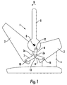
- Fig 1 illustrates a preferred embodiment of a children's safety seat 1 shown in an upright position.
- the children's safety seat 1 comprises a sitting section 2 and a back section 3.
- the sitting section 2 is fixed to a base 4.
- a carrying handle 5 for adjusting the angle between the sitting section 2 and the back section 3 is connected to the sections 2, 3 by a pivot connection 6.
- the pivot connection 6 thereby provide the pivot axis of the back section 3 and the carrying handle 5.
- a link arrangement comprising three arm links; first arm link 7, second arm link 8, and third arm link 9 is provided.
- Each arm link has a first end pivotally connected by suitable first fixing means 10, second fixing means 11 and third fixing means 12 to the back section 3, sitting section 2 and the carrying handle 5 respectively.
- the second ends of the arm links 7, 8, 9 are pivotally interconnected by suitable fourth fixing means 13.
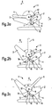
- Fig 2a shows the safety seat 1 placed in a flat/reclined position.
- the carrying handle 5 is turned in the direction towards the back section 3(illustrated by arrow B).
- This movement of the carrying handle 5 causes the third arm link 9 and the third and fourth fixing means 12, 13 to shift upwards as illustrated by the arrow A.
- the first arm link 7 is thereby made to pivot about the first and fourth fixing means 10 and 13, whereas the second arm link 8 pivots about the second and third fixing means 11 and 13.
- the back section 3 is thereby caused to pivot about the pivot connection 6 and placed with a side surface 3a abutting a side surface 2a of the sitting section 2.
- the safety seat is then brought into a reclined or flat position suitable for the support of the children's outside the vehicle.
- the angular displacement of the back section 3 is illustrated by the angle ⁇ between the sitting section 2 and the back section 3.
- Fig 2b shows the safety seat 1 placed in an upright position suitable for carrying the children's outside the vehicle.
- the carrying handle 5 is turned from the position shown in fig 2a to the upright position shown in fig 2b (illustrated by arrow D).
- the movement of the carrying handle 5 causes the third arm link 9 and the fourth fixing means 13 to shift downwards as illustrated by the arrow C, thereby transferring the shifting movement to the back section 3 via the pivoting movement of the first arm link 7 around first and fourth fixing means.
- the second arm link 8 is connected to the fixed seat section 2 and supports the transfer of movement wherein the second arm link 8 is pivoted about the second and third fixing means 11 and 13 during the transferring movement. Consequently the back section 3 is forced to pivot about the pivot connection 6, thereby bringing the side surface 3 a away from abutment with the side surface 2a, and the angle ⁇ between the sitting section 2 and the back section 3 has been changed.
- Fig 2c shows the safety seat with the carrying handle in a position wherein the safety belt is tensioned and the carrying handle provides support against the passenger seat.
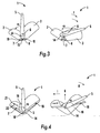
- the sitting section 2, the back section 3 and the carrying handle 5 are interconnected by a pivot joint 6.
- the sitting section 2 is fixed by suitable means(not shown), while the back section 3 is arranged to pivot about the pivot axis established by the pivot joint 6 in accordance with the turning of the carrying handle 5.
- a link arrangement comprising a first arm link 7 and a second arm link 8 is provided.
- the first link arm 7 has a first end pivotally connected to the sitting section 2 by first fixing means 10 and the second end pivotally interconnected to the second end of a second link arm 8 by third fixing means 13. Further, the first end of the second link arm 8 is pivotally connected to the back section 3 by second fixing means 11.
- the end of the carrying handle 5 is provided with a control structure 14 which is shaped as a half-circular element in fig 3.
- the control structure 14 is abutting against the link arrangement in the area where the first arm link 7 and the second arm link 8 are interconnected, exerting a holding force onto this area and keeping the first arm link 7 and the second arm link 8 in line.
- the children's safety seat 1 is arranged in the carrying position.
- the carrying handle 5 is turned about the pivot joint 6 in the direction as illustrated by the arrow F in the right illustration, the control structure is moved away from the interconnection between the first arm link 7 and the second arm link 8.
- the arm links 7, 8 are then free to rotate about the third fixing means and first and second fixing means respectively as the back section 3 pivots about the pivot joint 6 towards the sitting section 2.
- the angular displacement of the back section 3 is illustrated by the angle ⁇ between the sitting section 2 and the back section 3.
- the safety seat is brought to an inclined position by this movement. By turning the carrying handle 5 back to the upright position the children's safety seat is returned to the position as shown in left illustration.
- Fig 4 illustrates a third embodiment of the children's safety seat 1 wherein the sitting section 2 and the back section 3 is joined together by a pivot connection 18.
- the sitting section 2 and the back section 3 are displaceably connected to two frame sections,(fig 4 only illustrate one frame section 16).
- the sitting section 2 is displaceably connected to the wall element 16, by at least one sliding guidance each comprising a recess 20 and a sliding element 21, wherein at least a portion of each sliding element 21 is positioned to be moved in the recess.
- the sliding element 21 is shown fixed to or constitutes a section of the wall element 16, and the recess is provided as a part of the sitting section 2. Alternatively the sliding element may be provided as a part of the frame and the recess may be provided as a part of the seat component.
- the back section 3 is connected to the wall element 16 by a pivot joint 19.
- the illustration to the left in fig 4 shows the safety seat 1 in an upright carrying position.
- the control structure 14 shifts the pivot joint 18 upwards as illustrated by the arrow G.
- the back section 3 thereby pivots about the pivot joints 19 and 14.
- the sitting section 2 pivots about the pivot joint 18 and moves forward as illustrated by arrow I moving the sliding element 21 in the recess 20.
- Both the position of the sitting section 2 and the back section 3 is thereby changed and the children's safety seat 1 is brought into a reclined position.
- the angular displacement of the back section 3 and the sitting section 2 is illustrated by the angle ⁇ .
Abstract
Description
- The invention concerns a children's safety seat in accordance with the introductory part of the
independent claim 1. - The children's safety seat is especially suitable for small children belonging to the group 0+. The term 0+ is used to categorize children having a body weight up to 13kg.
- The children' s safety seat in accordance with the invention is provided to be used both inside the vehicle, wherein the vehicles safety seat belt may be used to fasten the safety seat in the vehicle, and outside the vehicle, wherein the children' s safety seat may be adjusted between various positions including a position suitable for carrying the children's safety seat and a reclined, flat position suitable for a resting children's.
- Prior art describe several adjustable children's safety seats such as
EP 718145 EP 157880 EP 1033280 .US 4637653 andUS 4655503 disclose adjustable seats.EP1188605 describes the use of the carrying handle to support the safety seat. - The object of the invention is to provide a solution which simplifies the adjustment of the children's safety between the various positions. This object is obtained by an inventive concept wherein the turning of the carrying handle is used to control the adjustment of the children's safety seat as defined in the characterizing part of the
independent claim 1. Further embodiments of the invention are defined in the dependent claims. - The children's safety seat in accordance with the invention comprises two seat sections. Preferably these two seat sections are constituted by a sitting section and a back section which are connected to each other. An adjustable carrying handle is connected to the safety seat and arranged to be moved between various positions relative to the children's seat. The movement of the carrying handle between the various positions causes a reposition preferably an angular displacement of at least one of the seat sections. The carrying handle is preferably pivotally connected to the children's seat by suitable means.
- In one position suitable for a baby to be carried in the children' s safety seat the carrying handle is placed upright and the corresponding arrangement of the seat sections is upright. In another position suitable for the baby to be resting for longer periods outside the vehicle the carrying handle is turned towards either of the seat sections, preferably the back section, the seat sections are then in a reclined position providing an almost flat surface for the baby to be resting outside the vehicle. When the children's safety seat is to be placed in the vehicle the carrying handle is turned towards either of the seat sections, preferably the sitting section. The corresponding arrangement of the seat sections is upright. When the children's safety seat is placed in a backward facing position in the vehicle, the carrying handle is pressed against the passenger seat of the vehicle and provides protection during a possible crash.
- In accordance with a preferred embodiment of the invention either the sitting section or the back section or both sections are arranged for angular displacement. The turning of the carrying handle causes a change in the angular arrangement of at least one of the sections. If only one of the sections is to be repositioned the other seat section is to be arranged fixed preferably to the base of the children's safety seat. The carrying handle and the two seat sections may be joined together using one pivot connection
- In accordance with a first and a second embodiment of the invention the sitting section and the back section are adjustable connected to each other, preferably the seat section is articulated connected to the back section by suitable articulating means. The articulating means may be constituted by a link arrangement of some kind.
- In the first embodiment the link arrangement comprises a first link arm, a second link arm and a third link arm. The first link arm has a first end pivotally connected to the sitting section and the first end of the second link arm is pivotally connected to the back section. The third link arm has a first end pivotally connected to the carrying handle. A connecting area between the first, second and third link arm is constituted by the second end of the first link arm, the second end of the second link arm and the second end of the third link arm being pivotally connected. The pivot connections are provided by any suitable means making the link arms able to pivot relative to each other and the seat sections. When the carrying handle is turned between the various positions the link arms in the link arrangement are rearranged and one of the seat section is subsequently displaced angularly to obtain the corresponding position of the children's safety seat. See figure description for a more detailed explanation of this embodiment.
- In the second embodiment the link arrangement comprises a first link arm and a second link arm. The first link arm has a first end pivotally connected to the sitting section and the first end of the second link arm is pivotally connected to the back section. A connecting area between the first and the second link arm is constituted by the second end of the first link arm being pivotally connected to the second end the second link arm. The pivot connections are provided by any suitable means making the link arms able to pivot relative to each other and the seat sections.
- The carrying handle is provided with a control structure, wherein the position of the control structure is determined by the position of the carrying handle. The positions of the control structure include a first position where the control structure is placed into an abutting contact with the connecting area of the first and second link arm, and a second position where the control structure is brought out of engagement with the connecting area. By bringing the control structure from one position to the other at least one of the seat sections is repositioned preferably reoriented angularly, and the children' s safety seat is brought into a different position.
- In a third embodiment of the invention the two seat sections are pivotally connected forming a connecting area. The children's safety seat is provided with a frame. One of the seat sections, preferably the sitting section is displaceably connected the frame. Thee other seat section, preferably the back section, is pivotally connected to the frame.
- The sitting section may be displaceably connected by a sliding guidance which comprises at least a recess and a least a sliding element, wherein at least a portion of each sliding element is positioned to be moved in the recess.
- In accordance with the third embodiment of the invention the carrying handle is provided with a control structure, wherein the position of the control structure is determined by the position of the carrying handle. The positions of the control structure include a first position where the control structure is placed into an abutting contact with the connecting area of the first and second seat sections, and a second position where the control structure is brought out of engagement with the connecting area. By bringing the control structure from one position to the other at the seat sections are repositioned preferably reoriented angularly, and the children's safety seat is brought into a different position.
- The children's safety seat may be provided with locking means or other arrangement to make sure that the components of the children's safety seat is held within the position chosen by the carrying handle. When changing the position of the children's safety seat the locking means must be unlocked, whereafter the new position is chosen and then children's safety seat is locked in the current position. The children's safety seat may be provided with arrangements alternative to the mentioned locking means, the children's safety seat may for instance be provided so that an automatic locking is achieved when the components of the children's safety seat in the various positions.
- The children's safety seat may be provided with indicators signalling to the user the area of use corresponding to the current position of the safety seat. Such as carrying position, sleeping position, car position.
- In the following several embodiments of the invention will be described, by way of example, with reference to accompanying drawings, in which:
- Fig 1 illustrates a side view of a first embodiment of the invention.
- Fig 2a-2c illustrates side views of the first of a first embodiment of the invention.
- Fig 3 illustrates a side view of a second embodiment of the invention.
- Fig 4 illustrates a side view of a third embodiment of the invention.
- Fig 1 illustrates a preferred embodiment of a children's
safety seat 1 shown in an upright position. The children'ssafety seat 1 comprises asitting section 2 and aback section 3. Thesitting section 2 is fixed to abase 4. Acarrying handle 5 for adjusting the angle between thesitting section 2 and theback section 3 is connected to thesections pivot connection 6. Thepivot connection 6 thereby provide the pivot axis of theback section 3 and thecarrying handle 5. In this embodiment a link arrangement comprising three arm links;first arm link 7,second arm link 8, andthird arm link 9 is provided. Each arm link has a first end pivotally connected by suitable first fixing means 10, second fixing means 11 and third fixing means 12 to theback section 3, sittingsection 2 and thecarrying handle 5 respectively. The second ends of thearm links - Fig 2a shows the
safety seat 1 placed in a flat/reclined position. Starting from fig1 the carryinghandle 5 is turned in the direction towards the back section 3(illustrated by arrow B). This movement of the carryinghandle 5 causes thethird arm link 9 and the third and fourth fixing means 12, 13 to shift upwards as illustrated by the arrow A. Thefirst arm link 7 is thereby made to pivot about the first and fourth fixing means 10 and 13, whereas thesecond arm link 8 pivots about the second and third fixing means 11 and 13. By these movements of thearm links back section 3 by first fixing means 10. Theback section 3 is thereby caused to pivot about thepivot connection 6 and placed with aside surface 3a abutting aside surface 2a of the sittingsection 2. The safety seat is then brought into a reclined or flat position suitable for the support of the children's outside the vehicle. The angular displacement of theback section 3 is illustrated by the angle α between the sittingsection 2 and theback section 3. - Fig 2b shows the
safety seat 1 placed in an upright position suitable for carrying the children's outside the vehicle. The carryinghandle 5 is turned from the position shown in fig 2a to the upright position shown in fig 2b (illustrated by arrow D). The movement of the carryinghandle 5 causes thethird arm link 9 and the fourth fixing means 13 to shift downwards as illustrated by the arrow C, thereby transferring the shifting movement to theback section 3 via the pivoting movement of thefirst arm link 7 around first and fourth fixing means. Thesecond arm link 8 is connected to the fixedseat section 2 and supports the transfer of movement wherein thesecond arm link 8 is pivoted about the second and third fixing means 11 and 13 during the transferring movement. Consequently theback section 3 is forced to pivot about thepivot connection 6, thereby bringing theside surface 3 a away from abutment with theside surface 2a, and the angle α between the sittingsection 2 and theback section 3 has been changed. - Turning the carrying handle 5 from the position shown in fig 2b (illustrated by arrow E) towards the sitting seat to the position shown in fig 2c, causes the
third arm link 9 pivot about third and fourth fixing means. During the movement of the carrying handle thethird arm link 9 is caused to shift somewhat and consequently theback section 3 also experiences a small pivoting movement preferably a movement wherein the angle α initially is increased and thereafter reduced, thereby bringing the back section into a position a little bit different from the one shown in fig 2b. Fig 2c shows the safety seat with the carrying handle in a position wherein the safety belt is tensioned and the carrying handle provides support against the passenger seat. - In the second embodiment shown in figure 3, the sitting
section 2, theback section 3 and the carryinghandle 5 are interconnected by apivot joint 6. The sittingsection 2 is fixed by suitable means(not shown), while theback section 3 is arranged to pivot about the pivot axis established by the pivot joint 6 in accordance with the turning of the carryinghandle 5. A link arrangement comprising afirst arm link 7 and asecond arm link 8 is provided. Thefirst link arm 7 has a first end pivotally connected to the sittingsection 2 by first fixing means 10 and the second end pivotally interconnected to the second end of asecond link arm 8 by third fixing means 13. Further, the first end of thesecond link arm 8 is pivotally connected to theback section 3 by second fixing means 11. The end of the carryinghandle 5 is provided with acontrol structure 14 which is shaped as a half-circular element in fig 3. When the carrying handle is arranged in an upright position as shown in the left illustration in fig 3, thecontrol structure 14 is abutting against the link arrangement in the area where thefirst arm link 7 and thesecond arm link 8 are interconnected, exerting a holding force onto this area and keeping thefirst arm link 7 and thesecond arm link 8 in line. In this position the children'ssafety seat 1 is arranged in the carrying position. When the carryinghandle 5 is turned about the pivot joint 6 in the direction as illustrated by the arrow F in the right illustration, the control structure is moved away from the interconnection between thefirst arm link 7 and thesecond arm link 8. The arm links 7, 8 are then free to rotate about the third fixing means and first and second fixing means respectively as theback section 3 pivots about the pivot joint 6 towards the sittingsection 2. The angular displacement of theback section 3 is illustrated by the angle α between the sittingsection 2 and the back section 3.The safety seat is brought to an inclined position by this movement. By turning the carryinghandle 5 back to the upright position the children's safety seat is returned to the position as shown in left illustration. - Fig 4 illustrates a third embodiment of the children's
safety seat 1 wherein the sittingsection 2 and theback section 3 is joined together by apivot connection 18. The sittingsection 2 and theback section 3 are displaceably connected to two frame sections,(fig 4 only illustrate one frame section 16). The sittingsection 2 is displaceably connected to thewall element 16, by at least one sliding guidance each comprising arecess 20 and a slidingelement 21, wherein at least a portion of each slidingelement 21 is positioned to be moved in the recess. The slidingelement 21 is shown fixed to or constitutes a section of thewall element 16, and the recess is provided as a part of the sittingsection 2. Alternatively the sliding element may be provided as a part of the frame and the recess may be provided as a part of the seat component. Theback section 3 is connected to thewall element 16 by a pivot joint 19. The illustration to the left in fig 4 shows thesafety seat 1 in an upright carrying position. When the carryinghandle 5 is turned to the position (illustrated by arrow H) shown in the right illustration shown in fig 4, thecontrol structure 14 shifts the pivot joint 18 upwards as illustrated by the arrow G. Theback section 3 thereby pivots about the pivot joints 19 and 14. The sittingsection 2 pivots about the pivot joint 18 and moves forward as illustrated by arrow I moving the slidingelement 21 in therecess 20. Both the position of the sittingsection 2 and theback section 3 is thereby changed and the children'ssafety seat 1 is brought into a reclined position. The angular displacement of theback section 3 and the sittingsection 2 is illustrated by the angle α.
Claims (12)
- Children's safety seat comprising two seat sections, preferably a sitting section and a back section, which are connected to each other and an adjustable carrying handle connected to the safety seat, which carrying handle is arranged to be moved between various positions relative to the safety seat,
characterized in that the movement of the carrying handle between the various positions causes a reposition preferably an angular displacement of at least one of the seat sections. - Children's safety seat according to claim 1 or 2,
characterized in that the carrying handle is pivotally connected to the children's seat. - Children's safety seat according to one of the proceeding claims,
characterized in that the sitting section is arranged for angular displacement and/or the back section is arranged for angular displacement. - Children's safety seat according to one of the proceeding claims,
characterized in that the two seat sections are joined together using a pivot connection and preferably that the carrying handle is connected to the same pivot connection. - Children's safety seat according to one of the proceeding claims,
characterized in that one of the seat sections is to be arranged fixed, preferably to the base of the safety seat. - Children's safety seat according to one of the proceeding claims,
characterized in that the sitting section and the back section are adjustable connected to each other, preferably the seat section is articulated connected to the back section by suitable articulating means. - Children's safety seat according to claim 6,
characterized in that the articulating means is constituted by a link arrangement comprising a first link arm having a first end pivotally connected to the sitting section and the second end pivotally connected to the second end of a second link arm forming a connecting area, the first end of the second link arm is pivotally connected to the back section. - Children's safety seat according to claim 1 or 2,
characterized in that the two seat sections are pivotally connected forming a connecting area and that a frame is provided, wherein one of the seat sections, preferably the sitting section is displaceably connected the frame and/or the other seat section, preferably the back section, is pivotally connected to the frame. - Children's safety seat according to claim 8,
characterized in that the sitting section is displaceably connected by a sliding guidance which comprises at least a recess and a least a sliding element, wherein at least a portion of each sliding element is positioned to be moved in the recess. - Children's safety seat according to one of the proceeding claims,
characterized in that thecarryinghandleisprovidedwitha control structure, wherein the position of the control structure is determined by the position of the carrying handle. - Children's safety seat according to one of the claims 7-10,
characterized in that the positions of the control structure include a first position where the control structure abuts against the connecting area and a second position where the control structure is free from the connecting area, wherein at least one of the seat sections are repositioned in these two positions preferably reoriented angularly. - Children's safety seat according to one of the claims 1-7,
characterized in that a third link arm having a first end pivotally connected to the carrying handle and the second end of the third link arm is pivotally connected to the second end of the first link arm and to the second end of a second link arm in the connecting area.
Applications Claiming Priority (1)
| Application Number | Priority Date | Filing Date | Title |
|---|---|---|---|
| GB0508854A GB2425466B (en) | 2005-04-29 | 2005-04-29 | Child seat handle with integral reclining mechanism |
Publications (3)
| Publication Number | Publication Date |
|---|---|
| EP1717095A2 true EP1717095A2 (en) | 2006-11-02 |
| EP1717095A3 EP1717095A3 (en) | 2010-03-10 |
| EP1717095B1 EP1717095B1 (en) | 2012-08-08 |
Family
ID=34674148
Family Applications (1)
| Application Number | Title | Priority Date | Filing Date |
|---|---|---|---|
| EP05256060A Not-in-force EP1717095B1 (en) | 2005-04-29 | 2005-09-28 | Reclining mechanism |
Country Status (7)
| Country | Link |
|---|---|
| US (1) | US7364232B2 (en) |
| EP (1) | EP1717095B1 (en) |
| JP (1) | JP2006305351A (en) |
| KR (1) | KR20060113549A (en) |
| CN (1) | CN1853978B (en) |
| CA (1) | CA2523384A1 (en) |
| GB (1) | GB2425466B (en) |
Cited By (3)
| Publication number | Priority date | Publication date | Assignee | Title |
|---|---|---|---|---|
| WO2019076895A1 (en) * | 2017-10-16 | 2019-04-25 | Recaro Child Safety Gmbh & Co. Kg | Baby carrier device |
| EP3628537A1 (en) * | 2014-08-29 | 2020-04-01 | CYBEX GmbH | Child seat for a motor vehicle |
| WO2021245425A1 (en) * | 2020-06-04 | 2021-12-09 | Strolleazi Group Limited | Child car seat system and child transportation system |
Families Citing this family (10)
| Publication number | Priority date | Publication date | Assignee | Title |
|---|---|---|---|---|
| US8117282B2 (en) | 2004-10-20 | 2012-02-14 | Clearplay, Inc. | Media player configured to receive playback filters from alternative storage mediums |
| US20060236220A1 (en) | 2005-04-18 | 2006-10-19 | Clearplay, Inc. | Apparatus, System and Method for Associating One or More Filter Files with a Particular Multimedia Presentation |
| GB2436520B (en) * | 2006-03-28 | 2010-06-23 | Hts Hans Torgersen & Sonn As | Reclining group |
| US20110193381A1 (en) * | 2010-02-09 | 2011-08-11 | Jose Salazar | Reclining child seat |
| DE202011000229U1 (en) * | 2011-01-31 | 2011-06-09 | Curt Würstl Vermögensverwaltungs-GmbH & Co. KG, 95032 | Baby carrier in the form of a bucket seat |
| US9162593B2 (en) | 2012-07-03 | 2015-10-20 | Kids Ii, Inc. | Infant carrier and car safety seat with no-rethread harness adjustment |
| CN106671836B (en) * | 2015-11-06 | 2020-04-03 | 宝钜儿童用品香港股份有限公司 | Adjustment mechanism and child safety seat with same |
| US10137805B1 (en) * | 2017-01-10 | 2018-11-27 | Fay McKenzie | Reclining baby car seat |
| US10737593B1 (en) | 2018-07-02 | 2020-08-11 | Summer Infant (Usa), Inc. | Car seat |
| CN109849747A (en) * | 2019-02-22 | 2019-06-07 | 好孩子儿童用品有限公司 | The safe hand basket of multifunctional children |
Citations (6)
| Publication number | Priority date | Publication date | Assignee | Title |
|---|---|---|---|---|
| US4637653A (en) | 1984-12-28 | 1987-01-20 | Toyota Jidosha Kabushiki Kaisha | Rear seat cushion in motor vehicle |
| US4655503A (en) | 1983-12-19 | 1987-04-07 | Nissan Motor Company, Ltd. | Vehicular seat |
| EP0718145A1 (en) | 1994-12-08 | 1996-06-26 | ALLEGRE PUERICULTURE HYGIENE Société Anonyme | Resting seat shell for infants |
| EP1033280A2 (en) | 1999-02-08 | 2000-09-06 | Aprica Kassai Kabushikikaisha | Juvenile safety car seat |
| EP1157880A1 (en) | 2000-05-25 | 2001-11-28 | Play, S.A. | Child seat |
| EP1188605A1 (en) | 2000-09-14 | 2002-03-20 | Play, S.A. | Infant seat |
Family Cites Families (15)
| Publication number | Priority date | Publication date | Assignee | Title |
|---|---|---|---|---|
| US4274674A (en) * | 1978-09-11 | 1981-06-23 | Baby Relax | Safety seat for transporting a child in a motor vehicle |
| GB2123686B (en) * | 1982-04-01 | 1985-08-29 | Britax Excelsior | Child safety seat |
| JPS6060268A (en) | 1983-09-13 | 1985-04-06 | Mitsubishi Electric Corp | Internal-combustion engine starting device |
| US4688850A (en) * | 1985-09-30 | 1987-08-25 | Graco Metal Products | Infant seat |
| JPH0719674Y2 (en) * | 1989-12-08 | 1995-05-10 | 住金大阪プラント株式会社 | Welding carriage support device for welding robot |
| US5143419A (en) * | 1991-09-30 | 1992-09-01 | Playskool Baby, Inc. | Collapsible infant carrier with pivot-open lock, pivot-closed lock and coaxial handle lock |
| JP2561732Y2 (en) * | 1991-12-06 | 1998-02-04 | 株式会社東海理化電機製作所 | Child seat |
| US5431478A (en) * | 1993-03-22 | 1995-07-11 | Noonan; Mark | Convertible baby carrier |
| JPH07186970A (en) * | 1993-12-27 | 1995-07-25 | Pigeon Corp | Baby carrier |
| ES1035128Y (en) * | 1996-07-15 | 1997-08-01 | Jane Sa | CHILD SEAT-CHAIR SEAT. |
| US6145927A (en) * | 1999-11-08 | 2000-11-14 | Lo; Feng-Jung | Structure of a safety baby seat |
| CN2504976Y (en) * | 2001-08-30 | 2002-08-14 | 张建军 | Chair for infants |
| US6986518B1 (en) * | 2003-12-01 | 2006-01-17 | Gary Lee Besaw | Combined baby car seat and stroller |
| DE102004020902A1 (en) * | 2004-04-28 | 2005-12-01 | Recaro Gmbh & Co. Kg | Baby Seat |
| US7037205B1 (en) * | 2004-09-01 | 2006-05-02 | Jeffrey Alan Bowman | Baby carrier having an integral swinging mechanism |
-
2005
- 2005-04-29 GB GB0508854A patent/GB2425466B/en not_active Expired - Fee Related
- 2005-09-28 EP EP05256060A patent/EP1717095B1/en not_active Not-in-force
- 2005-10-11 US US11/246,169 patent/US7364232B2/en not_active Expired - Fee Related
- 2005-10-12 CA CA002523384A patent/CA2523384A1/en not_active Abandoned
-
2006
- 2006-04-20 JP JP2006116978A patent/JP2006305351A/en not_active Ceased
- 2006-04-27 CN CN2006100766393A patent/CN1853978B/en not_active Expired - Fee Related
- 2006-04-28 KR KR1020060038909A patent/KR20060113549A/en not_active Application Discontinuation
Patent Citations (6)
| Publication number | Priority date | Publication date | Assignee | Title |
|---|---|---|---|---|
| US4655503A (en) | 1983-12-19 | 1987-04-07 | Nissan Motor Company, Ltd. | Vehicular seat |
| US4637653A (en) | 1984-12-28 | 1987-01-20 | Toyota Jidosha Kabushiki Kaisha | Rear seat cushion in motor vehicle |
| EP0718145A1 (en) | 1994-12-08 | 1996-06-26 | ALLEGRE PUERICULTURE HYGIENE Société Anonyme | Resting seat shell for infants |
| EP1033280A2 (en) | 1999-02-08 | 2000-09-06 | Aprica Kassai Kabushikikaisha | Juvenile safety car seat |
| EP1157880A1 (en) | 2000-05-25 | 2001-11-28 | Play, S.A. | Child seat |
| EP1188605A1 (en) | 2000-09-14 | 2002-03-20 | Play, S.A. | Infant seat |
Cited By (3)
| Publication number | Priority date | Publication date | Assignee | Title |
|---|---|---|---|---|
| EP3628537A1 (en) * | 2014-08-29 | 2020-04-01 | CYBEX GmbH | Child seat for a motor vehicle |
| WO2019076895A1 (en) * | 2017-10-16 | 2019-04-25 | Recaro Child Safety Gmbh & Co. Kg | Baby carrier device |
| WO2021245425A1 (en) * | 2020-06-04 | 2021-12-09 | Strolleazi Group Limited | Child car seat system and child transportation system |
Also Published As
| Publication number | Publication date |
|---|---|
| US7364232B2 (en) | 2008-04-29 |
| KR20060113549A (en) | 2006-11-02 |
| EP1717095A3 (en) | 2010-03-10 |
| US20060267388A1 (en) | 2006-11-30 |
| JP2006305351A (en) | 2006-11-09 |
| GB2425466B (en) | 2008-11-26 |
| CN1853978B (en) | 2013-05-22 |
| EP1717095B1 (en) | 2012-08-08 |
| GB0508854D0 (en) | 2005-06-08 |
| CA2523384A1 (en) | 2006-10-29 |
| CN1853978A (en) | 2006-11-01 |
| GB2425466A (en) | 2006-11-01 |
Similar Documents
| Publication | Publication Date | Title |
|---|---|---|
| EP1717095B1 (en) | Reclining mechanism | |
| CA2552379C (en) | Chair with tilt lock mechanism | |
| JP5276261B2 (en) | Car seat with seat, backrest and underframe | |
| KR960012613B1 (en) | Safety seat of automobile for children | |
| JP2784351B2 (en) | Automobile seat structure that can take a variable shape | |
| US4792181A (en) | Foldable armchair with adjustable backrest and footrest | |
| JP2008030658A (en) | Vehicle seat device | |
| KR101547105B1 (en) | Vehicle seat, in particular motor vehicle seat | |
| EP0079809B1 (en) | Pivotal adjustment mechanism | |
| JP2010535123A (en) | Vehicle seats for cars | |
| EP1937509A2 (en) | Child safety seat | |
| CN114643914A (en) | Vehicle seat with backrest | |
| CN100567045C (en) | Collapsible vehicle seat | |
| JP2519874B2 (en) | Car bucket seat | |
| JP3137175B2 (en) | Vehicle seat | |
| JP2891290B2 (en) | Vehicle seat | |
| KR100209021B1 (en) | Swivel system of a car's seat | |
| JP3269071B2 (en) | Vehicle seat | |
| JPH08175394A (en) | Seat of stroller | |
| JPH03114409A (en) | Seat with backrest capable of adjustment and inclination | |
| JP2658774B2 (en) | Turning type seat | |
| JP2891289B2 (en) | Vehicle seat | |
| KR200230974Y1 (en) | Slider of a seat for the car | |
| JPH09109741A (en) | Seat for vehicle | |
| JP3209400B2 (en) | Vehicle seat |
Legal Events
| Date | Code | Title | Description |
|---|---|---|---|
| PUAI | Public reference made under article 153(3) epc to a published international application that has entered the european phase |
Free format text: ORIGINAL CODE: 0009012 |
|
| 17P | Request for examination filed |
Effective date: 20060407 |
|
| AK | Designated contracting states |
Kind code of ref document: A2 Designated state(s): AT BE BG CH CY CZ DE DK EE ES FI FR GB GR HU IE IS IT LI LT LU LV MC NL PL PT RO SE SI SK TR |
|
| AX | Request for extension of the european patent |
Extension state: AL BA HR MK YU |
|
| PUAL | Search report despatched |
Free format text: ORIGINAL CODE: 0009013 |
|
| AK | Designated contracting states |
Kind code of ref document: A3 Designated state(s): AT BE BG CH CY CZ DE DK EE ES FI FR GB GR HU IE IS IT LI LT LU LV MC NL PL PT RO SE SI SK TR |
|
| AX | Request for extension of the european patent |
Extension state: AL BA HR MK YU |
|
| AKX | Designation fees paid |
Designated state(s): AT BE BG CH CY CZ DE DK EE ES FI FR GB GR HU IE IS IT LI LT LU LV MC NL PL PT RO SE SI SK TR |
|
| 17Q | First examination report despatched |
Effective date: 20110606 |
|
| GRAP | Despatch of communication of intention to grant a patent |
Free format text: ORIGINAL CODE: EPIDOSNIGR1 |
|
| GRAS | Grant fee paid |
Free format text: ORIGINAL CODE: EPIDOSNIGR3 |
|
| GRAA | (expected) grant |
Free format text: ORIGINAL CODE: 0009210 |
|
| STAA | Information on the status of an ep patent application or granted ep patent |
Free format text: STATUS: THE PATENT HAS BEEN GRANTED |
|
| AK | Designated contracting states |
Kind code of ref document: B1 Designated state(s): AT BE BG CH CY CZ DE DK EE ES FI FR GB GR HU IE IS IT LI LT LU LV MC NL PL PT RO SE SI SK TR |
|
| REG | Reference to a national code |
Ref country code: GB Ref legal event code: FG4D |
|
| REG | Reference to a national code |
Ref country code: CH Ref legal event code: EP Ref country code: AT Ref legal event code: REF Ref document number: 569567 Country of ref document: AT Kind code of ref document: T Effective date: 20120815 |
|
| REG | Reference to a national code |
Ref country code: IE Ref legal event code: FG4D |
|
| REG | Reference to a national code |
Ref country code: DE Ref legal event code: R096 Ref document number: 602005035499 Country of ref document: DE Effective date: 20121011 |
|
| PGFP | Annual fee paid to national office [announced via postgrant information from national office to epo] |
Ref country code: IE Payment date: 20120928 Year of fee payment: 8 |
|
| REG | Reference to a national code |
Ref country code: NL Ref legal event code: VDEP Effective date: 20120808 |
|
| REG | Reference to a national code |
Ref country code: AT Ref legal event code: MK05 Ref document number: 569567 Country of ref document: AT Kind code of ref document: T Effective date: 20120808 |
|
| REG | Reference to a national code |
Ref country code: LT Ref legal event code: MG4D Effective date: 20120808 |
|
| PG25 | Lapsed in a contracting state [announced via postgrant information from national office to epo] |
Ref country code: CY Free format text: LAPSE BECAUSE OF FAILURE TO SUBMIT A TRANSLATION OF THE DESCRIPTION OR TO PAY THE FEE WITHIN THE PRESCRIBED TIME-LIMIT Effective date: 20120808 Ref country code: LT Free format text: LAPSE BECAUSE OF FAILURE TO SUBMIT A TRANSLATION OF THE DESCRIPTION OR TO PAY THE FEE WITHIN THE PRESCRIBED TIME-LIMIT Effective date: 20120808 Ref country code: FI Free format text: LAPSE BECAUSE OF FAILURE TO SUBMIT A TRANSLATION OF THE DESCRIPTION OR TO PAY THE FEE WITHIN THE PRESCRIBED TIME-LIMIT Effective date: 20120808 Ref country code: AT Free format text: LAPSE BECAUSE OF FAILURE TO SUBMIT A TRANSLATION OF THE DESCRIPTION OR TO PAY THE FEE WITHIN THE PRESCRIBED TIME-LIMIT Effective date: 20120808 Ref country code: IS Free format text: LAPSE BECAUSE OF FAILURE TO SUBMIT A TRANSLATION OF THE DESCRIPTION OR TO PAY THE FEE WITHIN THE PRESCRIBED TIME-LIMIT Effective date: 20121208 |
|
| PG25 | Lapsed in a contracting state [announced via postgrant information from national office to epo] |
Ref country code: SE Free format text: LAPSE BECAUSE OF FAILURE TO SUBMIT A TRANSLATION OF THE DESCRIPTION OR TO PAY THE FEE WITHIN THE PRESCRIBED TIME-LIMIT Effective date: 20120808 Ref country code: LV Free format text: LAPSE BECAUSE OF FAILURE TO SUBMIT A TRANSLATION OF THE DESCRIPTION OR TO PAY THE FEE WITHIN THE PRESCRIBED TIME-LIMIT Effective date: 20120808 Ref country code: SI Free format text: LAPSE BECAUSE OF FAILURE TO SUBMIT A TRANSLATION OF THE DESCRIPTION OR TO PAY THE FEE WITHIN THE PRESCRIBED TIME-LIMIT Effective date: 20120808 Ref country code: PL Free format text: LAPSE BECAUSE OF FAILURE TO SUBMIT A TRANSLATION OF THE DESCRIPTION OR TO PAY THE FEE WITHIN THE PRESCRIBED TIME-LIMIT Effective date: 20120808 Ref country code: PT Free format text: LAPSE BECAUSE OF FAILURE TO SUBMIT A TRANSLATION OF THE DESCRIPTION OR TO PAY THE FEE WITHIN THE PRESCRIBED TIME-LIMIT Effective date: 20121210 Ref country code: GR Free format text: LAPSE BECAUSE OF FAILURE TO SUBMIT A TRANSLATION OF THE DESCRIPTION OR TO PAY THE FEE WITHIN THE PRESCRIBED TIME-LIMIT Effective date: 20121109 Ref country code: BE Free format text: LAPSE BECAUSE OF FAILURE TO SUBMIT A TRANSLATION OF THE DESCRIPTION OR TO PAY THE FEE WITHIN THE PRESCRIBED TIME-LIMIT Effective date: 20120808 |
|
| PG25 | Lapsed in a contracting state [announced via postgrant information from national office to epo] |
Ref country code: NL Free format text: LAPSE BECAUSE OF FAILURE TO SUBMIT A TRANSLATION OF THE DESCRIPTION OR TO PAY THE FEE WITHIN THE PRESCRIBED TIME-LIMIT Effective date: 20120808 |
|
| PG25 | Lapsed in a contracting state [announced via postgrant information from national office to epo] |
Ref country code: DK Free format text: LAPSE BECAUSE OF FAILURE TO SUBMIT A TRANSLATION OF THE DESCRIPTION OR TO PAY THE FEE WITHIN THE PRESCRIBED TIME-LIMIT Effective date: 20120808 Ref country code: RO Free format text: LAPSE BECAUSE OF FAILURE TO SUBMIT A TRANSLATION OF THE DESCRIPTION OR TO PAY THE FEE WITHIN THE PRESCRIBED TIME-LIMIT Effective date: 20120808 Ref country code: CZ Free format text: LAPSE BECAUSE OF FAILURE TO SUBMIT A TRANSLATION OF THE DESCRIPTION OR TO PAY THE FEE WITHIN THE PRESCRIBED TIME-LIMIT Effective date: 20120808 Ref country code: EE Free format text: LAPSE BECAUSE OF FAILURE TO SUBMIT A TRANSLATION OF THE DESCRIPTION OR TO PAY THE FEE WITHIN THE PRESCRIBED TIME-LIMIT Effective date: 20120808 Ref country code: MC Free format text: LAPSE BECAUSE OF NON-PAYMENT OF DUE FEES Effective date: 20120930 Ref country code: ES Free format text: LAPSE BECAUSE OF FAILURE TO SUBMIT A TRANSLATION OF THE DESCRIPTION OR TO PAY THE FEE WITHIN THE PRESCRIBED TIME-LIMIT Effective date: 20121119 |
|
| REG | Reference to a national code |
Ref country code: CH Ref legal event code: PL |
|
| PG25 | Lapsed in a contracting state [announced via postgrant information from national office to epo] |
Ref country code: SK Free format text: LAPSE BECAUSE OF FAILURE TO SUBMIT A TRANSLATION OF THE DESCRIPTION OR TO PAY THE FEE WITHIN THE PRESCRIBED TIME-LIMIT Effective date: 20120808 |
|
| PLBE | No opposition filed within time limit |
Free format text: ORIGINAL CODE: 0009261 |
|
| STAA | Information on the status of an ep patent application or granted ep patent |
Free format text: STATUS: NO OPPOSITION FILED WITHIN TIME LIMIT |
|
| 26N | No opposition filed |
Effective date: 20130510 |
|
| GBPC | Gb: european patent ceased through non-payment of renewal fee |
Effective date: 20121108 |
|
| PG25 | Lapsed in a contracting state [announced via postgrant information from national office to epo] |
Ref country code: BG Free format text: LAPSE BECAUSE OF FAILURE TO SUBMIT A TRANSLATION OF THE DESCRIPTION OR TO PAY THE FEE WITHIN THE PRESCRIBED TIME-LIMIT Effective date: 20121108 Ref country code: LI Free format text: LAPSE BECAUSE OF NON-PAYMENT OF DUE FEES Effective date: 20120930 Ref country code: CH Free format text: LAPSE BECAUSE OF NON-PAYMENT OF DUE FEES Effective date: 20120930 |
|
| REG | Reference to a national code |
Ref country code: DE Ref legal event code: R097 Ref document number: 602005035499 Country of ref document: DE Effective date: 20130510 |
|
| PG25 | Lapsed in a contracting state [announced via postgrant information from national office to epo] |
Ref country code: GB Free format text: LAPSE BECAUSE OF NON-PAYMENT OF DUE FEES Effective date: 20121108 |
|
| PG25 | Lapsed in a contracting state [announced via postgrant information from national office to epo] |
Ref country code: TR Free format text: LAPSE BECAUSE OF FAILURE TO SUBMIT A TRANSLATION OF THE DESCRIPTION OR TO PAY THE FEE WITHIN THE PRESCRIBED TIME-LIMIT Effective date: 20120808 |
|
| PG25 | Lapsed in a contracting state [announced via postgrant information from national office to epo] |
Ref country code: LU Free format text: LAPSE BECAUSE OF NON-PAYMENT OF DUE FEES Effective date: 20120928 |
|
| REG | Reference to a national code |
Ref country code: IE Ref legal event code: MM4A |
|
| PG25 | Lapsed in a contracting state [announced via postgrant information from national office to epo] |
Ref country code: HU Free format text: LAPSE BECAUSE OF FAILURE TO SUBMIT A TRANSLATION OF THE DESCRIPTION OR TO PAY THE FEE WITHIN THE PRESCRIBED TIME-LIMIT Effective date: 20050928 Ref country code: IE Free format text: LAPSE BECAUSE OF NON-PAYMENT OF DUE FEES Effective date: 20130928 |
|
| REG | Reference to a national code |
Ref country code: FR Ref legal event code: PLFP Year of fee payment: 10 |
|
| PGFP | Annual fee paid to national office [announced via postgrant information from national office to epo] |
Ref country code: DE Payment date: 20150310 Year of fee payment: 10 Ref country code: IT Payment date: 20150324 Year of fee payment: 10 |
|
| PGFP | Annual fee paid to national office [announced via postgrant information from national office to epo] |
Ref country code: FR Payment date: 20150310 Year of fee payment: 10 |
|
| REG | Reference to a national code |
Ref country code: DE Ref legal event code: R119 Ref document number: 602005035499 Country of ref document: DE |
|
| PG25 | Lapsed in a contracting state [announced via postgrant information from national office to epo] |
Ref country code: IT Free format text: LAPSE BECAUSE OF NON-PAYMENT OF DUE FEES Effective date: 20150928 |
|
| REG | Reference to a national code |
Ref country code: FR Ref legal event code: ST Effective date: 20160531 |
|
| PG25 | Lapsed in a contracting state [announced via postgrant information from national office to epo] |
Ref country code: DE Free format text: LAPSE BECAUSE OF NON-PAYMENT OF DUE FEES Effective date: 20160401 |
|
| PG25 | Lapsed in a contracting state [announced via postgrant information from national office to epo] |
Ref country code: FR Free format text: LAPSE BECAUSE OF NON-PAYMENT OF DUE FEES Effective date: 20150930 |