EP1716987A1 - Fence arrangement for a miter saw - Google Patents
Fence arrangement for a miter saw Download PDFInfo
- Publication number
- EP1716987A1 EP1716987A1 EP20060112535 EP06112535A EP1716987A1 EP 1716987 A1 EP1716987 A1 EP 1716987A1 EP 20060112535 EP20060112535 EP 20060112535 EP 06112535 A EP06112535 A EP 06112535A EP 1716987 A1 EP1716987 A1 EP 1716987A1
- Authority
- EP
- European Patent Office
- Prior art keywords
- fence
- miter saw
- saw
- attached
- fixed fence
- Prior art date
- Legal status (The legal status is an assumption and is not a legal conclusion. Google has not performed a legal analysis and makes no representation as to the accuracy of the status listed.)
- Granted
Links
Images

Classifications
-
- B—PERFORMING OPERATIONS; TRANSPORTING
- B23—MACHINE TOOLS; METAL-WORKING NOT OTHERWISE PROVIDED FOR
- B23D—PLANING; SLOTTING; SHEARING; BROACHING; SAWING; FILING; SCRAPING; LIKE OPERATIONS FOR WORKING METAL BY REMOVING MATERIAL, NOT OTHERWISE PROVIDED FOR
- B23D45/00—Sawing machines or sawing devices with circular saw blades or with friction saw discs
- B23D45/04—Sawing machines or sawing devices with circular saw blades or with friction saw discs with a circular saw blade or the stock carried by a pivoted lever
- B23D45/042—Sawing machines or sawing devices with circular saw blades or with friction saw discs with a circular saw blade or the stock carried by a pivoted lever with the saw blade carried by a pivoted lever
- B23D45/046—Sawing machines or sawing devices with circular saw blades or with friction saw discs with a circular saw blade or the stock carried by a pivoted lever with the saw blade carried by a pivoted lever the pivoted lever being mounted on a carriage
- B23D45/048—Sawing machines or sawing devices with circular saw blades or with friction saw discs with a circular saw blade or the stock carried by a pivoted lever with the saw blade carried by a pivoted lever the pivoted lever being mounted on a carriage the saw blade being adjustable according to angle of cut
-
- B—PERFORMING OPERATIONS; TRANSPORTING
- B23—MACHINE TOOLS; METAL-WORKING NOT OTHERWISE PROVIDED FOR
- B23D—PLANING; SLOTTING; SHEARING; BROACHING; SAWING; FILING; SCRAPING; LIKE OPERATIONS FOR WORKING METAL BY REMOVING MATERIAL, NOT OTHERWISE PROVIDED FOR
- B23D47/00—Sawing machines or sawing devices working with circular saw blades, characterised only by constructional features of particular parts
- B23D47/132—Sawing machines or sawing devices working with circular saw blades, characterised only by constructional features of particular parts of means to position the saw blade at a specified angle when adjusting about an axis perpendicular to the work support surface
-
- B—PERFORMING OPERATIONS; TRANSPORTING
- B27—WORKING OR PRESERVING WOOD OR SIMILAR MATERIAL; NAILING OR STAPLING MACHINES IN GENERAL
- B27B—SAWS FOR WOOD OR SIMILAR MATERIAL; COMPONENTS OR ACCESSORIES THEREFOR
- B27B27/00—Guide fences or stops for timber in saw mills or sawing machines; Measuring equipment thereon
- B27B27/04—Guide fences or stops for timber in saw mills or sawing machines; Measuring equipment thereon arranged perpendicularly to the plane of the saw blade
-
- B—PERFORMING OPERATIONS; TRANSPORTING
- B27—WORKING OR PRESERVING WOOD OR SIMILAR MATERIAL; NAILING OR STAPLING MACHINES IN GENERAL
- B27B—SAWS FOR WOOD OR SIMILAR MATERIAL; COMPONENTS OR ACCESSORIES THEREFOR
- B27B27/00—Guide fences or stops for timber in saw mills or sawing machines; Measuring equipment thereon
- B27B27/08—Guide fences or stops for timber in saw mills or sawing machines; Measuring equipment thereon arranged adjustably, not limited to only one of the groups B27B27/02 - B27B27/06
-
- Y—GENERAL TAGGING OF NEW TECHNOLOGICAL DEVELOPMENTS; GENERAL TAGGING OF CROSS-SECTIONAL TECHNOLOGIES SPANNING OVER SEVERAL SECTIONS OF THE IPC; TECHNICAL SUBJECTS COVERED BY FORMER USPC CROSS-REFERENCE ART COLLECTIONS [XRACs] AND DIGESTS
- Y10—TECHNICAL SUBJECTS COVERED BY FORMER USPC
- Y10T—TECHNICAL SUBJECTS COVERED BY FORMER US CLASSIFICATION
- Y10T83/00—Cutting
- Y10T83/768—Rotatable disc tool pair or tool and carrier
- Y10T83/7755—Carrier for rotatable tool movable during cutting
- Y10T83/7788—Tool carrier oscillated or rotated
Definitions
- This invention relates generally to miter saws and specifically to fence arrangements for miter saws.
- the fences may include a fixed portion and a slidable portion slidably disposed on the fixed portion, as disclosed in US Patent Nos. 5,297,463 and 5,943,931 .
- an improved miter saw is employed.
- the miter saw includes a base having a first substantially horizontal surface for supporting a workpiece and a second substantially horizontal surface disposed below the first surface, a table rotatably attached to the base, the table being substantially coplanar with the first surface, a saw assembly movable between a front position and a rear position, the saw assembly comprising a trunnion, a pivot arm pivotally attached to the trunnion, an upper blade guard connected to the pivot arm, a motor attached to the upper blade guard, and a blade driven by the motor, and a fence assembly attached to the base, the fence assembly comprising a fixed fence disposed on the second surface and fixedly attached to the base.
- slide miter saws 10 have a base 11, a rotatable table 12 attached to the base 11, and a saw assembly which comprises a trunnion 16, a pivot arm 17A pivotably attached to trunnion 16, a motor 20, a blade 19 driven by the motor 20, an upper blade guard 17 for covering an upper part of blade 19, and a lower blade 18 pivotally attached to the upper blade guard 17 for covering a lower part of blade 19.
- Motor 20 is typically attached to the upper blade guard 17.
- the slide miter saws 10 may also have a movable fence assembly 20 attached to the base 11.
- Movable fence assembly 20 preferably extends laterally across table 12, against which a workpiece can be positioned and supported for performing a cutting operation thereon.
- Movable fence assembly 20 preferably includes a fixed fence 21 attached to base 11, and a movable fence 22 connected to the fixed fence 21.
- Movable fence 22 may be slidably attached to fixed fence 21.
- Persons skilled in the art are referred to US Patent Nos. 5,297,463 and 5,943,931 for further information on such movable fence assemblies, which are wholly incorporated by reference herein.
- Slide miter saws 10 may also have a mechanism to enable the user to move the saw assembly horizontally along the table 12. Referring to FIG. 1, slide miter saw 10 accomplish this by connecting the saw assembly to at least one rail 15, which is slidably attached to a support housing 14 connected to the table 11 (see, e.g., US Patent No. 6,067,885 , incorporated herein by reference).
- At least one rail 15 may be slidably connected to table 12, as shown in FIG. 2.
- Support housing 14 is then fixedly attached to the rail(s) 15.
- support housing 14 is attached to trunnion 16. See, e.g., US Patent No. 5,054,352 , which is incorporated herein by reference.
- the user would pull the saw assembly forwardly, move the saw assembly downwardly, then push the saw assembly rearwardly for cutting the workpiece.
- movable fence 22 and/or fixed fence 21 define a fence plane FP for supporting a workpiece.
- fixed fence 21 and movable fence 22 are substantially coplanar.
- Fence plane FP is preferably substantially vertical.
- base 11 and/or table 12 define a horizontal plane HP for supporting the workpiece.
- base 11 and table 12 are substantially coplanar.
- base 11 preferably defines a second horizontal plane HP2, disposed below horizontal plane HP.
- a shoulder 11S may be disposed between horizontal planes HP, HP2.
- Fixed fence 21 is preferably disposed on the second horizontal plane HP2 and/or against shoulder 11S. At least one screw 21S may be used to affix fixed fence 21 to base 11. Screw(s) 21 S are preferably countersunk into fixed fence 21.
- FIG. 4 illustrates a second embodiment of movable fence assembly 20, where like numerals refer to like parts.
- fixed fence 21 may have a downwardly-extending flange 21F.
- flange 21F extends substantially vertically and contacts base 11 along a substantially vertical plane VP and/or a horizontal plane HP3.
- At least one screw 21S may extend through flange 21F and threadingly engage base 11.
- movable fence 22 may be slidably disposed on fixed fence 21.
- movable fence 22 has a downwardly-extending protrusion 22P extending into a channel 21C formed by fixed fence 21.
- the user can move movable fence 22 along fixed fence 21.
- the user In order to lock the position of movable fence 22 relative to fixed fence 21, the user would rotate a lock screw 23, which pushes protrusion 22P into locking contact with fixed fence 21.
- the longitudinal axis of screw 23 may be inclined relative to horizontal plane HP and/or fence plane FP.
- the angle A between the longitudinal axis of screw 23 and horizontal plane HP may be between about 5 degrees and about 25 degrees. Preferably, angle A is about 10 degrees.
- a channel 22C is created in protrusion 22P.
- a set screw 24 may be disposed in fixed fence 21 and extend into channel 22C. Persons skilled in the art will recognize that set screw 24 may be replaced by a protrusion in fixed fence 21. With such arrangement, movable fence 22 may not be removed from fixed fence 21 by lifting movable fence 22 vertically.
Landscapes
- Engineering & Computer Science (AREA)
- Mechanical Engineering (AREA)
- Life Sciences & Earth Sciences (AREA)
- Wood Science & Technology (AREA)
- Forests & Forestry (AREA)
- Sawing (AREA)
Abstract
Description
- This application derives priority from
US Application No. 60/674,634, filed April 25, 2005 - This invention relates generally to miter saws and specifically to fence arrangements for miter saws.
- It is well known to provide fences on miter saws for supporting a workpiece disposed thereagainst. The fences may include a fixed portion and a slidable portion slidably disposed on the fixed portion, as disclosed in
US Patent Nos. 5,297,463 and5,943,931 . - It is desirable to improve such fences.
- In accordance with the present invention, an improved miter saw is employed. The miter saw includes a base having a first substantially horizontal surface for supporting a workpiece and a second substantially horizontal surface disposed below the first surface, a table rotatably attached to the base, the table being substantially coplanar with the first surface, a saw assembly movable between a front position and a rear position, the saw assembly comprising a trunnion, a pivot arm pivotally attached to the trunnion, an upper blade guard connected to the pivot arm, a motor attached to the upper blade guard, and a blade driven by the motor, and a fence assembly attached to the base, the fence assembly comprising a fixed fence disposed on the second surface and fixedly attached to the base.
- Additional features and benefits of the present invention are described, and will be apparent from, the accompanying drawings and the detailed description below.
- The accompanying drawings illustrate preferred embodiments of the invention according to the practical application of the principles thereof, and in which:
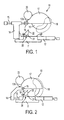
- FIG. 1 is a side view of a first slide miter saw;
- FIG. 2 is a side view of a second slide miter saw;
- FIG. 3 is a side view of a first embodiment of the fence arrangement according to the invention; and
- FIG. 4 is a partial side view of a second embodiment of the fence arrangement according to the invention.
- The invention is now described with reference to the accompanying figures, wherein like numerals designate like parts. The present invention can be incorporated into miter saws, chop saws, compound miter saws, slide miter saws, etc. For the sake of convenience, the present invention will be described as applied to a slide miter saw. Nonetheless, persons skilled in the art shall recognize the applicability of the present invention to other power tools.
- Referring to FIGS. 1-2,
slide miter saws 10 have abase 11, a rotatable table 12 attached to thebase 11, and a saw assembly which comprises atrunnion 16, apivot arm 17A pivotably attached totrunnion 16, amotor 20, ablade 19 driven by themotor 20, anupper blade guard 17 for covering an upper part ofblade 19, and alower blade 18 pivotally attached to theupper blade guard 17 for covering a lower part ofblade 19.Motor 20 is typically attached to theupper blade guard 17. - The
slide miter saws 10 may also have amovable fence assembly 20 attached to thebase 11.Movable fence assembly 20 preferably extends laterally across table 12, against which a workpiece can be positioned and supported for performing a cutting operation thereon.Movable fence assembly 20 preferably includes afixed fence 21 attached tobase 11, and amovable fence 22 connected to the fixedfence 21.Movable fence 22 may be slidably attached to fixedfence 21. Persons skilled in the art are referred toUS Patent Nos. 5,297,463 and5,943,931 for further information on such movable fence assemblies, which are wholly incorporated by reference herein. -
Slide miter saws 10 may also have a mechanism to enable the user to move the saw assembly horizontally along the table 12. Referring to FIG. 1, slide miter saw 10 accomplish this by connecting the saw assembly to at least onerail 15, which is slidably attached to asupport housing 14 connected to the table 11 (see, e.g.,US Patent No. 6,067,885 , incorporated herein by reference). - Alternatively, at least one
rail 15 may be slidably connected to table 12, as shown in FIG. 2.Support housing 14 is then fixedly attached to the rail(s) 15. In addition,support housing 14 is attached totrunnion 16. See, e.g.,US Patent No. 5,054,352 , which is incorporated herein by reference. - Another arrangement is disclosed in
US Patent No. 5,862,732 , which is wholly incorporated herein by reference, whererail 15 is fixedly attached to table 12, and support housing 14 (and the saw assembly) slide alongrail 15. - With such arrangements, the user would pull the saw assembly forwardly, move the saw assembly downwardly, then push the saw assembly rearwardly for cutting the workpiece.
- Referring to FIGS. 1-3,
movable fence 22 and/or fixedfence 21 define a fence plane FP for supporting a workpiece. Preferably, fixedfence 21 andmovable fence 22 are substantially coplanar. Fence plane FP is preferably substantially vertical. - In addition,
base 11 and/or table 12 define a horizontal plane HP for supporting the workpiece. Preferably,base 11 and table 12 are substantially coplanar. - Referring to FIG. 3,
base 11 preferably defines a second horizontal plane HP2, disposed below horizontal plane HP. Ashoulder 11S may be disposed between horizontal planes HP, HP2. Fixedfence 21 is preferably disposed on the second horizontal plane HP2 and/or againstshoulder 11S. At least onescrew 21S may be used to affixfixed fence 21 tobase 11. Screw(s) 21 S are preferably countersunk into fixedfence 21. - Persons skilled in the art will recognize that screw(s) 21S in FIG. 3 have a substantially vertical axis. FIG. 4 illustrates a second embodiment of
movable fence assembly 20, where like numerals refer to like parts. The only major difference between the first and second embodiments is thatfixed fence 21 may have a downwardly-extendingflange 21F. Preferablyflange 21F extends substantially vertically andcontacts base 11 along a substantially vertical plane VP and/or a horizontal plane HP3. At least onescrew 21S may extend throughflange 21F and threadingly engagebase 11. - Referring to FIG. 3,
movable fence 22 may be slidably disposed on fixedfence 21. Preferably,movable fence 22 has a downwardly-extendingprotrusion 22P extending into achannel 21C formed byfixed fence 21. - The user can move
movable fence 22 along fixedfence 21. In order to lock the position ofmovable fence 22 relative to fixedfence 21, the user would rotate alock screw 23, which pushesprotrusion 22P into locking contact with fixedfence 21. - The longitudinal axis of
screw 23 may be inclined relative to horizontal plane HP and/or fence plane FP. The angle A between the longitudinal axis ofscrew 23 and horizontal plane HP may be between about 5 degrees and about 25 degrees. Preferably, angle A is about 10 degrees. - Preferably a
channel 22C is created inprotrusion 22P. Aset screw 24 may be disposed in fixedfence 21 and extend intochannel 22C. Persons skilled in the art will recognize that setscrew 24 may be replaced by a protrusion in fixedfence 21. With such arrangement,movable fence 22 may not be removed from fixedfence 21 by liftingmovable fence 22 vertically. - Persons skilled in the art may recognize other additions or alternatives to the means disclosed herein. However, all these additions and/or alterations are considered to be equivalents of the present invention.
Claims (18)
- A miter saw comprising:a base having a first substantially horizontal surface for supporting a workpiece and a second substantially horizontal surface disposed below the first surface;a table rotatably attached to the base, the table being substantially coplanar with the first surface;a saw assembly pivotably attached to the table, the saw assembly comprising a motor, and a blade driven by the motor; anda fence assembly attached to the base, the fence assembly comprising a fixed fence disposed on the second surface and fixedly attached to the base.
- The miter saw of Claim 1, wherein the saw assembly further comprises a trunnion, a pivot arm pivotally attached to the trunnion, and an upper blade guard connected to the pivot arm.
- The miter saw of Claim 2, wherein the motor is attached to the upper blade guard.
- The miter saw of Claim 2, wherein the trunnion is attached to at least one rail slidingly connected to the table.
- The miter saw of Claim 1, wherein the saw assembly further comprises a trunnion pivotally attached to the table, at least one rail slidingly connected to the trunnion, a pivot arm pivotally attached to the at least one rail, and an upper blade guard connected to the pivot arm.
- The miter saw of Claim 5, wherein the motor is attached to the upper blade guard.
- The miter saw of Claim 1, further comprising a movable fence disposed on fixed fence that is movable relative to the fixed fence.
- The miter saw of Claim 7, wherein the movable fence slides relative to the fixed fence.
- The miter saw of Claim 7, wherein the movable fence has a first substantially vertical workpiece-supporting plane.
- The miter saw of Claim 9, wherein the fixed fence has a second substantially vertical workpiece-supporting plane that is substantially coplanar with the first workpiece-supporting plane.
- The miter saw of Claim 7, wherein the movable fence is lockable in position relative to the fixed fence by a screw.
- The miter saw of Claim 11, wherein the screw is inclined relative to at least one of the first workpiece-supporting plane and the first substantially horizontal surface.
- The miter saw of Claim 12, wherein the screw is inclined relative to the first substantially horizontal surface at an angle between about 5 degrees and about 25 degrees.
- The miter saw of Claim 7, wherein the movable fence has a downwardly-extending protrusion received within a channel of the fixed fence.
- The miter saw of Claim 14, wherein a fixed fence protrusion extends from the fixed fence and into the channel, so that the fixed fence protrusion is disposed above the protrusion of the movable fence.
- The miter saw of Claim 15, wherein the fixed fence protrusion is a set screw.
- The miter saw Claim 1, wherein the fixed fence has a downwardly-extending protrusion that contacts a substantially vertical surface of the base.
- The miter saw of Claim 17, wherein a screw extends through the downwardly-extending protrusion of the fixed fence and threadingly engages the base.
Applications Claiming Priority (1)
| Application Number | Priority Date | Filing Date | Title |
|---|---|---|---|
| US67463405P | 2005-04-25 | 2005-04-25 |
Publications (2)
| Publication Number | Publication Date |
|---|---|
| EP1716987A1 true EP1716987A1 (en) | 2006-11-02 |
| EP1716987B1 EP1716987B1 (en) | 2009-06-17 |
Family
ID=36677282
Family Applications (1)
| Application Number | Title | Priority Date | Filing Date |
|---|---|---|---|
| EP20060112535 Expired - Lifetime EP1716987B1 (en) | 2005-04-25 | 2006-04-12 | Fence arrangement for a miter saw |
Country Status (8)
| Country | Link |
|---|---|
| US (1) | US20060236833A1 (en) |
| EP (1) | EP1716987B1 (en) |
| JP (1) | JP2006306100A (en) |
| CN (1) | CN1853838A (en) |
| AT (1) | ATE433841T1 (en) |
| AU (1) | AU2006201529A1 (en) |
| CA (1) | CA2542248A1 (en) |
| DE (1) | DE602006007262D1 (en) |
Families Citing this family (8)
| Publication number | Priority date | Publication date | Assignee | Title |
|---|---|---|---|---|
| TWM302455U (en) * | 2006-03-23 | 2006-12-11 | Rexon Ind Corp Ltd | Baffle of cutting machine |
| DE102007044801A1 (en) * | 2007-09-20 | 2009-04-09 | Robert Bosch Gmbh | machine tool |
| JP5377945B2 (en) | 2008-03-21 | 2013-12-25 | 株式会社マキタ | Tabletop cutting machine |
| CN102275010B (en) * | 2008-12-18 | 2013-12-25 | 苏州宝时得电动工具有限公司 | Obliquely cutting saw |
| US8661956B2 (en) * | 2009-08-13 | 2014-03-04 | Robert Bosch Gmbh | Rear mounted miter saw fence |
| CN105904767A (en) * | 2016-04-28 | 2016-08-31 | 句容市鼎盛纸箱包装有限公司 | Manual paperboard slotting device |
| US10875109B1 (en) | 2018-04-30 | 2020-12-29 | Kreg Enterprises, Inc. | Adaptive cutting system |
| US10940569B2 (en) * | 2018-06-12 | 2021-03-09 | Tti (Macao Commercial Offshore) Limited | Miter saw |
Citations (8)
| Publication number | Priority date | Publication date | Assignee | Title |
|---|---|---|---|---|
| US3821918A (en) * | 1972-09-01 | 1974-07-02 | Rockwell International Corp | Motorized miter box |
| US5054352A (en) | 1989-01-17 | 1991-10-08 | Makita Electric Wroks, Ltd. | Miter saw |
| US5297463A (en) | 1991-10-09 | 1994-03-29 | Black & Decker Inc. | Adjustable fence for compound miter saw |
| US5862732A (en) | 1996-07-30 | 1999-01-26 | Milwaukee Electric Tool Corporation | Support assembly for a slide compound miter saw |
| US5943931A (en) | 1995-07-07 | 1999-08-31 | Black & Decker Inc. | Adjustable fence for a compound miter saw |
| US6067885A (en) | 1995-12-12 | 2000-05-30 | Black & Decker Inc. | Bevel locking system for a sliding compound miter saw |
| EP1340603A2 (en) * | 2002-02-28 | 2003-09-03 | Metabowerke GmbH | Sawing device |
| US20030228197A1 (en) * | 2002-06-07 | 2003-12-11 | Ashot Salvaryan | Cold metal cutting machine |
Family Cites Families (4)
| Publication number | Priority date | Publication date | Assignee | Title |
|---|---|---|---|---|
| US4452117A (en) * | 1982-04-12 | 1984-06-05 | Rockwell International Corporation | Self-adjusting fence for motorized saw unit |
| US4599927A (en) * | 1985-05-08 | 1986-07-15 | Emerson Electric Co. | Tool elevation and bevel adjustment for direct drive power tool |
| US4934233B1 (en) * | 1988-06-29 | 1994-08-23 | Emerson Electric Co | Compound miter saw |
| AU114312S (en) * | 1991-04-15 | 1992-06-15 | Ryobi Ltd | A Portable Cutting Machine |
-
2006
- 2006-04-04 US US11/397,462 patent/US20060236833A1/en not_active Abandoned
- 2006-04-06 CA CA 2542248 patent/CA2542248A1/en not_active Abandoned
- 2006-04-12 AT AT06112535T patent/ATE433841T1/en not_active IP Right Cessation
- 2006-04-12 EP EP20060112535 patent/EP1716987B1/en not_active Expired - Lifetime
- 2006-04-12 AU AU2006201529A patent/AU2006201529A1/en not_active Abandoned
- 2006-04-12 DE DE200660007262 patent/DE602006007262D1/en not_active Expired - Lifetime
- 2006-04-25 CN CNA2006100748836A patent/CN1853838A/en active Pending
- 2006-04-25 JP JP2006120639A patent/JP2006306100A/en not_active Withdrawn
Patent Citations (8)
| Publication number | Priority date | Publication date | Assignee | Title |
|---|---|---|---|---|
| US3821918A (en) * | 1972-09-01 | 1974-07-02 | Rockwell International Corp | Motorized miter box |
| US5054352A (en) | 1989-01-17 | 1991-10-08 | Makita Electric Wroks, Ltd. | Miter saw |
| US5297463A (en) | 1991-10-09 | 1994-03-29 | Black & Decker Inc. | Adjustable fence for compound miter saw |
| US5943931A (en) | 1995-07-07 | 1999-08-31 | Black & Decker Inc. | Adjustable fence for a compound miter saw |
| US6067885A (en) | 1995-12-12 | 2000-05-30 | Black & Decker Inc. | Bevel locking system for a sliding compound miter saw |
| US5862732A (en) | 1996-07-30 | 1999-01-26 | Milwaukee Electric Tool Corporation | Support assembly for a slide compound miter saw |
| EP1340603A2 (en) * | 2002-02-28 | 2003-09-03 | Metabowerke GmbH | Sawing device |
| US20030228197A1 (en) * | 2002-06-07 | 2003-12-11 | Ashot Salvaryan | Cold metal cutting machine |
Also Published As
| Publication number | Publication date |
|---|---|
| EP1716987B1 (en) | 2009-06-17 |
| CN1853838A (en) | 2006-11-01 |
| JP2006306100A (en) | 2006-11-09 |
| ATE433841T1 (en) | 2009-07-15 |
| US20060236833A1 (en) | 2006-10-26 |
| CA2542248A1 (en) | 2006-10-25 |
| AU2006201529A1 (en) | 2006-11-09 |
| DE602006007262D1 (en) | 2009-07-30 |
Similar Documents
| Publication | Publication Date | Title |
|---|---|---|
| US10661467B2 (en) | Miter saw with adjustable fence | |
| US9707633B2 (en) | Miter saws having locking assemblies for optimal positioning of cutting blades | |
| EP2086731B1 (en) | A modular guard systems for a power saw | |
| US7819044B2 (en) | Fence arrangement for a slide miter saw | |
| EP1400297A2 (en) | Slide miter saw | |
| EP1932641A3 (en) | Saw comprising a fence | |
| EP1716987B1 (en) | Fence arrangement for a miter saw | |
| EP1386685B1 (en) | Fence protection arrangement for a slide miter saw | |
| EP1621302A1 (en) | Fence assembly for miter saws | |
| US6994007B2 (en) | Chop saw | |
| AU2007201585B2 (en) | Table fence for a mitre saw with top table | |
| EP0949048B1 (en) | Mitre saw with angularly adjustable fence | |
| EP1400298A2 (en) | Miter saw arrangement for increased cutting capacity | |
| US20140174272A1 (en) | Power Saw with Blade Guard Retraction Device | |
| CN101152726A (en) | Guard assembly with articulating bit guard |
Legal Events
| Date | Code | Title | Description |
|---|---|---|---|
| PUAI | Public reference made under article 153(3) epc to a published international application that has entered the european phase |
Free format text: ORIGINAL CODE: 0009012 |
|
| AK | Designated contracting states |
Kind code of ref document: A1 Designated state(s): AT BE BG CH CY CZ DE DK EE ES FI FR GB GR HU IE IS IT LI LT LU LV MC NL PL PT RO SE SI SK TR |
|
| AX | Request for extension of the european patent |
Extension state: AL BA HR MK YU |
|
| 17P | Request for examination filed |
Effective date: 20061129 |
|
| AKX | Designation fees paid |
Designated state(s): AT BE BG CH CY CZ DE DK EE ES FI FR GB GR HU IE IS IT LI LT LU LV MC NL PL PT RO SE SI SK TR |
|
| GRAP | Despatch of communication of intention to grant a patent |
Free format text: ORIGINAL CODE: EPIDOSNIGR1 |
|
| GRAS | Grant fee paid |
Free format text: ORIGINAL CODE: EPIDOSNIGR3 |
|
| GRAA | (expected) grant |
Free format text: ORIGINAL CODE: 0009210 |
|
| AK | Designated contracting states |
Kind code of ref document: B1 Designated state(s): AT BE BG CH CY CZ DE DK EE ES FI FR GB GR HU IE IS IT LI LT LU LV MC NL PL PT RO SE SI SK TR |
|
| REG | Reference to a national code |
Ref country code: GB Ref legal event code: FG4D |
|
| REG | Reference to a national code |
Ref country code: CH Ref legal event code: EP |
|
| REG | Reference to a national code |
Ref country code: IE Ref legal event code: FG4D |
|
| REF | Corresponds to: |
Ref document number: 602006007262 Country of ref document: DE Date of ref document: 20090730 Kind code of ref document: P |
|
| REG | Reference to a national code |
Ref country code: SE Ref legal event code: TRGR |
|
| PG25 | Lapsed in a contracting state [announced via postgrant information from national office to epo] |
Ref country code: LT Free format text: LAPSE BECAUSE OF FAILURE TO SUBMIT A TRANSLATION OF THE DESCRIPTION OR TO PAY THE FEE WITHIN THE PRESCRIBED TIME-LIMIT Effective date: 20090617 Ref country code: AT Free format text: LAPSE BECAUSE OF FAILURE TO SUBMIT A TRANSLATION OF THE DESCRIPTION OR TO PAY THE FEE WITHIN THE PRESCRIBED TIME-LIMIT Effective date: 20090617 Ref country code: FI Free format text: LAPSE BECAUSE OF FAILURE TO SUBMIT A TRANSLATION OF THE DESCRIPTION OR TO PAY THE FEE WITHIN THE PRESCRIBED TIME-LIMIT Effective date: 20090617 |
|
| PG25 | Lapsed in a contracting state [announced via postgrant information from national office to epo] |
Ref country code: PL Free format text: LAPSE BECAUSE OF FAILURE TO SUBMIT A TRANSLATION OF THE DESCRIPTION OR TO PAY THE FEE WITHIN THE PRESCRIBED TIME-LIMIT Effective date: 20090617 Ref country code: LV Free format text: LAPSE BECAUSE OF FAILURE TO SUBMIT A TRANSLATION OF THE DESCRIPTION OR TO PAY THE FEE WITHIN THE PRESCRIBED TIME-LIMIT Effective date: 20090617 Ref country code: SI Free format text: LAPSE BECAUSE OF FAILURE TO SUBMIT A TRANSLATION OF THE DESCRIPTION OR TO PAY THE FEE WITHIN THE PRESCRIBED TIME-LIMIT Effective date: 20090617 |
|
| NLV1 | Nl: lapsed or annulled due to failure to fulfill the requirements of art. 29p and 29m of the patents act | ||
| PG25 | Lapsed in a contracting state [announced via postgrant information from national office to epo] |
Ref country code: CZ Free format text: LAPSE BECAUSE OF FAILURE TO SUBMIT A TRANSLATION OF THE DESCRIPTION OR TO PAY THE FEE WITHIN THE PRESCRIBED TIME-LIMIT Effective date: 20090617 Ref country code: ES Free format text: LAPSE BECAUSE OF FAILURE TO SUBMIT A TRANSLATION OF THE DESCRIPTION OR TO PAY THE FEE WITHIN THE PRESCRIBED TIME-LIMIT Effective date: 20090928 Ref country code: RO Free format text: LAPSE BECAUSE OF FAILURE TO SUBMIT A TRANSLATION OF THE DESCRIPTION OR TO PAY THE FEE WITHIN THE PRESCRIBED TIME-LIMIT Effective date: 20090617 Ref country code: IS Free format text: LAPSE BECAUSE OF FAILURE TO SUBMIT A TRANSLATION OF THE DESCRIPTION OR TO PAY THE FEE WITHIN THE PRESCRIBED TIME-LIMIT Effective date: 20091017 Ref country code: EE Free format text: LAPSE BECAUSE OF FAILURE TO SUBMIT A TRANSLATION OF THE DESCRIPTION OR TO PAY THE FEE WITHIN THE PRESCRIBED TIME-LIMIT Effective date: 20090617 |
|
| PG25 | Lapsed in a contracting state [announced via postgrant information from national office to epo] |
Ref country code: BE Free format text: LAPSE BECAUSE OF FAILURE TO SUBMIT A TRANSLATION OF THE DESCRIPTION OR TO PAY THE FEE WITHIN THE PRESCRIBED TIME-LIMIT Effective date: 20090617 Ref country code: NL Free format text: LAPSE BECAUSE OF FAILURE TO SUBMIT A TRANSLATION OF THE DESCRIPTION OR TO PAY THE FEE WITHIN THE PRESCRIBED TIME-LIMIT Effective date: 20090617 Ref country code: SK Free format text: LAPSE BECAUSE OF FAILURE TO SUBMIT A TRANSLATION OF THE DESCRIPTION OR TO PAY THE FEE WITHIN THE PRESCRIBED TIME-LIMIT Effective date: 20090617 |
|
| PG25 | Lapsed in a contracting state [announced via postgrant information from national office to epo] |
Ref country code: PT Free format text: LAPSE BECAUSE OF FAILURE TO SUBMIT A TRANSLATION OF THE DESCRIPTION OR TO PAY THE FEE WITHIN THE PRESCRIBED TIME-LIMIT Effective date: 20091017 Ref country code: BG Free format text: LAPSE BECAUSE OF FAILURE TO SUBMIT A TRANSLATION OF THE DESCRIPTION OR TO PAY THE FEE WITHIN THE PRESCRIBED TIME-LIMIT Effective date: 20090917 |
|
| PLBE | No opposition filed within time limit |
Free format text: ORIGINAL CODE: 0009261 |
|
| STAA | Information on the status of an ep patent application or granted ep patent |
Free format text: STATUS: NO OPPOSITION FILED WITHIN TIME LIMIT |
|
| PG25 | Lapsed in a contracting state [announced via postgrant information from national office to epo] |
Ref country code: DK Free format text: LAPSE BECAUSE OF FAILURE TO SUBMIT A TRANSLATION OF THE DESCRIPTION OR TO PAY THE FEE WITHIN THE PRESCRIBED TIME-LIMIT Effective date: 20090617 |
|
| 26N | No opposition filed |
Effective date: 20100318 |
|
| PG25 | Lapsed in a contracting state [announced via postgrant information from national office to epo] |
Ref country code: GR Free format text: LAPSE BECAUSE OF FAILURE TO SUBMIT A TRANSLATION OF THE DESCRIPTION OR TO PAY THE FEE WITHIN THE PRESCRIBED TIME-LIMIT Effective date: 20090918 |
|
| PG25 | Lapsed in a contracting state [announced via postgrant information from national office to epo] |
Ref country code: MC Free format text: LAPSE BECAUSE OF NON-PAYMENT OF DUE FEES Effective date: 20100430 |
|
| REG | Reference to a national code |
Ref country code: CH Ref legal event code: PL |
|
| REG | Reference to a national code |
Ref country code: FR Ref legal event code: ST Effective date: 20101230 |
|
| PG25 | Lapsed in a contracting state [announced via postgrant information from national office to epo] |
Ref country code: IE Free format text: LAPSE BECAUSE OF NON-PAYMENT OF DUE FEES Effective date: 20100412 |
|
| PG25 | Lapsed in a contracting state [announced via postgrant information from national office to epo] |
Ref country code: CH Free format text: LAPSE BECAUSE OF NON-PAYMENT OF DUE FEES Effective date: 20100430 Ref country code: LI Free format text: LAPSE BECAUSE OF NON-PAYMENT OF DUE FEES Effective date: 20100430 |
|
| PG25 | Lapsed in a contracting state [announced via postgrant information from national office to epo] |
Ref country code: FR Free format text: LAPSE BECAUSE OF NON-PAYMENT OF DUE FEES Effective date: 20100430 |
|
| PG25 | Lapsed in a contracting state [announced via postgrant information from national office to epo] |
Ref country code: CY Free format text: LAPSE BECAUSE OF FAILURE TO SUBMIT A TRANSLATION OF THE DESCRIPTION OR TO PAY THE FEE WITHIN THE PRESCRIBED TIME-LIMIT Effective date: 20090617 |
|
| PG25 | Lapsed in a contracting state [announced via postgrant information from national office to epo] |
Ref country code: HU Free format text: LAPSE BECAUSE OF FAILURE TO SUBMIT A TRANSLATION OF THE DESCRIPTION OR TO PAY THE FEE WITHIN THE PRESCRIBED TIME-LIMIT Effective date: 20091218 Ref country code: LU Free format text: LAPSE BECAUSE OF NON-PAYMENT OF DUE FEES Effective date: 20100412 |
|
| PG25 | Lapsed in a contracting state [announced via postgrant information from national office to epo] |
Ref country code: TR Free format text: LAPSE BECAUSE OF FAILURE TO SUBMIT A TRANSLATION OF THE DESCRIPTION OR TO PAY THE FEE WITHIN THE PRESCRIBED TIME-LIMIT Effective date: 20090617 |
|
| PGFP | Annual fee paid to national office [announced via postgrant information from national office to epo] |
Ref country code: DE Payment date: 20190402 Year of fee payment: 14 Ref country code: IT Payment date: 20190419 Year of fee payment: 14 |
|
| PGFP | Annual fee paid to national office [announced via postgrant information from national office to epo] |
Ref country code: SE Payment date: 20190410 Year of fee payment: 14 |
|
| PGFP | Annual fee paid to national office [announced via postgrant information from national office to epo] |
Ref country code: GB Payment date: 20190410 Year of fee payment: 14 |
|
| REG | Reference to a national code |
Ref country code: DE Ref legal event code: R119 Ref document number: 602006007262 Country of ref document: DE |
|
| PG25 | Lapsed in a contracting state [announced via postgrant information from national office to epo] |
Ref country code: SE Free format text: LAPSE BECAUSE OF NON-PAYMENT OF DUE FEES Effective date: 20200413 Ref country code: DE Free format text: LAPSE BECAUSE OF NON-PAYMENT OF DUE FEES Effective date: 20201103 |
|
| GBPC | Gb: european patent ceased through non-payment of renewal fee |
Effective date: 20200412 |
|
| PG25 | Lapsed in a contracting state [announced via postgrant information from national office to epo] |
Ref country code: GB Free format text: LAPSE BECAUSE OF NON-PAYMENT OF DUE FEES Effective date: 20200412 |
|
| PG25 | Lapsed in a contracting state [announced via postgrant information from national office to epo] |
Ref country code: IT Free format text: LAPSE BECAUSE OF NON-PAYMENT OF DUE FEES Effective date: 20200412 |