EP1716892A2 - Snowboard binding engagement mechanism - Google Patents
Snowboard binding engagement mechanism Download PDFInfo
- Publication number
- EP1716892A2 EP1716892A2 EP06005913A EP06005913A EP1716892A2 EP 1716892 A2 EP1716892 A2 EP 1716892A2 EP 06005913 A EP06005913 A EP 06005913A EP 06005913 A EP06005913 A EP 06005913A EP 1716892 A2 EP1716892 A2 EP 1716892A2
- Authority
- EP
- European Patent Office
- Prior art keywords
- binding
- highback
- attached
- locking lever
- cable
- Prior art date
- Legal status (The legal status is an assumption and is not a legal conclusion. Google has not performed a legal analysis and makes no representation as to the accuracy of the status listed.)
- Granted
Links
- 230000027455 binding Effects 0.000 title claims abstract description 89
- 238000009739 binding Methods 0.000 title claims abstract description 89
- 230000007246 mechanism Effects 0.000 title description 13
- 230000000903 blocking effect Effects 0.000 claims description 13
- 239000000463 material Substances 0.000 claims description 6
- 239000010985 leather Substances 0.000 claims description 2
- 239000004677 Nylon Substances 0.000 description 2
- 210000003423 ankle Anatomy 0.000 description 2
- 229920001778 nylon Polymers 0.000 description 2
- 238000010276 construction Methods 0.000 description 1
- 230000000694 effects Effects 0.000 description 1
- 239000004744 fabric Substances 0.000 description 1
- 239000000835 fiber Substances 0.000 description 1
- -1 for example Substances 0.000 description 1
- 239000002184 metal Substances 0.000 description 1
- 229920002994 synthetic fiber Polymers 0.000 description 1
- XLYOFNOQVPJJNP-UHFFFAOYSA-N water Substances O XLYOFNOQVPJJNP-UHFFFAOYSA-N 0.000 description 1
Images


Classifications
-
- A—HUMAN NECESSITIES
- A63—SPORTS; GAMES; AMUSEMENTS
- A63C—SKATES; SKIS; ROLLER SKATES; DESIGN OR LAYOUT OF COURTS, RINKS OR THE LIKE
- A63C10/00—Snowboard bindings
- A63C10/02—Snowboard bindings characterised by details of the shoe holders
- A63C10/04—Shoe holders for passing over the shoe
- A63C10/045—Shoe holders for passing over the shoe with means to ease introduction of the shoe, e.g. by collapsing upstanding shoe holder parts
-
- A—HUMAN NECESSITIES
- A63—SPORTS; GAMES; AMUSEMENTS
- A63C—SKATES; SKIS; ROLLER SKATES; DESIGN OR LAYOUT OF COURTS, RINKS OR THE LIKE
- A63C10/00—Snowboard bindings
- A63C10/02—Snowboard bindings characterised by details of the shoe holders
- A63C10/04—Shoe holders for passing over the shoe
-
- A—HUMAN NECESSITIES
- A63—SPORTS; GAMES; AMUSEMENTS
- A63C—SKATES; SKIS; ROLLER SKATES; DESIGN OR LAYOUT OF COURTS, RINKS OR THE LIKE
- A63C10/00—Snowboard bindings
- A63C10/02—Snowboard bindings characterised by details of the shoe holders
- A63C10/04—Shoe holders for passing over the shoe
- A63C10/06—Straps therefor, e.g. adjustable straps
-
- A—HUMAN NECESSITIES
- A63—SPORTS; GAMES; AMUSEMENTS
- A63C—SKATES; SKIS; ROLLER SKATES; DESIGN OR LAYOUT OF COURTS, RINKS OR THE LIKE
- A63C10/00—Snowboard bindings
- A63C10/24—Calf or heel supports, e.g. adjustable high back or heel loops
Definitions
- the present invention is in the field of bindings for sports equipment and, in particular, to bindings for snowboards.
- Gliding boards primarily for sporting activities, are well known in the art and in the sporting world, including snowboards, snow skis, water skis, and the like.
- Various types of bindings have been developed to allow the user to engage the gliding board.
- the present disclosure is described with reference to the currently preferred snowboard binding embodiments, although the present invention may readily be adapted for other gliding board applications.
- Conventional snowboard binding systems used with soft snowboard boots are generally categorized as either strap bindings that typically include a rigid highback piece against which the heel of the boot is placed and one or more straps that secure the boot to the binding, or step-in bindings that typically utilize one or more strapless engagement members into which the rider can step to lock the boot into the binding.
- Strap bindings are the original and most popular type of snowboard bindings and are adjustable, secure, and comfortable. Step-in bindings allow the user to more easily engage and disengage from the snowboard.
- Both strap bindings and step-in bindings usually include a pivotable, highback ankle support that extends upwardly from the snowboard.
- the back ankle portion of the rider's boot abuts against a curved forward surface of the highback, essentially providing leverage by which the rider can control the snowboards heel edge.
- Alpine riders who need to perform high-speed turns generally prefer a taller and stiffer highback for greater edge control, wherein freestyle riders generally prefer a shorter highback for better flexibility.
- the angle that the highback forms with the snowboard referred to herein as the maximum forward lean, is important to the feel and control of the snowboard. Generally, the maximum forward lean can be adjusted by the rider and will be set to a particular angle, depending on a variety of factors, including the type of snowboarding to be undertaken, the snow and slope conditions, and the like.
- the mechanism for positioning the highback at a desired maximum forward lean typically includes a movable block that is locked into the desired position with a lever mechanism disposed on the back surface of the highback.
- Many bindings have a screw to remove and/or adjust the position of the lean block, while some utilize toolless adjustment, such as a lever or cam.
- U.S. Patent No. 5,727,797 to Bowles, which is hereby incorporated by reference in its entirety, discloses a snowboard binding assembly with a forward lean highback and having a lever-type quick release locking mechanism attached to a slideable block on the back of the highback.
- a popular snowboard binding marketed by the assignee of the present application under the Cinch TM trademark utilizes a highback-mounted locking lever that also engages a cable connecting to pivotable sidewalls, such that the assembly simultaneously moves the highback and the instep strap into position about a rider's boot.
- a rider must typically engage and disengage the binding many times over the course of a day of snowboarding, generally while the rider is on the slopes and, typically, with gloved hands.
- the binding is typically engaged and disengaged using a lever disposed on the back of the highback.
- the engagement lever is positioned on the rear surface of the highback and accessibility may be further limited by other gear and ice on the rider's gear.
- the lever can be difficult for the rider to grab because its position in the unlocked position is very low to the ground, near the surface of the snowboard. Therefore, it can be difficult to physically reach to the end of the lever to engage the binding. It will also be appreciated that it is desirable that the binding engagement lever have a low profile with respect to the highback, e.g., flush or minimally extending, when the lever is locked. The low-profile shape is not ideal for grabbing onto the lever for engagement or disengagement of the binding.
- a snowboard binding having a base plate that attaches to a snowboard and a highback pivotably attached to the base plate.
- a locking lever is pivotably attached to the back of the highback and pivots between an open position, wherein the highback can pivot rearwardly to facilitate entry of the boot, and a locked position, wherein the highback is locked in an upright position to cooperatively secure the boot in the binding.
- a flexible member is attached at one end to the highback near the pivot end of the lever and at the other end to the locking lever, such that the rider can simply pull on the flexible member to move the lever between the open and locked positions.
- the flexible member is an elongate strap made from a polymeric material, such as nylon.
- the binding includes a U-shaped heel loop and pivotable sidewalls that are connected to the highback such that when the highback is pivoted to an open position, instep and toe straps on the sidewalls move away from the base plate to further facilitate entry into the binding, and when the highback is pivoted to an upright position--that is, when the locking lever is moved to the locked position--the straps move downwardly to engage the rider's boot.
- the binding includes a cable having a first end that is attached to one sidewall, a second end that attaches to the other sidewall and extends around the highback to engage cable guides mounted to the heel loop.
- the cable also engages the locking lever, such that moving the lever to the locked position tensions the cable to facilitate locking the binding in a closed position.
- the flexible member includes a semirigid panel that extends upwardly from the locking lever, the panel including a cord guide.
- a cord is attached to the locking lever and extends through an aperture in the cord guide, such that the rider can move the lever between the open and locked positions by pulling on the cord.
- the cord may include a graspable member on its distal end.
- FIGURES 1 and 2A-2C A perspective view of a first preferred embodiment of a snowboard binding 100 according to the present invention is shown in FIGURES 1 and 2A-2C.
- the binding 100 includes a base plate 102 that is adapted to be attached to the upper surface of a snowboard (not shown) in a conventional manner. Typically, the position and orientation of the base plate 102 on the snowboard may be adjusted to suit the rider and the types of runs that the rider plans to make.
- a pair of oppositely disposed sidewall members 104 (one visible in FIGURES) is pivotally attached with a pivot member 106 near a forward end of the base plate 102.
- a toe strap 108 and an instep strap 110 are attached to the sidewall members 104, and include latching mechanisms 109, 111, respectively, such that the straps 108, 110 cooperate to secure the rider's boot 90 (shown in phantom) to the binding 100.
- a U-shaped heel loop 112 is pivotably attached on both sides with pivot members 114 to the sidewall members 104.
- the heel loop 112 is also pivotably attached on both sides to the base plate 102 with pivot members 116 (FIGURE 2A, one shown).
- the binding 100 also includes a pair of oppositely disposed cable guides 118 that is fixedly attached to the heel loop 112.
- a pivoting highback 120 contoured to approximately conform to the back of the rider's boot 90, extends upwardly from a pair of oppositely disposed pivotal attachment members 122 (FIGURE 2A, one shown) connecting the highback 120 to the heel loop 112.
- a blocking member 124 is adjustably attached to the back of the highback 120.
- the blocking member 124 has a lower end 123 that is positioned to abut an upper edge 113 of the heel loop 112, limiting the backward rotation of the highback 120 relative to the heel loop 112.
- the maximum angle between the highback 120 and the base plate 102 (the maximum forward lean) may be selectively established from a range of maximum angles by slidably adjusting the position of the blocking member 124 on the highback 120.
- a locking lever 130 is pivotably attached to the blocking member 124 near its upper end 125.
- the locking lever 130 is movable between an open position rotated away from the highback 120 (shown in FIGURE 2A) and a locked position rotated to be generally adjacent the back surface of the highback 120 (shown in FIGURE 2C).
- a cable 126 extends from a fixed attachment 128 to one sidewall member 104, rearwardly and around the highback 120 slidably engaging one of the cable guide members 118 on the heel loop 112 through a slot 136 in the lever 130, then slidably engages the other cable guide member 118 and attaches to the other sidewall member 104 (not shown).
- the locking lever 130 further comprises a mechanism to facilitate engagement and disengagement of the locking lever 130.
- a flexible strap 140 is provided having a first end portion 142 that is attached near a proximal end 134 of the lever 130, and a second end portion 144 that engages the lever 130 at an intermediate location and extends over the distal end 132 of the lever 130.
- the first end portion 142 of the flexible strap 140 is fixed to the binding 100 between the blocking member 124 and the highback 120.
- the second end portion 144 of the flexible strap 140 is removably attached to the locking lever 130 with a post 138 that extends through a loop formed in the second end portion 144 of the flexible strap 140 and through the slot 136 in the lever 130.
- Other conventional attachment means can obviously be utilized without departing from the present invention.
- FIGURES 2A, 2B, and 2C show side views of the binding 100, in an open position (FIGURE 2A), partially closed position (FIGURE 2B), and a locked position (FIGURE 2C).
- the lever 130 distal end 132 is disposed away from the highback 120 and the highback 120 is pivoted outwardly to facilitate entry of the boot 90 into the binding 100.
- the heel loop 112 pivots (clockwise in FIGURE 2A) about the pivot member 116, which causes the sidewall members 104 to pivot (counterclockwise in FIGURE 2) about pivot member 106, moving the straps 108, 110 away from the base plate 102 to further facilitate the boot 90 entry into the binding 100.
- the rider pulls upwardly on the strap 140, as indicated by the arrow 80 in FIGURE 2B, to pivot the highback 120 generally towards the boot 90.
- the movement of the heel loop 112 causes the sidewall members 104 to pivot downwardly, such that the straps 108, 110 move toward the boot 90.
- the locking lever 130 may now be placed in the locked position shown in FIGURE 2C by continuing to pull the strap 140 upwardly and forwardly, causing the distal end 132 of the lever 130 to pivot towards the highback 120. It will be appreciated that lever 130 pulls the cable 126 upwardly, producing an upward force on the cable guides 118, thereby pivoting the heel loop 112 (counterclockwise in FIGURE 2C) to the desired position.
- the strap latching mechanisms 109, 111 have previously been set to a desired setting and the straps 108, 110 will be securely tightened about the boot 90 by engagement of the lever 130.
- the rider may elect to adjust the latching mechanisms 109, 111 after moving the lever 130 to the locked position.
- the flexible strap 140 provides a large, easily-engaged loop through which a rider can readily extend one or more fingers of a gloved hand. The rider then simply pulls inwardly and upwardly on the flexible strap 140 to pivot the lever 130 from the open position shown in FIGURE 2A to the locked position shown in FIGURE 2C. Also, the rider does not need to try to grasp the lever 130 or to extend a gloved finger behind the distal end 132 of the lever 130 for disengagement.
- the rider can easily disengage the locking lever 130 using the large loop formed by the strap 140 and pulling rearwardly.
- the loop may be grabbed as a whole to pull rearwardly to disengage the lever, or the rider can insert a finger in the loop and pull rearwardly.
- the rider does not have to get a gloved hand behind the lever 130 that is held in tension against the highback 120 in order to disengage the lever 130.
- the strap 140 also makes it easier to move the lever 130 to the locked position, because the rider does not need to get under the end of the lever 130, which is very close to the ground (e.g., the surface of the snowboard) in the open position.
- the flexible strap 140 is lightweight and easily installed. In particular, it will be appreciated that the flexible strap 140 permits the use of a smaller locking lever 130 because the locking lever does not have to be engaged directly by the gloved hands of the rider.
- the flexible strap may be made from any suitably strong material that is able to withstand the low temperature and icy conditions encountered in snowboarding. In a current embodiment, the flexible strap 140 is made from a rugged polymeric material, such as nylon.
- FIGURE 3 shows a perspective view of a binding 200, similar to the binding shown in FIGURE 1. Except for the lever engagement mechanism, the second embodiment of the binding 200 is identical to the binding 100 described above. In general, aspects of the binding 200 of this second embodiment are the same as the binding 100 shown in FIGURE 1 and will not be repeated here for brevity and clarity.
- a semirigid, flexible panel 202 is attached to the back of the highback 120.
- the proximal end of the panel 202 is fixed between the blocking member 124 and the highback 120 and extends upwardly from the blocking member 124.
- a guide element 204 defining an aperture therethrough is attached to the distal end of the flexible panel 202.
- One end portion 205 of a flexible cord 206 is attached to the locking lever 130 at an intermediate position on the locking lever 130.
- the cord 206 extends upwardly through the aperture in the guide element 204.
- a relatively large, graspable element 210 is attached at a second end portion 207 of the cord 206.
- the graspable element 210 is a sewn leather loop, although other suitable materials may be used--including, for example, a polymeric material, a sturdy fabric element, and the like.
- the cord 206 may be formed from a natural fiber or synthetic material, for example, or metal cable or the like.
- FIGURES 4A-4C these figures sequential showing stages in the engagement of the binding 200.
- the rider typically first opens the binding 200 by rotating the highback 120 rearwardly, generally to the position shown in FIGURE 4A. Rotating the highback 120 causes the sidewalls 104 to pivot about the pivot member 106, such that the straps 108 and 110 move away from the base plate 102, as discussed above.
- the rider then inserts a boot 90 onto the base plate 102, sliding the boot 90 generally to a forward position, and pulls upwardly and inwardly on the graspable element 210, as indicated by the arrow 82 in FIGURE 4B.
- the cord 206 pulls the lever 130 upwardly, pivoting the highback 120 toward the maximum forward lean position.
- the rider pulls the graspable element 210 until the lever 130 locks into the locked position shown in FIGURE 4C.
- the sidewalls 104 move the straps 108, 110 into place over the rider's boot 90, to secure the boot 90 in place.
- the rider pulls generally rearwardly on the graspable element 210, causing the panel 202 to exert a rearward force on the distal end of the lever 130, pivoting the lever 130 toward the open position. The rider then pivots the highback 120 rearwardly to remove the boot 90.
- the flexible panel 202 provides two functions. First, it aids in the release of the lever 130 when the lever 130 is in the locked position and under tension by pushing against the end of the lever 130 when the rider pulls rearwardly on the graspable element 210. Also, it aids in moving the lever 130 into the locked position by effectively extending the point of where the lever is held, increasing the leverage gain.
- the flexible panel 202 in the disclosed embodiment is fixed between the blocking member 124 and the highback 120, other similar constructions are possible without departing from the present invention.
- the flexible panel 202 may be integrally formed with the blocking member, attached directly to the highback, or removably attached to the binding 200.
- FIGURE 5 shows a side view of the rearward portion of a binding 300 having a base plate 302 with a pair of oppositely-disposed, fixed sidewalls 304 (one shown) that may be formed as integral parts of the base plate 302 or fixedly attached to the base plate 302.
- the sidewalls 304 are not pivotable and the highback 320 is pivotably attached directly to the sidewalls 304 by a pivot member 305.
- a separable heel loop is not required.
- a cable 326 extends from a fixed attachment at an intermediate position 303 on one of the sidewalls 304, rearwardly and behind the highback 320 to slidably engage a locking lever 330, and around to the sidewall 304 on the opposite side (not visible).
- the locking lever 330 is movable between a locked position, shown in FIGURE 5, and an open position, shown in phantom.
- the cable 326 effective length is adjustable--for example, with a threadable attachment at 303 (not shown)--and provides a mechanism for controlling the maximum forward lean of the highback 320.
- the mechanism to facilitate engaging (locking) and disengaging the lever 330 is essentially the same as that shown in FIGURE 3.
- a flexible panel 202 extends upwardly, generally from the base of the lever 330.
- a cord guide 204 is disposed at the distal end of the panel 202.
- a cord 206 is attached near the end of the lever 330 and extends upwardly through the guide 204.
- a graspable element 210 is attached to the opposite end of the cord 206.
- the rider can therefore pull upwardly and forwardly, as indicated by the arrow 84 in FIGURE 5, to move the lever 330 into the locked position.
- the rider can pull basically rearwardly on the graspable element 210 to pivot the lever 330 to the open position, and then pivot the highback 320 rearwardly.
- the binding 300 may alternatively utilize the flexible strap 140 shown in FIGURES 1 and 2A-2C and attached to the highback 320 and lever 330 rather than the cord 206 to facilitate engagement and disengagement of the locking lever 330.
Landscapes
- Clamps And Clips (AREA)
- Footwear And Its Accessory, Manufacturing Method And Apparatuses (AREA)
- Superstructure Of Vehicle (AREA)
- Special Wing (AREA)
- Professional, Industrial, Or Sporting Protective Garments (AREA)
- Artificial Fish Reefs (AREA)
Abstract
Description
- The present invention is in the field of bindings for sports equipment and, in particular, to bindings for snowboards.
- Gliding boards, primarily for sporting activities, are well known in the art and in the sporting world, including snowboards, snow skis, water skis, and the like. Various types of bindings have been developed to allow the user to engage the gliding board. The present disclosure is described with reference to the currently preferred snowboard binding embodiments, although the present invention may readily be adapted for other gliding board applications.
- Conventional snowboard binding systems used with soft snowboard boots are generally categorized as either strap bindings that typically include a rigid highback piece against which the heel of the boot is placed and one or more straps that secure the boot to the binding, or step-in bindings that typically utilize one or more strapless engagement members into which the rider can step to lock the boot into the binding. Strap bindings are the original and most popular type of snowboard bindings and are adjustable, secure, and comfortable. Step-in bindings allow the user to more easily engage and disengage from the snowboard.
- Both strap bindings and step-in bindings usually include a pivotable, highback ankle support that extends upwardly from the snowboard. The back ankle portion of the rider's boot abuts against a curved forward surface of the highback, essentially providing leverage by which the rider can control the snowboards heel edge. Alpine riders who need to perform high-speed turns generally prefer a taller and stiffer highback for greater edge control, wherein freestyle riders generally prefer a shorter highback for better flexibility. The angle that the highback forms with the snowboard, referred to herein as the maximum forward lean, is important to the feel and control of the snowboard. Generally, the maximum forward lean can be adjusted by the rider and will be set to a particular angle, depending on a variety of factors, including the type of snowboarding to be undertaken, the snow and slope conditions, and the like.
- The mechanism for positioning the highback at a desired maximum forward lean typically includes a movable block that is locked into the desired position with a lever mechanism disposed on the back surface of the highback. Many bindings have a screw to remove and/or adjust the position of the lean block, while some utilize toolless adjustment, such as a lever or cam. For example,
U.S. Patent No. 5,727,797 , to Bowles, which is hereby incorporated by reference in its entirety, discloses a snowboard binding assembly with a forward lean highback and having a lever-type quick release locking mechanism attached to a slideable block on the back of the highback. Similarly, a popular snowboard binding marketed by the assignee of the present application under the Cinch™ trademark utilizes a highback-mounted locking lever that also engages a cable connecting to pivotable sidewalls, such that the assembly simultaneously moves the highback and the instep strap into position about a rider's boot. - It will be appreciated that a rider must typically engage and disengage the binding many times over the course of a day of snowboarding, generally while the rider is on the slopes and, typically, with gloved hands. The binding is typically engaged and disengaged using a lever disposed on the back of the highback. The engagement lever is positioned on the rear surface of the highback and accessibility may be further limited by other gear and ice on the rider's gear. Each of these aspects increases the difficulty of moving the lever between the released and the locked position.
- In addition, the lever can be difficult for the rider to grab because its position in the unlocked position is very low to the ground, near the surface of the snowboard. Therefore, it can be difficult to physically reach to the end of the lever to engage the binding. It will also be appreciated that it is desirable that the binding engagement lever have a low profile with respect to the highback, e.g., flush or minimally extending, when the lever is locked. The low-profile shape is not ideal for grabbing onto the lever for engagement or disengagement of the binding.
- Prior art efforts to alleviate these difficulties include the user of larger, longer levers and/or adding rubber grips to the levers. These efforts, however, have proved ineffective or impractical. For example, larger levers add to the weight and expense of the binding and tend to expose the mechanism to external forces that may cause the lever to inadvertently disengage, and rubberized levers do not adequately address difficulties associated with accessing the lever.
- Therefore, there remains a need to provide a lever locking mechanism for snowboard bindings that is easy to move to and from the locked position while on the slopes and with gloved hands.
- A snowboard binding is disclosed having a base plate that attaches to a snowboard and a highback pivotably attached to the base plate. A locking lever is pivotably attached to the back of the highback and pivots between an open position, wherein the highback can pivot rearwardly to facilitate entry of the boot, and a locked position, wherein the highback is locked in an upright position to cooperatively secure the boot in the binding. A flexible member is attached at one end to the highback near the pivot end of the lever and at the other end to the locking lever, such that the rider can simply pull on the flexible member to move the lever between the open and locked positions.
- In an embodiment of the invention, the flexible member is an elongate strap made from a polymeric material, such as nylon.
- In an embodiment of the invention, the binding includes a U-shaped heel loop and pivotable sidewalls that are connected to the highback such that when the highback is pivoted to an open position, instep and toe straps on the sidewalls move away from the base plate to further facilitate entry into the binding, and when the highback is pivoted to an upright position--that is, when the locking lever is moved to the locked position--the straps move downwardly to engage the rider's boot.
- In an embodiment of the invention, the binding includes a cable having a first end that is attached to one sidewall, a second end that attaches to the other sidewall and extends around the highback to engage cable guides mounted to the heel loop. The cable also engages the locking lever, such that moving the lever to the locked position tensions the cable to facilitate locking the binding in a closed position.
- In an embodiment of the invention, the flexible member includes a semirigid panel that extends upwardly from the locking lever, the panel including a cord guide. A cord is attached to the locking lever and extends through an aperture in the cord guide, such that the rider can move the lever between the open and locked positions by pulling on the cord. The cord may include a graspable member on its distal end.
- The foregoing aspects and many of the attendant advantages of this invention will become more readily appreciated as the same become better understood by reference to the following detailed description, when taken in conjunction with the accompanying drawings, wherein:
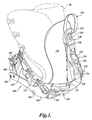
- FIGURE 1 is a three-quarter back perspective view of an embodiment of a snowboard binding, according to the teachings of the present invention;
- FIGURE 2A is a side view of the snowboard binding shown in FIGURE 1, with the highback in the full open position;
- FIGURE 2B is a side view of the snowboard binding shown in FIGURE 1, with the highback in a partially closed position;
- FIGURE 2C is a side view of the snowboard binding shown in FIGURE 1, with the highback in the locked position;
- FIGURE 3 is a perspective view of a second embodiment of a snowboard binding according to the teachings of the present invention;
- FIGURE 4A shows a side view of a second embodiment of a snowboard binding, according to the teachings of the present invention;
- FIGURE 4B is a side view of the snowboard binding shown in FIGURE 3A, with the highback in a partially closed position;
- FIGURE 4C is a side view of the snowboard binding shown in FIGURE 3A, with the highback in the locked position; and
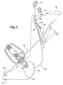
- FIGURE 5 is a partial side view of a third embodiment of a snowboard binding according to the teachings of the present invention.
- Refer now to the figures, wherein like numbers indicate like parts. A perspective view of a first preferred embodiment of a snowboard binding 100 according to the present invention is shown in FIGURES 1 and 2A-2C. The
binding 100 includes abase plate 102 that is adapted to be attached to the upper surface of a snowboard (not shown) in a conventional manner. Typically, the position and orientation of thebase plate 102 on the snowboard may be adjusted to suit the rider and the types of runs that the rider plans to make. A pair of oppositely disposed sidewall members 104 (one visible in FIGURES) is pivotally attached with apivot member 106 near a forward end of thebase plate 102. Atoe strap 108 and aninstep strap 110 are attached to thesidewall members 104, and includelatching mechanisms straps heel loop 112 is pivotably attached on both sides withpivot members 114 to thesidewall members 104. Theheel loop 112 is also pivotably attached on both sides to thebase plate 102 with pivot members 116 (FIGURE 2A, one shown). In this embodiment, thebinding 100 also includes a pair of oppositely disposedcable guides 118 that is fixedly attached to theheel loop 112. - A
pivoting highback 120, contoured to approximately conform to the back of the rider'sboot 90, extends upwardly from a pair of oppositely disposed pivotal attachment members 122 (FIGURE 2A, one shown) connecting thehighback 120 to theheel loop 112. A blockingmember 124 is adjustably attached to the back of thehighback 120. The blockingmember 124 has alower end 123 that is positioned to abut anupper edge 113 of theheel loop 112, limiting the backward rotation of thehighback 120 relative to theheel loop 112. The maximum angle between thehighback 120 and the base plate 102 (the maximum forward lean) may be selectively established from a range of maximum angles by slidably adjusting the position of the blockingmember 124 on thehighback 120. - A locking
lever 130 is pivotably attached to the blockingmember 124 near itsupper end 125. The lockinglever 130 is movable between an open position rotated away from the highback 120 (shown in FIGURE 2A) and a locked position rotated to be generally adjacent the back surface of the highback 120 (shown in FIGURE 2C). Acable 126 extends from a fixedattachment 128 to onesidewall member 104, rearwardly and around thehighback 120 slidably engaging one of thecable guide members 118 on theheel loop 112 through aslot 136 in thelever 130, then slidably engages the othercable guide member 118 and attaches to the other sidewall member 104 (not shown). - The locking
lever 130 further comprises a mechanism to facilitate engagement and disengagement of the lockinglever 130. For example, as seen most clearly in FIGURES 2A, 2B, and 2C, aflexible strap 140 is provided having afirst end portion 142 that is attached near aproximal end 134 of thelever 130, and asecond end portion 144 that engages thelever 130 at an intermediate location and extends over thedistal end 132 of thelever 130. In the current embodiment thefirst end portion 142 of theflexible strap 140 is fixed to the binding 100 between the blockingmember 124 and thehighback 120. Thesecond end portion 144 of theflexible strap 140 is removably attached to the lockinglever 130 with apost 138 that extends through a loop formed in thesecond end portion 144 of theflexible strap 140 and through theslot 136 in thelever 130. Other conventional attachment means can obviously be utilized without departing from the present invention. - The general operation of the binding 100 can now be understood, with particular reference to FIGURES 2A, 2B, and 2C, which show side views of the binding 100, in an open position (FIGURE 2A), partially closed position (FIGURE 2B), and a locked position (FIGURE 2C). In the open position, the
lever 130distal end 132 is disposed away from thehighback 120 and thehighback 120 is pivoted outwardly to facilitate entry of theboot 90 into the binding 100. In the binding 100, as thehighback 120 pivots outwardly theheel loop 112 pivots (clockwise in FIGURE 2A) about thepivot member 116, which causes thesidewall members 104 to pivot (counterclockwise in FIGURE 2) aboutpivot member 106, moving thestraps base plate 102 to further facilitate theboot 90 entry into the binding 100. - After inserting a
boot 90, the rider pulls upwardly on thestrap 140, as indicated by thearrow 80 in FIGURE 2B, to pivot thehighback 120 generally towards theboot 90. The movement of theheel loop 112 causes thesidewall members 104 to pivot downwardly, such that thestraps boot 90. The lockinglever 130 may now be placed in the locked position shown in FIGURE 2C by continuing to pull thestrap 140 upwardly and forwardly, causing thedistal end 132 of thelever 130 to pivot towards thehighback 120. It will be appreciated thatlever 130 pulls thecable 126 upwardly, producing an upward force on the cable guides 118, thereby pivoting the heel loop 112 (counterclockwise in FIGURE 2C) to the desired position. Typically, thestrap latching mechanisms straps boot 90 by engagement of thelever 130. Alternatively, the rider may elect to adjust the latchingmechanisms lever 130 to the locked position. - As discussed above, due to the position of the locking
lever 130 on the back of thehighback 120 and the typical need to engage the lockinglever 130 while on the slope and usually while wearing gloves, in prior art bindings it can be difficult to reach thedistal end 132 of the lockinglever 130 to move the lockinglever 130 to the locked position. Theflexible strap 140 provides a large, easily-engaged loop through which a rider can readily extend one or more fingers of a gloved hand. The rider then simply pulls inwardly and upwardly on theflexible strap 140 to pivot thelever 130 from the open position shown in FIGURE 2A to the locked position shown in FIGURE 2C. Also, the rider does not need to try to grasp thelever 130 or to extend a gloved finger behind thedistal end 132 of thelever 130 for disengagement. Rather, the rider can easily disengage the lockinglever 130 using the large loop formed by thestrap 140 and pulling rearwardly. For example, the loop may be grabbed as a whole to pull rearwardly to disengage the lever, or the rider can insert a finger in the loop and pull rearwardly. In particular, the rider does not have to get a gloved hand behind thelever 130 that is held in tension against thehighback 120 in order to disengage thelever 130. Thestrap 140 also makes it easier to move thelever 130 to the locked position, because the rider does not need to get under the end of thelever 130, which is very close to the ground (e.g., the surface of the snowboard) in the open position. - The
flexible strap 140 is lightweight and easily installed. In particular, it will be appreciated that theflexible strap 140 permits the use of asmaller locking lever 130 because the locking lever does not have to be engaged directly by the gloved hands of the rider. The flexible strap may be made from any suitably strong material that is able to withstand the low temperature and icy conditions encountered in snowboarding. In a current embodiment, theflexible strap 140 is made from a rugged polymeric material, such as nylon. - Referring now to FIGURES 3 and 4A-4C, a second embodiment of the present invention is shown. FIGURE 3 shows a perspective view of a binding 200, similar to the binding shown in FIGURE 1. Except for the lever engagement mechanism, the second embodiment of the binding 200 is identical to the binding 100 described above. In general, aspects of the binding 200 of this second embodiment are the same as the binding 100 shown in FIGURE 1 and will not be repeated here for brevity and clarity.
- In this second embodiment, a semirigid,
flexible panel 202 is attached to the back of thehighback 120. The proximal end of thepanel 202 is fixed between the blockingmember 124 and thehighback 120 and extends upwardly from the blockingmember 124. Aguide element 204 defining an aperture therethrough is attached to the distal end of theflexible panel 202. Oneend portion 205 of aflexible cord 206 is attached to the lockinglever 130 at an intermediate position on the lockinglever 130. Thecord 206 extends upwardly through the aperture in theguide element 204. A relatively large,graspable element 210 is attached at asecond end portion 207 of thecord 206. In the current embodiment, thegraspable element 210 is a sewn leather loop, although other suitable materials may be used--including, for example, a polymeric material, a sturdy fabric element, and the like. Thecord 206 may be formed from a natural fiber or synthetic material, for example, or metal cable or the like. - Refer now in particular to the side views of the binding 200 shown in FIGURES 4A-4C, these figures sequential showing stages in the engagement of the binding 200. To mount the snowboard, the rider typically first opens the binding 200 by rotating the
highback 120 rearwardly, generally to the position shown in FIGURE 4A. Rotating thehighback 120 causes thesidewalls 104 to pivot about thepivot member 106, such that thestraps base plate 102, as discussed above. The rider then inserts aboot 90 onto thebase plate 102, sliding theboot 90 generally to a forward position, and pulls upwardly and inwardly on thegraspable element 210, as indicated by thearrow 82 in FIGURE 4B. Thecord 206 pulls thelever 130 upwardly, pivoting thehighback 120 toward the maximum forward lean position. The rider pulls thegraspable element 210 until thelever 130 locks into the locked position shown in FIGURE 4C. As previously discussed, thesidewalls 104 move thestraps boot 90, to secure theboot 90 in place. - To disengage the binding 200, the rider pulls generally rearwardly on the
graspable element 210, causing thepanel 202 to exert a rearward force on the distal end of thelever 130, pivoting thelever 130 toward the open position. The rider then pivots thehighback 120 rearwardly to remove theboot 90. - It will now be appreciated that the
flexible panel 202 provides two functions. First, it aids in the release of thelever 130 when thelever 130 is in the locked position and under tension by pushing against the end of thelever 130 when the rider pulls rearwardly on thegraspable element 210. Also, it aids in moving thelever 130 into the locked position by effectively extending the point of where the lever is held, increasing the leverage gain. Although theflexible panel 202 in the disclosed embodiment is fixed between the blockingmember 124 and thehighback 120, other similar constructions are possible without departing from the present invention. For example theflexible panel 202 may be integrally formed with the blocking member, attached directly to the highback, or removably attached to the binding 200. - A third embodiment of the present invention is shown in FIGURE 5, which shows a side view of the rearward portion of a binding 300 having a
base plate 302 with a pair of oppositely-disposed, fixed sidewalls 304 (one shown) that may be formed as integral parts of thebase plate 302 or fixedly attached to thebase plate 302. In this embodiment of the binding 300, thesidewalls 304 are not pivotable and thehighback 320 is pivotably attached directly to thesidewalls 304 by apivot member 305. A separable heel loop is not required. Acable 326 extends from a fixed attachment at anintermediate position 303 on one of thesidewalls 304, rearwardly and behind thehighback 320 to slidably engage a lockinglever 330, and around to thesidewall 304 on the opposite side (not visible). The lockinglever 330 is movable between a locked position, shown in FIGURE 5, and an open position, shown in phantom. Typically, thecable 326 effective length is adjustable--for example, with a threadable attachment at 303 (not shown)--and provides a mechanism for controlling the maximum forward lean of thehighback 320. When the lockinglever 330 is in the open position, thehighback 320 can pivot about thepivot member 305 away from the base plate 302 (clockwise in FIGURE 5), allowing the rider to insert a boot under theinstep strap 110 and into the binding 300. - The mechanism to facilitate engaging (locking) and disengaging the
lever 330 is essentially the same as that shown in FIGURE 3. In particular, aflexible panel 202 extends upwardly, generally from the base of thelever 330. Acord guide 204 is disposed at the distal end of thepanel 202. Acord 206 is attached near the end of thelever 330 and extends upwardly through theguide 204. Agraspable element 210 is attached to the opposite end of thecord 206. The rider can therefore pull upwardly and forwardly, as indicated by thearrow 84 in FIGURE 5, to move thelever 330 into the locked position. When disengaging from the binding 300, the rider can pull basically rearwardly on thegraspable element 210 to pivot thelever 330 to the open position, and then pivot thehighback 320 rearwardly. - It will be apparent from the present disclosure that the binding 300 may alternatively utilize the
flexible strap 140 shown in FIGURES 1 and 2A-2C and attached to thehighback 320 andlever 330 rather than thecord 206 to facilitate engagement and disengagement of the lockinglever 330. - While the preferred embodiment of the invention has been illustrated and described, it will be appreciated that various changes can be made therein without departing from the spirit and scope of the invention.
- The embodiments of the invention in which an exclusive property or privilege is claimed are defined as follows:
Claims (19)
- A binding comprising:a base plate adapted to be attached to a snowboard;a highback pivotably attached to the base plate;a locking lever having a proximal end pivotably attached to a back side of the highback and a distal end, the locking lever being pivotable between an open positionwherein the distal end is disposed away from the highback and a locked position wherein the distal end is disposed near the highback; and
a flexible member having a first portion attached to the highback near the proximal end of the locking lever and a second portion attached to the locking lever at a position away from the proximal end of the locking lever;
wherein the locking lever is movable from the open position to the locked position by pulling upwardly on the flexible member. - The binding of Claim 1, wherein the flexible member comprises an elongate strap.
- The binding of Claim 2, wherein the elongate strap is formed from a polymeric material.
- The binding of Claim 2, further comprises a U-shaped heel loop that is pivotably attached to the base plate and wherein the highback is pivotably attached to the base plate with the heel loop.
- The binding of Claim 4, wherein the base plate comprises a base portion and a pair of oppositely-disposed sidewalls are pivotably attached to the base portion, the sidewalls supporting an adjustable instep strap therebetween, and wherein the sidewalls are also pivotably attached to the heel loop such that pivoting the heel loop on the base plate will cause the sidewalls to pivot.
- The binding of Claim 5, wherein the binding further comprises a cable having a first end that is attached to one sidewall, a second end that attaches to the other sidewall, and wherein the cable extends around the highback and engages the locking lever.
- The binding of Claim 6, further comprising at least one cable guide fixedly attached to the heel loop, wherein the cable engages the cable guide.
- The binding of Claim 7, wherein when the locking lever is in the locked position, the cable is in tension and arranged such that the cable exerts an upward force on the heel loop cable guide.
- The binding of Claim 7, further comprising a blocking member that is adjustably attached to the highback such that a lower end of the blocking member abuts an upper edge of the heel loop.
- The binding of Claim 1, wherein the flexible member comprises a semirigid panel that extends upwardly from the proximal end of the locking lever, the semirigid panel having a cord guide with an aperture, and a cord having a first end that is attached to the locking lever, the cord extending through the aperture in the cord guide.
- The binding of Claim 10, wherein the flexible member further comprises a graspable member that is attached to a second end of the cord.
- The binding of Claim 11, wherein the graspable member is a leather loop.
- The binding of Claim 11, further comprises a U-shaped heel loop that is pivotably attached to the base plate, and wherein the highback is pivotably attached to the base plate with the heel loop.
- The binding of Claim 13, wherein the base plate comprises a base portion and a pair of oppositely-disposed sidewalls pivotably attached to the base portion, the sidewalls supporting an adjustable instep strap therebetween, and wherein the sidewalls are also pivotably attached to the heel loop such that pivoting the heel loop on the base plate will cause the sidewalls to pivot.
- The binding of Claim 14, wherein the binding further comprises a cable having a first end that is attached to one sidewall, a second end that attaches to the other sidewall, and wherein the cable extends around the highback and engages the locking lever.
- The binding of Claim 15, further comprising at least one cable guide fixedly attached to the heel loop, wherein the cable engages the cable guide.
- The binding of Claim 16, wherein when the locking lever is in the locked position the cable is in tension and arranged such that the cable exerts an upward force on the heel loop cable guide.
- The binding of Claim 16, further comprising a blocking member that is adjustably attached to the highback such that a lower end of the blocking member abuts an upper edge of the heel loop.
- A snowboard binding comprising:a base plate having a base portion adapted to be attached to a snowboard and oppositely-disposed sidewalls;a highback pivotably attached to the oppositely-disposed sidewalls;a locking lever pivotably attached to the highback, the locking lever being movable between an open position and a locked position;a cable having first and second ends attached to the base plate, the cable extending through a slot in the locking lever;a semirigid panel attached to the highback, the semirigid panel having a cord guide attached thereto; anda cord having a first end attached to the locking lever and a second end having a graspable member, the cord extending through the cable guide;wherein the lever can be moved from the open position to the locked position by pulling upwardly on the graspable member.
Applications Claiming Priority (1)
| Application Number | Priority Date | Filing Date | Title |
|---|---|---|---|
| US11/117,059 US7246811B2 (en) | 2005-04-27 | 2005-04-27 | Snowboard binding engagement mechanism |
Publications (3)
| Publication Number | Publication Date |
|---|---|
| EP1716892A2 true EP1716892A2 (en) | 2006-11-02 |
| EP1716892A3 EP1716892A3 (en) | 2007-12-05 |
| EP1716892B1 EP1716892B1 (en) | 2009-08-26 |
Family
ID=36809582
Family Applications (1)
| Application Number | Title | Priority Date | Filing Date |
|---|---|---|---|
| EP06005913A Expired - Lifetime EP1716892B1 (en) | 2005-04-27 | 2006-03-22 | Snowboard binding engagement mechanism |
Country Status (6)
| Country | Link |
|---|---|
| US (1) | US7246811B2 (en) |
| EP (1) | EP1716892B1 (en) |
| JP (1) | JP2006305329A (en) |
| AT (1) | ATE440649T1 (en) |
| CA (1) | CA2544979A1 (en) |
| DE (1) | DE602006008687D1 (en) |
Cited By (1)
| Publication number | Priority date | Publication date | Assignee | Title |
|---|---|---|---|---|
| EP2380639A4 (en) * | 2008-12-23 | 2013-10-30 | Buzrun Co Ltd | Snowboard binding |
Families Citing this family (43)
| Publication number | Priority date | Publication date | Assignee | Title |
|---|---|---|---|---|
| DE10305764B4 (en) * | 2003-02-11 | 2007-04-12 | Goodwell International Ltd., Tortola | snowboard binding |
| WO2006074295A1 (en) * | 2005-01-07 | 2006-07-13 | Rome Snowboards Corporation | Snowboard binding release mechanism |
| US8192244B2 (en) * | 2005-08-16 | 2012-06-05 | Connelly Skis, Inc. | Water sports binding assembly |
| US7134928B1 (en) * | 2005-08-16 | 2006-11-14 | Connelly Skis, Inc. | Binding for water sports boards |
| US7516976B2 (en) * | 2005-08-29 | 2009-04-14 | The Burton Corporation | Strap for snowboard boots or bindings |
| US7669880B2 (en) * | 2005-08-29 | 2010-03-02 | The Burton Corporation | Strap for snowboard boots or bindings |
| US7306241B2 (en) * | 2005-08-29 | 2007-12-11 | The Burton Corporation | Strap for snowboard boots or bindings |
| US8016315B2 (en) | 2005-09-30 | 2011-09-13 | Flow Sports, Inc. | Modular binding for sports board |
| KR20080108404A (en) * | 2005-11-30 | 2008-12-15 | 이 아이 듀폰 디 네모아 앤드 캄파니 | Binding with adjustable heel-cup frame |
| US20070182130A1 (en) * | 2006-02-06 | 2007-08-09 | Laser Brian K | Snowboard binding |
| US7887082B2 (en) | 2006-09-01 | 2011-02-15 | Wire Core Strap, Inc. | Reformable closure device strap |
| US7621542B2 (en) * | 2006-11-20 | 2009-11-24 | The Burton Corporation | Snowboard binding and related methods |
| US20080258434A1 (en) * | 2007-04-13 | 2008-10-23 | Krenn Thomas | Snowboard binding with rear step-in and securing of boot by toe element |
| WO2009059227A1 (en) * | 2007-11-02 | 2009-05-07 | Stout Medical Group, L.P. | Expandable attachment device and method |
| US20100095494A1 (en) * | 2008-10-16 | 2010-04-22 | Daniel Joshua Martin | Bicycle Shoe Strap Assembly |
| US8469372B2 (en) | 2008-10-23 | 2013-06-25 | Bryce M. Kloster | Splitboard binding apparatus |
| EP2414057B1 (en) * | 2009-04-03 | 2016-06-29 | Sam Sport And Marketing AG | Snowboard binding with asymetric highback |
| USD630419S1 (en) | 2009-06-05 | 2011-01-11 | Dashamerica, Inc. | Base plate for adjustable strap |
| USD611237S1 (en) | 2009-06-05 | 2010-03-09 | Dashamerica, Inc. | Cycling shoe insole |
| USD636983S1 (en) | 2009-06-05 | 2011-05-03 | Dashamerica, Inc. | Cycling shoe |
| US8191917B2 (en) * | 2009-09-09 | 2012-06-05 | Charlton Co., Ltd. | Snowboard binding |
| KR101237403B1 (en) * | 2011-04-22 | 2013-02-27 | 정성록 | snowboard binding |
| US8857845B2 (en) | 2012-01-30 | 2014-10-14 | Todd Ohlheiser | Snowboard binding locking lever pull cable |
| US9238168B2 (en) | 2012-02-10 | 2016-01-19 | Bryce M. Kloster | Splitboard joining device |
| US9266010B2 (en) | 2012-06-12 | 2016-02-23 | Tyler G. Kloster | Splitboard binding with adjustable leverage devices |
| EP2692397A1 (en) | 2012-08-01 | 2014-02-05 | Todd Ohlheiser | Snowboard binding locking lever pull cable |
| KR101438174B1 (en) | 2013-09-27 | 2014-09-11 | 주식회사 버즈런 | Binding for snowboard |
| US9713758B2 (en) * | 2013-10-16 | 2017-07-25 | Kevin John LEFSRUD | Ski boot frame |
| US9220970B1 (en) | 2014-11-14 | 2015-12-29 | The Burton Corporation | Snowboard binding and boot |
| US9149711B1 (en) | 2014-11-14 | 2015-10-06 | The Burton Corporation | Snowboard binding and boot |
| EP3218073B1 (en) | 2014-11-14 | 2021-05-19 | The Burton Corporation | Snowboard binding |
| US9545560B2 (en) * | 2014-12-22 | 2017-01-17 | Helos, Llc | Heel locking binding system |
| US9395154B1 (en) * | 2015-01-07 | 2016-07-19 | Barnett Outdoors, Llc | Weapon stabilizing device and method |
| US10029165B2 (en) | 2015-04-27 | 2018-07-24 | Bryce M. Kloster | Splitboard joining device |
| US9604122B2 (en) | 2015-04-27 | 2017-03-28 | Bryce M. Kloster | Splitboard joining device |
| JP6060465B1 (en) * | 2015-07-24 | 2017-01-18 | 株式会社 ネオスノーレンタル | Snowboard binding |
| KR101767736B1 (en) * | 2015-08-25 | 2017-08-14 | 박순익 | Binding For Snowboard |
| US10086257B2 (en) * | 2016-06-28 | 2018-10-02 | Mad Jack Snow Sports | Apparatus for adapting a snowboard boot for use with an alpine ski |
| KR101870936B1 (en) | 2017-02-16 | 2018-06-25 | 박순익 | Binding For Sports boots |
| US10105588B1 (en) * | 2017-09-26 | 2018-10-23 | Chasen Massey | Snowboard binding with adjustment memory |
| US11117042B2 (en) | 2019-05-03 | 2021-09-14 | Bryce M. Kloster | Splitboard binding |
| US11938394B2 (en) | 2021-02-22 | 2024-03-26 | Bryce M. Kloster | Splitboard joining device |
| US12611587B1 (en) * | 2025-05-13 | 2026-04-28 | Kenneth John Achenbach | Binding safety release device |
Citations (2)
| Publication number | Priority date | Publication date | Assignee | Title |
|---|---|---|---|---|
| DE29617998U1 (en) | 1996-10-16 | 1997-03-27 | Playmaker Co | Snowboard binding |
| US5727797A (en) | 1996-02-06 | 1998-03-17 | Preston Binding Company | Snowboard binding assembly with adjustable forward lean backplate |
Family Cites Families (22)
| Publication number | Priority date | Publication date | Assignee | Title |
|---|---|---|---|---|
| FR2547175B1 (en) * | 1983-06-08 | 1985-11-08 | Salomon & Fils F | IMPROVEMENT IN SKI BOOTS WITH REAR ENTRY |
| FR2577118B1 (en) * | 1985-02-08 | 1987-03-20 | Salomon Sa | BACK ENTRY TYPE SKI BOOT |
| FR2626189B1 (en) * | 1988-01-21 | 1990-03-09 | Lauzier Sa | ATTACHMENT FOR SKI, MONOSKI OR SNOW SURF |
| JPH0739406A (en) | 1993-07-30 | 1995-02-10 | Ykk Kk | Tie |
| US5556123A (en) * | 1994-05-12 | 1996-09-17 | Fournier; Louis | Snowboard binding with compensating plate |
| DE4435113C1 (en) | 1994-09-30 | 1996-05-30 | Goodwell Int Ltd | Snowboard binding |
| JPH09276473A (en) * | 1996-04-08 | 1997-10-28 | Tokyo Ichitsuru:Kk | Binding for snowboard |
| IT1283817B1 (en) * | 1996-08-21 | 1998-04-30 | Pida S R L | SNOW TABLE ATTACK |
| US6027136A (en) * | 1997-01-08 | 2000-02-22 | The Burton Corporation | System for preventing toe-edge travel of a hi-back |
| US6648365B1 (en) | 1997-01-08 | 2003-11-18 | The Burton Corporation | Snowboard binding |
| US6382641B2 (en) | 1998-05-19 | 2002-05-07 | K-2 Corporation | Snowboard binding system with automatic forward lean support |
| US6406040B1 (en) | 1998-10-21 | 2002-06-18 | Nike, Inc. | Highback snowboard binding |
| FR2801514B1 (en) | 1999-11-25 | 2001-12-21 | Rossignol Sa | SURF FIXING |
| US6543793B1 (en) * | 2000-10-03 | 2003-04-08 | The Burton Corporation | Highback formed of multiple materials |
| FR2804877B1 (en) | 2000-02-15 | 2002-05-24 | Rossignol Sa | SURF FIXING |
| US6554296B1 (en) * | 2000-04-28 | 2003-04-29 | The Burton Corporation | Highback with independent forward lean adjustment |
| US6467795B1 (en) | 2000-12-29 | 2002-10-22 | Shimano Inc. | Snowboard binding with highback |
| DE50101185D1 (en) | 2001-01-31 | 2004-01-29 | Tyrolia Freizeitgeraete | Snowboard binding |
| US6742800B2 (en) | 2001-04-18 | 2004-06-01 | Shimano, Inc. | Snowboard binding system |
| DE10252635B4 (en) | 2002-11-11 | 2004-11-18 | Goodwell International Ltd., Tortola | snowboard binding |
| DE10305764B4 (en) * | 2003-02-11 | 2007-04-12 | Goodwell International Ltd., Tortola | snowboard binding |
| ATE330678T1 (en) * | 2003-02-20 | 2006-07-15 | Jean-Pierre Edmond | BINDING FOR ATTACHING A SHOE TO A SNOW BOARD |
-
2005
- 2005-04-27 US US11/117,059 patent/US7246811B2/en not_active Expired - Fee Related
-
2006
- 2006-03-22 AT AT06005913T patent/ATE440649T1/en not_active IP Right Cessation
- 2006-03-22 DE DE602006008687T patent/DE602006008687D1/en not_active Expired - Lifetime
- 2006-03-22 EP EP06005913A patent/EP1716892B1/en not_active Expired - Lifetime
- 2006-03-24 JP JP2006082987A patent/JP2006305329A/en active Pending
- 2006-04-27 CA CA002544979A patent/CA2544979A1/en not_active Abandoned
Patent Citations (2)
| Publication number | Priority date | Publication date | Assignee | Title |
|---|---|---|---|---|
| US5727797A (en) | 1996-02-06 | 1998-03-17 | Preston Binding Company | Snowboard binding assembly with adjustable forward lean backplate |
| DE29617998U1 (en) | 1996-10-16 | 1997-03-27 | Playmaker Co | Snowboard binding |
Cited By (1)
| Publication number | Priority date | Publication date | Assignee | Title |
|---|---|---|---|---|
| EP2380639A4 (en) * | 2008-12-23 | 2013-10-30 | Buzrun Co Ltd | Snowboard binding |
Also Published As
| Publication number | Publication date |
|---|---|
| US7246811B2 (en) | 2007-07-24 |
| US20060244241A1 (en) | 2006-11-02 |
| EP1716892B1 (en) | 2009-08-26 |
| CA2544979A1 (en) | 2006-10-27 |
| ATE440649T1 (en) | 2009-09-15 |
| DE602006008687D1 (en) | 2009-10-08 |
| JP2006305329A (en) | 2006-11-09 |
| EP1716892A3 (en) | 2007-12-05 |
Similar Documents
| Publication | Publication Date | Title |
|---|---|---|
| EP1716892B1 (en) | Snowboard binding engagement mechanism | |
| US7210252B2 (en) | Step-in snowboard binding and boot therefor | |
| US6679515B2 (en) | Hinge strap for snowboard conventional binding | |
| US5609347A (en) | Snowboard bindings with release apparatus | |
| US6554295B2 (en) | Strapless toelock binding for snowboards | |
| US5857700A (en) | Quick-release snowboard binding | |
| EP1033085B1 (en) | Active highback system for a snowboard boot | |
| US7047673B2 (en) | Step-in snowshoe binding system | |
| AU2006279503B2 (en) | Binding for water sports boards | |
| CA2803441A1 (en) | Snowboard binding locking lever pull cable | |
| EP2949368A1 (en) | Step-in / step-out snowboard binding system | |
| US8192244B2 (en) | Water sports binding assembly | |
| JP2004523293A (en) | Universal fastener device | |
| US11731029B2 (en) | Set of coupling assemblies for a board for board sports | |
| EP2692397A1 (en) | Snowboard binding locking lever pull cable | |
| HK1036740B (en) | Dual-action buckle | |
| HK1036740A1 (en) | Dual-action buckle |
Legal Events
| Date | Code | Title | Description |
|---|---|---|---|
| PUAI | Public reference made under article 153(3) epc to a published international application that has entered the european phase |
Free format text: ORIGINAL CODE: 0009012 |
|
| 17P | Request for examination filed |
Effective date: 20060322 |
|
| AK | Designated contracting states |
Kind code of ref document: A2 Designated state(s): AT BE BG CH CY CZ DE DK EE ES FI FR GB GR HU IE IS IT LI LT LU LV MC NL PL PT RO SE SI SK TR |
|
| AX | Request for extension of the european patent |
Extension state: AL BA HR MK YU |
|
| RAP1 | Party data changed (applicant data changed or rights of an application transferred) |
Owner name: K-2 CORPORATION |
|
| PUAL | Search report despatched |
Free format text: ORIGINAL CODE: 0009013 |
|
| AK | Designated contracting states |
Kind code of ref document: A3 Designated state(s): AT BE BG CH CY CZ DE DK EE ES FI FR GB GR HU IE IS IT LI LT LU LV MC NL PL PT RO SE SI SK TR |
|
| AX | Request for extension of the european patent |
Extension state: AL BA HR MK YU |
|
| 17Q | First examination report despatched |
Effective date: 20080328 |
|
| AKX | Designation fees paid |
Designated state(s): AT BE BG CH CY CZ DE DK EE ES FI FR GB GR HU IE IS IT LI LT LU LV MC NL PL PT RO SE SI SK TR |
|
| GRAP | Despatch of communication of intention to grant a patent |
Free format text: ORIGINAL CODE: EPIDOSNIGR1 |
|
| GRAS | Grant fee paid |
Free format text: ORIGINAL CODE: EPIDOSNIGR3 |
|
| GRAA | (expected) grant |
Free format text: ORIGINAL CODE: 0009210 |
|
| AK | Designated contracting states |
Kind code of ref document: B1 Designated state(s): AT BE BG CH CY CZ DE DK EE ES FI FR GB GR HU IE IS IT LI LT LU LV MC NL PL PT RO SE SI SK TR |
|
| REG | Reference to a national code |
Ref country code: GB Ref legal event code: FG4D |
|
| REG | Reference to a national code |
Ref country code: CH Ref legal event code: EP |
|
| REG | Reference to a national code |
Ref country code: IE Ref legal event code: FG4D |
|
| REF | Corresponds to: |
Ref document number: 602006008687 Country of ref document: DE Date of ref document: 20091008 Kind code of ref document: P |
|
| LTIE | Lt: invalidation of european patent or patent extension |
Effective date: 20090826 |
|
| PG25 | Lapsed in a contracting state [announced via postgrant information from national office to epo] |
Ref country code: LT Free format text: LAPSE BECAUSE OF FAILURE TO SUBMIT A TRANSLATION OF THE DESCRIPTION OR TO PAY THE FEE WITHIN THE PRESCRIBED TIME-LIMIT Effective date: 20090826 Ref country code: IS Free format text: LAPSE BECAUSE OF FAILURE TO SUBMIT A TRANSLATION OF THE DESCRIPTION OR TO PAY THE FEE WITHIN THE PRESCRIBED TIME-LIMIT Effective date: 20091226 Ref country code: FI Free format text: LAPSE BECAUSE OF FAILURE TO SUBMIT A TRANSLATION OF THE DESCRIPTION OR TO PAY THE FEE WITHIN THE PRESCRIBED TIME-LIMIT Effective date: 20090826 Ref country code: SE Free format text: LAPSE BECAUSE OF FAILURE TO SUBMIT A TRANSLATION OF THE DESCRIPTION OR TO PAY THE FEE WITHIN THE PRESCRIBED TIME-LIMIT Effective date: 20090826 Ref country code: AT Free format text: LAPSE BECAUSE OF FAILURE TO SUBMIT A TRANSLATION OF THE DESCRIPTION OR TO PAY THE FEE WITHIN THE PRESCRIBED TIME-LIMIT Effective date: 20090826 |
|
| NLV1 | Nl: lapsed or annulled due to failure to fulfill the requirements of art. 29p and 29m of the patents act | ||
| PG25 | Lapsed in a contracting state [announced via postgrant information from national office to epo] |
Ref country code: NL Free format text: LAPSE BECAUSE OF FAILURE TO SUBMIT A TRANSLATION OF THE DESCRIPTION OR TO PAY THE FEE WITHIN THE PRESCRIBED TIME-LIMIT Effective date: 20090826 Ref country code: LV Free format text: LAPSE BECAUSE OF FAILURE TO SUBMIT A TRANSLATION OF THE DESCRIPTION OR TO PAY THE FEE WITHIN THE PRESCRIBED TIME-LIMIT Effective date: 20090826 Ref country code: SI Free format text: LAPSE BECAUSE OF FAILURE TO SUBMIT A TRANSLATION OF THE DESCRIPTION OR TO PAY THE FEE WITHIN THE PRESCRIBED TIME-LIMIT Effective date: 20090826 Ref country code: PL Free format text: LAPSE BECAUSE OF FAILURE TO SUBMIT A TRANSLATION OF THE DESCRIPTION OR TO PAY THE FEE WITHIN THE PRESCRIBED TIME-LIMIT Effective date: 20090826 |
|
| PG25 | Lapsed in a contracting state [announced via postgrant information from national office to epo] |
Ref country code: PT Free format text: LAPSE BECAUSE OF FAILURE TO SUBMIT A TRANSLATION OF THE DESCRIPTION OR TO PAY THE FEE WITHIN THE PRESCRIBED TIME-LIMIT Effective date: 20091228 Ref country code: BG Free format text: LAPSE BECAUSE OF FAILURE TO SUBMIT A TRANSLATION OF THE DESCRIPTION OR TO PAY THE FEE WITHIN THE PRESCRIBED TIME-LIMIT Effective date: 20091126 Ref country code: CY Free format text: LAPSE BECAUSE OF FAILURE TO SUBMIT A TRANSLATION OF THE DESCRIPTION OR TO PAY THE FEE WITHIN THE PRESCRIBED TIME-LIMIT Effective date: 20090826 |
|
| PG25 | Lapsed in a contracting state [announced via postgrant information from national office to epo] |
Ref country code: EE Free format text: LAPSE BECAUSE OF FAILURE TO SUBMIT A TRANSLATION OF THE DESCRIPTION OR TO PAY THE FEE WITHIN THE PRESCRIBED TIME-LIMIT Effective date: 20090826 Ref country code: RO Free format text: LAPSE BECAUSE OF FAILURE TO SUBMIT A TRANSLATION OF THE DESCRIPTION OR TO PAY THE FEE WITHIN THE PRESCRIBED TIME-LIMIT Effective date: 20090826 Ref country code: ES Free format text: LAPSE BECAUSE OF FAILURE TO SUBMIT A TRANSLATION OF THE DESCRIPTION OR TO PAY THE FEE WITHIN THE PRESCRIBED TIME-LIMIT Effective date: 20091207 Ref country code: DK Free format text: LAPSE BECAUSE OF FAILURE TO SUBMIT A TRANSLATION OF THE DESCRIPTION OR TO PAY THE FEE WITHIN THE PRESCRIBED TIME-LIMIT Effective date: 20090826 Ref country code: CZ Free format text: LAPSE BECAUSE OF FAILURE TO SUBMIT A TRANSLATION OF THE DESCRIPTION OR TO PAY THE FEE WITHIN THE PRESCRIBED TIME-LIMIT Effective date: 20090826 |
|
| PG25 | Lapsed in a contracting state [announced via postgrant information from national office to epo] |
Ref country code: SK Free format text: LAPSE BECAUSE OF FAILURE TO SUBMIT A TRANSLATION OF THE DESCRIPTION OR TO PAY THE FEE WITHIN THE PRESCRIBED TIME-LIMIT Effective date: 20090826 |
|
| PG25 | Lapsed in a contracting state [announced via postgrant information from national office to epo] |
Ref country code: BE Free format text: LAPSE BECAUSE OF FAILURE TO SUBMIT A TRANSLATION OF THE DESCRIPTION OR TO PAY THE FEE WITHIN THE PRESCRIBED TIME-LIMIT Effective date: 20090826 |
|
| PLBE | No opposition filed within time limit |
Free format text: ORIGINAL CODE: 0009261 |
|
| STAA | Information on the status of an ep patent application or granted ep patent |
Free format text: STATUS: NO OPPOSITION FILED WITHIN TIME LIMIT |
|
| 26N | No opposition filed |
Effective date: 20100527 |
|
| PG25 | Lapsed in a contracting state [announced via postgrant information from national office to epo] |
Ref country code: GR Free format text: LAPSE BECAUSE OF FAILURE TO SUBMIT A TRANSLATION OF THE DESCRIPTION OR TO PAY THE FEE WITHIN THE PRESCRIBED TIME-LIMIT Effective date: 20091127 Ref country code: MC Free format text: LAPSE BECAUSE OF NON-PAYMENT OF DUE FEES Effective date: 20100331 |
|
| REG | Reference to a national code |
Ref country code: CH Ref legal event code: PL |
|
| GBPC | Gb: european patent ceased through non-payment of renewal fee |
Effective date: 20100322 |
|
| REG | Reference to a national code |
Ref country code: FR Ref legal event code: ST Effective date: 20101130 |
|
| PG25 | Lapsed in a contracting state [announced via postgrant information from national office to epo] |
Ref country code: FR Free format text: LAPSE BECAUSE OF NON-PAYMENT OF DUE FEES Effective date: 20100331 Ref country code: IE Free format text: LAPSE BECAUSE OF NON-PAYMENT OF DUE FEES Effective date: 20100322 |
|
| PG25 | Lapsed in a contracting state [announced via postgrant information from national office to epo] |
Ref country code: CH Free format text: LAPSE BECAUSE OF NON-PAYMENT OF DUE FEES Effective date: 20100331 Ref country code: LI Free format text: LAPSE BECAUSE OF NON-PAYMENT OF DUE FEES Effective date: 20100331 |
|
| PG25 | Lapsed in a contracting state [announced via postgrant information from national office to epo] |
Ref country code: IT Free format text: LAPSE BECAUSE OF FAILURE TO SUBMIT A TRANSLATION OF THE DESCRIPTION OR TO PAY THE FEE WITHIN THE PRESCRIBED TIME-LIMIT Effective date: 20090826 Ref country code: GB Free format text: LAPSE BECAUSE OF NON-PAYMENT OF DUE FEES Effective date: 20100322 |
|
| PG25 | Lapsed in a contracting state [announced via postgrant information from national office to epo] |
Ref country code: HU Free format text: LAPSE BECAUSE OF FAILURE TO SUBMIT A TRANSLATION OF THE DESCRIPTION OR TO PAY THE FEE WITHIN THE PRESCRIBED TIME-LIMIT Effective date: 20100227 Ref country code: LU Free format text: LAPSE BECAUSE OF NON-PAYMENT OF DUE FEES Effective date: 20100322 |
|
| PG25 | Lapsed in a contracting state [announced via postgrant information from national office to epo] |
Ref country code: TR Free format text: LAPSE BECAUSE OF FAILURE TO SUBMIT A TRANSLATION OF THE DESCRIPTION OR TO PAY THE FEE WITHIN THE PRESCRIBED TIME-LIMIT Effective date: 20090826 |
|
| PGFP | Annual fee paid to national office [announced via postgrant information from national office to epo] |
Ref country code: DE Payment date: 20170329 Year of fee payment: 12 |
|
| REG | Reference to a national code |
Ref country code: DE Ref legal event code: R119 Ref document number: 602006008687 Country of ref document: DE |
|
| PG25 | Lapsed in a contracting state [announced via postgrant information from national office to epo] |
Ref country code: DE Free format text: LAPSE BECAUSE OF NON-PAYMENT OF DUE FEES Effective date: 20181002 |