EP1716737A1 - A four wheel drive harvester with slip control. - Google Patents
A four wheel drive harvester with slip control. Download PDFInfo
- Publication number
- EP1716737A1 EP1716737A1 EP06113318A EP06113318A EP1716737A1 EP 1716737 A1 EP1716737 A1 EP 1716737A1 EP 06113318 A EP06113318 A EP 06113318A EP 06113318 A EP06113318 A EP 06113318A EP 1716737 A1 EP1716737 A1 EP 1716737A1
- Authority
- EP
- European Patent Office
- Prior art keywords
- speed
- pump
- ground
- displacement
- motor
- Prior art date
- Legal status (The legal status is an assumption and is not a legal conclusion. Google has not performed a legal analysis and makes no representation as to the accuracy of the status listed.)
- Granted
Links
Images


Classifications
-
- F—MECHANICAL ENGINEERING; LIGHTING; HEATING; WEAPONS; BLASTING
- F16—ENGINEERING ELEMENTS AND UNITS; GENERAL MEASURES FOR PRODUCING AND MAINTAINING EFFECTIVE FUNCTIONING OF MACHINES OR INSTALLATIONS; THERMAL INSULATION IN GENERAL
- F16H—GEARING
- F16H61/00—Control functions within control units of change-speed- or reversing-gearings for conveying rotary motion ; Control of exclusively fluid gearing, friction gearing, gearings with endless flexible members or other particular types of gearing
- F16H61/38—Control of exclusively fluid gearing
- F16H61/40—Control of exclusively fluid gearing hydrostatic
- F16H61/42—Control of exclusively fluid gearing hydrostatic involving adjustment of a pump or motor with adjustable output or capacity
- F16H61/421—Motor capacity control by electro-hydraulic control means, e.g. using solenoid valves
-
- A—HUMAN NECESSITIES
- A01—AGRICULTURE; FORESTRY; ANIMAL HUSBANDRY; HUNTING; TRAPPING; FISHING
- A01D—HARVESTING; MOWING
- A01D41/00—Combines, i.e. harvesters or mowers combined with threshing devices
- A01D41/12—Details of combines
- A01D41/127—Control or measuring arrangements specially adapted for combines
- A01D41/1274—Control or measuring arrangements specially adapted for combines for drives
-
- B—PERFORMING OPERATIONS; TRANSPORTING
- B60—VEHICLES IN GENERAL
- B60K—ARRANGEMENT OR MOUNTING OF PROPULSION UNITS OR OF TRANSMISSIONS IN VEHICLES; ARRANGEMENT OR MOUNTING OF PLURAL DIVERSE PRIME-MOVERS IN VEHICLES; AUXILIARY DRIVES FOR VEHICLES; INSTRUMENTATION OR DASHBOARDS FOR VEHICLES; ARRANGEMENTS IN CONNECTION WITH COOLING, AIR INTAKE, GAS EXHAUST OR FUEL SUPPLY OF PROPULSION UNITS IN VEHICLES
- B60K28/00—Safety devices for propulsion-unit control, specially adapted for, or arranged in, vehicles, e.g. preventing fuel supply or ignition in the event of potentially dangerous conditions
- B60K28/10—Safety devices for propulsion-unit control, specially adapted for, or arranged in, vehicles, e.g. preventing fuel supply or ignition in the event of potentially dangerous conditions responsive to conditions relating to the vehicle
- B60K28/16—Safety devices for propulsion-unit control, specially adapted for, or arranged in, vehicles, e.g. preventing fuel supply or ignition in the event of potentially dangerous conditions responsive to conditions relating to the vehicle responsive to, or preventing, spinning or skidding of wheels
-
- F—MECHANICAL ENGINEERING; LIGHTING; HEATING; WEAPONS; BLASTING
- F16—ENGINEERING ELEMENTS AND UNITS; GENERAL MEASURES FOR PRODUCING AND MAINTAINING EFFECTIVE FUNCTIONING OF MACHINES OR INSTALLATIONS; THERMAL INSULATION IN GENERAL
- F16H—GEARING
- F16H61/00—Control functions within control units of change-speed- or reversing-gearings for conveying rotary motion ; Control of exclusively fluid gearing, friction gearing, gearings with endless flexible members or other particular types of gearing
- F16H61/38—Control of exclusively fluid gearing
- F16H61/40—Control of exclusively fluid gearing hydrostatic
- F16H61/46—Automatic regulation in accordance with output requirements
- F16H61/472—Automatic regulation in accordance with output requirements for achieving a target output torque
-
- B—PERFORMING OPERATIONS; TRANSPORTING
- B60—VEHICLES IN GENERAL
- B60W—CONJOINT CONTROL OF VEHICLE SUB-UNITS OF DIFFERENT TYPE OR DIFFERENT FUNCTION; CONTROL SYSTEMS SPECIALLY ADAPTED FOR HYBRID VEHICLES; ROAD VEHICLE DRIVE CONTROL SYSTEMS FOR PURPOSES NOT RELATED TO THE CONTROL OF A PARTICULAR SUB-UNIT
- B60W10/00—Conjoint control of vehicle sub-units of different type or different function
- B60W10/10—Conjoint control of vehicle sub-units of different type or different function including control of change-speed gearings
- B60W10/101—Infinitely variable gearings
- B60W10/103—Infinitely variable gearings of fluid type
-
- B—PERFORMING OPERATIONS; TRANSPORTING
- B60—VEHICLES IN GENERAL
- B60W—CONJOINT CONTROL OF VEHICLE SUB-UNITS OF DIFFERENT TYPE OR DIFFERENT FUNCTION; CONTROL SYSTEMS SPECIALLY ADAPTED FOR HYBRID VEHICLES; ROAD VEHICLE DRIVE CONTROL SYSTEMS FOR PURPOSES NOT RELATED TO THE CONTROL OF A PARTICULAR SUB-UNIT
- B60W2300/00—Indexing codes relating to the type of vehicle
- B60W2300/15—Agricultural vehicles
- B60W2300/158—Harvesters
-
- B—PERFORMING OPERATIONS; TRANSPORTING
- B60—VEHICLES IN GENERAL
- B60W—CONJOINT CONTROL OF VEHICLE SUB-UNITS OF DIFFERENT TYPE OR DIFFERENT FUNCTION; CONTROL SYSTEMS SPECIALLY ADAPTED FOR HYBRID VEHICLES; ROAD VEHICLE DRIVE CONTROL SYSTEMS FOR PURPOSES NOT RELATED TO THE CONTROL OF A PARTICULAR SUB-UNIT
- B60W2520/00—Input parameters relating to overall vehicle dynamics
- B60W2520/26—Wheel slip
-
- B—PERFORMING OPERATIONS; TRANSPORTING
- B60—VEHICLES IN GENERAL
- B60W—CONJOINT CONTROL OF VEHICLE SUB-UNITS OF DIFFERENT TYPE OR DIFFERENT FUNCTION; CONTROL SYSTEMS SPECIALLY ADAPTED FOR HYBRID VEHICLES; ROAD VEHICLE DRIVE CONTROL SYSTEMS FOR PURPOSES NOT RELATED TO THE CONTROL OF A PARTICULAR SUB-UNIT
- B60W30/00—Purposes of road vehicle drive control systems not related to the control of a particular sub-unit, e.g. of systems using conjoint control of vehicle sub-units
- B60W30/18—Propelling the vehicle
- B60W30/18172—Preventing, or responsive to skidding of wheels
-
- F—MECHANICAL ENGINEERING; LIGHTING; HEATING; WEAPONS; BLASTING
- F16—ENGINEERING ELEMENTS AND UNITS; GENERAL MEASURES FOR PRODUCING AND MAINTAINING EFFECTIVE FUNCTIONING OF MACHINES OR INSTALLATIONS; THERMAL INSULATION IN GENERAL
- F16H—GEARING
- F16H59/00—Control inputs to control units of change-speed- or reversing-gearings for conveying rotary motion
- F16H59/68—Inputs being a function of gearing status
- F16H2059/6838—Sensing gearing status of hydrostatic transmissions
- F16H2059/6853—Sensing gearing status of hydrostatic transmissions the state of the transmission units, i.e. motor or pump capacity, e.g. for controlled shifting of range gear
-
- F—MECHANICAL ENGINEERING; LIGHTING; HEATING; WEAPONS; BLASTING
- F16—ENGINEERING ELEMENTS AND UNITS; GENERAL MEASURES FOR PRODUCING AND MAINTAINING EFFECTIVE FUNCTIONING OF MACHINES OR INSTALLATIONS; THERMAL INSULATION IN GENERAL
- F16H—GEARING
- F16H59/00—Control inputs to control units of change-speed- or reversing-gearings for conveying rotary motion
- F16H59/68—Inputs being a function of gearing status
- F16H2059/6838—Sensing gearing status of hydrostatic transmissions
- F16H2059/6876—Sensing gearing status of hydrostatic transmissions the motor speed
-
- F—MECHANICAL ENGINEERING; LIGHTING; HEATING; WEAPONS; BLASTING
- F16—ENGINEERING ELEMENTS AND UNITS; GENERAL MEASURES FOR PRODUCING AND MAINTAINING EFFECTIVE FUNCTIONING OF MACHINES OR INSTALLATIONS; THERMAL INSULATION IN GENERAL
- F16H—GEARING
- F16H61/00—Control functions within control units of change-speed- or reversing-gearings for conveying rotary motion ; Control of exclusively fluid gearing, friction gearing, gearings with endless flexible members or other particular types of gearing
- F16H2061/0075—Control functions within control units of change-speed- or reversing-gearings for conveying rotary motion ; Control of exclusively fluid gearing, friction gearing, gearings with endless flexible members or other particular types of gearing characterised by a particular control method
- F16H2061/0078—Linear control, e.g. PID, state feedback or Kalman
Definitions
- the invention relates to agricultural harvesting machines, such as combines, and a method and an apparatus for controlling their ground drive system. More particularly, it relates to a four-wheel drive system comprising variable displacement motors coupled to the wheels.
- Agricultural combines typically have two driven wheels to propel them through the field.
- the use of two driven wheels limits their performance. With only two driven wheels, combines are prone to slip.
- prior art combines were designed that use a four wheel drive arrangement in which hydraulic fluid from a hydraulic pump is directed to a single motor coupled to two front wheels to drive the front wheels and fluid is also directed to two motors, each motor driving a single rear wheel.
- This arrangement required the use of a flow splitter circuit that divides the output of the flow between the front wheels' drive motor and the rear wheels' drive motors.
- the flow splitting circuit was designed to insure that some flow was forced though the front drive motor as well as through the two rear drive motors.
- a method for controlling a self-propelled agricultural harvesting machine comprising a chassis, an engine and a ground drive system, the ground drive system including a variable displacement hydraulic pump coupled to the engine, front and rear variable displacement hydraulic motors coupled together in parallel to one another and coupled in series with the hydraulic pump, front and rear ground-engaging wheels, each coupled to an associate one of the front and rear hydraulic motors, front and rear speed sensors, each sensor disposed to sense the rotational velocity of a corresponding one of the front and rear motors or a corresponding one of the front and rear wheels, a means for determining the ground speed of the vehicle, and an electronic controller coupled to the hydraulic pump, the hydraulic motors, the speed sensors and the ground speed determining means, the method comprising the steps of:
- a self-propelled agricultural harvesting machine comprising a chassis, an engine and a ground drive system, the ground drive system including a variable displacement hydraulic pump coupled to the engine, front and rear variable displacement hydraulic motors coupled together in parallel to one another and coupled in series with the hydraulic pump, front and rear ground-engaging wheels, each coupled to an associate one of the front and rear hydraulic motors, front and rear speed sensors, each sensor disposed to sense the rotational velocity of a corresponding one of the front and rear motors or a corresponding one of the front and rear wheels, a means for determining the ground speed of the vehicle, and an electronic controller coupled to the hydraulic pump, the hydraulic motors, the speed sensors and the ground speed determining means, characterised in that the ground drive system comprises no flow dividers disposed between the hydraulic pump and the hydraulic motors to throttle the flow of hydraulic fluid; and the controller is configured to limit the slippage of each of the wheels individually by controlling the specific displacement of the hydraulic motors coupled to said each of the wheels.
- the plurality of wheels may include four wheels, the plurality of motors include four motors and the plurality of sensors include four sensors.
- the electronic controller may be configured to independently control the rotational speed and direction of the plurality of hydraulic motors.
- the pump may be an overcentre pump.
- the electronic controller may calculate the pump displacements and the motor displacements to satisfy the operational requirements.
- the operational requirements may be to prevent the wheels from slipping, two prevent the wheels from locking, or to power turn the vehicle.
- a work vehicle is illustrated, shown as an agricultural combine 100.
- the combine has a chassis 102 on which an engine 104 is mounted.
- Two front wheels 108 and 110 are mounted on opposing sides of the front of the vehicle and are driven by corresponding hydraulic motors 112 and 114 to which they are coupled.
- Two rear wheels 116 and 118 are mounted on opposing sides of the rear of the vehicle and are driven by corresponding hydraulic motors 120 and 122 to which they are coupled.
- the front and rear wheels are ground-engaging wheels that are coupled to the chassis both to drive the combine and to support the weight of the combine as it travels over the ground.
- a header 124 is mounted to the front of the chassis, extending forward from the front of the chassis to harvest agricultural crops.
- a rotor 126 is mounted centrally in the chassis, and extends longitudinally with respect to the vehicle.
- the rotor is disposed to mechanically engage the harvested agricultural crop material as it rotates to thereby separate grains or seeds in the harvested agricultural crops from associated leaves and stems.
- a grain tank 130 is mounted on the chassis and is disposed to receive the grains or seeds threshed by the header.
- Rotor 126 is driven by a drive system 132 that is coupled to the rearward end of the rotor.
- the drive system 132 includes hydraulic pump 134 that is coupled to and driven by the engine, hydraulic motor 136 that is fluidly coupled to and driven by pump 134, a planetary gear arrangement, a gear train coupling engine 104 to the pump and the planetary gear arrangement, and gearbox 138 that drives combine rotor 126.
- FIG. 2 illustrates the ground wheel drive system 200 of the combine.
- Ground wheel drive system 200 includes a variable displacement hydraulic pump 202 that is coupled to and driven by engine 104, four variable displacement hydraulic motors 112, 114, 120, and 122 that are connected in parallel to pump 202, four motor (or wheel) speed sensors 206, 208, 210, and 212 that are coupled to the motors to generate a signal indicative of the wheel speed, and an electronic controller 214 that is coupled to pump 202, to motors 112, 114, 120, and 122, and to the four wheel speed sensors 206, 208, 210, and 212.
- controller 214 The capabilities of controller 214 are discussed below. Any capability or functionality that is attributed to the controller herein is provided by an integral control program stored in controller 214 to control its operation.
- Hydraulic pump 202 is a bidirectional pump that has a variable displacement. Its displacement can be varied electronically by applying an electrical signal proportional to the desired displacement to electrical signal line 216. Electrical signal line 216 is coupled to and between controller 214 and pump 202. Controller 214 is configured to generate an electrical signal and apply that signal to line 216 to change the specific displacement of pump 202. In a preferred embodiment, controller 214 generates a current signal in which the magnitude of the current is proportional to the desired displacement of the pump. Controller 214 applies this signal to line 216 and pump 202 responsively changes its specific displacement. The manner in which controller 214 changes the displacement of pump 202 to reduce wheel slip is discussed below in greater detail.
- Hydraulic motors 112, 114, 120, and 122 are coupled to and drive wheels 108, 110, 116 and 118, respectively.
- the motors are positive displacement motors having a variable specific displacement.
- Each motor has an electrical signal line 218 that is coupled to and between that motor and controller 214.
- Controller 214 transmits a signal indicative of a desired motor displacement to each motor over its associated signal line 218. Upon receipt of this signal, the motor responsively changes its specific displacement. The manner in which controller 214 generates and transmits this signal is discussed below in greater detail.
- Sensors 206, 208, 210, and 212 provide a speed signal indicative of the speed of their associated wheels or motors to controller 214. They generate a speed signal that is proportional to the speed of rotation of their associated wheels or motors and transmit that signal to controller 214.
- the sensors are integral with the motors and generate a train of electrical pulses, each such pulse indicating a predetermined fractional rotation of the motor. As the motor rotates at a higher velocity, the rate at which the pulses are generated and transmitted to controller 214 increases proportionately.
- Electronic controller 214 includes a digital microprocessor coupled to a ROM memory, a RAM memory and an input/output (I/O) circuit, all coupled together over a digital communications bus in a conventional manner.
- the ROM memory stores the control program that controls the operation of the microprocessor to function in accordance with the description herein.
- the RAM memory is used primarily as a dynamic temporary storage space for values generated by the microprocessor.
- the I/O circuit includes drivers that receive digital signals from the microprocessor and convert them into the signals that are applied to the pump and motors.
- the I/O circuit also includes signal conditioning circuitry that receives signals from the devices (such as the sensors) and conditions it for processing by the microprocessor
- a command speed input device 220 is coupled to controller 214 and is manually operable by the machine operator to change the command speed of the vehicle.
- the input device may be a quadrant lever, a switch or plurality of switches, and may include a shaft encoder, a potentiometer or the like to indicate to controller 214 that the operator desires to change the commanded speed.
- controller 214 senses a change in the electrical signal generated by the input device and changes the commanded speed accordingly.
- An external or internal speed reference 222 is also coupled to controller 214 to indicate the actual speed of the vehicle.
- This device may include a satellite navigation receiver such as a GPS receiver. It may also include a ground reflective radar sensor that determines vehicle velocity by way of a radar signal reflected off the ground. Reference 222 transmits a signal indicative of the ground speed of the vehicle to controller 214, which derives the speed of the vehicle from the signal indicative of ground speed and uses that speed in the manner described below.
- controller 214 may derive the actual vehicle speed using an internal reference, such as a mathematical model of the vehicle. In such instances, controller 214 is configured to determine the speed of the vehicle by deriving it from one or more of the wheel speed sensors.
- the hydraulic circuit coupling the motors and the pump is a series/parallel circuit.
- Each motor is coupled in series to the pump to form an individual series hydraulic circuit, such that fluid from the pump outlet passes into a hydraulic fluid inlet of the motor, through that motor, out the hydraulic fluid outlet of the motor and back into the hydraulic fluid inlet of the pump. This relationship is true of all the motors with respect to the pump.
- the motors are connected in parallel with each other.
- the hydraulic fluid inlets of all the motors are coupled together and fed in common by the hydraulic fluid outlet of the pump, and the hydraulic fluid outlets of all the motors are coupled together to form a common return line to the hydraulic fluid inlet of the pump.
- the terms "inlet” and "outlet” are figurative; in the preferred embodiment, since the flow can change direction. Thus, an inlet with flow in one direction would become an outlet when flow travels in the other direction.
- the pump Since the motors are connected in parallel to the pump, the pump simultaneously supplies fluid to all four of the hydraulic motors. There is no flow splitter disposed between the pump and the motors to divide the flow in specific proportions in the event. If it were not for the slip control features of the present invention, a wheel that loses contact with the ground could overspeed, consume all the available hydraulic fluid. The other motors would soon slow to a halt, and the vehicle would be stranded.
- the purpose of the slip control is to prevent such an overspeed condition by reducing the torque generated by a slipping wheel until it regains good contact with the ground and stops slipping, as shown in Figure 3.
- the motors are connected in parallel with no load-balancing or load-shifting valves disposed between the pump an the motor.
- no load-balancing or load-shifting valves disposed between the pump an the motor.
- such valves were provided to insure (for example) that when one wheel and motor begins to slip and spin, all the hydraulic fluid flow did not go through that motor, thereby stalling the other wheels.
- the electronic controller is configured to sense such conditions and to responsively and independently regulate the flow of hydraulic fluid to each motor by independently controlling the displacement of that motor, as will be described below in the context of the system's anti-slip capabilities.
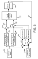
- Figure 3 is a block diagram of a portion of the wheel slip and speed control circuit of controller 214.
- the circuit is preferably embodied as a sequence of computer instructions that configure controller 214.
- Figure 3 illustrates one wheel slip and speed control circuit.
- controller 214 is shown as using the speed signal 311 from one speed sensor of one wheel and motor combination to compensate in block 314 for slippage of that wheel.
- Controller 214 calculates four such compensations for slippage, one compensation for each of the four driven wheels of the vehicle.
- the circuit of Figure 3 can be considered to have four compensator circuits 314, one for compensating each drive motor and wheel, to thereby permit the displacement of each motor, the speed of each motor, and the slip of each motor to be separately and independently controlled.
- Vehicle speed is controlled by using a desired or commanded speed (block 300) provided by input device 220 as a first input and an actual vehicle speed (block 302) provided by the external or internal speed reference 222 as a second input. These two are combined and are applied to the pump 202 (in block 308) to vary the pump displacement accordingly.
- Block 308 represents the vehicle hydrostatic propulsion system, which includes motors 112, 114, 120, 122 and pump 202.
- the two lines entering block 308 represent the signals applied to the motors and the signals applied to the pump to change their displacements.
- Block 309 represents the dynamic response of the vehicle cause by changes in displacement, such as changes in vehicle speed, motor speed and wheel speed and wheel slippage.
- Line 311 represents motor speed signals fed back to controller 314 from the wheel/motor speed sensors 206, 208, 210, 212.
- controller 214 calculates a different displacement setting for pump 202.
- This revised displacement setting is applied as an electrical signal on signal line 216 extending from the controller to the pump to vary its displacement.
- Controller 214 includes a lookup table 306 that is referenced by the microprocessor of controller 214 to retrieve the default pump displacement signal that corresponds to the operator commanded speed. When the operator changes the speed in block 300, controller 214 uses lookup table 306 to determine the corresponding current signal. This signal represents the displacement setting of the pump. Controller 214 applies this signal to pump 202 and the pump sets its displacement as commanded.
- the pump displacement setting provided by lookup table 306 is a default pump displacement setting. This default displacement, however, may not provide exactly the desired speed, due to differences in wheel size or inflation, or differences in the texture of the soil, for example. For that reason, a compensator circuit 304 is provided which compensates for this default pump displacement by adjusting it slightly. These two signals, the default displacement signal from the pump lookup table 306 and the output of the compensator circuit 304 are summed together at summing junction 310 and are transmitted over line 324 to the pump to change its displacement in block 308.
- Compensator circuit 304 calculates the signals that regulate speed to maintain traction and reduce wheel slip. It is preferably embodied as a portion of the control program executed by controller 214. Compensator circuit 304 preferably includes a PID feedback control program stored in the ROM of controller 214 that generates a signal calculated to minimize the difference between the vehicle commanded speed (block 300) and the vehicle actual speed (block 302). This difference is provided to compensator circuit 304 on line 326.
- compensator circuit 304 is not limited to a PID feedback control algorithm but may include additional or alternative logic to compensate for other vehicle dynamic factors such as unique operating conditions, non-linear response characteristics, and unstable conditions in which a standard PID feedback control program alone will not work.
- Each wheel may slip.
- Slipping in this sense is defined as the wheel not turning at the same speed as the vehicle is moving across the ground. Not all slip is bad, however. In agricultural tractors, for example, a certain limited amount of slip permits each wheel to transfer more power to the ground. Thus, “reducing slip” should not be understood as eliminating it, since a residual slip may be beneficial.
- wheel slip Whether or not the vehicle is at the target or command speed, wheel slip needs to be controlled (or prevented, depending upon the application).
- the function of reducing wheel slip is the second function provided by controller 214. This capability is also illustrated in Figure 3.
- Each wheel is equipped with a speed sensor that generates a signal indicative of the speed of rotation of the wheel ( Figure 2).
- Controller 214 monitors the speed of rotation of each wheel, compares it with the actual speed (block 302) of the vehicle (at comparison block 312) and uses this comparison as an input to a second compensator circuit 314.
- the second compensator circuit 314 preferably includes a PID feedback control loop to determine the proper compensation.
- the second compensator circuit and its PID control loop are configured to individually the wheel's specific displacement to reduce or eliminate this slippage.
- Slippage means the difference between a wheel's rotational speed (the ground speed that should result from a wheel rotating at the rotational speed) with the ground speed of the vehicle. While only one block is illustrated in Figure 3, there are four such blocks in actuality, one for each of the driven wheels of the vehicle. Controller 214 is therefore configured to calculate and control wheels slip for each of the four wheels independently.
- controller 214 combines a default motor speed calculated for each motor using motor lookup table 316 with a compensation signal for each motor generated by second compensator circuit 314, at summing junction 320 and applies this combined signal to each motor over line 322.
- the signal generated by comparison block 312 When the wheel rotates with slippage, the signal generated by comparison block 312 will indicate an actual speed difference between the actual speed of the vehicle (block 302) and the speed of the wheel (line 311). If there is no wheel slippage, the signal generated by comparison block 312 will be zero.
- controller 214 is configured to control wheel slip using compensator circuit 314. This may require maintaining a predetermined amount of wheel slip determined to be most efficient for vehicle operation, or it may require eliminating wheel slip altogether.
- controller 214 takes the commanded vehicle speed (block 300) and looks up a corresponding value for the default displacement of the motor in motor current lookup table 316.
- the table is called a motor current lookup table, because in the preferred embodiment the motor changes its displacement proportionate to the current applied to signal line 216. Controller 214 then applies the signal it looks up in table 316 to the motor in block 308 to set its specific displacement.
- controller 214 senses this slippage and generates in second compensator circuit 314 a secondary displacement signal that is summed together with the default displacement signal generated by the lookup table (block 316).
- the default and the secondary motor displacement values are summed in summing junction 320 and are then provided as a combined signal to the motors in block 308. It is this secondary displacement signal calculated by the second compensator circuit 314 that adjusts the default motor displacement in order to control wheel slip.
- the steps of looking up a default motor displacement signal (block 316) and calculating a compensating second motor displacement signal (block 314) are performed independently for each wheel and motor combination.
- the secondary displacement signal calculated in block 314 is selected to reduce the slippage, preferably by reducing the torque applied by the slipping motor to its associated wheel.
- controller 214 calculates a secondary displacement signal that (when combined with the default value provided by the lookup table in block 316) will reduce the torque generated by the motor that is connected to the slipping wheel. By reducing the torque, the wheel is no longer driven hard enough to slip, and eventually regains good contact with the ground.
- controller 214 in block 314 reduces the specific displacement of the motor connected to the slipping wheel.
- each volume of fluid passing through the motor will cause it to rotate more (i.e. through more revolutions or a greater angle). If the specific displacement of the motor is reduced by half, for example, the motor will rotate twice as many turns as it would for the same volume of fluid passing therethrough.
- the slipping motor's resistance to fluid flow increases significantly when the specific displacement is reduced.
- the fluid output of the pump in response, follows the path of least resistance and is conducted through the other three motors instead of passing through the slipping motor.
- the compensator circuit 304 compensates for these fluctuations in vehicle speed above the target or command speed 300, and decreases the specific displacement of the pump accordingly.
- the system individually control the displacement of each wheel motor in response to slipping sensed at each wheel, it also automatically corrects the displacement of pump 202 to compensate for any such changed motor displacement that results in the vehicle speeding up or slowing down.
- the system therefore automatically reduces the specific displacement of pump 202 when one or more wheels slip in order to maintain the vehicle at a constant velocity.
- the compensator circuit 304 automatically responds to this reduction in actual vehicle speed 302 by increasing the displacement of pump 202 accordingly.
- the system automatically increases the specific displacement of the pump when a previously slipping wheel ceases slipping to maintain the vehicle at a constant velocity.
- controller 214 is configured to monitor the speed of the wheels and to independently control their speeds and hence their slip by varying the displacement of each individual motor/wheel pair. Controller 214 controls slip by monitoring the speed of rotation of each wheel and varying the displacement of the motor that is driving the slipping wheel, and varying the displacement of the pump and the other drive wheel motors to compensate for the changes in the displacement of the motor driving the slipping wheel.
- controller 214 is configured to "power turn” (turned by skidding the wheels) the combine. This operational requirement is satisfied by varying the displacement of the hydraulic motors.
- Controller 214 is also configured to prevent the wheels from locking.
Landscapes
- Engineering & Computer Science (AREA)
- General Engineering & Computer Science (AREA)
- Mechanical Engineering (AREA)
- Life Sciences & Earth Sciences (AREA)
- Environmental Sciences (AREA)
- Chemical & Material Sciences (AREA)
- Combustion & Propulsion (AREA)
- Transportation (AREA)
- Control Of Fluid Gearings (AREA)
- Arrangement And Driving Of Transmission Devices (AREA)
- Arrangement And Mounting Of Devices That Control Transmission Of Motive Force (AREA)
Abstract
Description
- The invention relates to agricultural harvesting machines, such as combines, and a method and an apparatus for controlling their ground drive system. More particularly, it relates to a four-wheel drive system comprising variable displacement motors coupled to the wheels.
- Agricultural combines typically have two driven wheels to propel them through the field. The use of two driven wheels limits their performance. With only two driven wheels, combines are prone to slip. To avoid this problem, prior art combines were designed that use a four wheel drive arrangement in which hydraulic fluid from a hydraulic pump is directed to a single motor coupled to two front wheels to drive the front wheels and fluid is also directed to two motors, each motor driving a single rear wheel. This arrangement required the use of a flow splitter circuit that divides the output of the flow between the front wheels' drive motor and the rear wheels' drive motors. The flow splitting circuit was designed to insure that some flow was forced though the front drive motor as well as through the two rear drive motors. In this fashion, if a front wheel slipped, all the hydraulic fluid would not be directed through the front drive motor and bypass the rear drive motors. Instead, and due to the arrangement of the splitter, at least a portion of the flow would be forced through the rear drive motors. By dividing the flow and insuring that at least a portion of the flow would go through both the front motor and the rear motors even when there was slippage of a wheel, slippage of a single wheel would not cause the combine to immediately stop moving, since at least some fluid would continue to drive other motors coupled to wheels that have good ground contact.
- This system, however, has drawbacks. It requires the use of a hydro-mechanical flow splitter. Furthermore, it still permitted both front wheels to be disabled as soon as one of them started slipping and for both rear wheels to be disabled as soon as one of them started slipping.
- It is an object of this invention to provide a combine with an improved anti-slip drive system.
- It is an object of this invention to provide a drive system that can isolate any individual drive wheel that begins slipping.
- It is an object of this invention to prevent the slippage of a wheel by controlling the specific displacement of the motor that drives the slipping wheel.
- It is an object of this invention to prevent the slippage of a wheel by reducing the torque provided by the motor driving that wheel.
- These and other objects of the invention will become clear upon reading the following summary and detailed description of a preferred embodiment of the invention.
- According to one aspect of the present invention, a method is provided for controlling a self-propelled agricultural harvesting machine comprising a chassis, an engine and a ground drive system,
the ground drive system including a variable displacement hydraulic pump coupled to the engine, front and rear variable displacement hydraulic motors coupled together in parallel to one another and coupled in series with the hydraulic pump, front and rear ground-engaging wheels, each coupled to an associate one of the front and rear hydraulic motors, front and rear speed sensors, each sensor disposed to sense the rotational velocity of a corresponding one of the front and rear motors or a corresponding one of the front and rear wheels, a means for determining the ground speed of the vehicle, and an electronic controller coupled to the hydraulic pump, the hydraulic motors, the speed sensors and the ground speed determining means,
the method comprising the steps of: - determining the actual ground speed of the vehicle;
- retrieving a first wheel speed from one of the sensors;
- comparing the first retrieved wheel speed with a reference speed, derived from the determined actual ground speed;
- reducing the torque applied by the motor associated with said one of the speed sensors based upon the results of the step of comparing the first speed in order to limit slippage of the wheel coupled to the motor;
- redetermining the actual ground speed of the vehicle;
- retrieving a second wheel speed from said one of the sensors after the step of reducing the torque;
- comparing the second retrieved speed with a reference speed, derived from the redetermined actual ground speed; and
- increasing the torque applied by the motor associated with said one of the speed sensors based upon the results of the step of comparing the second speed.
- According to a second aspect of the invention, a self-propelled agricultural harvesting machine is provided, the machine comprising a chassis, an engine and a ground drive system,
the ground drive system including a variable displacement hydraulic pump coupled to the engine, front and rear variable displacement hydraulic motors coupled together in parallel to one another and coupled in series with the hydraulic pump, front and rear ground-engaging wheels, each coupled to an associate one of the front and rear hydraulic motors, front and rear speed sensors, each sensor disposed to sense the rotational velocity of a corresponding one of the front and rear motors or a corresponding one of the front and rear wheels, a means for determining the ground speed of the vehicle, and an electronic controller coupled to the hydraulic pump, the hydraulic motors, the speed sensors and the ground speed determining means,
characterised in that the ground drive system comprises no flow dividers disposed between the hydraulic pump and the hydraulic motors to throttle the flow of hydraulic fluid; and
the controller is configured to limit the slippage of each of the wheels individually by controlling the specific displacement of the hydraulic motors coupled to said each of the wheels. - The plurality of wheels may include four wheels, the plurality of motors include four motors and the plurality of sensors include four sensors. The electronic controller may be configured to independently control the rotational speed and direction of the plurality of hydraulic motors. The pump may be an overcentre pump. The electronic controller may calculate the pump displacements and the motor displacements to satisfy the operational requirements. The operational requirements may be to prevent the wheels from slipping, two prevent the wheels from locking, or to power turn the vehicle.
- An embodiment of the invention will now be described in further detail, by way of example only, with reference to the accompanying drawings, wherein:
- Figure 1 is a side schematic view of an agricultural combine having a hydraulic ground wheel drive system;
- Figure 2 is a schematic diagram of the ground wheel drive system of the combine of Figure 1 including a variable displacement pump, four variable displacement motors, and an electronic controller configured to control the pump and motors in accordance with an internal control program; and
- Figure 3 is a block diagram of a portion of the slip control and speed control circuitry of the electronic controller.
- Referring to Figures 1 and 2, a work vehicle is illustrated, shown as an
agricultural combine 100. The combine has achassis 102 on which anengine 104 is mounted. - Two
front wheels hydraulic motors 112 and 114 to which they are coupled. - Two
rear wheels hydraulic motors - The front and rear wheels are ground-engaging wheels that are coupled to the chassis both to drive the combine and to support the weight of the combine as it travels over the ground.
- A
header 124 is mounted to the front of the chassis, extending forward from the front of the chassis to harvest agricultural crops. - A
rotor 126 is mounted centrally in the chassis, and extends longitudinally with respect to the vehicle. The rotor is disposed to mechanically engage the harvested agricultural crop material as it rotates to thereby separate grains or seeds in the harvested agricultural crops from associated leaves and stems. - A
grain tank 130 is mounted on the chassis and is disposed to receive the grains or seeds threshed by the header. -
Rotor 126 is driven by adrive system 132 that is coupled to the rearward end of the rotor. Thedrive system 132 includeshydraulic pump 134 that is coupled to and driven by the engine,hydraulic motor 136 that is fluidly coupled to and driven bypump 134, a planetary gear arrangement, a geartrain coupling engine 104 to the pump and the planetary gear arrangement, andgearbox 138 that drives combinerotor 126. - Figure 2 illustrates the ground
wheel drive system 200 of the combine. Groundwheel drive system 200 includes a variable displacementhydraulic pump 202 that is coupled to and driven byengine 104, four variable displacementhydraulic motors pump 202, four motor (or wheel)speed sensors electronic controller 214 that is coupled topump 202, tomotors wheel speed sensors controller 214 are discussed below. Any capability or functionality that is attributed to the controller herein is provided by an integral control program stored incontroller 214 to control its operation. -
Hydraulic pump 202 is a bidirectional pump that has a variable displacement. Its displacement can be varied electronically by applying an electrical signal proportional to the desired displacement toelectrical signal line 216.Electrical signal line 216 is coupled to and betweencontroller 214 andpump 202.Controller 214 is configured to generate an electrical signal and apply that signal to line 216 to change the specific displacement ofpump 202. In a preferred embodiment,controller 214 generates a current signal in which the magnitude of the current is proportional to the desired displacement of the pump.Controller 214 applies this signal toline 216 andpump 202 responsively changes its specific displacement. The manner in whichcontroller 214 changes the displacement ofpump 202 to reduce wheel slip is discussed below in greater detail. -
Hydraulic motors wheels electrical signal line 218 that is coupled to and between that motor andcontroller 214.Controller 214 transmits a signal indicative of a desired motor displacement to each motor over its associatedsignal line 218. Upon receipt of this signal, the motor responsively changes its specific displacement. The manner in whichcontroller 214 generates and transmits this signal is discussed below in greater detail. -
Sensors controller 214. They generate a speed signal that is proportional to the speed of rotation of their associated wheels or motors and transmit that signal tocontroller 214. In the preferred embodiment, the sensors are integral with the motors and generate a train of electrical pulses, each such pulse indicating a predetermined fractional rotation of the motor. As the motor rotates at a higher velocity, the rate at which the pulses are generated and transmitted tocontroller 214 increases proportionately. -
Electronic controller 214 includes a digital microprocessor coupled to a ROM memory, a RAM memory and an input/output (I/O) circuit, all coupled together over a digital communications bus in a conventional manner. The ROM memory stores the control program that controls the operation of the microprocessor to function in accordance with the description herein. The RAM memory is used primarily as a dynamic temporary storage space for values generated by the microprocessor. The I/O circuit includes drivers that receive digital signals from the microprocessor and convert them into the signals that are applied to the pump and motors. The I/O circuit also includes signal conditioning circuitry that receives signals from the devices (such as the sensors) and conditions it for processing by the microprocessor - A command
speed input device 220 is coupled tocontroller 214 and is manually operable by the machine operator to change the command speed of the vehicle. The input device may be a quadrant lever, a switch or plurality of switches, and may include a shaft encoder, a potentiometer or the like to indicate tocontroller 214 that the operator desires to change the commanded speed. When the operator manipulatesinput device 220,controller 214 senses a change in the electrical signal generated by the input device and changes the commanded speed accordingly. - An external or
internal speed reference 222 is also coupled tocontroller 214 to indicate the actual speed of the vehicle. This device may include a satellite navigation receiver such as a GPS receiver. It may also include a ground reflective radar sensor that determines vehicle velocity by way of a radar signal reflected off the ground.Reference 222 transmits a signal indicative of the ground speed of the vehicle tocontroller 214, which derives the speed of the vehicle from the signal indicative of ground speed and uses that speed in the manner described below. - Alternatively,
controller 214 may derive the actual vehicle speed using an internal reference, such as a mathematical model of the vehicle. In such instances,controller 214 is configured to determine the speed of the vehicle by deriving it from one or more of the wheel speed sensors. - The hydraulic circuit coupling the motors and the pump is a series/parallel circuit. Each motor is coupled in series to the pump to form an individual series hydraulic circuit, such that fluid from the pump outlet passes into a hydraulic fluid inlet of the motor, through that motor, out the hydraulic fluid outlet of the motor and back into the hydraulic fluid inlet of the pump. This relationship is true of all the motors with respect to the pump.
- At the same time, the motors are connected in parallel with each other. The hydraulic fluid inlets of all the motors are coupled together and fed in common by the hydraulic fluid outlet of the pump, and the hydraulic fluid outlets of all the motors are coupled together to form a common return line to the hydraulic fluid inlet of the pump. The terms "inlet" and "outlet" are figurative; in the preferred embodiment, since the flow can change direction. Thus, an inlet with flow in one direction would become an outlet when flow travels in the other direction.
- Since the motors are connected in parallel to the pump, the pump simultaneously supplies fluid to all four of the hydraulic motors. There is no flow splitter disposed between the pump and the motors to divide the flow in specific proportions in the event. If it were not for the slip control features of the present invention, a wheel that loses contact with the ground could overspeed, consume all the available hydraulic fluid. The other motors would soon slow to a halt, and the vehicle would be stranded. The purpose of the slip control is to prevent such an overspeed condition by reducing the torque generated by a slipping wheel until it regains good contact with the ground and stops slipping, as shown in Figure 3.
- The motors are connected in parallel with no load-balancing or load-shifting valves disposed between the pump an the motor. In prior art devices, such valves were provided to insure (for example) that when one wheel and motor begins to slip and spin, all the hydraulic fluid flow did not go through that motor, thereby stalling the other wheels. In the present configuration, the electronic controller is configured to sense such conditions and to responsively and independently regulate the flow of hydraulic fluid to each motor by independently controlling the displacement of that motor, as will be described below in the context of the system's anti-slip capabilities.
- Figure 3 is a block diagram of a portion of the wheel slip and speed control circuit of
controller 214. The circuit is preferably embodied as a sequence of computer instructions that configurecontroller 214. - For convenience, Figure 3 illustrates one wheel slip and speed control circuit. There are four such circuits, one for each
wheel motor sensor controller 214 is shown as using thespeed signal 311 from one speed sensor of one wheel and motor combination to compensate inblock 314 for slippage of that wheel.Controller 214 calculates four such compensations for slippage, one compensation for each of the four driven wheels of the vehicle. The circuit of Figure 3 can be considered to have fourcompensator circuits 314, one for compensating each drive motor and wheel, to thereby permit the displacement of each motor, the speed of each motor, and the slip of each motor to be separately and independently controlled. - Vehicle speed is controlled by using a desired or commanded speed (block 300) provided by
input device 220 as a first input and an actual vehicle speed (block 302) provided by the external orinternal speed reference 222 as a second input. These two are combined and are applied to the pump 202 (in block 308) to vary the pump displacement accordingly. -
Block 308 represents the vehicle hydrostatic propulsion system, which includesmotors lines entering block 308 represent the signals applied to the motors and the signals applied to the pump to change their displacements.Block 309 represents the dynamic response of the vehicle cause by changes in displacement, such as changes in vehicle speed, motor speed and wheel speed and wheel slippage.Line 311 represents motor speed signals fed back tocontroller 314 from the wheel/motor speed sensors - As the vehicle speeds up or slows down, the reference or actual speed (block 302) changes, and
controller 214 calculates a different displacement setting forpump 202. This revised displacement setting is applied as an electrical signal onsignal line 216 extending from the controller to the pump to vary its displacement. -
Controller 214 includes a lookup table 306 that is referenced by the microprocessor ofcontroller 214 to retrieve the default pump displacement signal that corresponds to the operator commanded speed. When the operator changes the speed inblock 300,controller 214 uses lookup table 306 to determine the corresponding current signal. This signal represents the displacement setting of the pump.Controller 214 applies this signal to pump 202 and the pump sets its displacement as commanded. The pump displacement setting provided by lookup table 306 is a default pump displacement setting. This default displacement, however, may not provide exactly the desired speed, due to differences in wheel size or inflation, or differences in the texture of the soil, for example. For that reason, acompensator circuit 304 is provided which compensates for this default pump displacement by adjusting it slightly. These two signals, the default displacement signal from the pump lookup table 306 and the output of thecompensator circuit 304 are summed together at summingjunction 310 and are transmitted overline 324 to the pump to change its displacement inblock 308. -
Compensator circuit 304 calculates the signals that regulate speed to maintain traction and reduce wheel slip. It is preferably embodied as a portion of the control program executed bycontroller 214.Compensator circuit 304 preferably includes a PID feedback control program stored in the ROM ofcontroller 214 that generates a signal calculated to minimize the difference between the vehicle commanded speed (block 300) and the vehicle actual speed (block 302). This difference is provided tocompensator circuit 304 online 326. - It should be understood that
compensator circuit 304 is not limited to a PID feedback control algorithm but may include additional or alternative logic to compensate for other vehicle dynamic factors such as unique operating conditions, non-linear response characteristics, and unstable conditions in which a standard PID feedback control program alone will not work. - Each wheel may slip. "Slipping" in this sense is defined as the wheel not turning at the same speed as the vehicle is moving across the ground. Not all slip is bad, however. In agricultural tractors, for example, a certain limited amount of slip permits each wheel to transfer more power to the ground. Thus, "reducing slip" should not be understood as eliminating it, since a residual slip may be beneficial.
- Whether or not the vehicle is at the target or command speed, wheel slip needs to be controlled (or prevented, depending upon the application). The function of reducing wheel slip is the second function provided by
controller 214. This capability is also illustrated in Figure 3. - Each wheel is equipped with a speed sensor that generates a signal indicative of the speed of rotation of the wheel (Figure 2).
Controller 214 monitors the speed of rotation of each wheel, compares it with the actual speed (block 302) of the vehicle (at comparison block 312) and uses this comparison as an input to asecond compensator circuit 314. Thesecond compensator circuit 314 preferably includes a PID feedback control loop to determine the proper compensation. The second compensator circuit and its PID control loop are configured to individually the wheel's specific displacement to reduce or eliminate this slippage. "Slippage" means the difference between a wheel's rotational speed (the ground speed that should result from a wheel rotating at the rotational speed) with the ground speed of the vehicle. While only one block is illustrated in Figure 3, there are four such blocks in actuality, one for each of the driven wheels of the vehicle.Controller 214 is therefore configured to calculate and control wheels slip for each of the four wheels independently. - To control slippage,
controller 214 combines a default motor speed calculated for each motor using motor lookup table 316 with a compensation signal for each motor generated bysecond compensator circuit 314, at summingjunction 320 and applies this combined signal to each motor overline 322. - When the wheel rotates with slippage, the signal generated by
comparison block 312 will indicate an actual speed difference between the actual speed of the vehicle (block 302) and the speed of the wheel (line 311). If there is no wheel slippage, the signal generated bycomparison block 312 will be zero. - As mentioned above,
controller 214 is configured to control wheel slip usingcompensator circuit 314. This may require maintaining a predetermined amount of wheel slip determined to be most efficient for vehicle operation, or it may require eliminating wheel slip altogether. - To set the displacement of each motor (which controls motor speed and wheel slippage),
controller 214 takes the commanded vehicle speed (block 300) and looks up a corresponding value for the default displacement of the motor in motor current lookup table 316. The table is called a motor current lookup table, because in the preferred embodiment the motor changes its displacement proportionate to the current applied to signalline 216.Controller 214 then applies the signal it looks up in table 316 to the motor inblock 308 to set its specific displacement. - If any wheel slips, however,
controller 214 senses this slippage and generates in second compensator circuit 314 a secondary displacement signal that is summed together with the default displacement signal generated by the lookup table (block 316). The default and the secondary motor displacement values are summed in summingjunction 320 and are then provided as a combined signal to the motors inblock 308. It is this secondary displacement signal calculated by thesecond compensator circuit 314 that adjusts the default motor displacement in order to control wheel slip. - The steps of looking up a default motor displacement signal (block 316) and calculating a compensating second motor displacement signal (block 314) are performed independently for each wheel and motor combination. There may be a single motor displacement lookup table, or there may be multiple lookup tables, one for each wheel and motor pair, depending upon the type of motors, and the size of the wheels, for example.
- The secondary displacement signal calculated in
block 314 is selected to reduce the slippage, preferably by reducing the torque applied by the slipping motor to its associated wheel. Inblock 314,controller 214 calculates a secondary displacement signal that (when combined with the default value provided by the lookup table in block 316) will reduce the torque generated by the motor that is connected to the slipping wheel. By reducing the torque, the wheel is no longer driven hard enough to slip, and eventually regains good contact with the ground. - In the arrangement shown in Figure 2, there are four motors connected in parallel with one another and collectively connected in series with the pump. To reduce the torque applied to a motor that is slipping,
controller 214 inblock 314 reduces the specific displacement of the motor connected to the slipping wheel. By reducing the specific displacement, each volume of fluid passing through the motor will cause it to rotate more (i.e. through more revolutions or a greater angle). If the specific displacement of the motor is reduced by half, for example, the motor will rotate twice as many turns as it would for the same volume of fluid passing therethrough. - In effect, the slipping motor's resistance to fluid flow increases significantly when the specific displacement is reduced. The fluid output of the pump, in response, follows the path of least resistance and is conducted through the other three motors instead of passing through the slipping motor.
- This increased flow through the other three motors (whose specific displacement has not been changed) will cause them to rotate faster. This faster rotation would normally cause the vehicle to speed up. As described above, however, the
compensator circuit 304 compensates for these fluctuations in vehicle speed above the target orcommand speed 300, and decreases the specific displacement of the pump accordingly. - Thus, not only does the system individually control the displacement of each wheel motor in response to slipping sensed at each wheel, it also automatically corrects the displacement of
pump 202 to compensate for any such changed motor displacement that results in the vehicle speeding up or slowing down. The system therefore automatically reduces the specific displacement ofpump 202 when one or more wheels slip in order to maintain the vehicle at a constant velocity. - When the speed of the slipping wheel responds to the reduction in motor torque and again engages the ground, the difference between the actual vehicle speed and the speed of the wheel decreases toward zero, and the secondary motor displacement signal likewise decreases toward zero. The result is that the specific displacement of the motor driving the formerly slipping wheel increases, and approaches the default value. By increasing the specific displacement of the motor, the motor torque is increased and the fluid flow through the motor also increases.
- When the specific displacement of the slipping motor is increased, its resistance to fluid flow is decreased and more fluid begins to pass through the previously slipping motor. This increased flow through the motor reduces the flow available to the other three motors, and the vehicle will tend to slow down. The
compensator circuit 304 automatically responds to this reduction inactual vehicle speed 302 by increasing the displacement ofpump 202 accordingly. - Thus the system automatically increases the specific displacement of the pump when a previously slipping wheel ceases slipping to maintain the vehicle at a constant velocity.
- In the preferred embodiment discussed above,
controller 214 is configured to monitor the speed of the wheels and to independently control their speeds and hence their slip by varying the displacement of each individual motor/wheel pair.Controller 214 controls slip by monitoring the speed of rotation of each wheel and varying the displacement of the motor that is driving the slipping wheel, and varying the displacement of the pump and the other drive wheel motors to compensate for the changes in the displacement of the motor driving the slipping wheel. - In a similar fashion,
controller 214 is configured to "power turn" (turned by skidding the wheels) the combine. This operational requirement is satisfied by varying the displacement of the hydraulic motors. -
Controller 214 is also configured to prevent the wheels from locking. - It will be obvious to those skilled in the art that various changes may be made without departing from the scope of the invention as defined by the claims and the invention is not considered to be limited to the embodiment illustrated in the drawings and described in the specification.
Claims (17)
- A method for controlling a self-propelled agricultural harvesting machine (100) comprising a chassis (102), an engine (104) and a ground drive system (104),
the ground drive system (200) including a variable displacement hydraulic pump (202) coupled to the engine (104), front and rear variable displacement hydraulic motors (112, 114, 120, 122) coupled together in parallel to one another and coupled in series with the hydraulic pump (202), front and rear ground-engaging wheels (108, 110, 116, 118), each coupled to an associate one of the front and rear hydraulic motors (112, 114, 120, 122), front and rear speed sensors (206, 208, 210, 212), each sensor disposed to sense the rotational velocity of a corresponding one of the front and rear motors (112, 114, 120, 122) or a corresponding one of the front and rear wheels (108, 110, 116, 118), a means (222) for determining the ground speed (302) of the vehicle, and an electronic controller (214) coupled to the hydraulic pump (202), the hydraulic motors (112, 114, 120, 122), the speed sensors (206, 208, 210, 212) and the ground speed determining means (222),
the method comprising the steps of:determining the actual ground speed (302) of the vehicle;retrieving a first wheel speed (311) from one of the sensors (206, 208, 210, 212);comparing the first retrieved wheel speed (311) with a reference speed, derived from the determined actual ground speed (302);reducing the torque applied by the motor associated with said one of the speed sensors (206, 208, 210, 212) based upon the results of the step of comparing the first speed (311) in order to limit slippage of the wheel coupled to the motor;redetermining the actual ground speed (302) of the vehicle;retrieving a second wheel speed (311) from said one of the sensors (206, 208, 210, 212) after the step of reducing the torque;comparing the second retrieved speed with a reference speed, derived from the redetermined actual ground speed (302); andincreasing the torque applied by the motor associated with said one of the speed sensors (206, 208, 210, 212) based upon the results of the step of comparing the second speed. - A method according to claim 1, characterised in that the steps of comparing the first retrieved speed (311) and reducing the torque are repeated one or more times before executing the steps of comparing the second retrieved speed (311) and increasing the torque.
- A method according to claim 1 or 2, characterised in that the steps of comparing the second retrieved speed (311) and increasing the torque are repeated one or more times.
- A method according to any of the preceding claims, characterised in that the step of reducing the torque includes the step of reducing specific displacement of the motor (112/114/120/122) associated with said one of the speed sensors (206, 208, 210, 212).
- A method according to any of the preceding claims, characterised in that the step of increasing the torque includes the step of increasing specific displacement of the motor (112/114/120/122) associated with said one of the speed sensors (206, 208, 210, 212).
- A method according to any of the preceding claims, characterised in that the steps of reducing and increasing the torque comprise:using PID feedback control to reduce or eliminate the difference between the retrieved wheel speed (311) and the actual ground speed (302).
- A method according to any of the preceding claims, characterised in that the steps above are repeated for each of the other wheels (108, 110, 116, 118) and associate hydraulic motors (112, 114, 120, 122).
- A method according to any of the preceding claims, characterised in that the step of determining the ground speed (302) is preceded by the steps of:deriving a default pump displacement from a commanded ground speed (300); andderiving default motor displacements from the commanded ground speed (300) for each of the motors (112, 114, 120, 122); andapplying the derived default displacements to the pump (202) and the motors (112, 114, 120, 122).
- A method according to claim 8, characterised in that said steps of deriving a default pump displacement and deriving default motor displacements comprise:using a pump lookup table (306); andusing one or more motor lookup tables (316).
- A method according to any of the preceding claims, characterised in that it comprises the further step of:automatically reducing or increasing the specific displacement of the pump (202) when the specific displacement of one of the motors (112, 114, 120, 122) is reduced or increased respectively, in order to maintain the machine (100) at a constant ground speed (300).
- A method according to according to claim 10, characterised in that the step of automatically reducing or increasing the specific displacement of the pump (202) comprises the substeps of:comparing the commanded ground speed (300) to the determined actual ground speed (302);deriving a pump displacement compensation for the pump (202) based upon the results of the step of comparing the commanded ground speed (300);applying the pump displacement compensation to the pump (202).
- A method according to claim 11, characterised in that the step of deriving a pump displacement compensation comprises:using PID feedback control for minimising the difference between the commanded ground speed (300) and the actual ground speed (302).
- A method according to any of the preceding claims, characterised in that the steps of determining and redetermining the actual ground speed (302) comprises:using a ground-reflective radar (222), or a radio navigation receiver, such as a satellite navigation receiver responsive to signals transmitted by a navigation satellite.
- A method according to any of the preceding claims, characterised in that the ground drive system (200) comprises no flow dividers disposed between the hydraulic pump (202) and the hydraulic motors (112, 114, 120, 122) to throttle the flow of hydraulic fluid.
- A method according to any of the preceding claims, characterised in that the agricultural harvesting machine is a combine harvester (100) further comprising a rotor (126) configured to thresh agricultural plant matter, the rotor being coupled to the engine (104) to be driven thereby.
- A self-propelled agricultural harvesting machine (100) comprising a chassis (102), an engine (104) and a ground drive system (200),
the ground drive system (200) including a variable displacement hydraulic pump (202) coupled to the engine (104), front and rear variable displacement hydraulic motors (112, 114, 120, 122) coupled together in parallel to one another and coupled in series with the hydraulic pump (202), front and rear ground-engaging wheels (108, 110, 116, 118), each coupled to an associate one of the front and rear hydraulic motors (112, 114, 120, 122), front and rear speed sensors (206, 208, 210, 212), each sensor disposed to sense the rotational velocity of a corresponding one of the front and rear motors (112, 114, 120, 122) or a corresponding one of the front and rear wheels (108, 110, 116, 118), a means (222) for determining the ground speed (302) of the vehicle, and an electronic controller (214) coupled to the hydraulic pump (202), the hydraulic motors (112, 114, 120, 122), the speed sensors (206, 208, 210, 212) and the ground speed determining means (222),
characterised in that:the ground drive system (200) comprises no flow dividers disposed between the hydraulic pump and the hydraulic motors (112, 114, 120, 122) to throttle the flow of hydraulic fluid; andthe controller (214) is configured to limit the slippage of each of the wheels (108, 110, 116, 118) individually by controlling the specific displacement of the hydraulic motors (112, 114, 120, 122) coupled to said each of the wheels (108, 110, 116, 118). - An agricultural harvesting machine according to claim 16, characterised in that the controller (214) is configured to control the specific displacement of the hydraulic pump in order to maintain the ground speed (302) of the machine (100) under circumstances where the specific displacement of one or more of the hydraulic motors (112, 114, 120, 122) is changed to limit the slippage of the wheel (108/110/116/118) coupled thereto.
Applications Claiming Priority (1)
| Application Number | Priority Date | Filing Date | Title |
|---|---|---|---|
| US11/119,523 US7121374B1 (en) | 2005-04-30 | 2005-04-30 | Four-wheel drive combine with slip control |
Publications (2)
| Publication Number | Publication Date |
|---|---|
| EP1716737A1 true EP1716737A1 (en) | 2006-11-02 |
| EP1716737B1 EP1716737B1 (en) | 2008-05-14 |
Family
ID=36756719
Family Applications (1)
| Application Number | Title | Priority Date | Filing Date |
|---|---|---|---|
| EP06113318A Expired - Lifetime EP1716737B1 (en) | 2005-04-30 | 2006-04-28 | A four wheel drive harvester with slip control. |
Country Status (4)
| Country | Link |
|---|---|
| US (3) | US7121374B1 (en) |
| EP (1) | EP1716737B1 (en) |
| AT (1) | ATE394917T1 (en) |
| DE (1) | DE602006001147D1 (en) |
Cited By (3)
| Publication number | Priority date | Publication date | Assignee | Title |
|---|---|---|---|---|
| EP2009329A1 (en) | 2007-06-27 | 2008-12-31 | CLAAS Selbstfahrende Erntemaschinen GmbH | Electronic control for the hydrostatic drive unit of a vehicle |
| WO2009106169A1 (en) * | 2008-02-29 | 2009-09-03 | Robert Bosch Gmbh | Method for determining a wheel reference speed of a wheel on a vehicle having hydrostatic drive, and device for determining a wheel reference speed of a wheel of a vehicle having hydrostatic drive |
| EP2942227A3 (en) * | 2014-03-03 | 2016-07-20 | Deere & Company | Traction control method and apparatus for a work vehicle with independent drives |
Families Citing this family (17)
| Publication number | Priority date | Publication date | Assignee | Title |
|---|---|---|---|---|
| JP2007127174A (en) * | 2005-11-02 | 2007-05-24 | Hitachi Constr Mach Co Ltd | Work vehicle travel control apparatus and travel control method |
| US7849952B2 (en) * | 2006-08-24 | 2010-12-14 | Macdon Industries Ltd | Tractor with two engine settings |
| JP5362958B2 (en) * | 2007-01-24 | 2013-12-11 | 株式会社小松製作所 | Hydraulic drive |
| DE102007053320A1 (en) * | 2007-11-08 | 2009-05-14 | Agco Gmbh | Transmission synchronization method and apparatus for at least two transmissions |
| CN101480921A (en) * | 2008-01-09 | 2009-07-15 | 三一重工股份有限公司 | Hydraulic power transmission engineering vehicle antiskid method, system as well as leveler |
| US8055411B2 (en) | 2008-10-31 | 2011-11-08 | Caterpillar Inc. | Steering system and method of steering a machine |
| US7748489B2 (en) * | 2008-10-31 | 2010-07-06 | Deere & Company | Agricultural header presence sensor with traction control |
| WO2010082636A1 (en) * | 2009-01-16 | 2010-07-22 | 住友重機械工業株式会社 | Hybrid working machine and method of controlling same |
| US8662212B2 (en) * | 2009-06-04 | 2014-03-04 | Thomas Towles Lawson, Jr. | Four wheel drive system |
| US9067495B2 (en) | 2013-03-15 | 2015-06-30 | Agco Corporation | System and method for operating vehicle drive wheels |
| WO2015085134A1 (en) * | 2013-12-05 | 2015-06-11 | Agco Corporation | Computer program and method for controlling a drive system of an agricultural vehicle |
| US9267245B1 (en) | 2014-10-17 | 2016-02-23 | Wacker Neuson Production Americas Llc | Vibratory compacting roller machine with drum steering |
| DE102017204353A1 (en) * | 2016-04-28 | 2017-11-02 | Robert Bosch Gmbh | Hydrostatic drive and method for controlling the hydrostatic drive |
| BE1025282B1 (en) * | 2017-06-02 | 2019-01-11 | Cnh Industrial Belgium Nv | Carrying capacity of the ground |
| KR20210131319A (en) | 2019-02-22 | 2021-11-02 | 클라크 이큅먼트 컴파니 | Traction Control of Steering Articulated Power Machines |
| US12532794B2 (en) | 2022-12-27 | 2026-01-27 | Cnh Industrial Canada, Ltd. | System and method for controlling an agricultural system based on slip |
| US20250263077A1 (en) * | 2024-02-16 | 2025-08-21 | Cnh Industrial America Llc | Systems and methods for an agricultural vehicle |
Citations (5)
| Publication number | Priority date | Publication date | Assignee | Title |
|---|---|---|---|---|
| US4675819A (en) * | 1983-12-17 | 1987-06-23 | Itt Industries, Inc. | Method for the generation of a vehicle reference speed as a reference value for the control of brake slip and/or traction slip |
| EP0226844A1 (en) * | 1985-12-05 | 1987-07-01 | Hydromatik GmbH | Hydrostatic transmission for motor vehicles with at least two hydromotors with compensating control |
| FR2651729A1 (en) * | 1989-09-12 | 1991-03-15 | Chaneac Andre | Vehicle or machine with at least four driving wheels equipped with an anti-skid system |
| US5016179A (en) * | 1988-07-13 | 1991-05-14 | Knorr-Bremse Ag | Drive slip regulator for motor vehicles |
| FR2693959A1 (en) * | 1992-07-24 | 1994-01-28 | Armef | Automotive terrestrial vehicle with limitation of wheel spin on driven wheel - uses averaging of wheel speeds to determine correction to be applied to wheel that starts to slip |
Family Cites Families (26)
| Publication number | Priority date | Publication date | Assignee | Title |
|---|---|---|---|---|
| DE2707047B2 (en) * | 1977-02-18 | 1979-08-02 | Siemens Ag, 1000 Berlin Und 8000 Muenchen | Arrangement for detecting the skidding or sliding of the wheels of non-axled rail locomotives |
| US4103489A (en) * | 1977-04-15 | 1978-08-01 | Deere & Company | Total power fluid system |
| US4399886A (en) * | 1980-12-09 | 1983-08-23 | Sundstrand Corporation | Controls for variable displacement motor and motors |
| US4818037A (en) * | 1988-05-16 | 1989-04-04 | Hughes Aircraft Company | Method for estimating reference speed and acceleration for traction and anti-skid braking control |
| DE4030653A1 (en) * | 1990-09-28 | 1992-04-02 | Bosch Gmbh Robert | METHOD FOR DETERMINING THE SLOPING ANGLE AND / OR THE SIDE GUIDING FORCE OF A BRAKED VEHICLE |
| US5668724A (en) * | 1990-09-28 | 1997-09-16 | Robert Bosch Gmbh | Method for improving the controllabilty of motor vehicles |
| US5290201A (en) * | 1992-06-11 | 1994-03-01 | Tesker Henry L | Combine with mmoveable body and tandem drive wheels |
| JPH0687348A (en) * | 1992-09-08 | 1994-03-29 | Komatsu Ltd | Vehicle slip detector |
| US5574643A (en) * | 1994-07-15 | 1996-11-12 | Caterpillar Inc. | Traction control for a machine with electronic engine and transmission controls |
| DE19527840B4 (en) * | 1995-07-28 | 2004-09-16 | Siemens Ag | Circuit arrangement for controlling the torque transmitted between the drive wheels of a motor vehicle and the road |
| US5775453A (en) * | 1995-09-20 | 1998-07-07 | Sauer Inc. | Traction control system and method for hydraulically propelled vehicles |
| DE19722148A1 (en) * | 1996-05-28 | 1997-12-04 | Mando Machine Co Ltd | Vehicle traction control device |
| US5860480A (en) * | 1997-04-08 | 1999-01-19 | Caterpillar Inc. | Method and apparatus for determining pitch and ground speed of an earth moving machines |
| GB9711170D0 (en) * | 1997-05-31 | 1997-07-23 | Rover Group | Vehicle steering control |
| DE19734112B4 (en) * | 1997-08-07 | 2007-12-27 | Robert Bosch Gmbh | Method and device for traction control in motor vehicles |
| US6125318A (en) * | 1998-02-12 | 2000-09-26 | The B. F. Goodrich Company | Slip ratio antiskid controller using mu/slip ratio generated velocity reference |
| US6145287A (en) * | 1998-03-05 | 2000-11-14 | Sauer Inc. | Hydrostatic circuit for harvesting machine |
| US6135231A (en) * | 1998-04-27 | 2000-10-24 | Sauer Inc. | Method and means for providing a steer-assist and anti-spin system for hydrostatically propelled vehicles |
| FR2789352B1 (en) * | 1999-02-05 | 2001-04-27 | Poclain Hydraulics Ind | DEVICE FOR TRANSMITTING A MOBILE MACHINE HAVING AT LEAST TWO IN-LINE MOTOR MOVING DEVICES |
| US6283237B1 (en) * | 1999-06-01 | 2001-09-04 | Caterpillar Inc. | Method and apparatus for steering articulated machines using variable speed devices |
| DE19931141B4 (en) * | 1999-07-06 | 2005-03-03 | Sauer-Danfoss Holding Aps | Vehicle drive arrangement |
| DE19956469A1 (en) * | 1999-11-24 | 2001-05-31 | Mannesmann Rexroth Ag | Hydrostatic propulsive drive has braking device that interacts with each motor connected to control unit that activates brake if its associated motor's speed exceeds predetermined threshold |
| US6408972B1 (en) * | 2000-11-17 | 2002-06-25 | Sauer-Danfoss Inc. | Electronic traction control system |
| US6695693B2 (en) * | 2002-06-11 | 2004-02-24 | Case Llc | Combine having a system estimator to monitor hydraulic system pressure |
| US6702666B2 (en) * | 2002-06-11 | 2004-03-09 | Case, Llc | Combine having a system estimator to monitor hydraulic system pressure |
| US6681551B1 (en) * | 2002-07-11 | 2004-01-27 | Deere & Co. | Programmable function control for combine |
-
2005
- 2005-04-30 US US11/119,523 patent/US7121374B1/en not_active Expired - Lifetime
-
2006
- 2006-03-06 US US11/368,918 patent/US7357214B2/en not_active Expired - Lifetime
- 2006-03-06 US US11/368,943 patent/US7172046B2/en not_active Expired - Lifetime
- 2006-04-28 DE DE602006001147T patent/DE602006001147D1/en not_active Expired - Lifetime
- 2006-04-28 EP EP06113318A patent/EP1716737B1/en not_active Expired - Lifetime
- 2006-04-28 AT AT06113318T patent/ATE394917T1/en not_active IP Right Cessation
Patent Citations (5)
| Publication number | Priority date | Publication date | Assignee | Title |
|---|---|---|---|---|
| US4675819A (en) * | 1983-12-17 | 1987-06-23 | Itt Industries, Inc. | Method for the generation of a vehicle reference speed as a reference value for the control of brake slip and/or traction slip |
| EP0226844A1 (en) * | 1985-12-05 | 1987-07-01 | Hydromatik GmbH | Hydrostatic transmission for motor vehicles with at least two hydromotors with compensating control |
| US5016179A (en) * | 1988-07-13 | 1991-05-14 | Knorr-Bremse Ag | Drive slip regulator for motor vehicles |
| FR2651729A1 (en) * | 1989-09-12 | 1991-03-15 | Chaneac Andre | Vehicle or machine with at least four driving wheels equipped with an anti-skid system |
| FR2693959A1 (en) * | 1992-07-24 | 1994-01-28 | Armef | Automotive terrestrial vehicle with limitation of wheel spin on driven wheel - uses averaging of wheel speeds to determine correction to be applied to wheel that starts to slip |
Cited By (6)
| Publication number | Priority date | Publication date | Assignee | Title |
|---|---|---|---|---|
| EP2009329A1 (en) | 2007-06-27 | 2008-12-31 | CLAAS Selbstfahrende Erntemaschinen GmbH | Electronic control for the hydrostatic drive unit of a vehicle |
| RU2469878C2 (en) * | 2007-06-27 | 2012-12-20 | КЛААС Зельбстфаренде Эрнтемашинен ГмбХ | Electronic control device for vehicle drive |
| WO2009106169A1 (en) * | 2008-02-29 | 2009-09-03 | Robert Bosch Gmbh | Method for determining a wheel reference speed of a wheel on a vehicle having hydrostatic drive, and device for determining a wheel reference speed of a wheel of a vehicle having hydrostatic drive |
| US8751132B2 (en) | 2008-02-29 | 2014-06-10 | Robert Bosch Gmbh | Method for ascertaining a wheel reference speed of a wheel on a vehicle having a hydrostatic drive, and device for ascertaining a wheel reference speed of a wheel of a vehicle having a hydrostatic drive |
| EP2942227A3 (en) * | 2014-03-03 | 2016-07-20 | Deere & Company | Traction control method and apparatus for a work vehicle with independent drives |
| US9956874B2 (en) | 2014-03-03 | 2018-05-01 | Deere & Company | Traction control method and apparatus for a work vehicle with independent drives |
Also Published As
| Publication number | Publication date |
|---|---|
| US7121374B1 (en) | 2006-10-17 |
| US20060243511A1 (en) | 2006-11-02 |
| US20060243516A1 (en) | 2006-11-02 |
| EP1716737B1 (en) | 2008-05-14 |
| DE602006001147D1 (en) | 2008-06-26 |
| US7172046B2 (en) | 2007-02-06 |
| US7357214B2 (en) | 2008-04-15 |
| ATE394917T1 (en) | 2008-05-15 |
| US20060243510A1 (en) | 2006-11-02 |
Similar Documents
| Publication | Publication Date | Title |
|---|---|---|
| EP1716737B1 (en) | A four wheel drive harvester with slip control. | |
| US7044257B2 (en) | Drive system of a utility vehicle | |
| US10709061B2 (en) | Electric power equipment | |
| RU2469878C2 (en) | Electronic control device for vehicle drive | |
| US20180196441A1 (en) | Model-based predictive speed control of a harvesting machine | |
| US9796419B2 (en) | Speed and steering control of a hydraulically driven tractor | |
| US9635806B2 (en) | Mower blade speed control system | |
| EP3099156B1 (en) | Automatic load control for self-propelled windrower | |
| US11533844B2 (en) | Load based ground speed control method | |
| CN112005707A (en) | Motor drive-based automatic variable speed control system and device for harvester | |
| US20200352100A1 (en) | Drive System for a Harvester | |
| KR102871987B1 (en) | Speed control system | |
| JP2020018171A (en) | Control device for work vehicle | |
| US9067495B2 (en) | System and method for operating vehicle drive wheels | |
| CN110583216A (en) | Travel control device for harvester and work vehicle | |
| JP2019213502A (en) | Working vehicle | |
| JPH0595725A (en) | Car speed controller for mobile agricultural machine | |
| JP2019213501A (en) | Travel controller for harvester | |
| JPH0595723A (en) | Vehicle speed control device for mobile agricultural machinery | |
| JPH0595724A (en) | Vehicle speed control device for mobile agricultural machinery | |
| JPH0595722A (en) | Car speed controller for combine | |
| JPH0646893B2 (en) | Lawn mower |
Legal Events
| Date | Code | Title | Description |
|---|---|---|---|
| PUAI | Public reference made under article 153(3) epc to a published international application that has entered the european phase |
Free format text: ORIGINAL CODE: 0009012 |
|
| AK | Designated contracting states |
Kind code of ref document: A1 Designated state(s): AT BE BG CH CY CZ DE DK EE ES FI FR GB GR HU IE IS IT LI LT LU LV MC NL PL PT RO SE SI SK TR |
|
| AX | Request for extension of the european patent |
Extension state: AL BA HR MK YU |
|
| RIN1 | Information on inventor provided before grant (corrected) |
Inventor name: HORVAT, BRANKO J. JR. Inventor name: HO, YUN REN Inventor name: BUNDY, JOHN E. Inventor name: JOHNSON, BERNARD |
|
| 17P | Request for examination filed |
Effective date: 20070129 |
|
| 17Q | First examination report despatched |
Effective date: 20070302 |
|
| AKX | Designation fees paid |
Designated state(s): AT BE BG CH CY CZ DE DK EE ES FI FR GB GR HU IE IS IT LI LT LU LV MC NL PL PT RO SE SI SK TR |
|
| AXX | Extension fees paid |
Extension state: YU Payment date: 20070502 Extension state: AL Payment date: 20070502 Extension state: HR Payment date: 20070502 Extension state: MK Payment date: 20070502 Extension state: BA Payment date: 20070502 |
|
| GRAP | Despatch of communication of intention to grant a patent |
Free format text: ORIGINAL CODE: EPIDOSNIGR1 |
|
| GRAS | Grant fee paid |
Free format text: ORIGINAL CODE: EPIDOSNIGR3 |
|
| GRAA | (expected) grant |
Free format text: ORIGINAL CODE: 0009210 |
|
| AK | Designated contracting states |
Kind code of ref document: B1 Designated state(s): AT BE BG CH CY CZ DE DK EE ES FI FR GB GR HU IE IS IT LI LT LU LV MC NL PL PT RO SE SI SK TR |
|
| AX | Request for extension of the european patent |
Extension state: AL BA HR MK YU |
|
| REG | Reference to a national code |
Ref country code: GB Ref legal event code: FG4D |
|
| REG | Reference to a national code |
Ref country code: CH Ref legal event code: EP |
|
| REG | Reference to a national code |
Ref country code: IE Ref legal event code: FG4D Free format text: LANGUAGE OF EP DOCUMENT: FRENCH |
|
| REF | Corresponds to: |
Ref document number: 602006001147 Country of ref document: DE Date of ref document: 20080626 Kind code of ref document: P |
|
| PG25 | Lapsed in a contracting state [announced via postgrant information from national office to epo] |
Ref country code: SI Free format text: LAPSE BECAUSE OF FAILURE TO SUBMIT A TRANSLATION OF THE DESCRIPTION OR TO PAY THE FEE WITHIN THE PRESCRIBED TIME-LIMIT Effective date: 20080514 |
|
| PG25 | Lapsed in a contracting state [announced via postgrant information from national office to epo] |
Ref country code: FI Free format text: LAPSE BECAUSE OF FAILURE TO SUBMIT A TRANSLATION OF THE DESCRIPTION OR TO PAY THE FEE WITHIN THE PRESCRIBED TIME-LIMIT Effective date: 20080514 Ref country code: ES Free format text: LAPSE BECAUSE OF FAILURE TO SUBMIT A TRANSLATION OF THE DESCRIPTION OR TO PAY THE FEE WITHIN THE PRESCRIBED TIME-LIMIT Effective date: 20080825 |
|
| NLV1 | Nl: lapsed or annulled due to failure to fulfill the requirements of art. 29p and 29m of the patents act | ||
| PG25 | Lapsed in a contracting state [announced via postgrant information from national office to epo] |
Ref country code: LV Free format text: LAPSE BECAUSE OF FAILURE TO SUBMIT A TRANSLATION OF THE DESCRIPTION OR TO PAY THE FEE WITHIN THE PRESCRIBED TIME-LIMIT Effective date: 20080514 Ref country code: AT Free format text: LAPSE BECAUSE OF FAILURE TO SUBMIT A TRANSLATION OF THE DESCRIPTION OR TO PAY THE FEE WITHIN THE PRESCRIBED TIME-LIMIT Effective date: 20080514 Ref country code: NL Free format text: LAPSE BECAUSE OF FAILURE TO SUBMIT A TRANSLATION OF THE DESCRIPTION OR TO PAY THE FEE WITHIN THE PRESCRIBED TIME-LIMIT Effective date: 20080514 Ref country code: PL Free format text: LAPSE BECAUSE OF FAILURE TO SUBMIT A TRANSLATION OF THE DESCRIPTION OR TO PAY THE FEE WITHIN THE PRESCRIBED TIME-LIMIT Effective date: 20080514 |
|
| PG25 | Lapsed in a contracting state [announced via postgrant information from national office to epo] |
Ref country code: IS Free format text: LAPSE BECAUSE OF FAILURE TO SUBMIT A TRANSLATION OF THE DESCRIPTION OR TO PAY THE FEE WITHIN THE PRESCRIBED TIME-LIMIT Effective date: 20080914 |
|
| PG25 | Lapsed in a contracting state [announced via postgrant information from national office to epo] |
Ref country code: LT Free format text: LAPSE BECAUSE OF FAILURE TO SUBMIT A TRANSLATION OF THE DESCRIPTION OR TO PAY THE FEE WITHIN THE PRESCRIBED TIME-LIMIT Effective date: 20080514 Ref country code: DK Free format text: LAPSE BECAUSE OF FAILURE TO SUBMIT A TRANSLATION OF THE DESCRIPTION OR TO PAY THE FEE WITHIN THE PRESCRIBED TIME-LIMIT Effective date: 20080514 Ref country code: SE Free format text: LAPSE BECAUSE OF FAILURE TO SUBMIT A TRANSLATION OF THE DESCRIPTION OR TO PAY THE FEE WITHIN THE PRESCRIBED TIME-LIMIT Effective date: 20080814 Ref country code: CZ Free format text: LAPSE BECAUSE OF FAILURE TO SUBMIT A TRANSLATION OF THE DESCRIPTION OR TO PAY THE FEE WITHIN THE PRESCRIBED TIME-LIMIT Effective date: 20080514 |
|
| PG25 | Lapsed in a contracting state [announced via postgrant information from national office to epo] |
Ref country code: RO Free format text: LAPSE BECAUSE OF FAILURE TO SUBMIT A TRANSLATION OF THE DESCRIPTION OR TO PAY THE FEE WITHIN THE PRESCRIBED TIME-LIMIT Effective date: 20080514 Ref country code: SK Free format text: LAPSE BECAUSE OF FAILURE TO SUBMIT A TRANSLATION OF THE DESCRIPTION OR TO PAY THE FEE WITHIN THE PRESCRIBED TIME-LIMIT Effective date: 20080514 Ref country code: PT Free format text: LAPSE BECAUSE OF FAILURE TO SUBMIT A TRANSLATION OF THE DESCRIPTION OR TO PAY THE FEE WITHIN THE PRESCRIBED TIME-LIMIT Effective date: 20081014 |
|
| PLBE | No opposition filed within time limit |
Free format text: ORIGINAL CODE: 0009261 |
|
| STAA | Information on the status of an ep patent application or granted ep patent |
Free format text: STATUS: NO OPPOSITION FILED WITHIN TIME LIMIT |
|
| 26N | No opposition filed |
Effective date: 20090217 |
|
| PG25 | Lapsed in a contracting state [announced via postgrant information from national office to epo] |
Ref country code: EE Free format text: LAPSE BECAUSE OF FAILURE TO SUBMIT A TRANSLATION OF THE DESCRIPTION OR TO PAY THE FEE WITHIN THE PRESCRIBED TIME-LIMIT Effective date: 20080514 Ref country code: BG Free format text: LAPSE BECAUSE OF FAILURE TO SUBMIT A TRANSLATION OF THE DESCRIPTION OR TO PAY THE FEE WITHIN THE PRESCRIBED TIME-LIMIT Effective date: 20080814 |
|
| REG | Reference to a national code |
Ref country code: IE Ref legal event code: MM4A |
|
| PG25 | Lapsed in a contracting state [announced via postgrant information from national office to epo] |
Ref country code: MC Free format text: LAPSE BECAUSE OF NON-PAYMENT OF DUE FEES Effective date: 20090430 Ref country code: IE Free format text: LAPSE BECAUSE OF NON-PAYMENT OF DUE FEES Effective date: 20090428 |
|
| PG25 | Lapsed in a contracting state [announced via postgrant information from national office to epo] |
Ref country code: GR Free format text: LAPSE BECAUSE OF FAILURE TO SUBMIT A TRANSLATION OF THE DESCRIPTION OR TO PAY THE FEE WITHIN THE PRESCRIBED TIME-LIMIT Effective date: 20080815 |
|
| REG | Reference to a national code |
Ref country code: CH Ref legal event code: PL |
|
| PG25 | Lapsed in a contracting state [announced via postgrant information from national office to epo] |
Ref country code: LI Free format text: LAPSE BECAUSE OF NON-PAYMENT OF DUE FEES Effective date: 20100430 Ref country code: CH Free format text: LAPSE BECAUSE OF NON-PAYMENT OF DUE FEES Effective date: 20100430 |
|
| PG25 | Lapsed in a contracting state [announced via postgrant information from national office to epo] |
Ref country code: LU Free format text: LAPSE BECAUSE OF NON-PAYMENT OF DUE FEES Effective date: 20090428 |
|
| PG25 | Lapsed in a contracting state [announced via postgrant information from national office to epo] |
Ref country code: HU Free format text: LAPSE BECAUSE OF FAILURE TO SUBMIT A TRANSLATION OF THE DESCRIPTION OR TO PAY THE FEE WITHIN THE PRESCRIBED TIME-LIMIT Effective date: 20081115 |
|
| PG25 | Lapsed in a contracting state [announced via postgrant information from national office to epo] |
Ref country code: TR Free format text: LAPSE BECAUSE OF FAILURE TO SUBMIT A TRANSLATION OF THE DESCRIPTION OR TO PAY THE FEE WITHIN THE PRESCRIBED TIME-LIMIT Effective date: 20080514 |
|
| PG25 | Lapsed in a contracting state [announced via postgrant information from national office to epo] |
Ref country code: CY Free format text: LAPSE BECAUSE OF FAILURE TO SUBMIT A TRANSLATION OF THE DESCRIPTION OR TO PAY THE FEE WITHIN THE PRESCRIBED TIME-LIMIT Effective date: 20080514 |
|
| REG | Reference to a national code |
Ref country code: DE Ref legal event code: R082 Ref document number: 602006001147 Country of ref document: DE Representative=s name: PATENTANWAELTE WALLACH, KOCH & PARTNER, DE |
|
| REG | Reference to a national code |
Ref country code: DE Ref legal event code: R082 Ref document number: 602006001147 Country of ref document: DE Representative=s name: PATENTANWAELTE WALLACH, KOCH & PARTNER, DE Effective date: 20140428 Ref country code: DE Ref legal event code: R081 Ref document number: 602006001147 Country of ref document: DE Owner name: CNH INDUSTRIAL BELGIUM NV, BE Free format text: FORMER OWNER: CNH BELGIUM NV, ZEDELGEM, BE Effective date: 20140428 Ref country code: DE Ref legal event code: R082 Ref document number: 602006001147 Country of ref document: DE Representative=s name: PATENTANWAELTE WALLACH, KOCH, DR. HAIBACH, FEL, DE Effective date: 20140428 |
|
| REG | Reference to a national code |
Ref country code: FR Ref legal event code: CD Owner name: CNH INDUSTRIAL BELGIUM NV Effective date: 20140725 |
|
| REG | Reference to a national code |
Ref country code: FR Ref legal event code: PLFP Year of fee payment: 11 |
|
| REG | Reference to a national code |
Ref country code: FR Ref legal event code: PLFP Year of fee payment: 12 |
|
| REG | Reference to a national code |
Ref country code: FR Ref legal event code: PLFP Year of fee payment: 13 |
|
| PGFP | Annual fee paid to national office [announced via postgrant information from national office to epo] |
Ref country code: SE Payment date: 20190611 Year of fee payment: 14 |
|
| REG | Reference to a national code |
Ref country code: DE Ref legal event code: R082 Ref document number: 602006001147 Country of ref document: DE Representative=s name: MEISSNER BOLTE PATENTANWAELTE RECHTSANWAELTE P, DE |
|
| PGFP | Annual fee paid to national office [announced via postgrant information from national office to epo] |
Ref country code: IT Payment date: 20200415 Year of fee payment: 15 Ref country code: GB Payment date: 20200424 Year of fee payment: 15 |
|
| REG | Reference to a national code |
Ref country code: BE Ref legal event code: MM Effective date: 20200430 |
|
| PG25 | Lapsed in a contracting state [announced via postgrant information from national office to epo] |
Ref country code: BE Free format text: LAPSE BECAUSE OF NON-PAYMENT OF DUE FEES Effective date: 20200430 |
|
| REG | Reference to a national code |
Ref country code: DE Ref legal event code: R084 Ref document number: 602006001147 Country of ref document: DE |
|
| GBPC | Gb: european patent ceased through non-payment of renewal fee |
Effective date: 20210428 |
|
| PG25 | Lapsed in a contracting state [announced via postgrant information from national office to epo] |
Ref country code: GB Free format text: LAPSE BECAUSE OF NON-PAYMENT OF DUE FEES Effective date: 20210428 |
|
| PG25 | Lapsed in a contracting state [announced via postgrant information from national office to epo] |
Ref country code: IT Free format text: LAPSE BECAUSE OF NON-PAYMENT OF DUE FEES Effective date: 20200428 |
|
| PGFP | Annual fee paid to national office [announced via postgrant information from national office to epo] |
Ref country code: DE Payment date: 20250428 Year of fee payment: 20 |
|
| PGFP | Annual fee paid to national office [announced via postgrant information from national office to epo] |
Ref country code: FR Payment date: 20250424 Year of fee payment: 20 |
|
| PG25 | Lapsed in a contracting state [announced via postgrant information from national office to epo] |
Ref country code: IT Free format text: LAPSE BECAUSE OF NON-PAYMENT OF DUE FEES Effective date: 20210428 |