EP1715623A1 - Context controlled data tap utilizing parallel logic for integrated link monitoring - Google Patents
Context controlled data tap utilizing parallel logic for integrated link monitoring Download PDFInfo
- Publication number
- EP1715623A1 EP1715623A1 EP06005584A EP06005584A EP1715623A1 EP 1715623 A1 EP1715623 A1 EP 1715623A1 EP 06005584 A EP06005584 A EP 06005584A EP 06005584 A EP06005584 A EP 06005584A EP 1715623 A1 EP1715623 A1 EP 1715623A1
- Authority
- EP
- European Patent Office
- Prior art keywords
- signal unit
- link
- context
- state
- data
- Prior art date
- Legal status (The legal status is an assumption and is not a legal conclusion. Google has not performed a legal analysis and makes no representation as to the accuracy of the status listed.)
- Withdrawn
Links
- 238000012544 monitoring process Methods 0.000 title claims abstract description 33
- 238000000034 method Methods 0.000 claims abstract description 30
- 238000012545 processing Methods 0.000 claims abstract description 12
- 238000010079 rubber tapping Methods 0.000 claims abstract description 8
- 230000006870 function Effects 0.000 claims description 40
- 230000008569 process Effects 0.000 claims description 9
- 239000000872 buffer Substances 0.000 description 29
- 238000013481 data capture Methods 0.000 description 18
- 230000011664 signaling Effects 0.000 description 14
- 238000012546 transfer Methods 0.000 description 11
- 230000001276 controlling effect Effects 0.000 description 9
- 230000008878 coupling Effects 0.000 description 6
- 238000010168 coupling process Methods 0.000 description 6
- 238000005859 coupling reaction Methods 0.000 description 6
- 230000005540 biological transmission Effects 0.000 description 5
- 239000000284 extract Substances 0.000 description 5
- 238000012163 sequencing technique Methods 0.000 description 4
- 230000002452 interceptive effect Effects 0.000 description 3
- 230000000295 complement effect Effects 0.000 description 1
- 230000002596 correlated effect Effects 0.000 description 1
- 238000000605 extraction Methods 0.000 description 1
- 238000012986 modification Methods 0.000 description 1
- 230000004048 modification Effects 0.000 description 1
- 230000008707 rearrangement Effects 0.000 description 1
- 238000000926 separation method Methods 0.000 description 1
- 238000006467 substitution reaction Methods 0.000 description 1
Images

Classifications
-
- H—ELECTRICITY
- H04—ELECTRIC COMMUNICATION TECHNIQUE
- H04L—TRANSMISSION OF DIGITAL INFORMATION, e.g. TELEGRAPHIC COMMUNICATION
- H04L43/00—Arrangements for monitoring or testing data switching networks
-
- H—ELECTRICITY
- H04—ELECTRIC COMMUNICATION TECHNIQUE
- H04L—TRANSMISSION OF DIGITAL INFORMATION, e.g. TELEGRAPHIC COMMUNICATION
- H04L43/00—Arrangements for monitoring or testing data switching networks
- H04L43/10—Active monitoring, e.g. heartbeat, ping or trace-route
- H04L43/106—Active monitoring, e.g. heartbeat, ping or trace-route using time related information in packets, e.g. by adding timestamps
Definitions
- the present invention is generally related to virtually tapping transmit and receive data links utilized for signaling servers and, more specifically to a context controlled data tap utilizing parallel logic for integrated link monitoring.
- Level 2 information includes components such as sequencing and error checking.
- An Integrated Link Monitor can provide interactive coupling of the signaling server to a data capture system for monitoring message traffic.
- the signaling server can be of the Signaling System #7 (SS7) type such as the Alcatel Signaling Server Global (SSG) system.
- SS7 Signaling System #7
- SSG Alcatel Signaling Server Global
- Integrated link monitor coupling of the signal server to the data capture system replaces the multitude of passive taps on each of the signaling server links that were previously used to accomplish this purpose.
- the information previously received by means of the passive taps is now provided by a series of Ethernet connections.
- Current integrated link monitoring functions that have been implemented in hardware performs the level 2 functions but require the host processor utilization to perform those functions. The use of the host processor to perform level 2 functions adds significant load to the host processor and reduces its availability to perform distributed application services.
- level 2 functionality is implemented by means of the integrated link monitor which aligns signal units based on context and copies those signal units to the Direct Memory Access (DMA) function which assembles the integrated link monitor data packet bundles in host memory.
- DMA Direct Memory Access
- the Integrated Link Monitor is used for interactive coupling of the signaling server to the data capture system for monitoring message traffic.
- the signaling server can be a Signaling System #7 (SS7) system such as the Alcatel Signaling Server Global (SSG).
- SS7 Signaling System #7
- SSG Alcatel Signaling Server Global
- the present invention provides a virtual tap of context-controlled transmit and receive data to extract level 2 information to send to the data capture system.
- Level 2 information includes sequencing and error checking information.
- Virtually tapping transmit and receive data links allows level 2 information to be gathered to align Signal Units (SU) based on context. Aligned signal units are copied to a Direct Memory Access (DMA) control function for assembling ILM data packet bundles in host memory.
- DMA Direct Memory Access
- a context controlled level 2 state machine extracts the level 2 information and performs level 2 functions. This extraction of level 2 information and performance of level 2 functions is implemented by means of parallel logic.
- the context of the transmit and receive data link is loaded based on the availability of an input for the data link.
- Inputs consist of link control from a controlling entity and requests to generate transmit data or requests to process receive data.
- the input is applied to the level 2 state machine which utilizes the current input and context loaded state to produce the next state and associated outputs.
- the level 2 processing is performed real-time or near real-time for the input.
- the integrated link monitor provides a parallel logic path to copy transmit and receive data. Utilizing visibility into the state of the current context, signal unit alignment is maintained for the copied data.
- a direct memory access function collects the copied signal units provided from each context of the level-2 state machine, and generates an associated bundle overhead.
- the bundle overhead includes information necessary to decode and unbundle the data, identify the source of the data, sequence the data from a given source, and time stamp the data for correlation across multiple monitored entities.
- a method for context controlled data tapping utilizing parallel logic for integrated link monitoring includes receiving a signal unit, indexing to a state associated with a current channel to determine a current context of the signal unit in parallel to host processing and assigning a bundle overhead associated with the signal unit.
- a method for context controlled data tapping utilizing parallel logic for integrated link monitoring including receiving a signal unit, indexing to a state associated with a current channel to determine a current context of the signal unit, the determination being performed in parallel to host processing, extracting level 2 data from the signal unit, executing level 2 functions, aligning the signal unit based upon the state of the current context, copying the aligned signal unit to a direct memory access control function, collecting the signal unit, assigning bundle overhead associated with the signal unit, loading the context of the signal unit based upon the availability of a link input, wherein link inputs are comprised of requests from a controlling entity, wherein link inputs are comprised of requests to generate a transmit signal unit, wherein link inputs are comprised of requests to process a receive signal unit, producing a state machine output based upon the link input and the current context of the state signal, assembling an integrated link monitor data packet bundle, and storing the integrated link monitor data packet bundle in host memory.
- a combined context controlled data tap and parallel logic system for integrated link monitoring including a tap receiving a signal unit, and a state machine coupled to the tap, the state machine adapted to receive a signal unit input and to determine current context of the signal unit, the state machine producing a subsequent state based on the signal unit input and current context of the signal unit.
- a computer readable medium including instructions for indexing to a state associated with a current channel to determine a current context of the signal unit, aligning the signal unit based upon the current context, assigning bundle overhead associated with the signal unit, copying the aligned signal unit to a direct memory access control function, and bundling an integrated link monitor data packet in host memory.
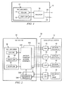
- SS7 link card 12 including in one embodiment a Digital Signal Level 0 (DS-0) link card 14 and an Asynchronous Transfer Mode (ATM) T-1 link card 16 connected to a message transport network 18 such as an Ethernet which can communicate with a data capture system by a Local Area Network (LAN) line 20 or a wireless 22 connection that comprise the number of blocks or modules.
- the link card may also include a Message Transfer Part 2 (MTP-2) link card on channelized or unchannelized T-1 or E-1, a Stream Control Transmission Protocol (SCTP) link card or any of a variety of digital link cards.
- MTP-2 Message Transfer Part 2
- SCTP Stream Control Transmission Protocol
- the SS7 link cards 12 provide parallel processing for an Integrated Link Monitor (ILM).
- the integrated link monitor is used for interactive coupling of the signaling server, SS7 system, to the data capture system for monitoring of SS7 message traffic.
- the transfer of information between the message transport network 18 and the data capture system occurs via at least one of a wireless protocol, a wired protocol and the combination of the wireless protocol and the wired protocol.
- the present invention provides stamping a set of individual Signal Units (SU) with a time offset representing the difference in time between a globally distributed time and a local time the signal unit was written to a refill portion associated with a circular buffer.
- the ILM extracts data from a monitored transmit and receive link. This monitored data must be correlated in time with data from across a global network. Time information is distributed globally throughout the network. This globally distributed time must then be inserted into the monitored data for time correlation of individual monitored signal units across the global network.
- the ILM receives the globally distributed time and fills a globally distributed time stamp of an ILM data packet bundle.
- a host processor and the ILM exchange monitored packets through the circular buffer.
- ILM data packet bundles are assembled in the refill portion of the circular buffer by the ILM and a release portion of the circular buffer is released to the host processor for network transmission.
- the ILM then begins filling the refill portion of the circular buffer in real-time, near real-time, contemporaneously or independently to transmission of the release portion of the circular buffer by the host processor.
- a timer algorithm was developed to track time based on the release and refill operations of the circular buffer.
- a bundle overhead is stamped with the globally distributed time.
- the ILM is informed of the availability of the refill portion of the circular buffer.
- the ILM begins updating the time offset for this refill portion of the circular buffer.
- the time offset is inserted into the bundled data stream along with the monitored signal unit.
- the data capture system can then compute the globally distributed time for each signal unit by adding the time offset for the signal unit to the globally distributed time provided in the bundle overhead.
- the ILM virtually taps the transmit and receive data links to allow alignment of the series of signal units. Aligned signal units are copied to a Direct Memory Access (DMA) control function for assembling ILM data packet bundles in the refill portion of the circular buffer in host memory.
- DMA Direct Memory Access
- a context controlled level 2 state machine extracts the level 2 information and performs level 2 functions such as sequencing and error checking.
- a context of the associated link is loaded based on the availability of an input for the link.
- Inputs consist of a link control from the host processor which acts as a controlling entity and a request to generate transmit data or a request to process receive data. The input is applied to the level 2 state machine which utilizes the current input and the context loaded state to produce the next state and associated outputs.
- the processing is performed real-time or near real-time for the associated input.
- the integrated link monitoring function provides a parallel logic path to copy transmit and receive ILM data packet bundles. Utilizing visibility into the state of the current context, signal unit alignment is maintained for the copied data.
- the direct memory access function collects the copied signal units provided from each context of the level 2 state machine, and generates bundle overhead required to decode and unbundle the data, identify the source of the data, sequence the data from the given source, and time stamp the data for correlation across multiple monitored entities.
- the system adapted to provide time stamp offset in data packet bundling, having the link card module.
- the link card module may comprise a DS-0 link card and the ATM/T1 link card, a message transfer part 2 link card on channelized or unchannelized T-1 or E-1, a stream control transmission protocol link card or any of a variety of digital link cards.
- the link card module having an integrated link monitor adapted to receive the signal unit and the globally distributed time stamp and the timer coupled to the integrated link monitor.
- the timer is adapted to resolve a difference in time between the reception of the signal unit and the globally distributed time stamp.
- the integrated link monitor executes operations in parallel to the host processor.
- the message transport network is adapted to transfer information between the link card module and the data capture system, the transfer of the information occurs via at least one of the wireless protocol, the wired protocol and a combination of the wireless protocol and the wired protocol.
- a management processor is adapted to transfer information between at least one of the message transport network and the data capture system.
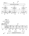
- the SS7 link card 36 is shown, and may include a DS-0 link 38 and an ATM/T-1 link 40 with and an SS7 Internet Protocol (IP) link 42 coupled to the message transport network such as the Ethernet 44a and 44B.
- the link card may include a message transfer part 2 link card on channelized or unchannelized T-1 or E-1, a stream control transmission protocol link card or any of a variety of digital link cards.
- the management processors 54A and 54B are connected to the message transport network 44A and 44B which can communicate with the data capture system 34 via the local area network 52.
- the management processors are responsible for transmitting link status, link configuration and system status to the data capture system 34.
- the blocks in the SS7 system 32 perform the similar functionality to their respective blocks in the SS7 system 10.
- the message transport network 44A and 44B are coupled to management processors 54A and 54B. Globally distributed time is received across the site LAN 52.
- the management processor 54A and 54B synchronize time utilizing the globally distributed time provided by a first server 50.
- the hub 46 is coupled 45 to the message transport network 44A and 44B, the hub 46 is also connected to the network processor 48.
- the SS7 system is shown coupled to the first servers 50, which in turn are coupled to the second server 62 that comprise the number of blocks or modules. These blocks or modules are software, hardware, firmware, and/or the combination of software, hardware, and/or firmware.
- the SS7 system 32 is connected by links 64, 66, 70 and 74 to the message transport network.
- a set of monitoring links 68 and 72 provide virtual taps to extract transmit and receive level 2 information to be received by the data capture system.
- the ILM data packet bundle 84 that comprise the number of blocks or modules is shown. These blocks or modules are software, hardware, firmware, and/or the combination of software, hardware, and/or firmware.
- the ILM data packet bundle 84 is comprised of bundle overhead 88, the globally distributed time stamp 92, the signal unit 96 and a time offset stamp 94.
- the time offset stamp 94 represents the difference in time between the globally distributed time stamped at the beginning of refill of the ILM data packet bundle and the local time that the individual signal unit was written to the ILM data packet bundle.
- the host processor 82 transmits the globally distributed time 90 to annotate the globally distributed time stamp 92 at the beginning of assembly of the ILM data packet bundle.
- the globally distributed time 90 is also referred to as full globally distributed time, and the globally distributed time stamp 92 is also referred to as the globally distributed time stamp.
- the bundle overhead 88 added to the ILM data packet bundle contains level 2 information for sequencing and error checking.
- the monitoring function 86 adds the time offset stamps 94, 98 and 102 based on the time offsets 106, 108 and 110 to the ILM data packet bundle.
- the order of the time offset stamps and the signal units can vary.
- the context of the signal units are written to the bundle overhead.
- ILM data packet bundles release portion 84A and refill portion 84B between the host processor 82 and the monitoring function 86 that comprise the number of blocks or modules will be described. These blocks or modules are software, hardware, firmware, and/or the combination of software, hardware, and/or firmware.
- the host processor 82 fills 1 the globally distributed time stamp A into ILM data packet bundle release portion 84A being assembled in the refill portion 84B of the circular buffer.
- the host processor 82 transfers ownership 2 in real-time, near real-time, contemporaneously or independently to the refill portion of the circular buffer to the monitoring function 86.
- the timer is queried and the ILM begins to fill 3 the refill portion of the circular buffer with received signal units and time offset stamps utilizing the direct memory access control function for copied signal units.
- the ILM resolves the difference in time between the globally distributed time stamp and the local time the signal unit was written to the refill portion of the circular buffer.
- the ILM assigns the time offset for the signal unit.
- the ILM extracts level 2 data associated with the signal unit.
- the release portion of the circular buffer is released 4 to the host processor 82 while the refill portion of the circular buffer is under ownership of the ILM.
- Bundle overhead is assigned by the ILM and includes decoding information, information related to unbundling and source of the signal unit related information.
- the integrated link monitor data packet is bundled including the globally distributed time, the signal unit, time offset and bundle overhead.
- the refill portion of the circular buffer is loaded with the received signal unit, the assigned time offset and the bundle overhead.
- ownership of the release portion of the circular buffer is transferred 5 to the monitoring function 86.
- the releasing of the release portion of the circular buffer to the host processor is in real-time, near real-time, contemporaneously or independently with loading the refill portion of the circular buffer.
- the notification 6 from the monitoring function 86 is received by the host processor 82 to tell the host processor that the refill portion of the circular buffer is full.
- the data from the refill portion of the circular buffer to the data capture system is received 7 from the host processor 72. At this point the refill portion of the circular buffer and the release portion of the circular buffer swap functionality in real-time, near real-time, contemporaneously or independently.
- This system can include multiple circular buffers, integrated link monitors and host processors.
- the state machine 122 is shown coupled to the host processor 82 and coupled 124 to the monitoring function 86. These blocks or modules are software, hardware, firmware, and/or a combination of software, hardware, and/or firmware.
- the virtual tap receives signal units from transmit and receive data links to determine the context of the signal unit aligning the signal unit based upon the state of the current context.
- the context controlled level 2 state machine scans and extracts the level 2 information and performs level 2 functions.
- the state machine tap includes information from message transfer part (MTP-2) and high speed link (HSL) information. Bundle overhead is assigned to the signal unit.
- MTP-2 message transfer part
- HSL high speed link
- the context of the associated link is loaded based on the availability of input for the link.
- Inputs consist of link control from the host processor acting as a controlling entity and requests to generate transmit data or requests to process receive data from the monitoring function 86.
- the input is applied to the level 2 state machine which utilizes the current input and context loaded state to produce the next state and associated outputs.
- the processing is performed real-time or near real-time for the associated input.
- the integrated link monitoring function provides a parallel logic path to copy transmit and receive ILM data packet bundles. Utilizing visibility into the state of the current context, signal unit alignment is maintained for the copied data. Aligned signal units are copied to the direct memory access (DMA) control function for assembling ILM data packet bundles to be stored in host memory.
- DMA direct memory access
- the ILM data packet bundles are assigned bundle overhead for the signal unit.
- FIG. 7 the monitoring function 86 and host processor 82 that comprise a number of blocks or modules are shown in relation to the data stream 132 in accordance with the preferred embodiment of the invention. These blocks or modules are software, hardware, firmware, and/or a combination of software, hardware, and/or firmware.
- the virtual tap 134 of transmit and receive data links allows identification of signal unit source, as an example channel 1 for the monitoring function 86.
- the context of the associated link is loaded based on the availability of the input for the link.
- Inputs consist of link control from the host processor 82 acting as the controlling entity and requests to generate transmit data or requests to process receive data from the monitoring function 86.
- the input is applied to the level 2 state machine which utilizes the current input and context loaded state to produce the next state and associated outputs.
- the processing is performed real-time or near real-time for the associated input.
- the integrated link monitoring function provides a parallel logic path to extract source information for signal unit alignment.
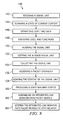
- a method 140 for context controlled data tapping utilizing parallel logic for integrated link monitoring includes receiving 142 the signal unit and indexing 144 to a state of a current context of the signal unit. The determination is performed in parallel to host processing. Level 2 data is extracted 146 from the signal unit and level 2 functions are executed 148. The signal unit is aligned 150 based upon the state of the current context. The aligned signal unit is copied 152 to the direct memory access control function and the signal unit is collected 154 and assigned 156 the bundle overhead associated with the signal unit. The context of the signal unit is loaded 158 based upon the availability of the link input, wherein link inputs are comprised of requests from the controlling entity, requests to generate the transmit signal unit and requests to process the receive signal unit. The state machine produces 160 output based upon the link input and the current context of the state signal. The integrated link monitor data packet bundle is assembled 162 and stored 164 in host memory.
- the capabilities of the invention can be performed fully and/or partially by one or more of the management processor, first server or network processor modules. Also, these capabilities may be performed in the current manner or in a distributed manner and on, or via, any device able to extract level 2 information and perform level 2 functions. Further, although depicted in a particular manner, various blocks may be repositioned without departing from the scope of the current invention.
- the management processor could be integrated within the SS7 link cards. Still further, although depicted in a particular manner, a greater or lesser number of SS7 link cards, management processors, message transport networks, integrated link monitors, hubs, network processors, local area networks or first servers could be utilized.
- integrated link monitor data packet bundles may be utilized with the present invention and such data packet bundles may include complementary information in order to accomplish the present invention, to provide additional features to the present invention, and/or to make the present invention more efficient.
Landscapes
- Engineering & Computer Science (AREA)
- Computer Networks & Wireless Communication (AREA)
- Signal Processing (AREA)
- Data Exchanges In Wide-Area Networks (AREA)
Abstract
Description
- The present invention is generally related to virtually tapping transmit and receive data links utilized for signaling servers and, more specifically to a context controlled data tap utilizing parallel logic for integrated link monitoring.
- Currently, interactively coupling signaling servers to data capture systems requires a multitude of passive taps to monitor
message traffic level 2 information.Level 2 information includes components such as sequencing and error checking. An Integrated Link Monitor (ILM) can provide interactive coupling of the signaling server to a data capture system for monitoring message traffic. The signaling server can be of the Signaling System #7 (SS7) type such as the Alcatel Signaling Server Global (SSG) system. Integrated link monitor coupling of the signal server to the data capture system replaces the multitude of passive taps on each of the signaling server links that were previously used to accomplish this purpose. The information previously received by means of the passive taps is now provided by a series of Ethernet connections. Current integrated link monitoring functions that have been implemented in hardware performs thelevel 2 functions but require the host processor utilization to perform those functions. The use of the host processor to performlevel 2 functions adds significant load to the host processor and reduces its availability to perform distributed application services. - Therefore, what is needed is parallel logic to virtually tap the signaling server message traffic to extract
level 2 information and performlevel 2 functions. More specifically, parallel logic is needed to perform a virtual tap of context-controlled transmit and receive data links to extractlevel 2 information and perform thelevel 2 functions. Thelevel 2 functionality is implemented by means of the integrated link monitor which aligns signal units based on context and copies those signal units to the Direct Memory Access (DMA) function which assembles the integrated link monitor data packet bundles in host memory. - The Integrated Link Monitor (ILM) is used for interactive coupling of the signaling server to the data capture system for monitoring message traffic. The signaling server can be a Signaling System #7 (SS7) system such as the Alcatel Signaling Server Global (SSG). The present invention provides a virtual tap of context-controlled transmit and receive data to extract
level 2 information to send to the data capture system. - The data capture system can be external monitoring equipment such as third party processors.
Level 2 information includes sequencing and error checking information. Virtually tapping transmit and receive data links allowslevel 2 information to be gathered to align Signal Units (SU) based on context. Aligned signal units are copied to a Direct Memory Access (DMA) control function for assembling ILM data packet bundles in host memory. - A context controlled
level 2 state machine extracts thelevel 2 information and performslevel 2 functions. This extraction oflevel 2 information and performance oflevel 2 functions is implemented by means of parallel logic. The context of the transmit and receive data link is loaded based on the availability of an input for the data link. Inputs consist of link control from a controlling entity and requests to generate transmit data or requests to process receive data. The input is applied to thelevel 2 state machine which utilizes the current input and context loaded state to produce the next state and associated outputs. Thelevel 2 processing is performed real-time or near real-time for the input. - The integrated link monitor provides a parallel logic path to copy transmit and receive data. Utilizing visibility into the state of the current context, signal unit alignment is maintained for the copied data. A direct memory access function collects the copied signal units provided from each context of the level-2 state machine, and generates an associated bundle overhead. The bundle overhead includes information necessary to decode and unbundle the data, identify the source of the data, sequence the data from a given source, and time stamp the data for correlation across multiple monitored entities.
- In one embodiment, a method for context controlled data tapping utilizing parallel logic for integrated link monitoring includes receiving a signal unit, indexing to a state associated with a current channel to determine a current context of the signal unit in parallel to host processing and assigning a bundle overhead associated with the signal unit.
- In yet another embodiment, a method for context controlled data tapping utilizing parallel logic for integrated link monitoring including receiving a signal unit, indexing to a state associated with a current channel to determine a current context of the signal unit, the determination being performed in parallel to host processing, extracting
level 2 data from the signal unit, executinglevel 2 functions, aligning the signal unit based upon the state of the current context, copying the aligned signal unit to a direct memory access control function, collecting the signal unit, assigning bundle overhead associated with the signal unit, loading the context of the signal unit based upon the availability of a link input, wherein link inputs are comprised of requests from a controlling entity, wherein link inputs are comprised of requests to generate a transmit signal unit, wherein link inputs are comprised of requests to process a receive signal unit, producing a state machine output based upon the link input and the current context of the state signal, assembling an integrated link monitor data packet bundle, and storing the integrated link monitor data packet bundle in host memory. - In another embodiment, a combined context controlled data tap and parallel logic system for integrated link monitoring including a tap receiving a signal unit, and a state machine coupled to the tap, the state machine adapted to receive a signal unit input and to determine current context of the signal unit, the state machine producing a subsequent state based on the signal unit input and current context of the signal unit.
- In a further embodiment, a computer readable medium including instructions for indexing to a state associated with a current channel to determine a current context of the signal unit, aligning the signal unit based upon the current context, assigning bundle overhead associated with the signal unit, copying the aligned signal unit to a direct memory access control function, and bundling an integrated link monitor data packet in host memory.
-
- Figure 1 depicts an SS7 system in accordance with a preferred embodiment of the present invention;
- Figure 2 depicts an SS7 system coupled to a data capture system in accordance with a preferred embodiment of the present invention;
- Figure 3 depicts an SS7 system coupled to servers in accordance with a preferred embodiment of the present invention;
- Figure 4 depicts an integrated link monitor in accordance with a preferred embodiment of the present invention;
- Figure 5 depicts an integrated link monitor, integrated link monitor data packet bundle and host processor in accordance with a preferred embodiment of the present invention;
- Figure 6 depicts a context controlled data tap utilizing parallel logic for link monitoring in accordance with a preferred embodiment of the present invention;
- Figure 7 depicts an integrated link monitor in accordance with a preferred embodiment of the present invention; and
- Figure 8 depicts a flow chart for processing link monitor data in accordance with a preferred embodiment of the present invention.
- Referring now to FIG. 1, a Signaling System #7 (SS7) 10 is shown, an
SS7 link card 12 including in one embodiment a Digital Signal Level 0 (DS-0)link card 14 and an Asynchronous Transfer Mode (ATM) T-1link card 16 connected to amessage transport network 18 such as an Ethernet which can communicate with a data capture system by a Local Area Network (LAN)line 20 or a wireless 22 connection that comprise the number of blocks or modules. The link card may also include a Message Transfer Part 2 (MTP-2) link card on channelized or unchannelized T-1 or E-1, a Stream Control Transmission Protocol (SCTP) link card or any of a variety of digital link cards. These blocks or modules are software, hardware, firmware, and/or the combination of software, hardware, and/or firmware. The SS7link cards 12 provide parallel processing for an Integrated Link Monitor (ILM). The integrated link monitor is used for interactive coupling of the signaling server, SS7 system, to the data capture system for monitoring of SS7 message traffic. The transfer of information between themessage transport network 18 and the data capture system occurs via at least one of a wireless protocol, a wired protocol and the combination of the wireless protocol and the wired protocol. - The present invention provides stamping a set of individual Signal Units (SU) with a time offset representing the difference in time between a globally distributed time and a local time the signal unit was written to a refill portion associated with a circular buffer. The ILM extracts data from a monitored transmit and receive link. This monitored data must be correlated in time with data from across a global network. Time information is distributed globally throughout the network. This globally distributed time must then be inserted into the monitored data for time correlation of individual monitored signal units across the global network.
- The ILM receives the globally distributed time and fills a globally distributed time stamp of an ILM data packet bundle. A host processor and the ILM exchange monitored packets through the circular buffer. ILM data packet bundles are assembled in the refill portion of the circular buffer by the ILM and a release portion of the circular buffer is released to the host processor for network transmission. The ILM then begins filling the refill portion of the circular buffer in real-time, near real-time, contemporaneously or independently to transmission of the release portion of the circular buffer by the host processor. To resolve the separation of the globally distributed time and a local time tracked by the ILM, a timer algorithm was developed to track time based on the release and refill operations of the circular buffer.
- When the refill portion of the circular buffer is transferred to the ILM, a bundle overhead is stamped with the globally distributed time. In real-time, near real-time, contemporaneously or independently, the ILM is informed of the availability of the refill portion of the circular buffer. The ILM begins updating the time offset for this refill portion of the circular buffer. As each signal unit is appended to the circular buffer, the time offset is inserted into the bundled data stream along with the monitored signal unit. The data capture system can then compute the globally distributed time for each signal unit by adding the time offset for the signal unit to the globally distributed time provided in the bundle overhead.
- The ILM virtually taps the transmit and receive data links to allow alignment of the series of signal units. Aligned signal units are copied to a Direct Memory Access (DMA) control function for assembling ILM data packet bundles in the refill portion of the circular buffer in host memory. A context controlled
level 2 state machine extracts thelevel 2 information and performslevel 2 functions such as sequencing and error checking. A context of the associated link is loaded based on the availability of an input for the link. Inputs consist of a link control from the host processor which acts as a controlling entity and a request to generate transmit data or a request to process receive data. The input is applied to thelevel 2 state machine which utilizes the current input and the context loaded state to produce the next state and associated outputs. The processing is performed real-time or near real-time for the associated input. The integrated link monitoring function provides a parallel logic path to copy transmit and receive ILM data packet bundles. Utilizing visibility into the state of the current context, signal unit alignment is maintained for the copied data. The direct memory access function collects the copied signal units provided from each context of thelevel 2 state machine, and generates bundle overhead required to decode and unbundle the data, identify the source of the data, sequence the data from the given source, and time stamp the data for correlation across multiple monitored entities. - The system adapted to provide time stamp offset in data packet bundling, having the link card module. The link card module may comprise a DS-0 link card and the ATM/T1 link card, a
message transfer part 2 link card on channelized or unchannelized T-1 or E-1, a stream control transmission protocol link card or any of a variety of digital link cards. The link card module having an integrated link monitor adapted to receive the signal unit and the globally distributed time stamp and the timer coupled to the integrated link monitor. The timer is adapted to resolve a difference in time between the reception of the signal unit and the globally distributed time stamp. The integrated link monitor executes operations in parallel to the host processor. The message transport network is adapted to transfer information between the link card module and the data capture system, the transfer of the information occurs via at least one of the wireless protocol, the wired protocol and a combination of the wireless protocol and the wired protocol. A management processor is adapted to transfer information between at least one of the message transport network and the data capture system. - Referring now to FIG. 2, the
SS7 system 32 coupled to thedata capture system 34 that comprise the number of blocks or modules. These blocks or modules are software, hardware, firmware, and/or the combination of software, hardware, and/or firmware. TheSS7 link card 36 is shown, and may include a DS-0link 38 and an ATM/T-1link 40 with and an SS7 Internet Protocol (IP) link 42 coupled to the message transport network such as theEthernet 44a and 44B. The link card may include amessage transfer part 2 link card on channelized or unchannelized T-1 or E-1, a stream control transmission protocol link card or any of a variety of digital link cards. Themanagement processors message transport network data capture system 34 via thelocal area network 52. The management processors are responsible for transmitting link status, link configuration and system status to thedata capture system 34. The blocks in theSS7 system 32 perform the similar functionality to their respective blocks in theSS7 system 10. Themessage transport network management processors site LAN 52. Themanagement processor first server 50. Thehub 46 is coupled 45 to themessage transport network hub 46 is also connected to thenetwork processor 48. - Referring now to FIG. 3, the SS7 system is shown coupled to the
first servers 50, which in turn are coupled to thesecond server 62 that comprise the number of blocks or modules. These blocks or modules are software, hardware, firmware, and/or the combination of software, hardware, and/or firmware. TheSS7 system 32 is connected bylinks monitoring links level 2 information to be received by the data capture system. - Referring now to FIG. 4, the ILM
data packet bundle 84 that comprise the number of blocks or modules is shown. These blocks or modules are software, hardware, firmware, and/or the combination of software, hardware, and/or firmware. The ILMdata packet bundle 84 is comprised of bundle overhead 88, the globally distributedtime stamp 92, thesignal unit 96 and a time offsetstamp 94. The time offsetstamp 94 represents the difference in time between the globally distributed time stamped at the beginning of refill of the ILM data packet bundle and the local time that the individual signal unit was written to the ILM data packet bundle. Thehost processor 82 transmits the globally distributedtime 90 to annotate the globally distributedtime stamp 92 at the beginning of assembly of the ILM data packet bundle. The globally distributedtime 90 is also referred to as full globally distributed time, and the globally distributedtime stamp 92 is also referred to as the globally distributed time stamp. The bundle overhead 88 added to the ILM data packet bundle containslevel 2 information for sequencing and error checking. Themonitoring function 86 adds the time offsetstamps - Referring now to FIG. 5, the transfer of ILM data packet
bundles release portion 84A andrefill portion 84B between thehost processor 82 and themonitoring function 86 that comprise the number of blocks or modules will be described. These blocks or modules are software, hardware, firmware, and/or the combination of software, hardware, and/or firmware. Thehost processor 82fills 1 the globally distributed time stamp A into ILM data packetbundle release portion 84A being assembled in therefill portion 84B of the circular buffer. Thehost processor 82transfers ownership 2 in real-time, near real-time, contemporaneously or independently to the refill portion of the circular buffer to themonitoring function 86. After ownership of the refill portion of the circular buffer is transferred to the monitoring function the timer is queried and the ILM begins to fill 3 the refill portion of the circular buffer with received signal units and time offset stamps utilizing the direct memory access control function for copied signal units. The ILM resolves the difference in time between the globally distributed time stamp and the local time the signal unit was written to the refill portion of the circular buffer. The ILM assigns the time offset for the signal unit. The ILM extractslevel 2 data associated with the signal unit. The release portion of the circular buffer is released 4 to thehost processor 82 while the refill portion of the circular buffer is under ownership of the ILM. Bundle overhead is assigned by the ILM and includes decoding information, information related to unbundling and source of the signal unit related information. The integrated link monitor data packet is bundled including the globally distributed time, the signal unit, time offset and bundle overhead. The refill portion of the circular buffer is loaded with the received signal unit, the assigned time offset and the bundle overhead. After the information in the release portion of the circular buffer is transferred to the host processor, ownership of the release portion of the circular buffer is transferred 5 to themonitoring function 86. The releasing of the release portion of the circular buffer to the host processor is in real-time, near real-time, contemporaneously or independently with loading the refill portion of the circular buffer. Thenotification 6 from themonitoring function 86 is received by thehost processor 82 to tell the host processor that the refill portion of the circular buffer is full. The data from the refill portion of the circular buffer to the data capture system is received 7 from thehost processor 72. At this point the refill portion of the circular buffer and the release portion of the circular buffer swap functionality in real-time, near real-time, contemporaneously or independently. This system can include multiple circular buffers, integrated link monitors and host processors. - Referring now to FIG. 6, the context controlled data tap utilizing parallel logic for link monitoring that comprise a number of blocks or modules is shown. The
state machine 122 is shown coupled to thehost processor 82 and coupled 124 to themonitoring function 86. These blocks or modules are software, hardware, firmware, and/or a combination of software, hardware, and/or firmware. The virtual tap receives signal units from transmit and receive data links to determine the context of the signal unit aligning the signal unit based upon the state of the current context. The context controlledlevel 2 state machine scans and extracts thelevel 2 information and performslevel 2 functions. The state machine tap includes information from message transfer part (MTP-2) and high speed link (HSL) information. Bundle overhead is assigned to the signal unit. The context of the associated link is loaded based on the availability of input for the link. Inputs consist of link control from the host processor acting as a controlling entity and requests to generate transmit data or requests to process receive data from themonitoring function 86. The input is applied to thelevel 2 state machine which utilizes the current input and context loaded state to produce the next state and associated outputs. The processing is performed real-time or near real-time for the associated input. The integrated link monitoring function provides a parallel logic path to copy transmit and receive ILM data packet bundles. Utilizing visibility into the state of the current context, signal unit alignment is maintained for the copied data. Aligned signal units are copied to the direct memory access (DMA) control function for assembling ILM data packet bundles to be stored in host memory. The ILM data packet bundles are assigned bundle overhead for the signal unit.
Referring now to FIG. 7, themonitoring function 86 andhost processor 82 that comprise a number of blocks or modules are shown in relation to thedata stream 132 in accordance with the preferred embodiment of the invention. These blocks or modules are software, hardware, firmware, and/or a combination of software, hardware, and/or firmware. Thevirtual tap 134 of transmit and receive data links allows identification of signal unit source, as anexample channel 1 for themonitoring function 86. The context of the associated link is loaded based on the availability of the input for the link. Inputs consist of link control from thehost processor 82 acting as the controlling entity and requests to generate transmit data or requests to process receive data from themonitoring function 86. The input is applied to thelevel 2 state machine which utilizes the current input and context loaded state to produce the next state and associated outputs. The processing is performed real-time or near real-time for the associated input. The integrated link monitoring function provides a parallel logic path to extract source information for signal unit alignment. - Referring now to FIG. 8, a
method 140 for context controlled data tapping utilizing parallel logic for integrated link monitoring is shown and includes receiving 142 the signal unit andindexing 144 to a state of a current context of the signal unit. The determination is performed in parallel to host processing.Level 2 data is extracted 146 from the signal unit andlevel 2 functions are executed 148. The signal unit is aligned 150 based upon the state of the current context. The aligned signal unit is copied 152 to the direct memory access control function and the signal unit is collected 154 and assigned 156 the bundle overhead associated with the signal unit. The context of the signal unit is loaded 158 based upon the availability of the link input, wherein link inputs are comprised of requests from the controlling entity, requests to generate the transmit signal unit and requests to process the receive signal unit. The state machine produces 160 output based upon the link input and the current context of the state signal. The integrated link monitor data packet bundle is assembled 162 and stored 164 in host memory. - The following features, separately or in any combination, may also constitute advantageous embodiments of the described or claimed invention:
- The claimed and/or described method comprising storing the bundled integrated link monitor data packet in host memory;
- The claimed and/or described method comprising collecting the signal unit;
- The claimed and/or described method comprising aligning the signal unit based upon the state of the current context;
- The claimed and/or described method, wherein the aligned signal unit is copied to a direct memory access control function;
- The claimed and/or described method, wherein link input includes requests from a controlling entity;
- The claimed and/or described method, wherein link input includes requests to generate a transmit signal unit;
- The claimed and/or described method, wherein link input includes requests to process a receive signal unit;
- The claimed and/or described method, wherein the bundle overhead includes decoding information;
- The claimed and/or described method, wherein the bundle overhead includes information related to unbundling;
- The claimed and/or described method, wherein the bundle overhead includes source of the signal unit;
- A system adapted to provide context controlled data tap and parallel logic system for integrated link monitoring of
claim 18 comprising: a link control coupled to the state machine for controlling input of the signal unit, the link control including coupling to a controlling entity, the link control adapted to receive requests to generate transmit integrated link monitor data packet bundles, the link control adapted to receive requests to process receive integrated link monitor data packet bundles. - Although an exemplary embodiment of the system of the present invention has been illustrated in the accompanied drawings and described in the foregoing detailed description, it will be understood that the invention is not limited to the embodiments disclosed, but is capable of numerous rearrangements, modifications, and substitutions without departing from the spirit of the invention as set forth and defined by the following claims. For example, the capabilities of the invention can be performed fully and/or partially by one or more of the management processor, first server or network processor modules. Also, these capabilities may be performed in the current manner or in a distributed manner and on, or via, any device able to extract
level 2 information and performlevel 2 functions. Further, although depicted in a particular manner, various blocks may be repositioned without departing from the scope of the current invention. For example, the management processor could be integrated within the SS7 link cards. Still further, although depicted in a particular manner, a greater or lesser number of SS7 link cards, management processors, message transport networks, integrated link monitors, hubs, network processors, local area networks or first servers could be utilized. - Further, a lesser or greater number of integrated link monitor data packet bundles may be utilized with the present invention and such data packet bundles may include complementary information in order to accomplish the present invention, to provide additional features to the present invention, and/or to make the present invention more efficient.
Claims (10)
- A method for context controlled data tapping utilizing parallel logic for integrated link monitoring, comprising:receiving a signal unit;indexing to a state associated with a current channel to determine a current context in parallel to host processing; andassigning a bundle overhead associated with the signal unit.
- The method of claim 1 comprising bundling a data packet associated with the integrated link monitor with the signal unit information and the bundle overhead.
- The method of claim 1 comprising extracting level 2 information from the signal unit.
- The method of claim 1 comprising loading the context of the signal unit based upon the availability of a link input.
- The method of claim 1 comprising producing a state machine output based upon the link input and the current context of the state signal.
- The method of claim 1, wherein the bundle overhead includes time stamp related information for correlation across multiple monitored entities.
- A method for context controlled data tapping utilizing parallel logic for integrated link monitoring, comprising:receiving a signal unit;indexing to a state associated with a current channel to determine a current context in parallel to host processing;extracting level 2 data from the signal unit;aligning the signal unit based upon the state of the current context;copying the aligned signal unit to a direct memory access control function;collecting the signal unit;assigning a bundle overhead associated with the signal unit;loading the context of the signal unit based upon the availability of a link input, wherein link inputs are comprised of requests from a controlling entity, wherein link inputs are comprised of requests to generate a transmit signal unit, wherein link inputs are comprised of requests to process a receive signal unit;producing a state machine output based upon the link input and the current context of the state signals; assembling an integrated link monitor data packet bundle; andstoring the integrated link monitor data packet bundle in host memory.
- A system adapted to provide context controlled data tap and parallel logic system for integrated link monitoring, comprising:a tap receiving a signal unit; anda state machine coupled to the tap, the state machine adapted to receive the signal unit and to determine a current context of the signal unit, the state machine producing a subsequent state based on the signal unit input and current context of the signal unit.
- A computer readable medium comprising instructions for:indexing to a state associated with a current channel a signal unit to determine a current context state; aligning the signal unit based upon the current context;assigning a bundle overhead associated with the signal unit;copying the aligned signal unit to a direct memory access control function; andbundling an integrated link monitor data packet in host memory.
- A computer readable medium of claim 9, wherein the bundle overhead associated with the signal unit includes decoding information, unbundling information, source of the data and time stamp information for correlation across multiple monitored entities.
Applications Claiming Priority (3)
| Application Number | Priority Date | Filing Date | Title |
|---|---|---|---|
| US67279505P | 2005-04-19 | 2005-04-19 | |
| US67279605P | 2005-04-19 | 2005-04-19 | |
| US11/315,512 US8565095B2 (en) | 2005-04-19 | 2005-12-22 | Context controlled data tap utilizing parallel logic for integrated link monitoring |
Publications (1)
| Publication Number | Publication Date |
|---|---|
| EP1715623A1 true EP1715623A1 (en) | 2006-10-25 |
Family
ID=36143700
Family Applications (1)
| Application Number | Title | Priority Date | Filing Date |
|---|---|---|---|
| EP06005584A Withdrawn EP1715623A1 (en) | 2005-04-19 | 2006-03-18 | Context controlled data tap utilizing parallel logic for integrated link monitoring |
Country Status (2)
| Country | Link |
|---|---|
| US (1) | US8565095B2 (en) |
| EP (1) | EP1715623A1 (en) |
Families Citing this family (14)
| Publication number | Priority date | Publication date | Assignee | Title |
|---|---|---|---|---|
| US8782654B2 (en) | 2004-03-13 | 2014-07-15 | Adaptive Computing Enterprises, Inc. | Co-allocating a reservation spanning different compute resources types |
| US9558042B2 (en) | 2004-03-13 | 2017-01-31 | Iii Holdings 12, Llc | System and method providing object messages in a compute environment |
| US20070266388A1 (en) | 2004-06-18 | 2007-11-15 | Cluster Resources, Inc. | System and method for providing advanced reservations in a compute environment |
| US8176490B1 (en) | 2004-08-20 | 2012-05-08 | Adaptive Computing Enterprises, Inc. | System and method of interfacing a workload manager and scheduler with an identity manager |
| US8271980B2 (en) | 2004-11-08 | 2012-09-18 | Adaptive Computing Enterprises, Inc. | System and method of providing system jobs within a compute environment |
| US8863143B2 (en) | 2006-03-16 | 2014-10-14 | Adaptive Computing Enterprises, Inc. | System and method for managing a hybrid compute environment |
| US8631130B2 (en) | 2005-03-16 | 2014-01-14 | Adaptive Computing Enterprises, Inc. | Reserving resources in an on-demand compute environment from a local compute environment |
| US9231886B2 (en) | 2005-03-16 | 2016-01-05 | Adaptive Computing Enterprises, Inc. | Simple integration of an on-demand compute environment |
| CA2603577A1 (en) | 2005-04-07 | 2006-10-12 | Cluster Resources, Inc. | On-demand access to compute resources |
| TWI260609B (en) * | 2005-11-23 | 2006-08-21 | Benq Corp | Recording method for optical disc |
| US8041773B2 (en) | 2007-09-24 | 2011-10-18 | The Research Foundation Of State University Of New York | Automatic clustering for self-organizing grids |
| US10877695B2 (en) | 2009-10-30 | 2020-12-29 | Iii Holdings 2, Llc | Memcached server functionality in a cluster of data processing nodes |
| US11720290B2 (en) | 2009-10-30 | 2023-08-08 | Iii Holdings 2, Llc | Memcached server functionality in a cluster of data processing nodes |
| US11132277B2 (en) * | 2012-12-28 | 2021-09-28 | Iii Holdings 2, Llc | System and method for continuous low-overhead monitoring of distributed applications running on a cluster of data processing nodes |
Citations (2)
| Publication number | Priority date | Publication date | Assignee | Title |
|---|---|---|---|---|
| EP1257130A2 (en) * | 2001-05-11 | 2002-11-13 | Alcatel | State machine architecture partitionable into control and data planes |
| EP1487160A2 (en) * | 2003-06-14 | 2004-12-15 | Agilent Technologies Inc. | Service usage records for mobile data communications |
Family Cites Families (8)
| Publication number | Priority date | Publication date | Assignee | Title |
|---|---|---|---|---|
| US4726019A (en) * | 1986-02-28 | 1988-02-16 | American Telephone And Telegraph Company, At&T Bell Laboratories | Digital encoder and decoder synchronization in the presence of late arriving packets |
| KR100300846B1 (en) * | 1997-12-30 | 2001-09-03 | 박종섭 | Method for processing level 2 of no.7 in mobile communication exchanger |
| US6775707B1 (en) * | 1999-10-15 | 2004-08-10 | Fisher-Rosemount Systems, Inc. | Deferred acknowledgment communications and alarm management |
| US6717940B1 (en) * | 1999-12-22 | 2004-04-06 | Lucent Technologies Inc. | Message transfer part level three alias point codes |
| US7650158B2 (en) * | 2001-08-21 | 2010-01-19 | Broadcom Corporation | System and method for synchronizing wireless communication devices |
| WO2004015921A1 (en) * | 2002-08-13 | 2004-02-19 | Xyratex Technology Limited | Network monitor and method |
| US7017006B2 (en) * | 2003-04-28 | 2006-03-21 | Texas Instruments Incorporated | System and method to enable efficient communication with a dynamic information storage and retrieval system, or the like |
| US7916649B2 (en) * | 2004-09-30 | 2011-03-29 | Alcatel-Lucent Usa Inc. | Apparatus and method for monitoring and analysis of communication over a wireless network |
-
2005
- 2005-12-22 US US11/315,512 patent/US8565095B2/en active Active
-
2006
- 2006-03-18 EP EP06005584A patent/EP1715623A1/en not_active Withdrawn
Patent Citations (2)
| Publication number | Priority date | Publication date | Assignee | Title |
|---|---|---|---|---|
| EP1257130A2 (en) * | 2001-05-11 | 2002-11-13 | Alcatel | State machine architecture partitionable into control and data planes |
| EP1487160A2 (en) * | 2003-06-14 | 2004-12-15 | Agilent Technologies Inc. | Service usage records for mobile data communications |
Non-Patent Citations (2)
| Title |
|---|
| ALCATEL: "Alcatel 5070 SSG Signalling Server Global (ETSI Version)", ALCATEL TECHNICAL INFORMATION GUIDE, November 2003 (2003-11-01), XP002377653, Retrieved from the Internet <URL:http://www.alcatel.com/doctypes/opgproductbrochure/pdf/5070_SSG_etsi_tig.pdf> [retrieved on 20060420] * |
| ITU-T: "ITU-T Recommendation Q.701 Functional Description of the Message Transfer Part (MTP) of Signalling System No. 7", ITU-T SPECIFICATIONS OF SIGNALLING SYSTEM NO. 7, 21 April 1993 (1993-04-21), XP002377654, Retrieved from the Internet <URL:http://mirror.itu.int/dms/pay/itu-t/rec/q/T-REC-Q.701-199303-I!!PDF-E.pdf> [retrieved on 20060420] * |
Also Published As
| Publication number | Publication date |
|---|---|
| US20060250971A1 (en) | 2006-11-09 |
| US8565095B2 (en) | 2013-10-22 |
Similar Documents
| Publication | Publication Date | Title |
|---|---|---|
| US8565095B2 (en) | Context controlled data tap utilizing parallel logic for integrated link monitoring | |
| US9464917B2 (en) | Method and system of reading utility meter data over a network | |
| CN111083161A (en) | Data transmission processing method and device and Internet of things equipment | |
| CN106357421A (en) | Method and device for transmitting service flow of flexible Ethernet | |
| EP1892929A1 (en) | A method, an apparatus and a system for message transmission | |
| CN102859921A (en) | System and method for achieving accelerated throughput | |
| US6452946B1 (en) | Apparatus and method for improving performance in master and slave communications systems | |
| CN101420770A (en) | Fault connection processing method and system in wireless transmission | |
| CN103368872A (en) | Data packet forwarding system and method | |
| JP2003518874A (en) | data communication | |
| CN105323128A (en) | Method, device and system for connecting front-end device to server | |
| CN112583775B (en) | Method, device and network equipment for processing message | |
| US8228956B2 (en) | Time stamp offset in data packet bundling | |
| US7281052B2 (en) | Data tracing identifiers | |
| US7010614B2 (en) | System for computing cumulative amount of data received by all RDMA to determine when a complete data transfer has arrived at receiving device | |
| US7082119B1 (en) | Full PBX telephony feature preservation across a voice over packet network | |
| CN118140470A (en) | Data communication method, device, equipment and storage medium | |
| CN101227338B (en) | Timestamp Offset in Packet Bundle | |
| CN114338482A (en) | Message statistical method and device | |
| CN119766903B (en) | Communication method and device of power protocol, storage medium and electronic equipment | |
| US8228788B2 (en) | Network connection device and signal processing method in the network connection device | |
| US20070115854A1 (en) | Method for automatically discovering a bus system in a multipoint transport network, multipoint transport network and network node | |
| CN101123539A (en) | Context-Controlled Data Demux Using Parallel Logic for Synthetic Link Monitoring | |
| KR100311314B1 (en) | Communication protocols processor and method | |
| CN116248172A (en) | Data transmission method, device and storage medium based on TCP/IP protocol and CCSDS protocol |
Legal Events
| Date | Code | Title | Description |
|---|---|---|---|
| PUAI | Public reference made under article 153(3) epc to a published international application that has entered the european phase |
Free format text: ORIGINAL CODE: 0009012 |
|
| AK | Designated contracting states |
Kind code of ref document: A1 Designated state(s): AT BE BG CH CY CZ DE DK EE ES FI FR GB GR HU IE IS IT LI LT LU LV MC NL PL PT RO SE SI SK TR |
|
| AX | Request for extension of the european patent |
Extension state: AL BA HR MK YU |
|
| RAP1 | Party data changed (applicant data changed or rights of an application transferred) |
Owner name: ALCATEL LUCENT |
|
| AKX | Designation fees paid | ||
| STAA | Information on the status of an ep patent application or granted ep patent |
Free format text: STATUS: THE APPLICATION IS DEEMED TO BE WITHDRAWN |
|
| 18D | Application deemed to be withdrawn |
Effective date: 20070426 |
|
| REG | Reference to a national code |
Ref country code: DE Ref legal event code: 8566 |