EP1715460A2 - Diagnostic device - Google Patents
Diagnostic device Download PDFInfo
- Publication number
- EP1715460A2 EP1715460A2 EP06251446A EP06251446A EP1715460A2 EP 1715460 A2 EP1715460 A2 EP 1715460A2 EP 06251446 A EP06251446 A EP 06251446A EP 06251446 A EP06251446 A EP 06251446A EP 1715460 A2 EP1715460 A2 EP 1715460A2
- Authority
- EP
- European Patent Office
- Prior art keywords
- diagnostic
- vehicle
- ecu
- message
- diagnostic device
- Prior art date
- Legal status (The legal status is an assumption and is not a legal conclusion. Google has not performed a legal analysis and makes no representation as to the accuracy of the status listed.)
- Withdrawn
Links
Images

Classifications
-
- G—PHYSICS
- G07—CHECKING-DEVICES
- G07C—TIME OR ATTENDANCE REGISTERS; REGISTERING OR INDICATING THE WORKING OF MACHINES; GENERATING RANDOM NUMBERS; VOTING OR LOTTERY APPARATUS; ARRANGEMENTS, SYSTEMS OR APPARATUS FOR CHECKING NOT PROVIDED FOR ELSEWHERE
- G07C5/00—Registering or indicating the working of vehicles
- G07C5/08—Registering or indicating performance data other than driving, working, idle, or waiting time, with or without registering driving, working, idle or waiting time
- G07C5/0808—Diagnosing performance data
Definitions
- the present invention relates to diagnostic devices. It finds particular application in conjunction with diagnostic devices used for vehicles and will be described with particular reference thereto. It will be appreciated, however, that the invention is also amenable to other applications.
- LEDs Light emitting diodes
- ECU electronice control unit
- diagnostic devices are used for indicating faults in electronic systems (e.g., vehicle adaptive braking systems including an antilock braking system (ABS), transmission control systems, engine control systems, etc).
- ABS antilock braking system
- An operator may reset and/or auto-configure the ECU (e.g., via a switch). In this sense, the LEDs are used as a first step in diagnosing a failure in an ABS.
- ABS/automatic traction control (ATC) ECUs have tended to make on-board LEDs non-functional to the user in certain applications (e.g., where LEDs are hidden or difficult to see due to ECU location/orientation).
- ATC ABS/automatic traction control
- manufacturers tend to include on-board LEDs on all ECUs to accommodate the buyers that do utilize the LEDs.
- the cost of on-board LEDs introduces unnecessary burdens on ECU manufacturers and buyers in cases where LEDs are not used by the buyers.
- DCI diagnostic communication interface
- the DCI unit disclosed in the '952 patent communicates with a data bus (e.g., a serial data bus having a J 1587 vehicle diagnostic connector) via a cable. Furthermore, the DCI includes a plurality of LEDs for communicating diagnostic information from the ECU to an operator. However, when used by itself, the DCI of the '952 patent is only capable of interpreting proprietary messages received from the data bus. In order to interpret standard messages received from the ECU over the data bus, the DCI of the '952 patent must communicate with an external processor (e.g., a PC) via a port connector.
- an external processor e.g., a PC
- a diagnostic device in one embodiment, includes a housing, a connector, and a diagnostic ECU.
- the connector is integrated with the housing and is electrically connected to a diagnostic port of a vehicle.
- the diagnostic ECU is integrated with the housing and electrically communicates with the connector.
- the diagnostic ECU receives and interprets a PLC diagnostic message from a vehicle ECU.
- a diagnostic system on a vehicle includes a vehicle ECU associated with a system on the vehicle, a diagnostic port, a communication line, which supports PLC signals for communicating electrical signals between the vehicle ECU and the diagnostic port, and a diagnostic device.
- the diagnostic device includes a housing, a connector, which is integrated with the housing and electrically connected to the diagnostic port, and a diagnostic ECU, which is integrated with the housing and electrically communicates with the connector.
- the diagnostic ECU receives and interprets a PLC diagnostic message from the vehicle ECU.
- a diagnostic adapter in another embodiment, includes a first electrical socket, which electrically communicates with a communication line of a first segment of a heavy vehicle, and a second electrical socket, which is integrally and electrically connected to a diagnostic device.
- An ECU on the first segment of the heavy vehicle transmits a PLC diagnostic message to the diagnostic device via the communication line, the first electrical socket, and the second electrical socket.
- the diagnostic device 10 includes a housing 12 and a communication module 14 (e.g., one or more light emitting diodes (LEDs) and/or a wireless transmitter), which acts as a means for communicating a user message to a user, integrated into the housing 12.
- a communication module 14 e.g., one or more light emitting diodes (LEDs) and/or a wireless transmitter
- a connector 16 and a diagnostic ECU 20, which acts as a means for receiving and interpreting PLC messages, are also integrated with the housing 12.
- the diagnostic ECU 20 electrically communicates with the connector 16 and the communication module 14.
- a diagnostic port 22 on a vehicle 24 (e.g., a heavy vehicle) is illustrated.
- the connector 16 of the diagnostic device 10 electrically communicates with the diagnostic port 22, which in turn communicates with a communication line 26, 26a, 26b (e.g., a J1939 communication line, a J1587 communication line, etc.) of the vehicle 24.
- the communication line 26, 26a, 26b is capable of transmitting PLC messages.
- Various configurations e.g., seven (7) pins, nine (9) pins, etc.
- the configuration of the connector 16 is designed to mate with the configuration of the diagnostic port 22.
- the diagnostic device 10 and diagnostic port 22 are located in a first segment or portion 24a of the vehicle 24 while a vehicle electronic control unit (ECU) 30 is located in a second segment or portion 24b of the vehicle 24.
- the first segment 24a is independent from, but electrically and mechanically connected to, the second segment 24b.
- the first segment 24a is a tractor portion of the vehicle 24 while the second segment 24b is a trailer portion of the vehicle 24.
- the vehicle ECU 30 is used for providing diagnostic information related to the vehicle.
- the vehicle ECU 30 provides diagnostic information of a vehicle system (e.g., an antilock braking system) indicating a status of various components included in the vehicle system and an overall status of the vehicle system (e.g., whether various sensors in the antilock braking system are operational).
- the vehicle ECU 30 generates a PLC diagnostic message.
- the diagnostic message is transmitted in the form of electrical signals from the vehicle ECU 30 to the diagnostic ECU 20 via the communication line 26, 26a, 26b and the diagnostic port 22.
- an adapter 32 is electrically connected between the communication line 26, 26a, 26b of the first and second segments 24a, 24b, respectively, of the vehicle 24.
- the diagnostic ECU 20 interprets the message, which indicates an operating status of the vehicle system.
- the diagnostic ECU 20 determines the user message to be communicated to the user via the communication module 14 as a function of the diagnostic message received from the vehicle ECU 30.
- the user message is displayed via LEDs integrated with the housing 12.
- the user message is transmitted wirelessly (e.g., via radio-frequency signals transmitted via a radio-frequency transmitter) from the communication module 14 to the user.
- a remote device (not shown), which can be easily viewed by the user, receives the user message and displays an appropriate communication to the user as a function of the user message.
- power is supplied to the vehicle ECU 30 from a power source 34 located on the first segment 24a of the vehicle 24.
- electrical power is supplied from the power source 34 to the vehicle ECU 30 via the adapter 32.
- electrical power is supplied from the power source 34 to the diagnostic device 10 (including the diagnostic ECU 20) via the connector 16 and the diagnostic port 22.
- the adapter 32 includes first, second, and third electrical connectors 40, 42, 44, respectively.
- the first and third electrical connectors 40, 44, respectively include pin configurations for mating with electrical sockets 46, 50, respectively, on the second and first segments 24b, 24a of the vehicle 24. Therefore, the first electrical connector 40 is connected to the electrical socket 46 on the second segment 24b of the vehicle 24 for electrically communicating with the communication line 26b in the second segment 24b of the vehicle. Also, the third electrical connector 44 is connected to the electrical socket 50 on the first segment 24a of the vehicle 24 for electrically communicating with the communication line 26a in the first segment 24a of the vehicle.
- the adapter 32 provides a means for electrically connecting the communication line 26, 26a, 26b of the first and second segments 24a, 24b of the vehicle.
- the second electrical connector 42 of the adapter 32 is configured for mating with the connector 16 (see FIGURE 2) of the diagnostic device 10 and, furthermore, electrically connecting the diagnostic device 10 to the communication line 26, 26a, 26b of the vehicle 24. Therefore, although the diagnostic device 10 is illustrated as being integrally connected to the diagnostic port 22 in the first segment 24a of the vehicle, it is to be understood that the diagnostic device 10 may, instead, be integrally and electrically connected to the second electrical socket 42 of the adapter 32 for resulting in equivalent functionality.
- FIGURES 7-9 illustrate respective cross-sectional views of the electrical connectors 40, 42, 44.
- the connectors 40, 44 each include seven (7) pins (as labeled) for mating with the electrical sockets 46, 50.
- the connector 42 includes nine (9) pins for mating with the connector 16. It is to be understood that other pin configurations are also contemplated.
- FIGURE 10 another embodiment of the present invention is illustrated.
- like components are designated by like numerals with a primed (') suffix and new components are designated by new numerals.
- the second segment 24b' of the vehicle is not mechanically or electrically connected to the first segment (not shown) of the vehicle.
- the first electrical connector 40' of the adapter 32' is electrically connected to the second segment 24b' of the vehicle via 46' and the second electrical connector 42' of the adapter 32' is integrally and electrically connected to a diagnostic device 60.
- the third electrical connector 44' of the adapter 32' is electrically connected to an external power source 62 that supplies electrical power to the diagnostic device 60 and the vehicle ECU 30'.
- FIGURE 10 is useful for receiving diagnostic messages from the vehicle ECU 30' when the second segment 24b' of the vehicle is not electrically connected to the power source 34 (see FIGURE 5) in the first segment 24a (see FIGURE 5) of the vehicle.
Landscapes
- Physics & Mathematics (AREA)
- General Physics & Mathematics (AREA)
- Arrangements For Transmission Of Measured Signals (AREA)
- Details Of Connecting Devices For Male And Female Coupling (AREA)
Abstract
Description
- The present invention relates to diagnostic devices. It finds particular application in conjunction with diagnostic devices used for vehicles and will be described with particular reference thereto. It will be appreciated, however, that the invention is also amenable to other applications.
- Light emitting diodes (LEDs) on-board an electronic control unit (ECU) are used to indicate a finite number of faults on diagnostic devices. Such diagnostic devices are used for indicating faults in electronic systems (e.g., vehicle adaptive braking systems including an antilock braking system (ABS), transmission control systems, engine control systems, etc). An operator may reset and/or auto-configure the ECU (e.g., via a switch). In this sense, the LEDs are used as a first step in diagnosing a failure in an ABS. However, recent trends in locating ABS/automatic traction control (ATC) ECUs have tended to make on-board LEDs non-functional to the user in certain applications (e.g., where LEDs are hidden or difficult to see due to ECU location/orientation). In addition, although LEDs are not always used or desired by buyers, manufacturers tend to include on-board LEDs on all ECUs to accommodate the buyers that do utilize the LEDs. The cost of on-board LEDs introduces unnecessary burdens on ECU manufacturers and buyers in cases where LEDs are not used by the buyers.
- For the reasons discussed above, ECUs that do not include diagnostic displays (e.g., on-board LEDs) are becoming more popular. Furthermore, for those customers who desire diagnostic information from the ECU, discrete diagnostic devices have been developed to convey such information to a location remote from the ECU. For example, a diagnostic communication interface (DCI) unit has been disclosed in
US Patent No. 6,114,952 ("the '952 patent"), which is hereby incorporated by reference. - The DCI unit disclosed in the '952 patent communicates with a data bus (e.g., a serial data bus having a J 1587 vehicle diagnostic connector) via a cable. Furthermore, the DCI includes a plurality of LEDs for communicating diagnostic information from the ECU to an operator. However, when used by itself, the DCI of the '952 patent is only capable of interpreting proprietary messages received from the data bus. In order to interpret standard messages received from the ECU over the data bus, the DCI of the '952 patent must communicate with an external processor (e.g., a PC) via a port connector.
- Other current discrete diagnostic devices also communicate with the J1587 vehicle diagnostic connector. However, these devices are not capable of interpreting power line control (PLC) messages without the use of an interface computing device between the discrete diagnostic device and the vehicle ECU. Furthermore, none of the currently available discrete diagnostic devices is capable of directly communicating with a vehicle trailer without the use of an interface computing device between the discrete diagnostic device and the trailer ECU or without an external power source.
- In one embodiment, a diagnostic device includes a housing, a connector, and a diagnostic ECU. The connector is integrated with the housing and is electrically connected to a diagnostic port of a vehicle. The diagnostic ECU is integrated with the housing and electrically communicates with the connector. The diagnostic ECU receives and interprets a PLC diagnostic message from a vehicle ECU.
- In another embodiment, a diagnostic system on a vehicle includes a vehicle ECU associated with a system on the vehicle, a diagnostic port, a communication line, which supports PLC signals for communicating electrical signals between the vehicle ECU and the diagnostic port, and a diagnostic device. The diagnostic device includes a housing, a connector, which is integrated with the housing and electrically connected to the diagnostic port, and a diagnostic ECU, which is integrated with the housing and electrically communicates with the connector. The diagnostic ECU receives and interprets a PLC diagnostic message from the vehicle ECU.
- In another embodiment, a diagnostic adapter includes a first electrical socket, which electrically communicates with a communication line of a first segment of a heavy vehicle, and a second electrical socket, which is integrally and electrically connected to a diagnostic device. An ECU on the first segment of the heavy vehicle transmits a PLC diagnostic message to the diagnostic device via the communication line, the first electrical socket, and the second electrical socket.
- Examples of the present invention will now be described in detail with reference to the accompanying drawings, in which:
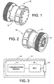
- FIGURE 1 illustrates a first view of a diagnostic device in accordance with one embodiment of the present invention;
- FIGURE 2 illustrates a second view of a diagnostic device in accordance with one embodiment of the present invention;
- FIGURE 3 illustrates a schematic diagram of the diagnostic device;
- FIGURE 4 illustrates a diagnostic port on a vehicle in accordance with one embodiment of the present invention;
- FIGURE 5 illustrates a schematic diagram of the vehicle including the diagnostic device in accordance with one embodiment of the present invention;
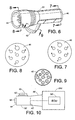
- FIGURE 6 illustrates an adapter in accordance with one embodiment of the present invention;
- FIGURES 7-9 illustrates various cross-sectional views of the adapter; and
- FIGURE 10 illustrates the diagnostic device and adapter in accordance with a second embodiment of the present invention.
- With reference to FIGURES 1-3, a
diagnostic device 10 is illustrated in accordance with one embodiment of the present invention. Thediagnostic device 10 includes ahousing 12 and a communication module 14 (e.g., one or more light emitting diodes (LEDs) and/or a wireless transmitter), which acts as a means for communicating a user message to a user, integrated into thehousing 12. Aconnector 16 and adiagnostic ECU 20, which acts as a means for receiving and interpreting PLC messages, are also integrated with thehousing 12. Thediagnostic ECU 20 electrically communicates with theconnector 16 and thecommunication module 14. - With reference to FIGURES 4 and 5, a
diagnostic port 22 on a vehicle 24 (e.g., a heavy vehicle) is illustrated. Theconnector 16 of thediagnostic device 10 electrically communicates with thediagnostic port 22, which in turn communicates with acommunication line vehicle 24. Thecommunication line connector 16 and thediagnostic port 22. The configuration of theconnector 16 is designed to mate with the configuration of thediagnostic port 22. - The
diagnostic device 10 anddiagnostic port 22 are located in a first segment orportion 24a of thevehicle 24 while a vehicle electronic control unit (ECU) 30 is located in a second segment orportion 24b of thevehicle 24. In one embodiment, thefirst segment 24a is independent from, but electrically and mechanically connected to, thesecond segment 24b. For example, in one embodiment, thefirst segment 24a is a tractor portion of thevehicle 24 while thesecond segment 24b is a trailer portion of thevehicle 24. The vehicle ECU 30 is used for providing diagnostic information related to the vehicle. For example, the vehicle ECU 30 provides diagnostic information of a vehicle system (e.g., an antilock braking system) indicating a status of various components included in the vehicle system and an overall status of the vehicle system (e.g., whether various sensors in the antilock braking system are operational). Thevehicle ECU 30 generates a PLC diagnostic message. The diagnostic message is transmitted in the form of electrical signals from thevehicle ECU 30 to thediagnostic ECU 20 via thecommunication line diagnostic port 22. As will be discussed in more detail below, anadapter 32 is electrically connected between thecommunication line second segments vehicle 24. - Once the
diagnostic ECU 20 receives the diagnostic message from thevehicle ECU 30, thediagnostic ECU 20 interprets the message, which indicates an operating status of the vehicle system. Thediagnostic ECU 20 determines the user message to be communicated to the user via thecommunication module 14 as a function of the diagnostic message received from thevehicle ECU 30. In one embodiment, the user message is displayed via LEDs integrated with thehousing 12. In another embodiment, the user message is transmitted wirelessly (e.g., via radio-frequency signals transmitted via a radio-frequency transmitter) from thecommunication module 14 to the user. In this embodiment, it is contemplated that a remote device (not shown), which can be easily viewed by the user, receives the user message and displays an appropriate communication to the user as a function of the user message. - In the embodiment illustrated in FIGURE 5, power is supplied to the
vehicle ECU 30 from apower source 34 located on thefirst segment 24a of thevehicle 24. In this case, electrical power is supplied from thepower source 34 to thevehicle ECU 30 via theadapter 32. At the same time, electrical power is supplied from thepower source 34 to the diagnostic device 10 (including the diagnostic ECU 20) via theconnector 16 and thediagnostic port 22. - With reference to FIGURES 5-9, the
adapter 32 includes first, second, and thirdelectrical connectors electrical connectors electrical sockets first segments vehicle 24. Therefore, the firstelectrical connector 40 is connected to theelectrical socket 46 on thesecond segment 24b of thevehicle 24 for electrically communicating with thecommunication line 26b in thesecond segment 24b of the vehicle. Also, the thirdelectrical connector 44 is connected to theelectrical socket 50 on thefirst segment 24a of thevehicle 24 for electrically communicating with thecommunication line 26a in thefirst segment 24a of the vehicle. In the illustrated embodiment, theadapter 32 provides a means for electrically connecting thecommunication line second segments - The second
electrical connector 42 of theadapter 32 is configured for mating with the connector 16 (see FIGURE 2) of thediagnostic device 10 and, furthermore, electrically connecting thediagnostic device 10 to thecommunication line vehicle 24. Therefore, although thediagnostic device 10 is illustrated as being integrally connected to thediagnostic port 22 in thefirst segment 24a of the vehicle, it is to be understood that thediagnostic device 10 may, instead, be integrally and electrically connected to the secondelectrical socket 42 of theadapter 32 for resulting in equivalent functionality. - FIGURES 7-9 illustrate respective cross-sectional views of the
electrical connectors connectors electrical sockets connector 42 includes nine (9) pins for mating with theconnector 16. It is to be understood that other pin configurations are also contemplated. - With reference to FIGURE 10, another embodiment of the present invention is illustrated. For ease of understanding this embodiment of the present invention, like components are designated by like numerals with a primed (') suffix and new components are designated by new numerals. In this embodiment, the
second segment 24b' of the vehicle is not mechanically or electrically connected to the first segment (not shown) of the vehicle. The first electrical connector 40' of the adapter 32' is electrically connected to thesecond segment 24b' of the vehicle via 46' and the second electrical connector 42' of the adapter 32' is integrally and electrically connected to adiagnostic device 60. The third electrical connector 44' of the adapter 32' is electrically connected to anexternal power source 62 that supplies electrical power to thediagnostic device 60 and the vehicle ECU 30'. - It is to be understood that the embodiment illustrated in FIGURE 10 is useful for receiving diagnostic messages from the vehicle ECU 30' when the
second segment 24b' of the vehicle is not electrically connected to the power source 34 (see FIGURE 5) in thefirst segment 24a (see FIGURE 5) of the vehicle.
Claims (27)
- A diagnostic device, comprising:a housing;a connector, integrated with the housing, electrically connected to a diagnostic port of a vehicle; anda diagnostic ECU, integrated with the housing and electrically communicating with the connector, receiving and interpreting a power line carrier (PLC) diagnostic message from a vehicle ECU.
- A diagnostic device as set forth in claim 1, further including:a display, integrated with the housing, for displaying a user message as a function of the diagnostic message from the vehicle ECU.
- A diagnostic device according to claim 2, wherein the display includes a light emitting diode.
- A diagnostic device according to any preceding claim, wherein the connector is configured for electrically communicating with at least one of a J 1939 and a J1587 connector on the vehicle.
- A diagnostic device according to any preceding claim, wherein the diagnostic ECU receives the diagnostic message from a trailer portion of the vehicle.
- A diagnostic device according to any preceding claim, wherein the diagnostic ECU receives electrical power via the connector and the diagnostic port.
- A diagnostic device according to any preceding claim, further including:a transmitter, integrated into the housing, for wirelessly transmitting a signal indicative of the diagnostic message.
- A diagnostic system on a vehicle, the system comprising:a vehicle electronic control unit (ECU) associated with a system on the vehicle;a diagnostic port;a communication line, that supports power line carrier (PLC) signals, for communicating electrical signals between the vehicle ECU and the diagnostic port; anda diagnostic device according to any preceding claim.
- A diagnostic system according to claim 8, wherein:the diagnostic device is located in a first portion of the vehicle; andthe vehicle ECU is located in a second, independent portion of the vehicle.
- A diagnostic system according to claim 8 or 9, wherein:the vehicle is a heavy vehicle;the first portion of the vehicle is a tractor portion; andthe second portion of the vehicle is a trailer portion.
- A diagnostic system according to any of claims 8 to 10, wherein the diagnostic message indicates a diagnostic status of an antilock braking system of the trailer.
- A diagnostic system according to any of claims 8 to 11, wherein the system on the vehicle is an antilock braking system.
- A diagnostic system according to any of claims 8 to 12, wherein the diagnostic device further includes:a radio-frequency circuit, integrated into the housing, for transmitting a radio-frequency signal indicative of the diagnostic message.
- A diagnostic system according to any of claims 8 to 13, wherein the diagnostic device is powered by a vehicle power supply that electrically communicates with the diagnostic port.
- A diagnostic system according to any of claims 8 to 14, wherein the vehicle ECU and the communication line are included on a trailer of a heavy vehicle, the diagnostic system further including an adapter having:a first electrical socket electrically connected to a trailer electrical socket, which electrically communicates with the communication line; anda second electrical socket, the diagnostic device being electrically connected to the communication line of the trailer via the first and second electrical sockets of the adapter.
- A diagnostic system according to claim 15, wherein the adapter includes:a third electrical socket electrically connected to an external power source for supplying electrical power to the diagnostic device.
- A diagnostic system according to claim 15, wherein the adapter includes:a third electrical socket electrically connected to a tractor of the heavy vehicle, a vehicle power supply on the tractor powering the diagnostic device via the third electrical socket.
- A diagnostic adapter, comprising:a first electrical socket electrically communicating with a communication line of a first segment of a heavy vehicle; anda second electrical socket integrally and electrically connected to a diagnostic device, an electronic control unit (ECU) on the first segment of the heavy vehicle transmitting a power line carrier (PLC) diagnostic message to the diagnostic device via the communication line, the first electrical socket, and the second electrical socket.
- A diagnostic adapter according to claim 18, further comprising:a third electrical socket electrically connected to an external power source for supplying electrical power to the diagnostic device.
- A diagnostic adapter according to claim 18, further comprising:a third electrical socket electrically connected to a second segment of the heavy vehicle, a power source on the second segment supplying electrical power to the diagnostic device.
- A diagnostic adapter according to claim 20, wherein the first and third electrical sockets include seven pins.
- A method for diagnosing a system on a vehicle, the method comprising:generating a power line carrier (PLC) diagnostic message within a vehicle electronic control unit (ECU);transmitting the diagnostic message from the vehicle ECU to a diagnostic ECU via a communication line;receiving the diagnostic message into the diagnostic ECU; andinterpreting the diagnostic message within the diagnostic ECU.
- A method for diagnosing a system on a vehicle according to claim 22, further including:supplying electrical power to the vehicle and diagnostic ECUs via an external power source electrically connected to the vehicle and diagnostic ECUs via an adapter.
- A method for diagnosing a system on a vehicle according to claim 22 or 23, wherein the diagnostic ECU is located in a first segment of the vehicle and the vehicle ECU is located in a second segment of the vehicle, the method further including:supplying electrical power to the vehicle and diagnostic ECUs via a power source located in the first segment of the vehicle, the electrical power being supplied to the vehicle ECU via an adapter.
- A method for diagnosing a system on a vehicle according to any of claims 22 to 24, further including:displaying a message, as a function of the diagnostic message, on the diagnostic ECU.
- A method for diagnosing a system on a vehicle according to any of claims 22 to 25, further including:wirelessly transmitting a signal, as a function of the diagnostic message, from the diagnostic ECU.
- A diagnostic device, comprising:a housing;a connector, integrated with the housing, electrically connected to a diagnostic port of a vehicle; andmeans for receiving and interpreting a power line carrier (PLC) diagnostic message from a vehicle ECU, the means for receiving and interpreting being integrated with the housing andelectrically communicating with the connector.
Applications Claiming Priority (1)
| Application Number | Priority Date | Filing Date | Title |
|---|---|---|---|
| US11/109,339 US20060235586A1 (en) | 2005-04-19 | 2005-04-19 | Diagnostic device |
Publications (2)
| Publication Number | Publication Date |
|---|---|
| EP1715460A2 true EP1715460A2 (en) | 2006-10-25 |
| EP1715460A3 EP1715460A3 (en) | 2007-08-29 |
Family
ID=36691602
Family Applications (1)
| Application Number | Title | Priority Date | Filing Date |
|---|---|---|---|
| EP06251446A Withdrawn EP1715460A3 (en) | 2005-04-19 | 2006-03-17 | Diagnostic device |
Country Status (2)
| Country | Link |
|---|---|
| US (1) | US20060235586A1 (en) |
| EP (1) | EP1715460A3 (en) |
Cited By (4)
| Publication number | Priority date | Publication date | Assignee | Title |
|---|---|---|---|---|
| FR2915842A1 (en) * | 2007-05-04 | 2008-11-07 | Valeo Electronique Sys Liaison | Data e.g. video film, transmitting method for e.g. on-board computer of hybrid vehicle, involves exchanging data signals between electrical units by carrier currents circulating in corresponding electric power supply networks of units |
| JP2012147120A (en) * | 2011-01-07 | 2012-08-02 | Sumitomo Electric Ind Ltd | Connector device and power line communication apparatus |
| JP2012186626A (en) * | 2011-03-04 | 2012-09-27 | Sumitomo Electric Ind Ltd | Connector device and power line communication device |
| EP3704880A4 (en) * | 2017-10-30 | 2021-08-18 | Cummins Inc. | INTELLIGENT CONNECTOR KIT |
Families Citing this family (12)
| Publication number | Priority date | Publication date | Assignee | Title |
|---|---|---|---|---|
| US20080147268A1 (en) * | 2006-12-14 | 2008-06-19 | Fuller Michael G | Method and apparatus for alternative performance of automobile features |
| US8903597B2 (en) * | 2010-04-30 | 2014-12-02 | Cability, Inc. | Multipurpose in-vehicle diagnostic II adapter |
| US10011213B1 (en) * | 2012-10-23 | 2018-07-03 | Brian Palmer | System for enhanced vehicle performance and efficiency |
| US9563987B2 (en) | 2013-09-30 | 2017-02-07 | Bendix Commercial Vehicle Systems Llc | Vehicle inspection verification and diagnostic unit |
| USD768626S1 (en) * | 2015-03-05 | 2016-10-11 | The Climate Corporation | Data processing device |
| USD783609S1 (en) | 2015-05-07 | 2017-04-11 | The Climate Corporation | Data storage device |
| EP3326312B1 (en) | 2015-07-22 | 2025-10-01 | Arilou Information Security Technologies Ltd. | Vehicle communications bus data security |
| US10084511B2 (en) | 2015-10-15 | 2018-09-25 | Bendix Commercial Vehicle Systems Llc | Apparatus and method for power line communication on a dual voltage vehicle |
| US10818106B2 (en) | 2018-10-15 | 2020-10-27 | Bendix Commercial Vehicle Systems Llc | System and method for pre-trip inspection of a tractor-trailer |
| ES2956846T3 (en) | 2019-03-04 | 2023-12-29 | Climate Llc | Data storage and transfer device for an agricultural intelligence computing system |
| US11394427B2 (en) | 2020-02-27 | 2022-07-19 | Bendix Commercial Vehicle Systems Llc | Interface device interfacing tractor and towed unit networks in a combination vehicle |
| US12545196B2 (en) * | 2024-03-06 | 2026-02-10 | Geotab Inc. | Splitter harness for vehicles with a proprietary interface port connector |
Family Cites Families (45)
| Publication number | Priority date | Publication date | Assignee | Title |
|---|---|---|---|---|
| US4098542A (en) * | 1977-03-16 | 1978-07-04 | The B. F. Goodrich Company | Indicator energizing monitor circuit for anti-skid brake control systems and the like |
| US4837552A (en) * | 1988-03-25 | 1989-06-06 | Allied-Signal Inc. | Non-volatile fault display with magnetic reset switch for adaptive braking system |
| US5181859A (en) * | 1991-04-29 | 1993-01-26 | Trw Inc. | Electrical connector circuit wafer |
| US5327781A (en) * | 1992-07-30 | 1994-07-12 | Allied-Signal Inc. | Method and apparatus for verifying proper wiring of brake pressure modulators |
| US5341298A (en) * | 1992-08-25 | 1994-08-23 | Allied-Signal Inc. | Throttle traction control for automotive vehicle |
| US5541840A (en) * | 1993-06-25 | 1996-07-30 | Chrysler Corporation | Hand held automotive diagnostic service tool |
| US5626479A (en) * | 1993-07-16 | 1997-05-06 | Hughes; Michael T. | Unified connector interface adapter |
| US5554049A (en) * | 1993-08-19 | 1996-09-10 | Woodhead Industries, Inc. | Inline indicating interconnect |
| US20050192727A1 (en) * | 1994-05-09 | 2005-09-01 | Automotive Technologies International Inc. | Sensor Assemblies |
| US5499512A (en) * | 1994-05-09 | 1996-03-19 | Thermo King Corporation | Methods and apparatus for converting a manually operable refrigeration unit to remote operation |
| US5491418A (en) * | 1994-10-27 | 1996-02-13 | General Motors Corporation | Automotive diagnostic communications interface |
| US5632533A (en) * | 1994-11-04 | 1997-05-27 | Itt Corporation | Brake system fault mode generator |
| US5613744A (en) * | 1995-05-24 | 1997-03-25 | Allied Signal, Inc. | Incipient brake fade detection for traction control systems |
| US6043661A (en) * | 1995-09-07 | 2000-03-28 | Gutierrez; Alejandro | School bus and trailer systems tester |
| US6744352B2 (en) * | 1995-11-09 | 2004-06-01 | Vehicle Enhancement Systems, Inc. | System, apparatus and methods for data communication between vehicle and remote data communication terminal, between portions of vehicle and other portions of vehicle, between two or more vehicles, and between vehicle and communications network |
| US6127939A (en) * | 1996-10-14 | 2000-10-03 | Vehicle Enhancement Systems, Inc. | Systems and methods for monitoring and controlling tractor/trailer vehicle systems |
| US5729164A (en) * | 1996-01-11 | 1998-03-17 | Alliedsignal Truck Brake Systems Co. | Solenoid driver interface custom integrated circuit |
| US5739592A (en) * | 1996-01-31 | 1998-04-14 | Grote Industries, Inc. | Power and communications link between a tractor and trailer |
| US5766020A (en) * | 1996-02-12 | 1998-06-16 | Hughes; Michael | Power adapter interface apparatus |
| US6097306A (en) * | 1996-12-03 | 2000-08-01 | E.J. Brooks Company | Programmable lock and security system therefor |
| US5835873A (en) * | 1997-02-21 | 1998-11-10 | Breed Automotive Technology, Inc. | Vehicle safety system with safety device controllers |
| US5920128A (en) * | 1997-02-27 | 1999-07-06 | Grote Industries Inc. | Trailer ABS monitoring and warning system |
| US6025563A (en) * | 1997-10-01 | 2000-02-15 | Vehicle Enhancement Systems, Inc. | Apparatus and method for indicating load weight of a vehicle |
| US6114952A (en) * | 1998-02-27 | 2000-09-05 | Alliedsignal Truck Brake Systems Co. | Diagnostic communication interface unit for an adaptive braking system |
| US6496102B1 (en) * | 1998-11-12 | 2002-12-17 | Meritor Heavy Vehicle Systems, Llc | Passive tag with variable output |
| US6278919B1 (en) * | 1998-12-24 | 2001-08-21 | Yuiltech Co., Ltd. | Apparatus for diagnosing and indicating operational failure in automobiles |
| US6130487A (en) * | 1999-02-19 | 2000-10-10 | Paccar Inc | Electronic interface and method for connecting the electrical systems of a truck and trailer |
| US6256572B1 (en) * | 1999-03-30 | 2001-07-03 | Kelsey-Hayes Company | Remote programming of an ABS electronic control module |
| US6237401B1 (en) * | 1999-04-15 | 2001-05-29 | Alliedsignal Truck Brake Systems Company | Modulator mis-wire test |
| JP3478193B2 (en) * | 1999-05-24 | 2003-12-15 | トヨタ自動車株式会社 | Power monitoring device |
| US6993421B2 (en) * | 1999-07-30 | 2006-01-31 | Oshkosh Truck Corporation | Equipment service vehicle with network-assisted vehicle service and repair |
| US6343844B1 (en) * | 1999-09-13 | 2002-02-05 | Wabash Technology Corporation | Diagnostic mode selector system for anti-lock brake systems and other electronic systems |
| US6380826B1 (en) * | 2000-03-20 | 2002-04-30 | John Mezzalingua Associates, Inc. | Filter assembly |
| US6545593B2 (en) * | 2000-10-13 | 2003-04-08 | R.A. Philips Industries | AC filter for truck tractor cable circuitry |
| US6603394B2 (en) * | 2000-12-08 | 2003-08-05 | Spx Corporation | Multi-protocol wireless communication module |
| US6778888B2 (en) * | 2001-08-24 | 2004-08-17 | Ford Motor Company | Method and system for capturing vehicle data using an RF transmitter |
| US6747552B2 (en) * | 2001-10-23 | 2004-06-08 | Spx Corporation | Apparatus and method for testing an antilock brake system |
| US20030222982A1 (en) * | 2002-03-28 | 2003-12-04 | Hamdan Majil M. | Integrated video/data information system and method for application to commercial vehicles to enhance driver awareness |
| DE10216564B4 (en) * | 2002-04-15 | 2015-12-17 | Wabco Gmbh | Method for data exchange in a vehicle, in which the individual vehicle parts are interconnected via a PLC data bus |
| US6946953B2 (en) * | 2002-05-30 | 2005-09-20 | Vehicle Enhancement Systems, Inc. | Apparatus and method for enhanced data communications and control between a vehicle and a remote data communications terminal |
| US6909956B2 (en) * | 2002-08-14 | 2005-06-21 | Bendix Commercial Vehicle Systems Llc | Method and apparatus for stopping and parking a commercial vehicle |
| US7227455B2 (en) * | 2002-09-10 | 2007-06-05 | Bendix Commercial Vehicle Systems | Mileage information display system |
| US20040083040A1 (en) * | 2002-10-28 | 2004-04-29 | Thomas Parrott | Vehicle data retrieval system |
| US20040090114A1 (en) * | 2002-11-12 | 2004-05-13 | Macnamara Joseph M. | ABS ON-OFF code diagnostics communication system |
| CA2553023C (en) * | 2004-01-09 | 2013-03-19 | United Parcel Service Of America, Inc. | System, method and apparatus for capturing telematics data with an active rfid tag |
-
2005
- 2005-04-19 US US11/109,339 patent/US20060235586A1/en not_active Abandoned
-
2006
- 2006-03-17 EP EP06251446A patent/EP1715460A3/en not_active Withdrawn
Cited By (5)
| Publication number | Priority date | Publication date | Assignee | Title |
|---|---|---|---|---|
| FR2915842A1 (en) * | 2007-05-04 | 2008-11-07 | Valeo Electronique Sys Liaison | Data e.g. video film, transmitting method for e.g. on-board computer of hybrid vehicle, involves exchanging data signals between electrical units by carrier currents circulating in corresponding electric power supply networks of units |
| JP2012147120A (en) * | 2011-01-07 | 2012-08-02 | Sumitomo Electric Ind Ltd | Connector device and power line communication apparatus |
| JP2012186626A (en) * | 2011-03-04 | 2012-09-27 | Sumitomo Electric Ind Ltd | Connector device and power line communication device |
| EP3704880A4 (en) * | 2017-10-30 | 2021-08-18 | Cummins Inc. | INTELLIGENT CONNECTOR KIT |
| US11843205B2 (en) | 2017-10-30 | 2023-12-12 | Cummins Inc. | Smart connector assembly |
Also Published As
| Publication number | Publication date |
|---|---|
| US20060235586A1 (en) | 2006-10-19 |
| EP1715460A3 (en) | 2007-08-29 |
Similar Documents
| Publication | Publication Date | Title |
|---|---|---|
| EP1715460A2 (en) | Diagnostic device | |
| US5739592A (en) | Power and communications link between a tractor and trailer | |
| US6956501B2 (en) | Wireless link for car diagnostics | |
| US8340855B2 (en) | USB isolation for vehicle communication interface | |
| EP2542866B1 (en) | Process variable transmitter with display | |
| EP1186477B1 (en) | Diagnostics, protection and isolation system for electronic devices on a vehicle data communication bus | |
| US6373375B1 (en) | Method for data transmission in a vehicle | |
| US7785151B2 (en) | Connection system, in particular a plug-in connection system for the transmission of data and power supply signals | |
| US8447464B2 (en) | System and method for interfacing between an on-board diagnostic output and a distance measuring instrument input | |
| US20060028327A1 (en) | Wireless replication, verification, and tracking apparatus and methods for towed vehicles | |
| CN102694309B (en) | On-board diagnostic (OBD) system adapter | |
| JP5372056B2 (en) | In-vehicle fault diagnosis system adapter | |
| IL107709A (en) | Tractor-trailer electronic transmission path | |
| US20090316038A1 (en) | Modular camera system | |
| US20120283914A1 (en) | Vehicle steering wheel control system having integrated electronic control unit | |
| CA2718769C (en) | Hardware reconfigurable vehicle on-board diagnostic interface and telematic system | |
| US20050037632A1 (en) | Lighted trailer wiring adapter | |
| US6967830B2 (en) | Expansion module and network for avionic devices | |
| US20050010341A1 (en) | Remote diagnostics device (rdu) | |
| US11289883B1 (en) | Modular plug-and-play power distribution system for a vehicle | |
| US11448679B2 (en) | System and method for testing a tractor trailer | |
| US20200361384A1 (en) | Camera mirror system vehicle integration | |
| US6483444B2 (en) | Multiport communications adapter | |
| KR102141510B1 (en) | Terminal connector of can communication used in car | |
| KR20210054387A (en) | Vehicle Signal Lamp Control Signal Connection Device Using Wireless Communication |
Legal Events
| Date | Code | Title | Description |
|---|---|---|---|
| PUAI | Public reference made under article 153(3) epc to a published international application that has entered the european phase |
Free format text: ORIGINAL CODE: 0009012 |
|
| AK | Designated contracting states |
Kind code of ref document: A2 Designated state(s): AT BE BG CH CY CZ DE DK EE ES FI FR GB GR HU IE IS IT LI LT LU LV MC NL PL PT RO SE SI SK TR |
|
| AX | Request for extension of the european patent |
Extension state: AL BA HR MK YU |
|
| PUAL | Search report despatched |
Free format text: ORIGINAL CODE: 0009013 |
|
| AK | Designated contracting states |
Kind code of ref document: A3 Designated state(s): AT BE BG CH CY CZ DE DK EE ES FI FR GB GR HU IE IS IT LI LT LU LV MC NL PL PT RO SE SI SK TR |
|
| AX | Request for extension of the european patent |
Extension state: AL BA HR MK YU |
|
| AKX | Designation fees paid | ||
| REG | Reference to a national code |
Ref country code: DE Ref legal event code: 8566 |
|
| STAA | Information on the status of an ep patent application or granted ep patent |
Free format text: STATUS: THE APPLICATION IS DEEMED TO BE WITHDRAWN |
|
| 18D | Application deemed to be withdrawn |
Effective date: 20080301 |