EP1715407A2 - Position determination utilizing a cordless device - Google Patents
Position determination utilizing a cordless device Download PDFInfo
- Publication number
- EP1715407A2 EP1715407A2 EP05026879A EP05026879A EP1715407A2 EP 1715407 A2 EP1715407 A2 EP 1715407A2 EP 05026879 A EP05026879 A EP 05026879A EP 05026879 A EP05026879 A EP 05026879A EP 1715407 A2 EP1715407 A2 EP 1715407A2
- Authority
- EP
- European Patent Office
- Prior art keywords
- image data
- retroreflector
- pointing device
- light
- image
- Prior art date
- Legal status (The legal status is an assumption and is not a legal conclusion. Google has not performed a legal analysis and makes no representation as to the accuracy of the status listed.)
- Ceased
Links
Images





Classifications
-
- G—PHYSICS
- G06—COMPUTING OR CALCULATING; COUNTING
- G06F—ELECTRIC DIGITAL DATA PROCESSING
- G06F3/00—Input arrangements for transferring data to be processed into a form capable of being handled by the computer; Output arrangements for transferring data from processing unit to output unit, e.g. interface arrangements
- G06F3/01—Input arrangements or combined input and output arrangements for interaction between user and computer
- G06F3/03—Arrangements for converting the position or the displacement of a member into a coded form
- G06F3/0304—Detection arrangements using opto-electronic means
- G06F3/0312—Detection arrangements using opto-electronic means for tracking the rotation of a spherical or circular member, e.g. optical rotary encoders used in mice or trackballs using a tracking ball or in mouse scroll wheels
-
- G—PHYSICS
- G06—COMPUTING OR CALCULATING; COUNTING
- G06F—ELECTRIC DIGITAL DATA PROCESSING
- G06F3/00—Input arrangements for transferring data to be processed into a form capable of being handled by the computer; Output arrangements for transferring data from processing unit to output unit, e.g. interface arrangements
- G06F3/01—Input arrangements or combined input and output arrangements for interaction between user and computer
- G06F3/03—Arrangements for converting the position or the displacement of a member into a coded form
- G06F3/0304—Detection arrangements using opto-electronic means
- G06F3/0325—Detection arrangements using opto-electronic means using a plurality of light emitters or reflectors or a plurality of detectors forming a reference frame from which to derive the orientation of the object, e.g. by triangulation or on the basis of reference deformation in the picked up image
-
- G—PHYSICS
- G06—COMPUTING OR CALCULATING; COUNTING
- G06F—ELECTRIC DIGITAL DATA PROCESSING
- G06F3/00—Input arrangements for transferring data to be processed into a form capable of being handled by the computer; Output arrangements for transferring data from processing unit to output unit, e.g. interface arrangements
- G06F3/01—Input arrangements or combined input and output arrangements for interaction between user and computer
- G06F3/03—Arrangements for converting the position or the displacement of a member into a coded form
- G06F3/033—Pointing devices displaced or positioned by the user, e.g. mice, trackballs, pens or joysticks; Accessories therefor
- G06F3/0346—Pointing devices displaced or positioned by the user, e.g. mice, trackballs, pens or joysticks; Accessories therefor with detection of the device orientation or free movement in a three-dimensional [3D] space, e.g. 3D mice, 6-DOF [six degrees of freedom] pointers using gyroscopes, accelerometers or tilt-sensors
Definitions
- GUI graphical user interface
- a cordless mouse utilizes a rechargeable or replaceable battery as its power source and radio frequency (RF) signals to communicate position information to the computer. While conventional position tracking systems work well, the electrical cord of a corded mouse can restrict a user's freedom of movement and the power source of a cordless mouse requires constant recharging or replacement.
- a conventional mouse only provides two-dimensional position information. Three-dimensional position information and orientation information are desirable in some position tracking applications.
- a system for generating position information includes a reflector, an image collection system, and a processor.
- the image collection system is configured to collect at least two sets of image data, where one set of image data includes a stronger indication of the reflector than the other set of image data.
- the two sets of image data can be collected in many different ways and may include using a retroreflector as the reflector.
- the two sets of image data are used to generate position information related to the reflector.
- position information related to the reflector is generated by taking the difference between the two set of image data. Because one set of image data includes a stronger indication of the reflector than the other set of image data, the difference between the two sets of image data gives a definitive indication of the reflector's position.
- the two sets of image data nominally cancel each other out at most corresponding data points except the data points which are related to the reflector. Because it is unlikely that the two sets of image data will exactly cancel each other out, a pre-established difference threshold value can be used to identify and separate the insignificant difference values (i.e., the difference values that do not correspond to the reflector) from the significant difference values (i.e., the difference values that do correspond to the reflector).
- the use of a reflector and an image collection system enables two or three dimensional position information to be generated using a passive pointing device that does not require any power. Therefore, the pointing device does not need to be tethered to a computer system or equipped with a battery. The position of the pointing device can be tracked while the pointing device is moved in free space.
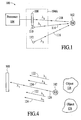
- Fig. 1 depicts a system for generating position information that includes a retroreflector, an image collection system, and a processor.
- Figs. 2 and 3 illustrate the detection angle, the on-axis illumination angle, and the off-axis illumination angle in the image collection system of Fig. 1.
- Fig. 4 depicts light of wavelength ⁇ 1 and wavelength ⁇ 2 that is incident on an imager after reflecting off of a retroreflector and any miscellaneous objects.
- Fig. 5 illustrates the basic operation of the system of Fig. 1.
- Fig. 6 is an exemplary graph of difference image data with the intensity difference values on the x-axis and the number of data points collected at each intensity difference value on the y-axis.
- Fig. 7 depicts an alternative embodiment of the image collection system from Fig. 1 that includes one imager and multiple on-axis and off-axis light sources.
- Fig. 8 depicts an embodiment of an image collection system that includes two imagers and a single light source.
- Fig. 9 depicts an embodiment of the image collection system that includes two imagers and light sources that provide light of two different wavelengths.
- Fig. 10 is a perspective view of the image collection system of Fig. 9 configured in an epipolar geometry.
- Fig. 11 depicts an embodiment of an image collection system that includes on-axis and off-axis light sources and a wavelength-selective filter formed over the retroreflector.
- Fig. 12 depicts an exemplary embodiment of an image collection system in which the light sources of two different wavelengths have the same, or roughly the same, illumination angle and in which a wavelength-selective filter is formed over the retroreflector.
- Fig. 13 depicts an embodiment of an image collection system that includes one imager and a single light source.
- Fig. 14 depicts another embodiment of a single light source image collection system.
- Fig. 15 depicts an embodiment of a system for generating position information that utilizes a reflector other than a retroreflector.
- Figs. 16A and 16B depict an embodiment of a pointing device that incorporates a mechanism for shielding and revealing a retroreflector.
- Figs. 17A and 17B depict another embodiment of a pointing device that incorporates a mechanism for shielding and revealing multiple retroreflectors.
- Figs. 18A and 18B depict an embodiment of a pointing device that includes a retroreflector embedded into a cavity of a pointing device.
- Fig. 19A depicts a top view of an imager that includes a checkerboard filter pattern.
- Fig. 19B depicts a side view of the imager from Fig. 19A with a hybrid filter over the imager.
- Fig. 20 depicts a portable computer configured with an image collection system that includes two light sources and one imager embedded into the housing of the computer.
- Fig. 21 depicts a portable computer configured with an image collection system that includes two light sources and two imagers embedded into the housing of the computer.
- Fig. 22A a front view of an image collection system in which an imager and light sources are incorporated into a free standing housing.
- Fig. 22B depicts a side view of the image collection system of Fig. 22A.
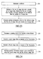
- Fig. 23 depicts a process flow diagram of a method for generating position information.
- Fig. 24 depicts a process flow diagram of another method for generating position information.
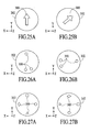
- Figs. 25A and 25B depict an example of a retroreflector that has an orientation-specific shape.
- Figs. 26A and 26B depict an example of multiple retroreflectors configured in an orientation-specific pattern on the surface of a pointing device.
- Figs. 27A and 27B depict an example of multiple retroreflectors that have different shapes.
- Figs. 28A-28C depict an example of a retroreflector that is integrated into a device that has an orientation-specific structural feature.
- Figs. 29A - 29C depict an embodiment of a pointing device that is similar to the pointing device described with reference to Figs. 28A - 28C except that it includes a retroreflector that is not subject to the orientation-specific structural feature of the pointing device.
- Figs. 30A and 30B depict an embodiment of a pointing device in which multiple retroreflectors are used in conjunction with orientation-specific structural features to enable the generation of more detailed orientation information.
- Fig. 31A depicts a side view of the pointing device from Figs. 30A and 30B in which the cavities and retroreflectors are oriented relative to a beam of light such that all of the retroreflectors are illuminated.
- Fig. 31B is a front view of the pointing device from Fig. 31A in which the illumination of all of the retroreflectors is represented by the filled in dark circles.
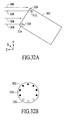
- Fig. 32A depicts a side view of the pointing device from Figs. 30A and 30B in which the cavities and retroreflectors are oriented relative to the beam of light such that only some of the retroreflectors are illuminated.
- Fig. 32B is a front view of the pointing device from Fig. 32A in which the illuminated retroreflectors are represented by filled in dark circles and the non-illuminated retroreflectors are represented by the un-filled in circles.
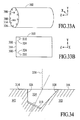
- Figs. 33A and 33B depict an example of a pointing device that utilizes an orientation-specific pattern of retroreflectors as described with reference to Figs. 26A and 26B in conjunction with a pattern of retroreflectors that is integrated into orientation-specific features of the pointing device as described with reference to Figs. 30A - 32B.
- Fig. 34 depicts an embodiment of a cavity in a pointing device and a retroreflector that is attached at the bottom of the cavity.
- Fig. 35 depicts a process flow diagram of a method for generating orientation information.
- Fig. 36 depicts a process flow diagram of a method for generating position information and orientation information.
- a system for generating position information includes a reflector, an image collection system, and a processor.
- the image collection system is configured to collect at least two sets of image data, where one set of image data includes a stronger indication of the reflector than the other set of image data:
- the two sets of image data are used to generate position information related to the reflector.
- position information related to the reflector is generated by taking the difference between the two sets of image data. Because one set of image data includes a stronger indication of the reflector than the other set of image data, the difference between the two sets of image data gives a definitive indication of the reflector's position.
- Fig. 1 depicts a system 100 for generating position information that includes a retroreflector 102, an image collection system 104A, and a processor 106.
- the image collection system includes an imager 108 and first and second light sources 110, 112 that output light 114, 116 having different wavelengths.
- the first light source 110 is located closer to the imager than the second light source 112 and the two light sources and the imager are located in the same plane.
- the first light source is referred to herein as the "on-axis" light source and the second light source is referred to herein as the "off-axis" light source.
- the terms "on-axis” and “off-axis” as used herein are described with reference to Figs. 2 and 3.
- the angle at which light from a light source illuminates the retroreflector 102 is referred to as the illumination angle.
- the illumination angle is measured relative to a plane (as indicated by dashed line 120) that is coplanar with the plane of the major surface of the imager 108.
- the illumination angle of light source 110 is identified as ⁇ i1 and the illumination angle of light source 112 is identified as ⁇ i2 .
- the angle at which light 118 reflected from the retroreflector is incident on the imager is referred to as the detection angle.
- the detection angle is identified as ⁇ d and is measured relative to the same plane as the illumination angle.
- the term "on-axis” applies to the light source or the illuminating beam whose illumination angle has the smaller difference from the detection angle, ⁇ d
- the term “off-axis” refers to the light source or the illumination beam whose illumination angle has the largest difference from the detection angle.
- the relationship of the illumination and detection angles is mathematically expressed as:
- Fig. 3 illustrates changes in the illumination and detection angles that occur as the retroreflector 102 moves relative to the imager 108 and the two light sources 110, 112.
- the difference between the on-axis illumination angle and the detection angle remains smaller than the difference between the off-axis illumination angle and the detection angle,
- the status of a light source as an on-axis light source or an off-axis light source does not change with movement of the retroreflector. It should be noted that this relationship is still maintained when the retroreflector is moved in a direction having a component perpendicular to the plane of the figure.
- the image collection system 104A is used to collect at least two sets of image data.
- the first set of image data is collected in response to light at wavelength ⁇ 1 generated by light source 110 and the second set of image data is collected in response to light of wavelength ⁇ 2 generated by light source 112.
- the first set of image data referred to herein as the on-axis image data, is representative of light of wavelength ⁇ 1 that reflects off the retroreflector 102 and any other objects that are illuminated by light source 110.
- the second set of image data referred to herein as the off-axis image data, is representative of light of wavelength ⁇ 2 that reflects off the retroreflector and any other objects that are illuminated by light source 112.
- the on-axis image data will include a stronger indication of the retroreflector relative to the off-axis image data.
- the intensity of light reflected by the retroreflector to the imager 108 will be much greater at wavelength ⁇ 1 than at wavelength ⁇ 2. Therefore, the intensity values at data points related to the retroreflector will be higher in the on-axis image data than at corresponding data points in the off-axis image data.
- Fig. 4 depicts light 122, 124, 126 of wavelength ⁇ 1 and wavelength ⁇ 2 that is incident on the imager after reflecting off the retroreflector and other objects 128.
- the intensity of light 126 reflected by the retroreflector to the imager will be much greater at wavelength ⁇ 1 than at wavelength ⁇ 2, the intensity of light 122, 124 reflected by the other objects will be roughly the same assuming that the intensity of the light emitted by the two light sources is roughly equal.
- a retroreflector 102 is connected to a pointing device 130 that is held in a hand 132.
- the hand, pointing device, and retroreflector are illuminated by light sources 110 and 112 from Fig. 1.
- On-axis and off-axis image data 136, 138 are collected by the imager while the objects are illuminated by the respective light sources.
- the on-axis image data 136 includes light that reflects off the hand, the pointing device, and the retroreflector.
- the on-axis image data includes a strong indication of light from the retroreflector.
- the strong indication of light is represented in Fig. 5 by a dark spot.
- the off-axis image data 138 also includes light that reflects off the hand, the pointing device, and the retroreflector.
- the intensity of the off-axis light that reflects off the retroreflector towards the imager 108 is small compared to the intensity of the on-axis light that reflects off the retroreflector towards the imager. Therefore, in the off-axis image data, the retroreflector does not appear significantly brighter than any of the other objects.
- the position of the retroreflector can be definitively identified by taking the difference between the two sets of image data to produce a difference image 140. Because most of the data points in the two sets of image data are the same, most of the corresponding data points will cancel each other out, with the one exception being the data points that correspond to the retroreflector. Therefore, the difference between the on-axis image data and off-axis image data gives a definitive indication of the retroreflector's position. As depicted in Fig. 5, the difference image definitively identifies the retroreflector while excluding any of the other objects. Referring back to Fig. 1, the difference operation is carried out by the processor 106.
- light detected by the imager is filtered to limit the detected light to wavelength bands around the wavelengths used for illumination. For example, when light of wavelengths ⁇ 1 and ⁇ 2 is used for illumination, a bulk filter with transmission peaks at wavelengths ⁇ 1 and ⁇ 2 can be located in front of the imager to filter out light of other wavelengths (e.g., ambient light).
- the imager can be configured to distinguish light of the two wavelengths used for illumination. This can be done, for example, by locating a checkerboard filter pattern in front of the imager.
- An example of a hybrid filter for an imager that includes a bulk filter with two peaks and a checkerboard filter pattern is described in U.S. patent applications both entitled “Method and system for wavelength-dependent imaging and detection using a hybrid filter," application serial number 10/739,831, filed on December 18, 2003 and application serial number 10/843,517, filed on May 10, 2004 , both of which are assigned to the assignee of the current invention and incorporated by reference herein.
- Fig. 19A depicts a top view of imager 108 that includes a checkerboard filter pattern. In the embodiment of Fig.
- Fig. 19A depicts a side view of the imager from Fig. 19A with a hybrid filter 115 located in front of the imager.
- the hybrid filter includes a bulk filter 117 and the wavelength-selective filters 111, 113.
- only one set of squares e.g., either the light or dark squares
- the imager can simultaneously generate the two sets of image data while the retroreflector is illuminated by reflected light from both light sources.
- the two sets of image data can be collected sequentially.
- the imager and light sources can be coordinated so a first set of image data is collected while only the first light source is activated and the second set of image data is collected while only the second light source is activated.
- the sequential activation of light sources and collection of the image data can be controlled by the processor. Although one example of sequentially collecting the two sets of image data is described, other sequential collection techniques are possible.
- difference processing includes utilizing a threshold function to eliminate insignificant data points.
- Fig. 6 is an exemplary graph of difference image data with the intensity difference values on the x-axis and the number of data points collected at each intensity difference value on the y-axis. Note that the data points can be corrected to deal with negative intensity difference values. As represented by the peak 144 in the graph, most of the data points are clustered together.
- a threshold difference value is established below which intensity difference values are considered insignificant and above which intensity difference values are considered significant.
- the threshold difference value is established at an intensity between the two clusters of data points 144, 146.
- the threshold difference value is pre-established or set from characteristics of current or prior frames and is used to simplify the difference processing.
- the processor can be configured to discard all intensity difference values that are below the threshold difference value.
- Some artifacts 147 may remain after all the intensity difference values below the threshold difference value are discarded. Discarding insignificant data points reduces the memory requirements of the processor and enables faster processing and less latency. In one embodiment, the image processing time is reduced by processing only portions of an image that are near to where the retroreflector was previously found.
- Intensity difference values that are determined to be significant are processed to identify the retroreflector. For example, all of the significant intensity difference values are processed to identify the center of the retroreflector. The location of the retroreflector's center can then be forwarded to a computer system through, for example, a universal serial bus (USB) interface.
- the processor may perform additional processing including, for example, confirming that the features of the retroreflector in the difference image match the known retroreflector characteristics and confirming that a pattern of potential retroreflector positions in the difference image conforms to a known pattern of positions. For example, the difference image may be compared to known image information to determine if features in the difference image match features of the retroreflector or retroreflectors.
- Fig. 7 depicts an alternative embodiment of the image collection system 104A from Fig. 1 in which the image collection system 104B includes one imager 108, multiple on-axis light sources 110, and multiple off-axis light sources 112.
- light sources 110 generate light at wavelength ⁇ 1 and are located closer to the imager than light sources 112, which generate light at wavelength ⁇ 2.
- the multiple light sources are used to improve the field of illumination of the image collection system over the system of Fig. 1.
- the on-axis and off-axis image data are collected and processed as described above with reference to Fig. 1. Although two examples of light source configurations are described with reference to Figs. 1 and 7, other configurations can be used.
- image collection system 104A Although one exemplary image collection system 104A is described with reference to Fig. 1, many alternative embodiments of the image collection system are possible. All embodiments of the image collection system collect at least two sets of image data, where one set of image data includes a stronger indication of the retroreflector 102 than the other set of image data. As shown below, two sets of image data can be collected in many different ways.
- Fig. 8 depicts an embodiment of an image collection system 104C that includes two imagers 108A, 108B and a single light source 110.
- the single light source provides light at wavelength ⁇ 1 and is located closer to imager 108A than to imager 108B such that the difference between the illumination angle and the detection angel at imager 108A is smaller than the difference between the illumination angle and the detection angle at imager 108B. Because of the location of the light source relative to the two imagers, on-axis image data is collected at imager 108A and off-axis image data is collected at imager 108B. Once the on-axis and off-axis image data is collected, it is processed as described above to generate position information.
- Fig. 9 depicts an alternative embodiment of the image collection system 104D that includes two imagers 108A, 108B and light sources 152, 154 that provide light of two different wavelengths.
- two light sources 152 that generate light at wavelength ⁇ 1 are located nearer to imager 108A than to imager 108B and two light sources 154 that generate light at wavelength ⁇ 2 are located nearer to imager 108B than to imager 108A.
- on-axis image data is collected at imager 108A and off-axis image data is collected at imager 108B.
- on-axis image data is collected at imager 108B and off-axis image data is collected at imager 108A.
- Fig. 9 enables two different sets of on-axis image data and two different sets of off-axis image data to be collected.
- the two imagers and the two different sets of on-axis image data and off-axis image data can be used to generate position information in three dimensions using stereo processing or simplified stereo processing techniques.
- the image collection system is configured in an epipolar geometry relative to the retroreflector.
- Fig. 10 is a perspective view of the image collection system 104D of Fig. 9 configured in an epipolar geometry.
- the x, y, and z coordinates of the retroreflector 102 at position M can be calculated by first determining the positions m1 and m2 of the retroreflector 102 on the imagers 108A, 108B.
- the image collection system includes a wavelength-selective filter associated with the retroreflector.
- the filter may cover the retroreflector.
- Fig. 11 depicts an embodiment of an image collection system 104E that includes on-axis and off-axis light sources 110, 112 and a wavelength-selective filter 158 covering the retroreflector.
- the wavelength-selective filter is transmissive at wavelength ⁇ 1 and blocking at wavelength ⁇ 2. By transmitting light at wavelength ⁇ 1 and blocking light at wavelength ⁇ 2, the wavelength-selective filter provides a higher intensity contrast at the data points corresponding to the retroreflector.
- a wavelength-selective filter associated with the retroreflector can filter one of the wavelengths of light emitted by the light sources, the two sets of image data can be generated with the light sources at the same illumination angle.
- Fig. 12 depicts an exemplary embodiment of an image collection system 104F in which the light sources 110, 112 of two different wavelengths have similar illumination angles.
- the wavelength-specific filter 158 associated with the retroreflector 102 is highly transmissive at wavelength ⁇ 1 and blocking at wavelength ⁇ 2.
- a first set of image data is collected in response to reflected light at wavelength ⁇ 1 and a second set of image data is collected in response to reflected light at wavelength ⁇ 2.
- the first set of image data includes a stronger indication of the retroreflector than the second set of image data.
- the two sets of image data are processed as described above to generate position information.
- the image collection system includes one imager and one light source.
- Fig. 13 depicts an embodiment of an image collection system 104G that includes one imager 108 and one on-axis light source 110.
- the light source generates light at wavelength, ⁇ 1
- the imager is configured with a checkerboard filter, as described above, in which half of the checkerboard squares pass light at wavelength ⁇ 1 and half of the squares block light at wavelength ⁇ 1.
- a first set of image data is generated in response to light at wavelength ⁇ 1 and a second set of image data is generated in response to ambient light minus light at wavelength ⁇ 1. Because the light source is on-axis, the first set of image data includes a stronger indication of the retroreflector than the second set of image data.
- a wavelength-selective filter is located between the retroreflector and the imager.
- the wavelength-selective filter passes light at wavelength ⁇ 1 and blocks light at other wavelengths.
- the wavelength-selective filter provides a higher intensity contrast at the data points corresponding to the retroreflector.
- Fig. 14 depicts another embodiment of a single light source image collection system.
- the image collection system of Fig. 14 utilizes two separate imagers 108A and 108B to collect the two sets of image data: In particular, on-axis image data is collected at imager 108A and off-axis image data is collected at imager 108B.
- a wavelength-selective filter can be located between the retroreflector and the imager to pass light at wavelength ⁇ 1.
- Fig. 15 depicts an embodiment of a system for generating position information that utilizes a mirror 160 instead of a retroreflector.
- the off-axis light 116 is reflected by the mirror at an angle of reflection equal to the angle of incidence. Reflecting the off-axis light at this angle of reflection causes the reflected off-axis light to miss the imager 108.
- the mirror reflects on-axis light 114 back towards the imager, thus enabling the generation of two sets of image data, where one set of image data includes a stronger indication of the reflector than the other set of image data.
- the mirror is oriented such that it reflects one of the two light beams back to the imager.
- the system can be configured such that the mirror reflects light from light source 112 back towards the imager instead of light from light source 110.
- a retroreflector can be used in a pointing application, for example, as a mouse in a GUI-based computer.
- the retroreflector constitutes part of a pointing device that can be held and or moved by a user.
- Figs. 16A and 16B depict an embodiment of a pointing device 170 that incorporates a mechanism for shielding or revealing a retroreflector.
- the pointing device includes a retroreflector 102 (Fig. 16B), a cover 172, guides 174, a finger recess 176, and a return spring 178.
- the retroreflector (not shown) is shielded by the cover. The user can reveal the retroreflector by moving the cover with the movement of a finger engaged with the finger recess 176.
- Fig. 16B shows the cover after it has been moved to reveal the retroreflector.
- Figs. 17A and 17B depict an embodiment of a pointing device 180 that incorporates a mechanism for shielding and revealing multiple retroreflectors.
- the pointing device includes a cover 182, multiple retroreflectors 102, and a linear-to-rotation conversion mechanism 184.
- the linear-to-rotation conversion mechanism includes an axle 186, pivoting joints 188, a slider 173, guides 174, and a finger recess 176.
- the retroreflectors are shielded by the cover.
- a user can reveal the retroreflectors using the linear-to-rotation conversion mechanism to rotate the cover.
- Fig. 17B the cover has been rotated using the linear-to-rotation conversion mechanism to reveal the retroreflectors through holes in the cover.
- the retroreflector is shielded or revealed by a combination of the structure and orientation of the pointing device.
- at least one retroreflector is located at the bottom of a cavity defined in the pointing device such that the retroreflector is shielded from illuminating light by the cavity walls when the pointing device is at some orientations with reference to the illuminating light and is exposed to the illuminating light when the pointing device is at other orientations.
- Figs. 18A and 18B depict an embodiment of a pointing device 190 that includes a retroreflector 102 located at the bottom of a cavity 192 of the pointing device.
- Fig. 18A depicts the pointing device oriented such that the illuminating light 194 is not incident on the retroreflector and Fig. 18B depicts the pointing device oriented such that the illuminating light is incident on the retroreflector.
- some conventional mouse functionality can be achieved by changing some characteristic of the retroreflector or retroreflectors to emulate a mouse function. For example, the shape, size, and/or pattern of a retroreflector or retroreflectors can be changed to emulate a mouse function.
- some functionality can be achieved by gradually revealing or shielding a retroreflector. For example, the scrolling speed can be increased as more of a retroreflector is revealed or decreased as more of the retroreflector is shielded.
- Figs. 20 - 23 depict examples of an image collection system and a pointing device integrated with a computer system.
- Fig. 20 depicts a portable or "laptop" computer 200 configured with an image collection system that includes two light sources 110, 112 and an imager 108 mounted in the housing of the computer.
- the first light source 110 is an on-axis light source that generates light at wavelength ⁇ 1
- the second light source 112 is an off-axis light source that generates light at wavelength ⁇ 2.
- the configuration of the image collection system is similar to that of Fig. 1 with the processor 106 being included within the computer.
- a pointing device 130 that includes a retroreflector 102 is used to indicate position in a GUI-based operating system. Position of the pointing device is determined as described above.
- Fig. 21 depicts a portable computer 200 configured with an image collection system that includes two light sources 152, 154 and two imagers 108A, 108B mounted in the housing of the computer.
- the configuration of the image collection system is similar to that of Fig. 9. Given this configuration, stereo processing can be used to determine the three-dimensional position of the pointing device.
- Figs. 22A and 22B depict front and side views of an embodiment of an image collection system in which an imager 108 and light sources 110 and 112 are incorporated into a free standing housing 202.
- light sources 110 emit light at wavelength ⁇ 1
- light sources 112 emit light at wavelength ⁇ 2.
- the retroreflector is covered with a wavelength-selective filter that is transmissive at wavelength ⁇ 1 and blocking at wavelength ⁇ 2.
- the operation of this configuration is similar to the configuration described above with reference to Fig. 12. Specifically, a first set of image data is collected in response to reflected light at wavelength ⁇ 1 and a second set of image data is collected in response to reflected light at wavelength ⁇ 2.
- the first set of image data includes a stronger indication of the retroreflector than the second set of image data.
- the two sets of image data are processed as described above to generate position information.
- the image collection system depicted in Figs. 22A and 22B can be used in conjunction with a computer.
- the image collection system can be connected to a computer through a wired USB connection or a wireless connection.
- the head 203 of the housing can be rotated to change the field of view of the light sources and imager.
- the head can be rotated downward to, for example, bring a desktop that is used for mouse navigation into view.
- Fig. 23 depicts a process flow diagram of a method for generating position information.
- a reflector is illuminated.
- a first set of image data and a second set of image data are generated.
- the first set of image data includes a stronger indication of the reflector than the second set of image data.
- position information related to the reflector is generated using the first set of image data and the second set of image data.
- Fig. 24 depicts a process flow diagram of another method for generating position information.
- a pointing device that includes a retroreflector is illuminated.
- on-axis image data is generated in response to the illumination.
- off-axis image data is generated in response to the illumination.
- position information related to the retroreflector is generated using the on-axis image data and the off-axis image data.
- the position of the pointing device can be tracked even when the pointing device sits on a non-reflective surface or a microscopically smooth surface such as glass.
- One application includes, for example, tracking the motion of a body part for use in motion capture or game playing.
- Another advantage of the above-described dual image position tracking technique is that the use of a reflector or a retroreflector allows the image data to be collected with reduced exposure time compared to conventional digital photography exposure times.
- the retroreflectors are described as being attached to a pointing device, the retroreflectors could be integrated with some other objects.
- the retroreflectors can be attached to clothing, to parts of the body, or any other object whose position and/or orientation is of interest.
- An object in free space can be characterized in terms of six degrees of freedom, including three degrees of freedom in translation (e.g., the x, y, and z axes) and three degrees of freedom in rotation (e.g., rotation about the x, y, and z axes).
- the position of an object can be characterized in terms of, for example, the x, y, and z axes.
- the orientation of an object can be characterized in terms of, for example, rotation around the x, y, and z axes.
- generating orientation information involves capturing two sets of image data using at least one reflector with an orientation-specific characteristic or a reflector integrated into a device that includes some orientation-specific structural feature. The two sets of image data are then used to generate orientation information.
- the difference is taken between the two sets of image data and because the image data is captured using a reflector with an orientation-specific characteristic or a reflector integrated into a device that includes an orientation-specific structural feature, the resulting difference image includes orientation-specific image information related to the orientation of the reflector.
- Orientation-specific image information can be generated, for example, using a retroreflector with an orientation-specific shape, using multiple retroreflectors in an orientation-specific arrangement, or by locating one or more retroreflectors at the bottom of respective cavities of a pointing device such that the retroreflectors are illuminated only in certain orientations.
- Various examples of techniques for generating orientation-specific image information are described below with reference to Figs. 25A - 36.
- Figs. 25A - 27B depict examples of a retroreflector or multiple retroreflectors that have an orientation-specific characteristic
- FIGS. 28A - 32B depict examples of a retroreflector or retroreflectors integrated into a pointing device that includes some orientation-specific structural feature
- Figs. 33A and 33B depict a pointing device that includes a combination of an orientation-specific pattern of retroreflectors and a pattern of retroreflectors integrated into a pointing device that includes orientation-specific structural features.
- Figs. 25A and 25B depict an example of a retroreflector 300 that has an orientation-specific shape, in this case an arrow. Difference images formed in response to this retroreflector are unique at every orientation of the retroreflector about the z axis. That is, the retroreflector has a rotationally asymmetric shape.
- the arrow points straight up and in Fig. 1B the arrow is rotated approximately forty-five degrees clockwise.
- the image of the arrow is identified by capturing two sets of image data and taking the difference between the two sets of image data.
- the orientation of the retroreflector can be determined by comparing the difference image to known image information.
- the known image information is an image of the arrow in a known orientation.
- the known image and the difference image can be matched to determine orientation.
- the rotation needed to match the difference image to the known image gives an indication of the orientation of the retroreflector.
- the retroreflector is located on the surface of a pointing device 302.
- Figs. 26A and 26B depict an example of multiple retroreflectors having the same shape but configured in an orientation-specific arrangement on the surface of a pointing device 302.
- the pattern includes three retroreflectors with a single retroreflector at the top of the pattern and two retroreflectors nearby each other at the bottom of the pattern. Difference images formed in response to this pattern of retroreflectors are unique at every orientation of the arrangement about the z axis.
- the single retroreflector is at the top of the pattern and the two nearby retroreflectors are at the bottom of the pattern.
- the pattern is rotated about the z axis by about ninety degrees clockwise such that the single retroreflector is at the right of the pattern and the two nearby retroreflectors are at the left of the pattern.
- Figs. 27A and 27B depict an example of multiple retroreflectors 300 that have different shapes in an orientation-specific arrangement.
- the retroreflectors are in the shape of a square, a circle, a triangle, and a diamond. Difference images formed in response to this pattern of retroreflectors are unique in every orientation about the z axis because the different shapes are in different locations in every orientation.
- Figs. 28A - 28C depict an example of a retroreflector 310 that is integrated into a device 302 that has an orientation-specific structural feature.
- the device is a pointing device and the orientation-specific structural feature is a cavity 304 that extends into the pointing device from one of its surfaces.
- the cavity is defined by cavity walls 312 and the retroreflector 310 is located at the bottom of the cavity.
- Fig. 28A depicts a side view of the pointing device that identifies the cavity and the retroreflector located at the bottom of the cavity.
- Fig. 28B depicts a side perspective view of the pointing device, the cavity, and the retroreflector relative to a beam 308 of light.
- Fig. 28B the cavity and retroreflector are oriented relative to the beam of light such that the retroreflector is illuminated by the beam of light. Light that illuminates the retroreflector is reflected back in the same direction it is received. If the orientation of the cavity and the retroreflector relative to the beam of light changes enough, then the beam of light is blocked by some portion of the pointing device such that the retroreflector is not illuminated. In orientations other than that shown in Fig. 28B, the orientation-specific structural feature occludes the retroreflector at least in part.
- Fig. 28C depicts a side perspective view of the pointing device in which the cavity and the retroreflector are oriented relative to the beam of light such that the retroreflector is not illuminated.
- Figs. 28A - 28C Given the configuration of Figs. 28A - 28C, a stronger indication of the retroreflector will be present in the difference image when the cavity and retroreflector are aligned with the beam of light as shown in Fig. 28B than in the difference image that is generated when the cavity and retroreflector are not aligned with the beam of light as shown in Fig. 28C.
- the rotational orientation of the retroreflector and the pointing device about the x and y axes can be characterized based on the existence of the retroreflector in the difference image.
- the alignment of the pointing device is a binary characterization. That is, the pointing device is determined to be either aligned with the beam of light when a strong indication of the retroreflector is present in the difference image or not aligned with the beam of light when a strong indication of the retroreflector is not present in the difference image.
- the orientation between the cavity, the retroreflector, and the beam of light can be determined from the shape of the retroreflector in the difference image or from the intensity values of data points in the difference image that are related to the retroreflector. For example, in one embodiment, a partial image of the retroreflector can be used to determine orientation.
- the intensity of the detected light from the retroreflector can be used to determine orientation.
- the intensity of the detected light from the retroreflector can change as the distance between the retroreflector and the imager changes and/or as orientation-specific structural features reveal or block the retroreflector as the orientation of the pointing device changes. Note that orientation can be determined from the shape of a retroreflector regardless of distance by comparing the ratio of height to width of the image.
- the orientation of the pointing device 302 is determined relative to rotation around the x and y axes.
- the retroreflector 310 disappears from the difference image as the pointing device is tilted to the point where the retroreflector is no longer illuminated.
- the position of the pointing device in Figs. 28A - 28C cannot be tracked using the above-described dual image technique when the retroreflector is not illuminated.
- an additional retroreflector that is not subject to the orientation-specific structural feature of the pointing device is placed on a surface of the pointing device to enable position tracking.
- Figs. 29A - 29C depict an embodiment of a pointing device 302 that is similar to the pointing device described with reference to Figs. 28A - 28C except that it includes a retroreflector 300 that is not subject to the orientation-specific structural feature of the pointing device.
- the additional retroreflector is located on the outer surface 314 of the pointing device.
- both the retroreflector 300 on the outer surface of the pointing device and the retroreflector 310 in the cavity 304 of the pointing device are illuminated by the beam 308 of light. Because both retroreflectors are illuminated, they will both be represented in the difference image.
- the retroreflector 300 on the outer surface of the pointing device is illuminated but the retroreflector 310 in the cavity is not illuminated because the beam of light is blocked by a structural feature of the pointing device. Even though the orientation of the pointing device in Fig.
- 29C prevents the retroreflector 310 within the cavity from being illuminated, the retroreflector 300 on the outer surface of the pointing device is still illuminated and can be used for position tracking.
- the dimensions and wall angles of the cavity can be configured to set the field of view of the retroreflector.
- Figs. 30A and 30B depict an embodiment of a pointing device 302 in which multiple retroreflectors 310 are used in conjunction with orientation-specific structural features 324 to enable the generation of orientation information.
- multiple retroreflectors 310 are located in respective cavities.
- the cavities are arranged in a circle 325.
- Each cavity has its own orientation-specific sensitivity and the orientation of the pointing device can be determined from the locations of the retroreflectors that are represented in the difference image.
- the orientation-specific sensitivity of the cavities is achieved by forming cavity walls 326 and 328 at different angles. As depicted in Fig. 30B, the walls 328 of the cavities closer to the center of the circle are at a larger angle relative to a line perpendicular to the surface 314 of the pointing device than the walls 326 further from the center.
- Fig. 31A depicts a side view of the pointing device 302 from Figs. 30A and 30B in which the cavities 324 and retroreflectors 310 are oriented relative to a beam 308 of light such that all of the retroreflectors are illuminated.
- Fig. 31B is a front view of the pointing device from Fig. 31A in which the illumination of all of the retroreflectors is represented by the filled in dark circles. From the illumination pattern in Fig. 31B, it can be inferred that all of the cavities and retroreflectors are aligned with the beam of light.
- Fig. 32A depicts a side view of the pointing device from Figs.
- Fig. 32B is a front view of the pointing device from Fig. 32A in which the illuminated retroreflectors are represented by filled in dark circles and the non-illuminated retroreflectors are represented by the un-filled in circles.
- the orientation of the pointing device can be determined from the identity of the illuminated retroreflectors.
- a non-illuminated retroreflector indicates that the pointing device is oriented such that the non-illuminated retroreflector has rotated towards the image collection system.
- retroreflectors are located on the pointing device around the perimeter of circle 325, the orientation of the pointing device relative to the x and y axes can be determined.
- retroreflectors may be partially illuminated. Additional orientation information can be obtained from, for example, the shapes and/or intensity values of the image information related to the partially illuminated retroreflectors.
- the orientation-specific structural feature is a slot that extends into a device such as a pointing device.
- a retroreflector is located within the slot. Because of the shape of the slot, the field of view of the retroreflector is larger in one direction than in the other direction. Specifically, the field of view in the direction parallel to the slot is larger than the field of view in the direction perpendicular to the slot. The differences in the field of view allow the retroreflector to be illuminated over a larger range in the parallel direction and a smaller range in the perpendicular direction. A change in orientation in the perpendicular direction will be indicated by the partial or complete disappearance of the retroreflector in the difference image. Characteristics of the field of view of a retroreflector within a slot are a function of the width and depth of the slot. The dimensions and configuration of the orientation-specific structural feature can be set to achieve the desired response.
- FIGs. 33A and 33B depict an example of a pointing device 302 that utilizes an orientation-specific pattern of retroreflectors 300 as described with reference to Figs. 26A and 26B in conjunction with a pattern of retroreflectors 310 that is integrated into orientation-specific features 324 of the pointing device as described with reference to Figs. 30A - 32B.
- the configuration of Figs. 33A and 33B enables the generation of orientation information in terms of rotation around the x, y, and z axes.
- the orientation-specific pattern of retroreflectors 300 on the surface 314 of the pointing device enables the generation of orientation information in terms of rotation around the z axis and the pattern of retroreflectors 310 located in the cavities of the pointing device enables the generation of orientation information in terms of rotation around the x and y axes.
- Fig. 34 depicts an embodiment of a cavity 324 in a pointing device 302 and a retroreflector 310 located at the bottom of the cavity.
- the cavity has at least two walls 326 and 328 that have different angles relative to the axis 330 perpendicular to the surface 314 of the pointing device 302.
- one of the walls 326 of the cavity is at an angle that is near parallel to axis 330 and the other wall 328 of the cavity is at an angle that is non-parallel to axis 330.
- the angles of the walls and the depth of the cavity define the field of view of the retroreflector. Because the angles of the walls are different, the retroreflector has different fields of view at different orientations. The different fields of view are utilized as described above to give an indication of orientation.
- Fig. 34 depicts an example of a cavity, other cavity configurations are possible.
- the cavities depicted in Figs. 30A - 33B are symmetrically oriented about a circle, the cavities could alternatively be located in a different pattern. Additionally, the field of view of the cavities can be in a different, for example, more random configuration.
- Fig. 35 depicts a process flow diagram of a method for generating orientation information.
- a reflector is illuminated.
- a first set of image data and a second set of image data are generated, wherein the first set of image data includes a stronger indication of the reflector than the second set of image data.
- orientation information related to the reflector is generated using the first set of image data and the second set of image data.
- Fig. 36 depicts a process flow diagram of a method for generating position information and orientation information.
- a pointing device that includes a retroreflector is illuminated.
- a first set of image data is generated in response to the illumination.
- a second set of image data is generated in response to the illumination.
- position information and orientation information related to the retroreflector is generated using the first set of image data and the second set of image data.
- orientation-specific shapes and patterns of retroreflectors are described above as examples of orientation-specific characteristics, other orientation-specific configurations are possible.
- retroreflectors in a line, a pattern of retroreflector lines, or the size of retroreflectors can be used to achieve an orientation-specific characteristic.
- orientation-specific structural features are described above, other orientation-specific structural features are possible.
- the retroreflectors are described as being attached to a pointing device, the retroreflectors could be integrated with some other objects.
- the retroreflectors can be attached to clothing, to parts of the body, or any other object whose position and/or orientation is of interest.
Landscapes
- Engineering & Computer Science (AREA)
- General Engineering & Computer Science (AREA)
- Theoretical Computer Science (AREA)
- Human Computer Interaction (AREA)
- Physics & Mathematics (AREA)
- General Physics & Mathematics (AREA)
- Length Measuring Devices By Optical Means (AREA)
- Position Input By Displaying (AREA)
- Radar Systems Or Details Thereof (AREA)
Abstract
Description
- Most position tracking systems used with a graphical user interface (GUI) utilize a mouse to generate two-dimensional position information. The mouse is typically tethered to the computer by an electrical cord through which power is provided from the computer to the mouse and position information is provided from the mouse to the computer. A cordless mouse utilizes a rechargeable or replaceable battery as its power source and radio frequency (RF) signals to communicate position information to the computer. While conventional position tracking systems work well, the electrical cord of a corded mouse can restrict a user's freedom of movement and the power source of a cordless mouse requires constant recharging or replacement.
- In addition to the above-described limitations, a conventional mouse only provides two-dimensional position information. Three-dimensional position information and orientation information are desirable in some position tracking applications.
- A system for generating position information includes a reflector, an image collection system, and a processor. The image collection system is configured to collect at least two sets of image data, where one set of image data includes a stronger indication of the reflector than the other set of image data. The two sets of image data can be collected in many different ways and may include using a retroreflector as the reflector. The two sets of image data are used to generate position information related to the reflector. In particular, position information related to the reflector is generated by taking the difference between the two set of image data. Because one set of image data includes a stronger indication of the reflector than the other set of image data, the difference between the two sets of image data gives a definitive indication of the reflector's position.
- The two sets of image data nominally cancel each other out at most corresponding data points except the data points which are related to the reflector. Because it is unlikely that the two sets of image data will exactly cancel each other out, a pre-established difference threshold value can be used to identify and separate the insignificant difference values (i.e., the difference values that do not correspond to the reflector) from the significant difference values (i.e., the difference values that do correspond to the reflector).
- The use of a reflector and an image collection system enables two or three dimensional position information to be generated using a passive pointing device that does not require any power. Therefore, the pointing device does not need to be tethered to a computer system or equipped with a battery. The position of the pointing device can be tracked while the pointing device is moved in free space.
- Other aspects and advantages of the present invention will become apparent from the following detailed description, taken in conjunction with the accompanying drawings, illustrated by way of example of the principles of the invention.
- Fig. 1 depicts a system for generating position information that includes a retroreflector, an image collection system, and a processor.
- Figs. 2 and 3 illustrate the detection angle, the on-axis illumination angle, and the off-axis illumination angle in the image collection system of Fig. 1.
- Fig. 4 depicts light of wavelength λ1 and wavelength λ2 that is incident on an imager after reflecting off of a retroreflector and any miscellaneous objects.
- Fig. 5 illustrates the basic operation of the system of Fig. 1.
- Fig. 6 is an exemplary graph of difference image data with the intensity difference values on the x-axis and the number of data points collected at each intensity difference value on the y-axis.
- Fig. 7 depicts an alternative embodiment of the image collection system from Fig. 1 that includes one imager and multiple on-axis and off-axis light sources.
- Fig. 8 depicts an embodiment of an image collection system that includes two imagers and a single light source.
- Fig. 9 depicts an embodiment of the image collection system that includes two imagers and light sources that provide light of two different wavelengths.
- Fig. 10 is a perspective view of the image collection system of Fig. 9 configured in an epipolar geometry.
- Fig. 11 depicts an embodiment of an image collection system that includes on-axis and off-axis light sources and a wavelength-selective filter formed over the retroreflector.
- Fig. 12 depicts an exemplary embodiment of an image collection system in which the light sources of two different wavelengths have the same, or roughly the same, illumination angle and in which a wavelength-selective filter is formed over the retroreflector.
- Fig. 13 depicts an embodiment of an image collection system that includes one imager and a single light source.
- Fig. 14 depicts another embodiment of a single light source image collection system.
- Fig. 15 depicts an embodiment of a system for generating position information that utilizes a reflector other than a retroreflector.
- Figs. 16A and 16B depict an embodiment of a pointing device that incorporates a mechanism for shielding and revealing a retroreflector.
- Figs. 17A and 17B depict another embodiment of a pointing device that incorporates a mechanism for shielding and revealing multiple retroreflectors.
- Figs. 18A and 18B depict an embodiment of a pointing device that includes a retroreflector embedded into a cavity of a pointing device.
- Fig. 19A depicts a top view of an imager that includes a checkerboard filter pattern.
- Fig. 19B depicts a side view of the imager from Fig. 19A with a hybrid filter over the imager.
- Fig. 20 depicts a portable computer configured with an image collection system that includes two light sources and one imager embedded into the housing of the computer.
- Fig. 21 depicts a portable computer configured with an image collection system that includes two light sources and two imagers embedded into the housing of the computer.
- Fig. 22A a front view of an image collection system in which an imager and light sources are incorporated into a free standing housing.
- Fig. 22B depicts a side view of the image collection system of Fig. 22A.
- Fig. 23 depicts a process flow diagram of a method for generating position information.
- Fig. 24 depicts a process flow diagram of another method for generating position information.
- Figs. 25A and 25B depict an example of a retroreflector that has an orientation-specific shape.
- Figs. 26A and 26B depict an example of multiple retroreflectors configured in an orientation-specific pattern on the surface of a pointing device.
- Figs. 27A and 27B depict an example of multiple retroreflectors that have different shapes.
- Figs. 28A-28C depict an example of a retroreflector that is integrated into a device that has an orientation-specific structural feature.
- Figs. 29A - 29C depict an embodiment of a pointing device that is similar to the pointing device described with reference to Figs. 28A - 28C except that it includes a retroreflector that is not subject to the orientation-specific structural feature of the pointing device.
- Figs. 30A and 30B depict an embodiment of a pointing device in which multiple retroreflectors are used in conjunction with orientation-specific structural features to enable the generation of more detailed orientation information.
- Fig. 31A depicts a side view of the pointing device from Figs. 30A and 30B in which the cavities and retroreflectors are oriented relative to a beam of light such that all of the retroreflectors are illuminated.
- Fig. 31B is a front view of the pointing device from Fig. 31A in which the illumination of all of the retroreflectors is represented by the filled in dark circles.
- Fig. 32A depicts a side view of the pointing device from Figs. 30A and 30B in which the cavities and retroreflectors are oriented relative to the beam of light such that only some of the retroreflectors are illuminated.
- Fig. 32B is a front view of the pointing device from Fig. 32A in which the illuminated retroreflectors are represented by filled in dark circles and the non-illuminated retroreflectors are represented by the un-filled in circles.
- Figs. 33A and 33B depict an example of a pointing device that utilizes an orientation-specific pattern of retroreflectors as described with reference to Figs. 26A and 26B in conjunction with a pattern of retroreflectors that is integrated into orientation-specific features of the pointing device as described with reference to Figs. 30A - 32B.
- Fig. 34 depicts an embodiment of a cavity in a pointing device and a retroreflector that is attached at the bottom of the cavity.
- Fig. 35 depicts a process flow diagram of a method for generating orientation information.
- Fig. 36 depicts a process flow diagram of a method for generating position information and orientation information.
- Throughout the description similar reference numbers may be used to identify similar elements.
- A system for generating position information includes a reflector, an image collection system, and a processor. The image collection system is configured to collect at least two sets of image data, where one set of image data includes a stronger indication of the reflector than the other set of image data: The two sets of image data are used to generate position information related to the reflector. In particular, position information related to the reflector is generated by taking the difference between the two sets of image data. Because one set of image data includes a stronger indication of the reflector than the other set of image data, the difference between the two sets of image data gives a definitive indication of the reflector's position.
- Fig. 1 depicts a
system 100 for generating position information that includes aretroreflector 102, animage collection system 104A, and aprocessor 106. In the embodiment of Fig. 1, the image collection system includes animager 108 and first and secondlight sources output light light source 110 is located closer to the imager than the secondlight source 112 and the two light sources and the imager are located in the same plane. The first light source is referred to herein as the "on-axis" light source and the second light source is referred to herein as the "off-axis" light source. - The terms "on-axis" and "off-axis" as used herein are described with reference to Figs. 2 and 3. The angle at which light from a light source illuminates the
retroreflector 102 is referred to as the illumination angle. Referring to Fig. 2, the illumination angle is measured relative to a plane (as indicated by dashed line 120) that is coplanar with the plane of the major surface of theimager 108. The illumination angle oflight source 110 is identified as θi1 and the illumination angle oflight source 112 is identified as θi2. The angle at which light 118 reflected from the retroreflector is incident on the imager is referred to as the detection angle. The detection angle is identified as θd and is measured relative to the same plane as the illumination angle. In the case of two illumination angles, θi1 and θi2, the term "on-axis" applies to the light source or the illuminating beam whose illumination angle has the smaller difference from the detection angle, θd, and the term "off-axis" refers to the light source or the illumination beam whose illumination angle has the largest difference from the detection angle. Referring to Fig. 2, the relationship of the illumination and detection angles is mathematically expressed as: |θi1 - θd| < |θi2 - θd|. - Fig. 3 illustrates changes in the illumination and detection angles that occur as the
retroreflector 102 moves relative to theimager 108 and the twolight sources - Referring back to Fig. 1, the
image collection system 104A is used to collect at least two sets of image data. The first set of image data is collected in response to light at wavelength λ1 generated bylight source 110 and the second set of image data is collected in response to light of wavelength λ2 generated bylight source 112. The first set of image data, referred to herein as the on-axis image data, is representative of light of wavelength λ1 that reflects off theretroreflector 102 and any other objects that are illuminated bylight source 110. The second set of image data, referred to herein as the off-axis image data, is representative of light of wavelength λ2 that reflects off the retroreflector and any other objects that are illuminated bylight source 112. Because the on-axis illumination angle is closer to the detection angle than the off-axis illumination angle, the on-axis image data will include a stronger indication of the retroreflector relative to the off-axis image data. In this case, the intensity of light reflected by the retroreflector to theimager 108 will be much greater at wavelength λ1 than at wavelength λ2. Therefore, the intensity values at data points related to the retroreflector will be higher in the on-axis image data than at corresponding data points in the off-axis image data. Fig. 4 depicts light 122, 124, 126 of wavelength λ1 and wavelength λ2 that is incident on the imager after reflecting off the retroreflector andother objects 128. While the intensity oflight 126 reflected by the retroreflector to the imager will be much greater at wavelength λ1 than at wavelength λ2, the intensity oflight - The difference in the intensities of light that is reflected from the
retroreflector 102 at the two wavelengths is used to generate position information. The basic operation of the system of Fig. 1 is described with reference to Fig. 5. In Fig. 5, aretroreflector 102 is connected to apointing device 130 that is held in ahand 132. The hand, pointing device, and retroreflector are illuminated bylight sources axis image data axis image data 136 includes light that reflects off the hand, the pointing device, and the retroreflector. Because the illumination angle at wavelength λ1 and the detection angle are similar, the on-axis image data includes a strong indication of light from the retroreflector. The strong indication of light is represented in Fig. 5 by a dark spot. The off-axis image data 138 also includes light that reflects off the hand, the pointing device, and the retroreflector. However, because the off-axis image data is obtained in response to off-axis light, the intensity of the off-axis light that reflects off the retroreflector towards theimager 108 is small compared to the intensity of the on-axis light that reflects off the retroreflector towards the imager. Therefore, in the off-axis image data, the retroreflector does not appear significantly brighter than any of the other objects. - In comparing the on-
axis image data 136 to the off-axis image data 138, the only significant difference between the two data sets (assuming the data sets are captured simultaneously or nearly simultaneously) is the indication of theretroreflector 102. In view of this, the position of the retroreflector can be definitively identified by taking the difference between the two sets of image data to produce adifference image 140. Because most of the data points in the two sets of image data are the same, most of the corresponding data points will cancel each other out, with the one exception being the data points that correspond to the retroreflector. Therefore, the difference between the on-axis image data and off-axis image data gives a definitive indication of the retroreflector's position. As depicted in Fig. 5, the difference image definitively identifies the retroreflector while excluding any of the other objects. Referring back to Fig. 1, the difference operation is carried out by theprocessor 106. - Because a difference function is relied upon to generate position information, it is important to generate two sets of image data that can be efficiently compared. In one embodiment, light detected by the imager is filtered to limit the detected light to wavelength bands around the wavelengths used for illumination. For example, when light of wavelengths λ1 and λ2 is used for illumination, a bulk filter with transmission peaks at wavelengths λ1 and λ2 can be located in front of the imager to filter out light of other wavelengths (e.g., ambient light).
- The imager can be configured to distinguish light of the two wavelengths used for illumination. This can be done, for example, by locating a checkerboard filter pattern in front of the imager. An example of a hybrid filter for an imager that includes a bulk filter with two peaks and a checkerboard filter pattern is described in U.S. patent applications both entitled "Method and system for wavelength-dependent imaging and detection using a hybrid filter," application serial number
10/739,831, filed on December 18, 2003 10/843,517, filed on May 10, 2004 imager 108 that includes a checkerboard filter pattern. In the embodiment of Fig. 19A, some imager pixels are covered by filters 111 (represented by the light squares) that pass light at wavelength λ1 and the other imager pixels are covered by filters 113 (represented by the dark squares) that pass light at wavelength λ2. Fig. 19B depicts a side view of the imager from Fig. 19A with ahybrid filter 115 located in front of the imager. The hybrid filter includes abulk filter 117 and the wavelength-selective filters - Alternatively, the two sets of image data can be collected sequentially. For example, the imager and light sources can be coordinated so a first set of image data is collected while only the first light source is activated and the second set of image data is collected while only the second light source is activated. The sequential activation of light sources and collection of the image data can be controlled by the processor. Although one example of sequentially collecting the two sets of image data is described, other sequential collection techniques are possible.
- Although the two sets of image data essentially cancel each other out in all areas except at the retroreflector, there are usually small differences in light intensity at the non-retroreflector data points. These intensity differences are insignificant in comparison to the intensity differences at the data points that correspond to the retroreflector. In an embodiment, difference processing includes utilizing a threshold function to eliminate insignificant data points. Fig. 6 is an exemplary graph of difference image data with the intensity difference values on the x-axis and the number of data points collected at each intensity difference value on the y-axis. Note that the data points can be corrected to deal with negative intensity difference values. As represented by the
peak 144 in the graph, most of the data points are clustered together. These data points represent the areas where the two sets of image data are roughly equivalent and essentially, but not completely, cancel each other out. There is another smaller cluster ofdata points 146 located where the intensity difference values are greater. This smaller cluster of data points corresponds to the light that is reflected from the retroreflector. As described above, the intensity difference values at these data points are larger because of the on-axis versus off-axis effect. - In order to easily separate the insignificant intensity difference values (i.e., the difference values that do not correspond to the retroreflector) from the significant intensity difference values (i.e., the difference values that do correspond to the retroreflector), a threshold difference value is established below which intensity difference values are considered insignificant and above which intensity difference values are considered significant. As represented by the dashed
line 148 in Fig. 6, the threshold difference value is established at an intensity between the two clusters ofdata points artifacts 147 may remain after all the intensity difference values below the threshold difference value are discarded. Discarding insignificant data points reduces the memory requirements of the processor and enables faster processing and less latency. In one embodiment, the image processing time is reduced by processing only portions of an image that are near to where the retroreflector was previously found. - Intensity difference values that are determined to be significant are processed to identify the retroreflector. For example, all of the significant intensity difference values are processed to identify the center of the retroreflector. The location of the retroreflector's center can then be forwarded to a computer system through, for example, a universal serial bus (USB) interface. The processor may perform additional processing including, for example, confirming that the features of the retroreflector in the difference image match the known retroreflector characteristics and confirming that a pattern of potential retroreflector positions in the difference image conforms to a known pattern of positions. For example, the difference image may be compared to known image information to determine if features in the difference image match features of the retroreflector or retroreflectors.
- Characteristics of the lighting can be established to provide good image data. Fig. 7 depicts an alternative embodiment of the
image collection system 104A from Fig. 1 in which theimage collection system 104B includes oneimager 108, multiple on-axis light sources 110, and multiple off-axis light sources 112. In this embodiment,light sources 110 generate light at wavelength λ1 and are located closer to the imager thanlight sources 112, which generate light at wavelength λ2. The multiple light sources are used to improve the field of illumination of the image collection system over the system of Fig. 1. The on-axis and off-axis image data are collected and processed as described above with reference to Fig. 1. Although two examples of light source configurations are described with reference to Figs. 1 and 7, other configurations can be used. - Although one exemplary
image collection system 104A is described with reference to Fig. 1, many alternative embodiments of the image collection system are possible. All embodiments of the image collection system collect at least two sets of image data, where one set of image data includes a stronger indication of theretroreflector 102 than the other set of image data. As shown below, two sets of image data can be collected in many different ways. - Fig. 8 depicts an embodiment of an
image collection system 104C that includes twoimagers light source 110. The single light source provides light at wavelength λ1 and is located closer toimager 108A than toimager 108B such that the difference between the illumination angle and the detection angel atimager 108A is smaller than the difference between the illumination angle and the detection angle atimager 108B. Because of the location of the light source relative to the two imagers, on-axis image data is collected atimager 108A and off-axis image data is collected atimager 108B. Once the on-axis and off-axis image data is collected, it is processed as described above to generate position information. - Fig. 9 depicts an alternative embodiment of the
image collection system 104D that includes twoimagers light sources light sources 152 that generate light at wavelength λ1 are located nearer toimager 108A than to imager 108B and twolight sources 154 that generate light at wavelength λ2 are located nearer toimager 108B than toimager 108A. With respect to light of wavelength λ1, on-axis image data is collected atimager 108A and off-axis image data is collected atimager 108B. With respect to light of wavelength λ2, on-axis image data is collected atimager 108B and off-axis image data is collected atimager 108A. The configuration of Fig. 9 enables two different sets of on-axis image data and two different sets of off-axis image data to be collected. The two imagers and the two different sets of on-axis image data and off-axis image data can be used to generate position information in three dimensions using stereo processing or simplified stereo processing techniques. In an embodiment, the image collection system is configured in an epipolar geometry relative to the retroreflector. Fig. 10 is a perspective view of theimage collection system 104D of Fig. 9 configured in an epipolar geometry. Given the epipolar geometry, the x, y, and z coordinates of theretroreflector 102 at position M can be calculated by first determining the positions m1 and m2 of theretroreflector 102 on theimagers - In another alternative embodiment, the image collection system includes a wavelength-selective filter associated with the retroreflector. For example, the filter may cover the retroreflector. Fig. 11 depicts an embodiment of an
image collection system 104E that includes on-axis and off-axis light sources selective filter 158 covering the retroreflector. In the embodiment of Fig. 11, the wavelength-selective filter is transmissive at wavelength λ1 and blocking at wavelength λ2. By transmitting light at wavelength λ1 and blocking light at wavelength λ2, the wavelength-selective filter provides a higher intensity contrast at the data points corresponding to the retroreflector. - Because a wavelength-selective filter associated with the retroreflector can filter one of the wavelengths of light emitted by the light sources, the two sets of image data can be generated with the light sources at the same illumination angle. Fig. 12 depicts an exemplary embodiment of an
image collection system 104F in which thelight sources specific filter 158 associated with theretroreflector 102 is highly transmissive at wavelength λ1 and blocking at wavelength λ2. A first set of image data is collected in response to reflected light at wavelength λ1 and a second set of image data is collected in response to reflected light at wavelength λ2. Because the wavelength-selective filter associated with the retroreflector is highly transmissive at wavelength λ1 and blocking at wavelength λ2, the first set of image data includes a stronger indication of the retroreflector than the second set of image data. The two sets of image data are processed as described above to generate position information. - In another alternative embodiment, the image collection system includes one imager and one light source. Fig. 13 depicts an embodiment of an
image collection system 104G that includes oneimager 108 and one on-axis light source 110. The light source generates light at wavelength, λ1, and the imager is configured with a checkerboard filter, as described above, in which half of the checkerboard squares pass light at wavelength λ1 and half of the squares block light at wavelength λ1. Given this configuration, a first set of image data is generated in response to light at wavelength λ1 and a second set of image data is generated in response to ambient light minus light at wavelength λ1. Because the light source is on-axis, the first set of image data includes a stronger indication of the retroreflector than the second set of image data. In an embodiment, a wavelength-selective filter is located between the retroreflector and the imager. The wavelength-selective filter passes light at wavelength λ1 and blocks light at other wavelengths. As described above with reference to Figs. 11 and 12, the wavelength-selective filter provides a higher intensity contrast at the data points corresponding to the retroreflector. - Fig. 14 depicts another embodiment of a single light source image collection system. The image collection system of Fig. 14 utilizes two
separate imagers imager 108A and off-axis image data is collected atimager 108B. Again, a wavelength-selective filter can be located between the retroreflector and the imager to pass light at wavelength λ1. - Although the reflective element is described above as a retroreflector, a reflector other than a retroreflector can be used instead of the retroreflector. Fig. 15 depicts an embodiment of a system for generating position information that utilizes a
mirror 160 instead of a retroreflector. As illustrated in Fig. 15, the off-axis light 116 is reflected by the mirror at an angle of reflection equal to the angle of incidence. Reflecting the off-axis light at this angle of reflection causes the reflected off-axis light to miss theimager 108. On the other hand, the mirror reflects on-axis light 114 back towards the imager, thus enabling the generation of two sets of image data, where one set of image data includes a stronger indication of the reflector than the other set of image data. In this configuration, the mirror is oriented such that it reflects one of the two light beams back to the imager. Alternatively, the system can be configured such that the mirror reflects light fromlight source 112 back towards the imager instead of light fromlight source 110. - A retroreflector can be used in a pointing application, for example, as a mouse in a GUI-based computer. In an embodiment, the retroreflector constitutes part of a pointing device that can be held and or moved by a user. When used in a pointing application, it is desirable to have the ability to emulate certain commands via the pointing device. For example, it is desirable to be able to convey conventional mouse functions such as "clicking," "dragging," "scrolling," and lift detection.
- Some conventional mouse functions can be emulated by configuring the pointing device and the retroreflector such that the retroreflector can be shielded or revealed in response to an action by the user. In one embodiment, the retroreflector is shielded or revealed by a mechanism that is activated by the user. Figs. 16A and 16B depict an embodiment of a
pointing device 170 that incorporates a mechanism for shielding or revealing a retroreflector. The pointing device includes a retroreflector 102 (Fig. 16B), acover 172, guides 174, afinger recess 176, and areturn spring 178. In Fig. 16A the retroreflector (not shown) is shielded by the cover. The user can reveal the retroreflector by moving the cover with the movement of a finger engaged with thefinger recess 176. Fig. 16B shows the cover after it has been moved to reveal the retroreflector. - Figs. 17A and 17B depict an embodiment of a
pointing device 180 that incorporates a mechanism for shielding and revealing multiple retroreflectors. The pointing device includes acover 182,multiple retroreflectors 102, and a linear-to-rotation conversion mechanism 184. The linear-to-rotation conversion mechanism includes anaxle 186, pivotingjoints 188, aslider 173, guides 174, and afinger recess 176. In Fig. 17A the retroreflectors are shielded by the cover. A user can reveal the retroreflectors using the linear-to-rotation conversion mechanism to rotate the cover. In Fig. 17B the cover has been rotated using the linear-to-rotation conversion mechanism to reveal the retroreflectors through holes in the cover. - In another embodiment, the retroreflector is shielded or revealed by a combination of the structure and orientation of the pointing device. For example, at least one retroreflector is located at the bottom of a cavity defined in the pointing device such that the retroreflector is shielded from illuminating light by the cavity walls when the pointing device is at some orientations with reference to the illuminating light and is exposed to the illuminating light when the pointing device is at other orientations. Figs. 18A and 18B depict an embodiment of a
pointing device 190 that includes aretroreflector 102 located at the bottom of acavity 192 of the pointing device. When the cavity is not aimed towards the illumination light, the retroreflector is shielded by the wall of the cavity and is not illuminated. When the cavity is aimed towards the illuminating light, the retroreflector is illuminated. Fig. 18A depicts the pointing device oriented such that the illuminating light 194 is not incident on the retroreflector and Fig. 18B depicts the pointing device oriented such that the illuminating light is incident on the retroreflector. - Although some examples of techniques for shielding and revealing a retroreflector are described with reference to Figs. 16A - 18B, many other configurations are possible. In another alternative embodiment, some conventional mouse functionality can be achieved by changing some characteristic of the retroreflector or retroreflectors to emulate a mouse function. For example, the shape, size, and/or pattern of a retroreflector or retroreflectors can be changed to emulate a mouse function. In another alternative embodiment, some functionality can be achieved by gradually revealing or shielding a retroreflector. For example, the scrolling speed can be increased as more of a retroreflector is revealed or decreased as more of the retroreflector is shielded.
- The above-described techniques for generating position information can be incorporated into a position tracking system for a GUI-based computer. Figs. 20 - 23 depict examples of an image collection system and a pointing device integrated with a computer system. Fig. 20 depicts a portable or "laptop"
computer 200 configured with an image collection system that includes twolight sources imager 108 mounted in the housing of the computer. The firstlight source 110 is an on-axis light source that generates light at wavelength λ1 and the secondlight source 112 is an off-axis light source that generates light at wavelength λ2. The configuration of the image collection system is similar to that of Fig. 1 with theprocessor 106 being included within the computer. Apointing device 130 that includes aretroreflector 102 is used to indicate position in a GUI-based operating system. Position of the pointing device is determined as described above. - Fig. 21 depicts a
portable computer 200 configured with an image collection system that includes twolight sources imagers - Figs. 22A and 22B depict front and side views of an embodiment of an image collection system in which an
imager 108 andlight sources free standing housing 202. Referring to Fig. 22A,light sources 110 emit light at wavelength λ1 andlight sources 112 emit light at wavelength λ2. Referring to Fig. 22B, the retroreflector is covered with a wavelength-selective filter that is transmissive at wavelength λ1 and blocking at wavelength λ2. The operation of this configuration is similar to the configuration described above with reference to Fig. 12. Specifically, a first set of image data is collected in response to reflected light at wavelength λ1 and a second set of image data is collected in response to reflected light at wavelength λ2. Because the wavelength-selective filter associated with the retroreflector is transmissive at wavelength λ1 and blocking at wavelength λ2, the first set of image data includes a stronger indication of the retroreflector than the second set of image data. The two sets of image data are processed as described above to generate position information. The image collection system depicted in Figs. 22A and 22B can be used in conjunction with a computer. For example, the image collection system can be connected to a computer through a wired USB connection or a wireless connection. In an embodiment, the head 203 of the housing can be rotated to change the field of view of the light sources and imager. For example, the head can be rotated downward to, for example, bring a desktop that is used for mouse navigation into view. - Fig. 23 depicts a process flow diagram of a method for generating position information. At
block 220, a reflector is illuminated. Atblock 222, a first set of image data and a second set of image data are generated. The first set of image data includes a stronger indication of the reflector than the second set of image data. Atblock 224, position information related to the reflector is generated using the first set of image data and the second set of image data. - Fig. 24 depicts a process flow diagram of another method for generating position information. At
block 230, a pointing device that includes a retroreflector is illuminated. Atblock 232, on-axis image data is generated in response to the illumination. Atblock 234, off-axis image data is generated in response to the illumination. Atblock 236, position information related to the retroreflector is generated using the on-axis image data and the off-axis image data. - Because the image collection system does not rely on reflections from a desktop surface as is the case in conventional optical mouse devices, the position of the pointing device can be tracked even when the pointing device sits on a non-reflective surface or a microscopically smooth surface such as glass.
- Although the system for generating position information is described with reference to pointing applications for GUI-based computer operating systems, the above-described technique for generating position information can be used in other applications that involve determining the position of an object. One application includes, for example, tracking the motion of a body part for use in motion capture or game playing.
- Another advantage of the above-described dual image position tracking technique is that the use of a reflector or a retroreflector allows the image data to be collected with reduced exposure time compared to conventional digital photography exposure times.
- Although the retroreflectors are described as being attached to a pointing device, the retroreflectors could be integrated with some other objects. For example, the retroreflectors can be attached to clothing, to parts of the body, or any other object whose position and/or orientation is of interest.
- An object in free space can be characterized in terms of six degrees of freedom, including three degrees of freedom in translation (e.g., the x, y, and z axes) and three degrees of freedom in rotation (e.g., rotation about the x, y, and z axes). The position of an object can be characterized in terms of, for example, the x, y, and z axes. The orientation of an object can be characterized in terms of, for example, rotation around the x, y, and z axes.
- The technique described above with reference to Figs. 1-24 focuses primarily on generating position information related to an object, for example, the two-dimensional position of an object in terms of the x and y axes or the three-dimensional position of an object in terms of the x, y, and z axes. In some applications, it is desirable to determine the orientation of an object either alone or in conjunction with the position of the object. In accordance with the invention, generating orientation information involves capturing two sets of image data using at least one reflector with an orientation-specific characteristic or a reflector integrated into a device that includes some orientation-specific structural feature. The two sets of image data are then used to generate orientation information. In particular, the difference is taken between the two sets of image data and because the image data is captured using a reflector with an orientation-specific characteristic or a reflector integrated into a device that includes an orientation-specific structural feature, the resulting difference image includes orientation-specific image information related to the orientation of the reflector.
- Orientation-specific image information can be generated, for example, using a retroreflector with an orientation-specific shape, using multiple retroreflectors in an orientation-specific arrangement, or by locating one or more retroreflectors at the bottom of respective cavities of a pointing device such that the retroreflectors are illuminated only in certain orientations. Various examples of techniques for generating orientation-specific image information are described below with reference to Figs. 25A - 36. In particular, Figs. 25A - 27B depict examples of a retroreflector or multiple retroreflectors that have an orientation-specific characteristic, Figs. 28A - 32B depict examples of a retroreflector or retroreflectors integrated into a pointing device that includes some orientation-specific structural feature, and Figs. 33A and 33B depict a pointing device that includes a combination of an orientation-specific pattern of retroreflectors and a pattern of retroreflectors integrated into a pointing device that includes orientation-specific structural features.
- Figs. 25A and 25B depict an example of a
retroreflector 300 that has an orientation-specific shape, in this case an arrow. Difference images formed in response to this retroreflector are unique at every orientation of the retroreflector about the z axis. That is, the retroreflector has a rotationally asymmetric shape. In Fig. 25A the arrow points straight up and in Fig. 1B the arrow is rotated approximately forty-five degrees clockwise. The image of the arrow is identified by capturing two sets of image data and taking the difference between the two sets of image data. The orientation of the retroreflector can be determined by comparing the difference image to known image information. For example, the known image information is an image of the arrow in a known orientation. The known image and the difference image can be matched to determine orientation. For example, the rotation needed to match the difference image to the known image gives an indication of the orientation of the retroreflector. In the embodiment of Figs. 25A and 25B, the retroreflector is located on the surface of apointing device 302. - Figs. 26A and 26B depict an example of multiple retroreflectors having the same shape but configured in an orientation-specific arrangement on the surface of a
pointing device 302. In particular, the pattern includes three retroreflectors with a single retroreflector at the top of the pattern and two retroreflectors nearby each other at the bottom of the pattern. Difference images formed in response to this pattern of retroreflectors are unique at every orientation of the arrangement about the z axis. For example, in the orientation of Fig. 26A, the single retroreflector is at the top of the pattern and the two nearby retroreflectors are at the bottom of the pattern. In the orientation of Fig. 26B, the pattern is rotated about the z axis by about ninety degrees clockwise such that the single retroreflector is at the right of the pattern and the two nearby retroreflectors are at the left of the pattern. - Figs. 27A and 27B depict an example of
multiple retroreflectors 300 that have different shapes in an orientation-specific arrangement. In the example of Fig. 27A and 27B, the retroreflectors are in the shape of a square, a circle, a triangle, and a diamond. Difference images formed in response to this pattern of retroreflectors are unique in every orientation about the z axis because the different shapes are in different locations in every orientation. - Figs. 28A - 28C depict an example of a
retroreflector 310 that is integrated into adevice 302 that has an orientation-specific structural feature. In the example of Figs. 28A - 28C, the device is a pointing device and the orientation-specific structural feature is acavity 304 that extends into the pointing device from one of its surfaces. The cavity is defined bycavity walls 312 and theretroreflector 310 is located at the bottom of the cavity. Fig. 28A depicts a side view of the pointing device that identifies the cavity and the retroreflector located at the bottom of the cavity. Fig. 28B depicts a side perspective view of the pointing device, the cavity, and the retroreflector relative to abeam 308 of light. In Fig. 28B, the cavity and retroreflector are oriented relative to the beam of light such that the retroreflector is illuminated by the beam of light. Light that illuminates the retroreflector is reflected back in the same direction it is received. If the orientation of the cavity and the retroreflector relative to the beam of light changes enough, then the beam of light is blocked by some portion of the pointing device such that the retroreflector is not illuminated. In orientations other than that shown in Fig. 28B, the orientation-specific structural feature occludes the retroreflector at least in part. Fig. 28C depicts a side perspective view of the pointing device in which the cavity and the retroreflector are oriented relative to the beam of light such that the retroreflector is not illuminated. Given the configuration of Figs. 28A - 28C, a stronger indication of the retroreflector will be present in the difference image when the cavity and retroreflector are aligned with the beam of light as shown in Fig. 28B than in the difference image that is generated when the cavity and retroreflector are not aligned with the beam of light as shown in Fig. 28C. The rotational orientation of the retroreflector and the pointing device about the x and y axes can be characterized based on the existence of the retroreflector in the difference image. - In the embodiment of Figs. 28A - 28C, the alignment of the pointing device is a binary characterization. That is, the pointing device is determined to be either aligned with the beam of light when a strong indication of the retroreflector is present in the difference image or not aligned with the beam of light when a strong indication of the retroreflector is not present in the difference image. In another embodiment, the orientation between the cavity, the retroreflector, and the beam of light can be determined from the shape of the retroreflector in the difference image or from the intensity values of data points in the difference image that are related to the retroreflector. For example, in one embodiment, a partial image of the retroreflector can be used to determine orientation. In another embodiment, the intensity of the detected light from the retroreflector can be used to determine orientation. The intensity of the detected light from the retroreflector can change as the distance between the retroreflector and the imager changes and/or as orientation-specific structural features reveal or block the retroreflector as the orientation of the pointing device changes. Note that orientation can be determined from the shape of a retroreflector regardless of distance by comparing the ratio of height to width of the image.
- In the example of Figs. 28A - 28C, the orientation of the
pointing device 302 is determined relative to rotation around the x and y axes. As described above, theretroreflector 310 disappears from the difference image as the pointing device is tilted to the point where the retroreflector is no longer illuminated. In some applications it is desirable to simultaneously track the position and the orientation of a pointing device. The position of the pointing device in Figs. 28A - 28C cannot be tracked using the above-described dual image technique when the retroreflector is not illuminated. - In an embodiment, an additional retroreflector that is not subject to the orientation-specific structural feature of the pointing device is placed on a surface of the pointing device to enable position tracking. Figs. 29A - 29C depict an embodiment of a
pointing device 302 that is similar to the pointing device described with reference to Figs. 28A - 28C except that it includes aretroreflector 300 that is not subject to the orientation-specific structural feature of the pointing device. Referring to Fig. 29A, the additional retroreflector is located on theouter surface 314 of the pointing device. When the pointing device is oriented as shown in Fig. 29B, both theretroreflector 300 on the outer surface of the pointing device and theretroreflector 310 in thecavity 304 of the pointing device are illuminated by thebeam 308 of light. Because both retroreflectors are illuminated, they will both be represented in the difference image. When the pointing device is oriented as shown in Fig. 29C, theretroreflector 300 on the outer surface of the pointing device is illuminated but theretroreflector 310 in the cavity is not illuminated because the beam of light is blocked by a structural feature of the pointing device. Even though the orientation of the pointing device in Fig. 29C prevents theretroreflector 310 within the cavity from being illuminated, theretroreflector 300 on the outer surface of the pointing device is still illuminated and can be used for position tracking. The dimensions and wall angles of the cavity can be configured to set the field of view of the retroreflector. - Figs. 30A and 30B depict an embodiment of a
pointing device 302 in whichmultiple retroreflectors 310 are used in conjunction with orientation-specificstructural features 324 to enable the generation of orientation information. In the embodiment of Figs. 30A and 30B,multiple retroreflectors 310 are located in respective cavities. The cavities are arranged in acircle 325. Each cavity has its own orientation-specific sensitivity and the orientation of the pointing device can be determined from the locations of the retroreflectors that are represented in the difference image. Referring to Fig. 30B, the orientation-specific sensitivity of the cavities is achieved by formingcavity walls walls 328 of the cavities closer to the center of the circle are at a larger angle relative to a line perpendicular to thesurface 314 of the pointing device than thewalls 326 further from the center. - Fig. 31A depicts a side view of the
pointing device 302 from Figs. 30A and 30B in which thecavities 324 andretroreflectors 310 are oriented relative to abeam 308 of light such that all of the retroreflectors are illuminated. Fig. 31B is a front view of the pointing device from Fig. 31A in which the illumination of all of the retroreflectors is represented by the filled in dark circles. From the illumination pattern in Fig. 31B, it can be inferred that all of the cavities and retroreflectors are aligned with the beam of light. Fig. 32A depicts a side view of the pointing device from Figs. 30A and 30B in which the cavities and retroreflectors are oriented relative to thebeam 308 of light such that only some of the retroreflectors are illuminated. Fig. 32B is a front view of the pointing device from Fig. 32A in which the illuminated retroreflectors are represented by filled in dark circles and the non-illuminated retroreflectors are represented by the un-filled in circles. The orientation of the pointing device can be determined from the identity of the illuminated retroreflectors. In this embodiment, a non-illuminated retroreflector indicates that the pointing device is oriented such that the non-illuminated retroreflector has rotated towards the image collection system. Because the retroreflectors are located on the pointing device around the perimeter ofcircle 325, the orientation of the pointing device relative to the x and y axes can be determined. In some orientations, retroreflectors may be partially illuminated. Additional orientation information can be obtained from, for example, the shapes and/or intensity values of the image information related to the partially illuminated retroreflectors. - In another embodiment, the orientation-specific structural feature is a slot that extends into a device such as a pointing device. A retroreflector is located within the slot. Because of the shape of the slot, the field of view of the retroreflector is larger in one direction than in the other direction. Specifically, the field of view in the direction parallel to the slot is larger than the field of view in the direction perpendicular to the slot. The differences in the field of view allow the retroreflector to be illuminated over a larger range in the parallel direction and a smaller range in the perpendicular direction. A change in orientation in the perpendicular direction will be indicated by the partial or complete disappearance of the retroreflector in the difference image. Characteristics of the field of view of a retroreflector within a slot are a function of the width and depth of the slot. The dimensions and configuration of the orientation-specific structural feature can be set to achieve the desired response.
- Multiple techniques for generating orientation information can be combined to enable the generation of more detailed orientation information. Figs. 33A and 33B depict an example of a
pointing device 302 that utilizes an orientation-specific pattern ofretroreflectors 300 as described with reference to Figs. 26A and 26B in conjunction with a pattern ofretroreflectors 310 that is integrated into orientation-specific features 324 of the pointing device as described with reference to Figs. 30A - 32B. The configuration of Figs. 33A and 33B enables the generation of orientation information in terms of rotation around the x, y, and z axes. In particular, the orientation-specific pattern ofretroreflectors 300 on thesurface 314 of the pointing device enables the generation of orientation information in terms of rotation around the z axis and the pattern ofretroreflectors 310 located in the cavities of the pointing device enables the generation of orientation information in terms of rotation around the x and y axes. - Fig. 34 depicts an embodiment of a
cavity 324 in apointing device 302 and aretroreflector 310 located at the bottom of the cavity. The cavity has at least twowalls axis 330 perpendicular to thesurface 314 of thepointing device 302. In particular, one of thewalls 326 of the cavity is at an angle that is near parallel toaxis 330 and theother wall 328 of the cavity is at an angle that is non-parallel toaxis 330. The angles of the walls and the depth of the cavity define the field of view of the retroreflector. Because the angles of the walls are different, the retroreflector has different fields of view at different orientations. The different fields of view are utilized as described above to give an indication of orientation. Although Fig. 34 depicts an example of a cavity, other cavity configurations are possible. - Although the cavities depicted in Figs. 30A - 33B are symmetrically oriented about a circle, the cavities could alternatively be located in a different pattern. Additionally, the field of view of the cavities can be in a different, for example, more random configuration.
- Fig. 35 depicts a process flow diagram of a method for generating orientation information. At
block 420, a reflector is illuminated. Atblock 422, a first set of image data and a second set of image data are generated, wherein the first set of image data includes a stronger indication of the reflector than the second set of image data. Atblock 424, orientation information related to the reflector is generated using the first set of image data and the second set of image data. - Fig. 36 depicts a process flow diagram of a method for generating position information and orientation information. At
block 430, a pointing device that includes a retroreflector is illuminated. At block 432, a first set of image data is generated in response to the illumination. Atblock 434, a second set of image data is generated in response to the illumination. At block 436, position information and orientation information related to the retroreflector is generated using the first set of image data and the second set of image data. - Although some exemplary orientation-specific shapes and patterns of retroreflectors are described above as examples of orientation-specific characteristics, other orientation-specific configurations are possible. For example, retroreflectors in a line, a pattern of retroreflector lines, or the size of retroreflectors can be used to achieve an orientation-specific characteristic. Additionally, although some exemplary orientation-specific structural features are described above, other orientation-specific structural features are possible.
- Although the retroreflectors are described as being attached to a pointing device, the retroreflectors could be integrated with some other objects. For example, the retroreflectors can be attached to clothing, to parts of the body, or any other object whose position and/or orientation is of interest.
- Although specific embodiments of the invention have been described and illustrated, the invention is not to be limited to the specific forms or arrangements of parts so described and illustrated. The scope of the invention is to be defined by the claims appended hereto and their equivalents.
Claims (10)
- A system for generating position information, the system comprising:a reflector (102);an image collection system (104) configured to generate a first set of image data and a second set of image data, wherein the first set of image data includes a stronger indication of the reflector than the second set of image data; anda processor (106) configured to use the first set of image data and the second set of image data to generate position information related to the reflector.
- The system of claim 1 wherein the processor (106) is configured to take the difference between the first set of image data and the second set of image data.
- The system of claim 2 wherein taking the difference between the first set of image data and the second set of image data comprises comparing difference values to a difference threshold (148) and including in difference image data only those values which exceed the difference threshold.
- The system of one of the preceding claims wherein the processor (106) is configured to compare a difference image, which results from taking the difference between the first set of image data and the second set of image data, to known image information.
- The system of one of the preceding claims wherein the reflector (102) is a retroreflector.
- The system of one of the preceding claims wherein the reflector (102) is integrated into a pointing device (130).
- The system of one of the preceding claims further comprising a wavelength-selective filter (158) located between the reflector and the image collection system.
- The system of claim 6 wherein the pointing device comprises a mechanism for revealing and shielding the retroreflector from light emitted by the image collection system.
- The system of claim 6 wherein the pointing device comprises a structure for revealing and shielding the retroreflector from light emitted by the image collection system depending on the orientation of the pointing device relative to the image collection system.
- A method for generating position information, the method comprising:illuminating (220) a reflector;generating (222) a first set of image data and a second set of image data, wherein the first set of image data includes a stronger indication of the reflector than the second set of image data; andgenerating (224) position information related to the reflector using the first set of image data and the second set of image data.
Applications Claiming Priority (1)
| Application Number | Priority Date | Filing Date | Title |
|---|---|---|---|
| US11/111,444 US7609249B2 (en) | 2005-04-21 | 2005-04-21 | Position determination utilizing a cordless device |
Publications (2)
| Publication Number | Publication Date |
|---|---|
| EP1715407A2 true EP1715407A2 (en) | 2006-10-25 |
| EP1715407A3 EP1715407A3 (en) | 2008-05-07 |
Family
ID=36607515
Family Applications (1)
| Application Number | Title | Priority Date | Filing Date |
|---|---|---|---|
| EP05026879A Ceased EP1715407A3 (en) | 2005-04-21 | 2005-12-08 | Position determination utilizing a cordless device |
Country Status (2)
| Country | Link |
|---|---|
| US (3) | US7609249B2 (en) |
| EP (1) | EP1715407A3 (en) |
Cited By (2)
| Publication number | Priority date | Publication date | Assignee | Title |
|---|---|---|---|---|
| GB2470597A (en) * | 2009-05-29 | 2010-12-01 | St Microelectronics | Detecting movement or shape of a reflective element in an image |
| EP3268798A4 (en) * | 2015-03-13 | 2018-10-24 | Thales Defense & Security, Inc. | Dual-mode illuminator for imaging under different lighting conditions |
Families Citing this family (30)
| Publication number | Priority date | Publication date | Assignee | Title |
|---|---|---|---|---|
| WO2006022402A1 (en) * | 2004-08-24 | 2006-03-02 | Ssd Company Limited | Input device |
| US7796116B2 (en) | 2005-01-12 | 2010-09-14 | Thinkoptics, Inc. | Electronic equipment for handheld vision based absolute pointing system |
| US7473884B2 (en) * | 2005-04-21 | 2009-01-06 | Avago Technologies Ecbu Ip (Singapore) Pte. Ltd. | Orientation determination utilizing a cordless device |
| JP4773170B2 (en) | 2005-09-14 | 2011-09-14 | 任天堂株式会社 | Game program and game system |
| US9705606B2 (en) * | 2005-09-27 | 2017-07-11 | Wi-Charge, Ltd. | Directional light transmitter and receiver |
| US7796119B2 (en) | 2006-04-03 | 2010-09-14 | Avago Technologies General Ip (Singapore) Pte. Ltd. | Position determination with reference |
| US7976387B2 (en) * | 2006-04-11 | 2011-07-12 | Avago Technologies General Ip (Singapore) Pte. Ltd. | Free-standing input device |
| JP5073273B2 (en) * | 2006-11-21 | 2012-11-14 | スタンレー電気株式会社 | Perspective determination method and apparatus |
| US9176598B2 (en) | 2007-05-08 | 2015-11-03 | Thinkoptics, Inc. | Free-space multi-dimensional absolute pointer with improved performance |
| US20090102792A1 (en) * | 2007-10-19 | 2009-04-23 | Microsoft Corporation | User input device with phosphorescent indicator |
| US8525097B2 (en) * | 2008-01-03 | 2013-09-03 | Wi-Charge Ltd. | Wireless laser system for power transmission utilizing a gain medium between retroreflectors |
| US8890842B2 (en) * | 2008-06-13 | 2014-11-18 | Steelcase Inc. | Eraser for use with optical interactive surface |
| US8221229B2 (en) * | 2008-10-27 | 2012-07-17 | Sony Computer Entertainment Inc. | Spherical ended controller with configurable modes |
| US9383814B1 (en) * | 2008-11-12 | 2016-07-05 | David G. Capper | Plug and play wireless video game |
| EP2226652B1 (en) * | 2009-03-02 | 2013-11-20 | Sick Ag | Optoelectronic sensor with alignment light transmitter |
| KR101624505B1 (en) * | 2009-09-24 | 2016-05-26 | 삼성전자주식회사 | 3-D pointing sensing device and method |
| JP5229310B2 (en) * | 2010-12-17 | 2013-07-03 | オムロン株式会社 | Multi-axis photoelectric sensor |
| JP5754266B2 (en) * | 2011-06-30 | 2015-07-29 | セイコーエプソン株式会社 | Indicator member, optical position detection device, and display system with input function |
| US9106336B1 (en) * | 2012-09-14 | 2015-08-11 | Google Inc. | Photo-sensor array to adjust alignment of optical receiver |
| US9571816B2 (en) | 2012-11-16 | 2017-02-14 | Microsoft Technology Licensing, Llc | Associating an object with a subject |
| US9733727B2 (en) | 2012-12-07 | 2017-08-15 | Wen-Chieh Geoffrey Lee | Optical mouse with cursor rotating ability |
| US9251701B2 (en) * | 2013-02-14 | 2016-02-02 | Microsoft Technology Licensing, Llc | Control device with passive reflector |
| US10254855B2 (en) | 2013-06-04 | 2019-04-09 | Wen-Chieh Geoffrey Lee | High resolution and high sensitivity three-dimensional (3D) cursor maneuvering device |
| US10823556B2 (en) * | 2013-08-01 | 2020-11-03 | Luis Joaquin Rodriguez | Point and click measuring and drawing device and method |
| US20170256197A1 (en) * | 2016-03-02 | 2017-09-07 | Disney Enterprises Inc. | Systems and Methods for Providing Input to a Computer-Mediated Reality Device Using a Viewing Device |
| US12135859B2 (en) | 2018-08-07 | 2024-11-05 | Wen-Chieh Geoffrey Lee | Pervasive 3D graphical user interface |
| US11307730B2 (en) | 2018-10-19 | 2022-04-19 | Wen-Chieh Geoffrey Lee | Pervasive 3D graphical user interface configured for machine learning |
| JP2020160680A (en) * | 2019-03-26 | 2020-10-01 | キヤノン株式会社 | Electronic apparatus, control method for controlling electronic apparatus, computer program and storage medium |
| US11216150B2 (en) | 2019-06-28 | 2022-01-04 | Wen-Chieh Geoffrey Lee | Pervasive 3D graphical user interface with vector field functionality |
| US11662828B2 (en) * | 2021-05-28 | 2023-05-30 | Pixart Imaging Inc. | Method for identifying object, optical sensing apparatus and system |
Citations (1)
| Publication number | Priority date | Publication date | Assignee | Title |
|---|---|---|---|---|
| US20040017473A1 (en) | 2002-07-27 | 2004-01-29 | Sony Computer Entertainment Inc. | Man-machine interface using a deformable device |
Family Cites Families (60)
| Publication number | Priority date | Publication date | Assignee | Title |
|---|---|---|---|---|
| US3771857A (en) | 1971-04-19 | 1973-11-13 | Optical Coating Laboratory Inc | Striped dichroic filter and method for making the same |
| EP0024876B1 (en) | 1979-08-21 | 1984-02-15 | Matsushita Electric Industrial Co., Ltd. | Semiconductor stripe filter |
| US4822718A (en) | 1982-09-30 | 1989-04-18 | Brewer Science, Inc. | Light absorbing coating |
| US4823170A (en) | 1985-02-22 | 1989-04-18 | Position Orientation Systems, Ltd. | Line of sight measuring system |
| KR880700512A (en) | 1985-10-18 | 1988-03-15 | 소나 루 홀트 | Target and control system for automatic guided vehicle positioning |
| DE3642051A1 (en) | 1985-12-10 | 1987-06-11 | Canon Kk | METHOD FOR THREE-DIMENSIONAL INFORMATION PROCESSING AND DEVICE FOR RECEIVING THREE-DIMENSIONAL INFORMATION ABOUT AN OBJECT |
| US4709580A (en) | 1986-02-26 | 1987-12-01 | Bd Systems, Inc. | Retroflective attitude determining system |
| FR2627290B1 (en) | 1988-02-12 | 1991-01-25 | Matra | OPTICAL TRACKING AND MEASUREMENT SYSTEM FOR A SPACE VEHICLE |
| EP0366112B1 (en) | 1988-10-26 | 1995-03-08 | Wacom Co., Ltd. | Optical coordinate input apparatus and position indicator therefor |
| US5072109A (en) | 1990-03-07 | 1991-12-10 | Aguilera Jr John A | Photocell array with multi-spectral filter |
| JP2564963B2 (en) | 1990-03-29 | 1996-12-18 | 三菱電機株式会社 | Target and three-dimensional position and orientation measurement system using the target |
| US5258618A (en) | 1991-12-12 | 1993-11-02 | General Electric Company | Infrared imager forming two narrow waveband images of the same object field |
| DE9205427U1 (en) | 1992-04-21 | 1992-06-25 | Bodenseewerk Gerätetechnik GmbH, 7770 Überlingen | Reflector unit and device for contactless measurement of the orientation of a moving measuring object in space |
| US5514888A (en) | 1992-05-22 | 1996-05-07 | Matsushita Electronics Corp. | On-chip screen type solid state image sensor and manufacturing method thereof |
| US5982352A (en) * | 1992-09-18 | 1999-11-09 | Pryor; Timothy R. | Method for providing human input to a computer |
| JPH06249616A (en) | 1993-02-26 | 1994-09-09 | Hitachi Zosen Corp | Object position / orientation measuring device |
| JP3471804B2 (en) | 1993-07-29 | 2003-12-02 | ノバルティス アクチエンゲゼルシャフト | Inspection equipment for optical components |
| US5530774A (en) | 1994-03-25 | 1996-06-25 | Eastman Kodak Company | Generation of depth image through interpolation and extrapolation of intermediate images derived from stereo image pair using disparity vector fields |
| JP3242529B2 (en) | 1994-06-07 | 2001-12-25 | 松下通信工業株式会社 | Stereo image matching method and stereo image parallax measurement method |
| JPH09127941A (en) * | 1995-10-27 | 1997-05-16 | Yamaha Corp | Electronic musical instrument |
| US6134507A (en) | 1996-02-06 | 2000-10-17 | Perceptron, Inc. | Method and apparatus for calibrating a non-contact gauging sensor with respect to an external coordinate system |
| US6285959B1 (en) | 1996-02-06 | 2001-09-04 | Perceptron, Inc. | Method and apparatus for calibrating a non-contact gauging sensor with respect to an external coordinate system |
| US5901257A (en) | 1996-05-03 | 1999-05-04 | Omnivision Technologies, Inc. | Single chip color MOS image sensor with two line reading structure and improved color filter pattern |
| US5760748A (en) | 1996-05-28 | 1998-06-02 | Trimble Navigation Limited | Pivoting support bracket to mount a GPS antenna above a theodolite or a total station mounted on a tripod |
| US6243491B1 (en) | 1996-12-31 | 2001-06-05 | Lucent Technologies Inc. | Methods and apparatus for controlling a video system with visually recognized props |
| US20020036617A1 (en) | 1998-08-21 | 2002-03-28 | Timothy R. Pryor | Novel man machine interfaces and applications |
| US6720949B1 (en) | 1997-08-22 | 2004-04-13 | Timothy R. Pryor | Man machine interfaces and applications |
| US6750848B1 (en) | 1998-11-09 | 2004-06-15 | Timothy R. Pryor | More useful man machine interfaces and applications |
| US20010016053A1 (en) | 1997-10-10 | 2001-08-23 | Monte A. Dickson | Multi-spectral imaging sensor |
| US6539239B1 (en) | 1998-02-13 | 2003-03-25 | Lucent Technologies, Inc. | Wireless telecommunications system architecture supporting receive diversity |
| GB2341029B (en) | 1998-08-29 | 2002-12-31 | Marconi Gec Ltd | Cameras |
| AUPP697398A0 (en) | 1998-11-06 | 1998-12-03 | Lions Eye Institute Of Western Australia Incorporated, The | Eye tracker for refractive surgery |
| US6313825B1 (en) | 1998-12-28 | 2001-11-06 | Gateway, Inc. | Virtual input device |
| GB2348280B (en) * | 1999-03-25 | 2001-03-14 | Univ York | Sensors of relative position and orientation |
| US6509575B1 (en) | 1999-05-07 | 2003-01-21 | Impact Imaging, Inc. | Method and apparatus for polarization filtered x-ray film scanning recording |
| US6473189B1 (en) * | 1999-08-09 | 2002-10-29 | Caterpillar Inc | Apparatus and method for determining a distance to a reflective surface |
| US6373469B1 (en) * | 1999-08-10 | 2002-04-16 | Dexin Corporation | Radio frequency computer mouse |
| US6288313B1 (en) * | 1999-09-10 | 2001-09-11 | Yamaha Corporation | Keyboard musical instrument having split rear top board and/or visual display unit |
| JP2001209487A (en) * | 2000-01-25 | 2001-08-03 | Uw:Kk | Handwriting communication system, and handwriting input and handwriting display device used for the system |
| US20010024192A1 (en) * | 2000-01-31 | 2001-09-27 | Lewis Stephen H. | Ergonomic mouse and method of using the same |
| US6788813B2 (en) | 2000-10-27 | 2004-09-07 | Sony Corporation | System and method for effectively performing a white balance operation |
| JP4298155B2 (en) | 2000-11-17 | 2009-07-15 | 本田技研工業株式会社 | Distance measuring device and distance measuring method |
| WO2002054169A2 (en) * | 2001-01-08 | 2002-07-11 | Vkb Inc. | A data input device |
| US6864557B2 (en) | 2001-06-18 | 2005-03-08 | Foveon, Inc. | Vertical color filter detector group and array |
| US6787688B2 (en) * | 2001-07-06 | 2004-09-07 | Harmos Music, Ltd. | Musical instrument |
| JP2003173237A (en) * | 2001-09-28 | 2003-06-20 | Ricoh Co Ltd | Information input / output system, program and storage medium |
| JP3920067B2 (en) * | 2001-10-09 | 2007-05-30 | 株式会社イーアイティー | Coordinate input device |
| US6822220B2 (en) | 2002-06-20 | 2004-11-23 | Hewlett-Packard Development Company, L.P. | Optical pattern for an optical encoder |
| JP5109221B2 (en) | 2002-06-27 | 2012-12-26 | 新世代株式会社 | Information processing device equipped with an input system using a stroboscope |
| US7202793B2 (en) | 2002-10-11 | 2007-04-10 | Attention Technologies, Inc. | Apparatus and method of monitoring a subject and providing feedback thereto |
| US7257278B2 (en) | 2003-02-26 | 2007-08-14 | Hewlett-Packard Development Company, L.P. | Image sensor for capturing and filtering image data |
| US7280678B2 (en) | 2003-02-28 | 2007-10-09 | Avago Technologies General Ip Pte Ltd | Apparatus and method for detecting pupils |
| WO2005008199A2 (en) | 2003-07-18 | 2005-01-27 | Chemimage Corporation | Method and apparatus for compact fabry-perot imaging spectrometer |
| US6934037B2 (en) * | 2003-10-06 | 2005-08-23 | Agilent Technologies, Inc. | System and method for optical navigation using a projected fringe technique |
| US7205521B2 (en) * | 2003-07-31 | 2007-04-17 | Avage Technologies Ecbu Ip (Singapore) Pte. Ltd. | Speckle based sensor for three dimensional navigation |
| JP4405766B2 (en) * | 2003-08-07 | 2010-01-27 | キヤノン株式会社 | Coordinate input device, coordinate input method |
| US7920908B2 (en) | 2003-10-16 | 2011-04-05 | David Hattery | Multispectral imaging for quantitative contrast of functional and structural features of layers inside optically dense media such as tissue |
| US7224468B2 (en) | 2003-10-20 | 2007-05-29 | Agilent Technologies, Inc. | En-face functional imaging using multiple wavelengths |
| US7755608B2 (en) * | 2004-01-23 | 2010-07-13 | Hewlett-Packard Development Company, L.P. | Systems and methods of interfacing with a machine |
| US7180044B2 (en) | 2004-12-03 | 2007-02-20 | United Microelectronics Corp. | Image sensor device with color filters and manufacturing method thereof |
-
2005
- 2005-04-21 US US11/111,444 patent/US7609249B2/en not_active Expired - Fee Related
- 2005-12-08 EP EP05026879A patent/EP1715407A3/en not_active Ceased
-
2006
- 2006-01-26 US US11/341,164 patent/US7812816B2/en not_active Expired - Fee Related
-
2009
- 2009-09-14 US US12/559,298 patent/US8384663B2/en not_active Expired - Fee Related
Patent Citations (1)
| Publication number | Priority date | Publication date | Assignee | Title |
|---|---|---|---|---|
| US20040017473A1 (en) | 2002-07-27 | 2004-01-29 | Sony Computer Entertainment Inc. | Man-machine interface using a deformable device |
Cited By (3)
| Publication number | Priority date | Publication date | Assignee | Title |
|---|---|---|---|---|
| GB2470597A (en) * | 2009-05-29 | 2010-12-01 | St Microelectronics | Detecting movement or shape of a reflective element in an image |
| EP3268798A4 (en) * | 2015-03-13 | 2018-10-24 | Thales Defense & Security, Inc. | Dual-mode illuminator for imaging under different lighting conditions |
| US10212355B2 (en) | 2015-03-13 | 2019-02-19 | Thales Defense & Security, Inc. | Dual-mode illuminator for imaging under different lighting conditions |
Also Published As
| Publication number | Publication date |
|---|---|
| US7812816B2 (en) | 2010-10-12 |
| US7609249B2 (en) | 2009-10-27 |
| US8384663B2 (en) | 2013-02-26 |
| US20060238492A1 (en) | 2006-10-26 |
| US20100001950A1 (en) | 2010-01-07 |
| EP1715407A3 (en) | 2008-05-07 |
| US20060238499A1 (en) | 2006-10-26 |
Similar Documents
| Publication | Publication Date | Title |
|---|---|---|
| US8384663B2 (en) | Position determination utilizing a cordless device | |
| US7737393B2 (en) | Orientation determination utilizing a cordless device | |
| JP7695186B2 (en) | Improved 3D Sensing | |
| JP2012509464A (en) | Six-degree-of-freedom measuring device and method | |
| EP3371779B1 (en) | Systems and methods for forming models of three dimensional objects | |
| CN110352364A (en) | Multispectral irradiation and sensor module for head tracking, gesture recognition and space reflection | |
| WO2007096893A2 (en) | Range mapping using speckle decorrelation | |
| WO2010138741A1 (en) | Position measurement systems using position sensitive detectors | |
| JP2008536146A (en) | 3D coordinate measuring device | |
| JPH1185386A (en) | Imaging module and imaging device | |
| CN104769644A (en) | Object detection and tracking with variable-field illumination devices | |
| US20130027548A1 (en) | Depth perception device and system | |
| US10697754B2 (en) | Three-dimensional coordinates of two-dimensional edge lines obtained with a tracker camera | |
| US8917235B2 (en) | User control input device | |
| KR20260013254A (en) | Follower vehicle sensor system | |
| TWI258706B (en) | Method and device for optical navigation | |
| JP2011257293A (en) | Information processing apparatus, program and information processing system | |
| US7796119B2 (en) | Position determination with reference | |
| EP3743179B1 (en) | Spherical coordinate sensor for vehicle occupant monitoring | |
| US7400416B2 (en) | Accurate target orientation measuring system | |
| JP3763409B2 (en) | 3D position input device | |
| KR102705735B1 (en) | Shape profile measurement device using line beams | |
| KR102482232B1 (en) | Shape profile measurement device using line beams | |
| US20260095639A1 (en) | Laser speckle flow sensors adaptive to different cover stack thicknesses | |
| JPH05272922A (en) | Visual sensor device |
Legal Events
| Date | Code | Title | Description |
|---|---|---|---|
| PUAI | Public reference made under article 153(3) epc to a published international application that has entered the european phase |
Free format text: ORIGINAL CODE: 0009012 |
|
| AK | Designated contracting states |
Kind code of ref document: A2 Designated state(s): AT BE BG CH CY CZ DE DK EE ES FI FR GB GR HU IE IS IT LI LT LU LV MC NL PL PT RO SE SI SK TR |
|
| AX | Request for extension of the european patent |
Extension state: AL BA HR MK YU |
|
| RAP1 | Party data changed (applicant data changed or rights of an application transferred) |
Owner name: AVAGO TECHNOLOGIES ECBU IP (SINGAPORE) PTE. LTD. |
|
| PUAL | Search report despatched |
Free format text: ORIGINAL CODE: 0009013 |
|
| AK | Designated contracting states |
Kind code of ref document: A3 Designated state(s): AT BE BG CH CY CZ DE DK EE ES FI FR GB GR HU IE IS IT LI LT LU LV MC NL PL PT RO SE SI SK TR |
|
| AX | Request for extension of the european patent |
Extension state: AL BA HR MK YU |
|
| 17P | Request for examination filed |
Effective date: 20080610 |
|
| 17Q | First examination report despatched |
Effective date: 20080707 |
|
| AKX | Designation fees paid |
Designated state(s): GB |
|
| REG | Reference to a national code |
Ref country code: DE Ref legal event code: 8566 |
|
| STAA | Information on the status of an ep patent application or granted ep patent |
Free format text: STATUS: THE APPLICATION HAS BEEN REFUSED |
|
| 18R | Application refused |
Effective date: 20091103 |