EP1715274A2 - Heat-Pipe with Internal Coating - Google Patents
Heat-Pipe with Internal Coating Download PDFInfo
- Publication number
- EP1715274A2 EP1715274A2 EP06111798A EP06111798A EP1715274A2 EP 1715274 A2 EP1715274 A2 EP 1715274A2 EP 06111798 A EP06111798 A EP 06111798A EP 06111798 A EP06111798 A EP 06111798A EP 1715274 A2 EP1715274 A2 EP 1715274A2
- Authority
- EP
- European Patent Office
- Prior art keywords
- heat pipe
- transfer device
- interior
- coating
- energy transfer
- Prior art date
- Legal status (The legal status is an assumption and is not a legal conclusion. Google has not performed a legal analysis and makes no representation as to the accuracy of the status listed.)
- Withdrawn
Links
Images



Classifications
-
- F—MECHANICAL ENGINEERING; LIGHTING; HEATING; WEAPONS; BLASTING
- F28—HEAT EXCHANGE IN GENERAL
- F28D—HEAT-EXCHANGE APPARATUS, NOT PROVIDED FOR IN ANOTHER SUBCLASS, IN WHICH THE HEAT-EXCHANGE MEDIA DO NOT COME INTO DIRECT CONTACT
- F28D15/00—Heat-exchange apparatus with the intermediate heat-transfer medium in closed tubes passing into or through the conduit walls ; Heat-exchange apparatus employing intermediate heat-transfer medium or bodies
- F28D15/02—Heat-exchange apparatus with the intermediate heat-transfer medium in closed tubes passing into or through the conduit walls ; Heat-exchange apparatus employing intermediate heat-transfer medium or bodies in which the medium condenses and evaporates, e.g. heat pipes
- F28D15/04—Heat-exchange apparatus with the intermediate heat-transfer medium in closed tubes passing into or through the conduit walls ; Heat-exchange apparatus employing intermediate heat-transfer medium or bodies in which the medium condenses and evaporates, e.g. heat pipes with tubes having a capillary structure
- F28D15/046—Heat-exchange apparatus with the intermediate heat-transfer medium in closed tubes passing into or through the conduit walls ; Heat-exchange apparatus employing intermediate heat-transfer medium or bodies in which the medium condenses and evaporates, e.g. heat pipes with tubes having a capillary structure characterised by the material or the construction of the capillary structure
-
- G—PHYSICS
- G03—PHOTOGRAPHY; CINEMATOGRAPHY; ANALOGOUS TECHNIQUES USING WAVES OTHER THAN OPTICAL WAVES; ELECTROGRAPHY; HOLOGRAPHY
- G03G—ELECTROGRAPHY; ELECTROPHOTOGRAPHY; MAGNETOGRAPHY
- G03G15/00—Apparatus for electrographic processes using a charge pattern
- G03G15/20—Apparatus for electrographic processes using a charge pattern for fixing, e.g. by using heat
- G03G15/2003—Apparatus for electrographic processes using a charge pattern for fixing, e.g. by using heat using heat
- G03G15/2014—Apparatus for electrographic processes using a charge pattern for fixing, e.g. by using heat using heat using contact heat
- G03G15/2053—Structural details of heat elements, e.g. structure of roller or belt, eddy current, induction heating
- G03G15/2057—Structural details of heat elements, e.g. structure of roller or belt, eddy current, induction heating relating to the chemical composition of the heat element and layers thereof
-
- F—MECHANICAL ENGINEERING; LIGHTING; HEATING; WEAPONS; BLASTING
- F28—HEAT EXCHANGE IN GENERAL
- F28F—DETAILS OF HEAT-EXCHANGE AND HEAT-TRANSFER APPARATUS, OF GENERAL APPLICATION
- F28F2245/00—Coatings; Surface treatments
- F28F2245/04—Coatings; Surface treatments hydrophobic
Definitions
- Induction heating is preferably used with a magnetic, electrically resistive metal such as, for example, steel.
- a fuser roll manufacturer generally prefers a low-cost, light-weight, easy-to-process metal such as, for example, aluminum.
- water as the working fluid is preferred as a heat pipe operating in a temperature range of a typical fuser, which can be 150-250°C. At all temperatures, water vapor is reactive with the preferred core materials.
- the present invention provides:
- thermal cycling conditions may cause aluminum to undergo stress cracking.
- Thermal stress cracking is generally due to the difference between the thermal expansion coefficients of aluminum and its oxide, and does not occur at room temperature. Once a crack has formed, water is then exposed to bare aluminum, which then corrodes. Accordingly, water film condensation on the coating limits the choices of coating material.
- the water and iron in the steel may react to corrode the steel and form a non-condensable gas in the heat pipe, thus limiting its effectiveness. Porosity, coating imperfections, and a thermal expansion mismatch between the coating the underlying metal may cause stress cracking and thus limits the choices of coating material.
- various exemplary embodiments of devices and methods may provide an energy transfer device that includes a heat pipe and an interior coating to the heat pipe, wherein the heat pipe is to provide uniform heating and the interior coating is at least one of chemically inert, liquid phobic, stable at a high temperature, low porosity and low surface energy.
- various exemplary implementations may provide a manufacturing method for an energy transfer device that includes providing a heat pipe and providing an interior coating to the heat pipe, wherein the heat pipe is to provide uniform heating and the interior coating is at least one of chemically inert, liquid phobic, stable at high temperature, low porosity, and low surface energy.
- Fig. 1 is an illustration of an exemplary heat pipe 100 according to various implementations.
- the heat pipe 100 may be fabricated from aluminum in the form of a fuser roll 110 with an internal structure that facilitates the return flow of liquid to an evaporator section 120.
- the components of the heat pipe 100 may be coated on interior facing surfaces 130 of the fuser roll 110 with a protective layer used as an interior coating 140 such as, for example, nickel.
- the interior coating 140 may be of significant thickness, for example between 5 ⁇ m and 25 ⁇ m, to minimize its porosity to about less than one spot per square centimeter, and in some cases to less than about one spot per square inch. Porosity is measured on the basis of measurement techniques described in ASTM B 733 - 97.
- the components of the heat pipe 100 may then be joined together to define an interior volume.
- the volume may then be evacuated, back-filled with the working fluid, preferably water, and hermetically sealed.
- coating the interior surfaces of the aluminum fuser roll 110 with nickel may provide a barrier to the corrosion of the fuser roll 110, thus maintaining safe operation of the heat pipe 100.
- Nickel coating of steel may be used because of the magnetic properties of nickel, its close-packed structure when alloyed with phosphorus, and its similar coefficient of thermal expansion as compared to steel.
- the coefficient of thermal expansion of electroless nickel generally ranges from 12-14.5 ppm/°C for a few % up to 15% phosphorous (steel - 12 ppm/°C).
- a nickel coating may be alloyed with boron to provide similar characteristics as the phosphorus alloy with improved ductility.
- Electroless nickel-phosphorus and nickel-boron coating of steel is a well documented process and provides superior corrosion resistance to stainless steel at a comparable or cheaper cost.
- An extended section 150 of the heat pipe may be placed in an alternating field generated by the induction coil and the fuser is operational.
- nickel coating may also act as a magnetic susceptor in, for example, an induction heating application.
- Coating the non-magnetic fuser roll 110 made of, for example, aluminum, with a magnetic material such as, for example, nickel, may provide a heat source on the interior of the fuser roll 110, thus increasing the induction heating efficiency of the non-magnetic fuser roll 110.
- nickel coating an aluminum fuser roll 110 enables low end instant-on applications. Without a protective coating, the aluminum shell may be unusable with water, which happens to generally be the most suitable working fluid. Also, without special internal structures that are most easily machined into aluminum, the amount of water necessary to avoid evaporator dry-out may limit the warm-up times available for instant-on applications.
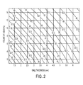
- Fig. 2 is a curve describing warm-up times for aluminum heat pipes with respect to wall thickness and water fill level according to various exemplary implementations.
- the time required for the fuser to warm-up may be an important machine characteristic in the office equipment market. Customers generally prefer as short a wait as possible for their output from a given machine. In general, minimizing the waiting time may be accomplished by keeping the fuser 'hot' in standby mode for extended periods of time, which may waste energy. Providing a machine with a fuser that warmed-up rapidly may reduce such waste of energy while still satisfying the customer with a short wait.
- Table 1 below indicates compatibility data for working fluid, wick and container.
- the heat pipe 100 may be fabricated in the form of, for example, the fuser roll 110 with the extended section 150 that may be heated.
- the components of the heat pipe 100 may be coated on the interior facing surface 130 with the protective layer 140, preferably liquid-phobic fluoropolymer such as, for example, poly(tetrafluoroethylene).
- liquid-phobic fluoropolymer such as, for example, poly(tetrafluoroethylene).
- Poly(tetrafluoroethylene) coating is hydrophobic and may promote a higher transport rate of dropwise condensation, as well as increase the gravity driven flowrate of condensed liquid droplets back from the condenser end to the evaporator end of the heat pipe 100, due to the destruction of the boundary layer.
- coating the inner surface 120 of the evaporation section 150 of the heat pipe 100 with a hydrophobic surface may also increase the critical heat flux for the onset of film boiling, which may allow for a shorter evaporator length. Additionally, the fluoropolymer coating 130 may be less susceptible to stress cracking due to thermal cycling, than other coating materials, which need to match the coefficient of thermal expansion between the coating and the substrate.
- the internal surface 130 of the heat pipe 100 may be coated by powder coating of, for example, poly(tetrafluoroethylene) or poly(tetrafluoroethylene-co-perlfuoroalkyl ether) particles, followed by sintering of particles to form a continuous protective film at about 350-400 °C.
- the internal surface 130 of the heat pipe 100 may be coated by simultaneous spin casting and drying of a liquid dispersion of Poly(tetrafluoroethylene) or poly(tetrafluoroethylene-co-perlfuoroalkyl ether) particles, followed by sintering of particles to form a continuous protective film at about 350-400 °C.
- the internal surface 130 of the heat pipe 100 may be coated by simultaneous spin casting and drying of a solution of soluble Teflon AF 2400, followed by complete solvent removal to form a continuous protective film at about 250-300 °C.
- the liquid-phobic coating may be filled with thermally conductive particles such as SiC or alumina. Depending on the filler particle loading, thermal conductivity of the resulting coating may be improved by as much as approximately 50 to 200%.
- the components of the heat pipe 100 may be coated on their interior facing surface 130 with protective layer of electroless nickel (EN) (Ni-Phosphorous or Ni-Boron alloy) poly(tetrafluoroethylene) nanocomposite.
- EN electroless nickel
- the EN containing less than about 8% phosphorous is magnetic, and thus may be used as a susceptor for induction heating.
- the poly(tetrafluoroethylene) is hydrophobic and may promote the higher transport rate of dropwise condensation as well as increasing the gravity driven flowrate of condensed liquid back from the condenser end to the evaporator end of the heat pipe.
- the electroless nickel solution containing micron-size or nanometer-size poly(tetrafluoroethylene) particles may be used to deposit the EN poly(tetrafluoroethylene) composite.
- the poly(tetrafluoroethylene) particles may be incorporated in the EN coating as the EN coating is formed.
- the resulting EN poly(tetrafluoroethylene) nanocomposite may contain up to approximately 25% by weight of poly(tetrafluoroethylene).
- the nanocomposite coating has inherently fewer imperfections. A post-coating heat treatment may then be performed to better seal the imperfections such as pores or cracks.
- the electroless nickel solution containing no poly(tetrafluoroethylene) particles may be used to deposit the EN coating in the interior surfaces of the heat pipe.
- the resulting EN surfaces may then be exposed to a dispersion containing poly(tetrafluoroethylene) micro or nanoparticles and the pores or cracks may be sealed by poly(tetrafluoroethylene) particles.
- the post-sealing heat treatment may be needed to sinter the poly(tetrafluoroethylene) particles in order to provide a better seal against water vapor.
- the thermal and rheological properties of the incorporated polymer components may be designed to self-heal or close up the induced cracks due to thermal cycling.
- Some polymer composites may require a somewhat higher temperature than the nominal fuser operating temperature in order to self-heal. If the metal coating is magnetic, the self-healing due to polymer sintering or melt flow may be achieved through a very short period of overheating in the coating with an induction coil. Table 2 indicates relative induction heating efficiencies for potential heat pipe fuser rolls. The magnetic properties of steel allow for more efficient heating than the non-magnetic stainless steel.
- Fig. 3 is an illustration of an exemplary internal configuration of a heat pipe fuser 200.
- the internal surface 200 of the heat pipe is illustrated, comprising structural features such as, for example, spiral ribs 210 superimposed over ridges 220.
- the spiral ribs are rotating along the same direction.
- the spiral ribs may act as a mechanism that facilitates liquid return flow to the evaporator section of the heat pipe.
- the augmented return flow may be necessary to prevent evaporator dry-out for heat pipe filled with a minimal amount of working fluid.
- nickel coating a steel heat pipe enables a cost effective mid-volume applications where steady state power consumption is important.
- another option for a core material in this class includes more expensive stainless steel with secondary surface treatments. Without a protective coating on the steel shell, it may be unusable with water because of non-condensable gas formation. Other working fluids are incapable of transmitting enough heat through the pipe due to lower values for their heats of vaporizations as compared to water. This may limit the thermal distribution effectiveness of the heat pipe fuser roll.
- Table 2 Relative induction heating efficiencies for potential heat fuser roll cores Material Induction Heating Efficiency Steel 85% Stainless Steel 67% Aluminium 11% Copper 7% Brass 18%
- Table 3 indicates useful temperature ranges for potential heat pipe working fluids.
- Table 3: Useful temperature range for potential heat pipe working fluids MEDIUM MELTING PT. (°C) BOILING PT, AT ATM, PRESSURE (°C) USEFUL RANGE (°C) Helium ⁇ 271 ⁇ 281 ⁇ 271 to ⁇ 269 Nitrogen ⁇ 210 -196 ⁇ 203 to ⁇ 160 Ammonie ⁇ 78 -33 ⁇ 60 to 100 Acetone ⁇ 96 57 0 to 120 Methanol ⁇ 98 64 10 to 130 Flutec PP2 ⁇ 50 78 10 to 160 Ethanol ⁇ 112 78 0 to 130 Water 0 100 30 to 200 Toluene ⁇ 95 110 50 to 200 Mercurey ⁇ 39 361 250 to 650 Sodium 98 892 600 to 1200 Lithium 179 1340 1000 to 1800 Silver 960 2212 1800 to 2300
- Fig. 4 is a flowchart illustrating an exemplary manufacturing method of an energy transfer device.
- the method starts in step S100, and continues to step S110.
- a heat pipe may be provided.
- the control continues to step S120, during which an interior coating may be provided to various portions of the heat pipe.
- the interior coating may be chemically inert so as not to react with, for instance, water, and deteriorate as a result.
- the interior coating may be liquid phobic so as to repel water and prevent it from penetrating the coating and the underlying metallic structure, and may be stable at a high temperature.
- the interior coating may have a low porosity and a low surface energy, for example, a surface energy between 0 and 50 dynes/cm.
- control continues to step S130.
- the interior coating provided in step S120 may be configured such as to exhibit spiral ribs. Configuring the interior coating to exhibit spiral ribs may be performed prior to providing the interior coating to the heat pipe, and it may be performed after the interior coating is provided to the heat pipe. Next, control continues to step S 140.
- step S 140 the various portions of the heat pipe that were coated as in, for example, during steps S120 and S130, may be joined back together to define an interior volume.
- the volume may then be evacuated, back-filled with the working fluid such as, for example, water, and hermetically sealed.
- control continues to step S 150, where the method ends.
Landscapes
- Engineering & Computer Science (AREA)
- Physics & Mathematics (AREA)
- Mechanical Engineering (AREA)
- Sustainable Development (AREA)
- Thermal Sciences (AREA)
- Life Sciences & Earth Sciences (AREA)
- General Physics & Mathematics (AREA)
- General Engineering & Computer Science (AREA)
- Fixing For Electrophotography (AREA)
- Application Of Or Painting With Fluid Materials (AREA)
- Pipeline Systems (AREA)
- General Induction Heating (AREA)
- Other Surface Treatments For Metallic Materials (AREA)
Abstract
Description
- Maintaining temperature uniformity of a fuser roll has long been a problem when varying media sizes in printing systems. In order to solve these uniformity issues, using a heat pipe as a fuser roll has been previously disclosed. Problems generally arise though in the complexity of the design of such heat pipe fuser rolls because the heat pipe generally acts as a closed system, and applying heat internally becomes difficult. Previous disclosures recommend applying heat at one end of the fuser roll, which simplifies the geometry of the subsystems. By applying all the heat at one end of the system, the incident heat flux at that end is increased, and because there is a need to minimize the amount of water in the heat pipe for instant-on applications, there is a potential for dry-out of the heat pipe evaporator. Preventing evaporator dry-out by pumping fluids using more complex interior geometries has also been proposed. The resulting interior structures are more easily constructed in tubes made out of aluminum. However, aluminum is an incompatible wall material for a heat pipe using water as a working fluid because aluminum corrodes easily in the presence of water. For this reason, the aluminum may be coated with a chemically inert layer in water-based heat pipes. For instance, the following references describe heat pipes with specifically configured internal structures: U.S. Application Serial No. (Attorney Docket No. 123346; Xerox ID # 20040097-US-NP);
US Patent No. 4,773,476 ; "Helical Guide-Type Rotating Heat Pipe", Shimizu, A. and Yamazaki, S., 6th International Heat Pipe Conference, 1987; "Heat Transfer and Internal Flow Characteristics of a Coil-Inserted Rotating Heat Pipe", Lee, J. and Kim, C., International Journal of Heat and Mass Transfer, 2001. - Differences in the preferred materials for induction heating, heat pipes, and fuser rolls generally make their combination difficult. Induction heating is preferably used with a magnetic, electrically resistive metal such as, for example, steel. A fuser roll manufacturer generally prefers a low-cost, light-weight, easy-to-process metal such as, for example, aluminum. On the other hand, water as the working fluid is preferred as a heat pipe operating in a temperature range of a typical fuser, which can be 150-250°C. At all temperatures, water vapor is reactive with the preferred core materials.
- The present invention provides:
- (1) an energy transfer device, comprising:
- a heat pipe; and
- an interior coating to at least a portion of an interior surface of the heat pipe; wherein
- the interior coating comprises at least one of the properties selected from chemically inert, liquid phobic, stable at high temperature, of low porosity and of low surface energy;
- (2) the energy transfer device of (1), wherein the energy transfer device comprises at least one of a fuser roll, a photoreceptor, and a paper transport device;
- (3) the energy transfer device of (2), wherein the heat pipe comprises at least one of a steel heat pipe and an aluminum heat pipe;
- (4) the energy transfer device of (2), further comprising an inductive heater to heat the heat pipe;
- (5) the energy transfer device of (4), wherein the inductive heater comprises induction coils located at least at one of one end of the heat pipe, along a length of the heat pipe, both ends of the heat pipe and inside the heat pipe;
- (6) the energy transfer device of (3), wherein an interior surface of the aluminum heat pipe comprises interior surface patterns;
- (7) the energy transfer device of (6), wherein the interior surface geometries comprise spiral ribs;
- (8) the energy transfer device of (1), wherein the interior coating is chemically inert to at least one of water and steam;
- (9) the energy transfer device of (1), wherein the interior coating comprises at least one of nickel, chromium, tantalum, copper, zinc, poly(tetrafluoroethylene), poly(tetrafluoroethylene-co-perlfuoroalkyl ether), and a metal composite;
- (10) the energy transfer device of (1), wherein the interior coating has a thickness in a
range 5 µm to 25 µm, and porosity is less than one spot per square inch; - (11) the energy transfer device of (1), wherein the interior coating comprises at least one of a nickel-phosphorus alloy and a nickel-boron alloy;
- (12) the energy transfer device of (9), wherein the metal composite comprises at least one of electroless nickel, poly(tetrafluoroethylene), nickel-phosphorous and nickel-boron;
- (13) a manufacturing method of an energy transfer device, comprising:
- providing a heat pipe; and
- providing an interior coating to an interior surface of at least a portion of the heat pipe, the interior coating comprising at least one of the properties selected from chemically inert, liquid phobic, stable at high temperature, of low porosity and of low surface energy;
- (14) the method of (13), further comprising providing a surface pattern to the interior surface of at least a portion of the heat pipe;
- (15) the manufacturing method of (13), wherein providing an interior coating comprises:
- coating an inside surface of the heat pipe with a powder comprising particles; and
- sintering the particles to form a continuous protective film;
- (16) the manufacturing method of (15), wherein the powder comprises at least one of poly(tetrafluoroethylene), poly(tetrafluoroethylene-co-perlfuoroalkyl ether), silicon carbide and alumina;
- (17) the manufacturing method of (13), wherein sintering the particles is performed in a temperature range of about 300 °C to about 500 °C;
- (18) the manufacturing method of (13), wherein providing an interior coating comprises:
- simultaneous spin casting a solution comprising particles and a solvent;
- drying the solution; and
- removing the solvent to form a continuous protective film;
- (19) the manufacturing method of (18), wherein removing the solvent is performed in a temperature range of about 250 °C to about 300 °C;
- (20) the manufacturing method of (13), wherein providing an interior coating comprises:
- coating an interior surface of the heat pipe with a coating material comprising one of electroless nickel, a nickel-phosphorous alloy, a nickel-boron alloy;
- (21) the method of (13), further comprising providing an inductive heater to heat the heat pipe;
- (22) a xerographic device comprising the energy transfer device of (1); and
- (23) a xerographic system comprising:
- a heat pipe; and
- a controller that controls an operation of the heat pipe in the xerographic system; wherein
- an interior coating to at least a portion of an interior surface of the heat pipe is provided; and
- the interior coating comprises at least one of the properties selected from chemically inert, liquid phobic, stable at high temperature, of low porosity and of low surface energy.
- Under normal operating conditions, aluminum and water are incompatible as heat pipe materials because thermal cycling conditions may cause aluminum to undergo stress cracking. Thermal stress cracking is generally due to the difference between the thermal expansion coefficients of aluminum and its oxide, and does not occur at room temperature. Once a crack has formed, water is then exposed to bare aluminum, which then corrodes. Accordingly, water film condensation on the coating limits the choices of coating material. At elevated temperatures, the water and iron in the steel may react to corrode the steel and form a non-condensable gas in the heat pipe, thus limiting its effectiveness. Porosity, coating imperfections, and a thermal expansion mismatch between the coating the underlying metal may cause stress cracking and thus limits the choices of coating material.
- In light of these problems and shortcomings, various exemplary embodiments of devices and methods may provide an energy transfer device that includes a heat pipe and an interior coating to the heat pipe, wherein the heat pipe is to provide uniform heating and the interior coating is at least one of chemically inert, liquid phobic, stable at a high temperature, low porosity and low surface energy.
- Moreover, various exemplary implementations may provide a manufacturing method for an energy transfer device that includes providing a heat pipe and providing an interior coating to the heat pipe, wherein the heat pipe is to provide uniform heating and the interior coating is at least one of chemically inert, liquid phobic, stable at high temperature, low porosity, and low surface energy.
- Various exemplary implementations of systems are described in detail with reference to the following figures, wherein:
- Fig. 1 is an illustration of an exemplary heat pipe according to various implementations;
- Fig. 2 is a curve describing warm up times for aluminum heat pipes with respect to wall thickness and water fill level according to various exemplary implementations;
- Fig. 3 is an illustration of an exemplary internal configuration of a heat pipe fuser according to various exemplary implementations; and
- Fig. 4 is a flowchart illustrating an exemplary manufacturing method of an energy transfer device, according to various exemplary implementations.
- These and other features and advantages are described in, or are apparent from, the following detailed description of various exemplary embodiments.
- Fig. 1 is an illustration of an
exemplary heat pipe 100 according to various implementations. Theheat pipe 100 may be fabricated from aluminum in the form of afuser roll 110 with an internal structure that facilitates the return flow of liquid to anevaporator section 120. According to various implementations, the components of theheat pipe 100 may be coated on interior facing surfaces 130 of thefuser roll 110 with a protective layer used as aninterior coating 140 such as, for example, nickel. Theinterior coating 140 may be of significant thickness, for example between 5µm and 25 µm, to minimize its porosity to about less than one spot per square centimeter, and in some cases to less than about one spot per square inch. Porosity is measured on the basis of measurement techniques described in ASTM B 733 - 97. According to various implementations, after coating, the components of theheat pipe 100 may then be joined together to define an interior volume. The volume may then be evacuated, back-filled with the working fluid, preferably water, and hermetically sealed. According to various exemplary implementations, coating the interior surfaces of thealuminum fuser roll 110 with nickel may provide a barrier to the corrosion of thefuser roll 110, thus maintaining safe operation of theheat pipe 100. - Nickel coating of steel may be used because of the magnetic properties of nickel, its close-packed structure when alloyed with phosphorus, and its similar coefficient of thermal expansion as compared to steel. The coefficient of thermal expansion of electroless nickel generally ranges from 12-14.5 ppm/°C for a few % up to 15% phosphorous (steel - 12 ppm/°C). Additionally, a nickel coating may be alloyed with boron to provide similar characteristics as the phosphorus alloy with improved ductility. Electroless nickel-phosphorus and nickel-boron coating of steel is a well documented process and provides superior corrosion resistance to stainless steel at a comparable or cheaper cost. An
extended section 150 of the heat pipe may be placed in an alternating field generated by the induction coil and the fuser is operational. - In addition to the protective characteristics of nickel coating, nickel coating may also act as a magnetic susceptor in, for example, an induction heating application. Coating the
non-magnetic fuser roll 110 made of, for example, aluminum, with a magnetic material such as, for example, nickel, may provide a heat source on the interior of thefuser roll 110, thus increasing the induction heating efficiency of thenon-magnetic fuser roll 110. - Generally, nickel coating an
aluminum fuser roll 110 enables low end instant-on applications. Without a protective coating, the aluminum shell may be unusable with water, which happens to generally be the most suitable working fluid. Also, without special internal structures that are most easily machined into aluminum, the amount of water necessary to avoid evaporator dry-out may limit the warm-up times available for instant-on applications. - Fig. 2 is a curve describing warm-up times for aluminum heat pipes with respect to wall thickness and water fill level according to various exemplary implementations. The time required for the fuser to warm-up may be an important machine characteristic in the office equipment market. Customers generally prefer as short a wait as possible for their output from a given machine. In general, minimizing the waiting time may be accomplished by keeping the fuser 'hot' in standby mode for extended periods of time, which may waste energy. Providing a machine with a fuser that warmed-up rapidly may reduce such waste of energy while still satisfying the customer with a short wait. Table 1 below indicates compatibility data for working fluid, wick and container.
Table 1 Material Water Acetone Ammonia Methanol Copper RURU NU RU Aluminium GNC RL RU NR Stainless Steel GNT PC RU GNT Nickel PC PC RU RL Refrasil RU RU RU RU Material Dow-A Dow-E Freon 11 Freon 113 Copper RU RU RU RU Aluminium UK NR RU RU Stainless Steel RU RU RU RU Nickel RU RL UK UK Refrasil RU UK UK RU, recommended by past successful usage; RL, recommended by literature; PC, probably compatible; NR, not recommended; NU, not used; UK, unknown; GNC, generation of gas at all temperatures; CNT, generation of gas at elevated temperatures when oxide is present. - According to various exemplary implementations, the
heat pipe 100 may be fabricated in the form of, for example, thefuser roll 110 with theextended section 150 that may be heated. According to various exemplary implementations, the components of theheat pipe 100 may be coated on theinterior facing surface 130 with theprotective layer 140, preferably liquid-phobic fluoropolymer such as, for example, poly(tetrafluoroethylene). Poly(tetrafluoroethylene) coating is hydrophobic and may promote a higher transport rate of dropwise condensation, as well as increase the gravity driven flowrate of condensed liquid droplets back from the condenser end to the evaporator end of theheat pipe 100, due to the destruction of the boundary layer. According to various exemplary embodiments, coating theinner surface 120 of theevaporation section 150 of theheat pipe 100 with a hydrophobic surface may also increase the critical heat flux for the onset of film boiling, which may allow for a shorter evaporator length. Additionally, thefluoropolymer coating 130 may be less susceptible to stress cracking due to thermal cycling, than other coating materials, which need to match the coefficient of thermal expansion between the coating and the substrate. - The
internal surface 130 of theheat pipe 100 may be coated by powder coating of, for example, poly(tetrafluoroethylene) or poly(tetrafluoroethylene-co-perlfuoroalkyl ether) particles, followed by sintering of particles to form a continuous protective film at about 350-400 °C. Theinternal surface 130 of theheat pipe 100 may be coated by simultaneous spin casting and drying of a liquid dispersion of Poly(tetrafluoroethylene) or poly(tetrafluoroethylene-co-perlfuoroalkyl ether) particles, followed by sintering of particles to form a continuous protective film at about 350-400 °C. Theinternal surface 130 of theheat pipe 100 may be coated by simultaneous spin casting and drying of a solution of soluble Teflon AF 2400, followed by complete solvent removal to form a continuous protective film at about 250-300 °C. In addition, the liquid-phobic coating may be filled with thermally conductive particles such as SiC or alumina. Depending on the filler particle loading, thermal conductivity of the resulting coating may be improved by as much as approximately 50 to 200%. - The components of the
heat pipe 100 may be coated on their interior facingsurface 130 with protective layer of electroless nickel (EN) (Ni-Phosphorous or Ni-Boron alloy) poly(tetrafluoroethylene) nanocomposite. The EN containing less than about 8% phosphorous is magnetic, and thus may be used as a susceptor for induction heating. The poly(tetrafluoroethylene) is hydrophobic and may promote the higher transport rate of dropwise condensation as well as increasing the gravity driven flowrate of condensed liquid back from the condenser end to the evaporator end of the heat pipe. The electroless nickel solution containing micron-size or nanometer-size poly(tetrafluoroethylene) particles may be used to deposit the EN poly(tetrafluoroethylene) composite. The poly(tetrafluoroethylene) particles may be incorporated in the EN coating as the EN coating is formed. The resulting EN poly(tetrafluoroethylene) nanocomposite may contain up to approximately 25% by weight of poly(tetrafluoroethylene). The nanocomposite coating has inherently fewer imperfections. A post-coating heat treatment may then be performed to better seal the imperfections such as pores or cracks. - The electroless nickel solution containing no poly(tetrafluoroethylene) particles may be used to deposit the EN coating in the interior surfaces of the heat pipe. The resulting EN surfaces may then be exposed to a dispersion containing poly(tetrafluoroethylene) micro or nanoparticles and the pores or cracks may be sealed by poly(tetrafluoroethylene) particles. The post-sealing heat treatment may be needed to sinter the poly(tetrafluoroethylene) particles in order to provide a better seal against water vapor. The thermal and rheological properties of the incorporated polymer components may be designed to self-heal or close up the induced cracks due to thermal cycling. Some polymer composites may require a somewhat higher temperature than the nominal fuser operating temperature in order to self-heal. If the metal coating is magnetic, the self-healing due to polymer sintering or melt flow may be achieved through a very short period of overheating in the coating with an induction coil. Table 2 indicates relative induction heating efficiencies for potential heat pipe fuser rolls. The magnetic properties of steel allow for more efficient heating than the non-magnetic stainless steel.
- Fig. 3 is an illustration of an exemplary internal configuration of a
heat pipe fuser 200. In Fig. 3, theinternal surface 200 of the heat pipe is illustrated, comprising structural features such as, for example,spiral ribs 210 superimposed overridges 220. The spiral ribs are rotating along the same direction. The spiral ribs may act as a mechanism that facilitates liquid return flow to the evaporator section of the heat pipe. The augmented return flow may be necessary to prevent evaporator dry-out for heat pipe filled with a minimal amount of working fluid. - Generally, nickel coating a steel heat pipe enables a cost effective mid-volume applications where steady state power consumption is important. According to various exemplary implementations, another option for a core material in this class includes more expensive stainless steel with secondary surface treatments. Without a protective coating on the steel shell, it may be unusable with water because of non-condensable gas formation. Other working fluids are incapable of transmitting enough heat through the pipe due to lower values for their heats of vaporizations as compared to water. This may limit the thermal distribution effectiveness of the heat pipe fuser roll.
Table 2: Relative induction heating efficiencies for potential heat fuser roll cores Material Induction Heating Efficiency Steel 85% Stainless Steel 67% Aluminium 11% Copper 7% Brass 18% - Table 3 indicates useful temperature ranges for potential heat pipe working fluids.
Table 3: Useful temperature range for potential heat pipe working fluids MEDIUM MELTING PT. (°C) BOILING PT, AT ATM, PRESSURE (°C) USEFUL RANGE (°C) Helium ~271 ~281 ~271 to ~269 Nitrogen ~210 -196 ~203 to ~160 Ammonie ~78 -33 ~60 to 100 Acetone ~96 57 0 to 120 Methanol ~98 64 10 to 130 Flutec PP2 ~50 78 10 to 160 Ethanol ~112 78 0 to 130 Water 0 100 30 to 200 Toluene ~95 110 50 to 200 Mercurey ~39 361 250 to 650 Sodium 98 892 600 to 1200 Lithium 179 1340 1000 to 1800 Silver 960 2212 1800 to 2300 - Fig. 4 is a flowchart illustrating an exemplary manufacturing method of an energy transfer device. In Fig. 4, the method starts in step S100, and continues to step S110. During step S110, a heat pipe may be provided. The control continues to step S120, during which an interior coating may be provided to various portions of the heat pipe. The interior coating may be chemically inert so as not to react with, for instance, water, and deteriorate as a result. The interior coating may be liquid phobic so as to repel water and prevent it from penetrating the coating and the underlying metallic structure, and may be stable at a high temperature. The interior coating may have a low porosity and a low surface energy, for example, a surface energy between 0 and 50 dynes/cm. Next, control continues to step S130.
- During step S130, the interior coating provided in step S120 may be configured such as to exhibit spiral ribs. Configuring the interior coating to exhibit spiral ribs may be performed prior to providing the interior coating to the heat pipe, and it may be performed after the interior coating is provided to the heat pipe. Next, control continues to step
S 140. - During
step S 140, the various portions of the heat pipe that were coated as in, for example, during steps S120 and S130, may be joined back together to define an interior volume. The volume may then be evacuated, back-filled with the working fluid such as, for example, water, and hermetically sealed. Next, control continues to stepS 150, where the method ends. - It will be appreciated that variants of the above-disclosed and other features and functions, or alternatives thereof, may be desirably combined into many other different systems or applications. Also, various presently unforeseen or unanticipated alternatives, modifications, variations or improvements therein may be subsequently made by those skilled in the art which are also intended to be encompassed by the following claims.
Claims (10)
- An energy transfer device, comprising:a heat pipe; andan interior coating to at least a portion of an interior surface of the heat pipe; whereinthe interior coating comprises at least one of the properties selected from chemically inert, liquid phobic, stable at high temperature, of low porosity and of low surface energy.
- The energy transfer device of claim 1, wherein the energy transfer device comprises at least one of a fuser roll, a photoreceptor, and a paper transport device.
- The energy transfer device of claim 2, wherein the heat pipe comprises at least one of a steel heat pipe and an aluminum heat pipe.
- The energy transfer device of claim 2, further comprising an inductive heater to heat the heat pipe.
- The energy transfer device of claim 4, wherein the inductive heater comprises induction coils located at least at one of one end of the heat pipe, along a length of the heat pipe, both ends of the heat pipe and inside the heat pipe.
- The energy transfer device of claim 3, wherein an interior surface of the aluminum heat pipe comprises interior surface patterns.
- The energy transfer device of claim 6, wherein the interior surface geometries comprise spiral ribs.
- A manufacturing method of an energy transfer device, comprising:providing a heat pipe; andproviding an interior coating to an interior surface of at least a portion of the heat pipe, the interior coating comprising at least one of the properties selected from chemically inert, liquid phobic, stable at high temperature, of low porosity and of low surface energy.
- A xerographic device comprising the energy transfer device of claim 1.
- A xerographic system comprising:a heat pipe; anda controller that controls an operation of the heat pipe in the xerographic system; whereinan interior coating to at least a portion of an interior surface of the heat pipe is provided; andthe interior coating comprises at least one of the properties selected from chemically inert, liquid phobic, stable at high temperature, of low porosity and of low surface energy.
Applications Claiming Priority (1)
| Application Number | Priority Date | Filing Date | Title |
|---|---|---|---|
| US11/094,423 US20060222423A1 (en) | 2005-03-31 | 2005-03-31 | Heat-pipe fuser roll with internal coating |
Publications (2)
| Publication Number | Publication Date |
|---|---|
| EP1715274A2 true EP1715274A2 (en) | 2006-10-25 |
| EP1715274A3 EP1715274A3 (en) | 2008-09-03 |
Family
ID=36952841
Family Applications (1)
| Application Number | Title | Priority Date | Filing Date |
|---|---|---|---|
| EP06111798A Withdrawn EP1715274A3 (en) | 2005-03-31 | 2006-03-28 | Heat-Pipe with Internal Coating |
Country Status (3)
| Country | Link |
|---|---|
| US (1) | US20060222423A1 (en) |
| EP (1) | EP1715274A3 (en) |
| JP (1) | JP2006284167A (en) |
Families Citing this family (17)
| Publication number | Priority date | Publication date | Assignee | Title |
|---|---|---|---|---|
| US20060219390A1 (en) * | 2005-03-31 | 2006-10-05 | Xerox Corporation | Self-pumping heat-pipe fuser roll |
| JP4778735B2 (en) * | 2005-06-24 | 2011-09-21 | 東芝機械株式会社 | Manufacturing method of glass mold |
| JP2007150192A (en) * | 2005-11-30 | 2007-06-14 | Toshiba Corp | Information processing apparatus including a heat radiator having a heat pipe |
| KR101053701B1 (en) * | 2006-12-14 | 2011-08-02 | 도시바 기카이 가부시키가이샤 | Manufacturing method of mold for glass molding |
| JP5019102B2 (en) * | 2006-12-14 | 2012-09-05 | 東芝機械株式会社 | Manufacturing method of glass mold |
| US8853593B2 (en) * | 2008-03-19 | 2014-10-07 | GM Global Technology Operations LLC | Heat pipe cooling system for use with a welding torch |
| US8438847B2 (en) * | 2008-12-25 | 2013-05-14 | Industrial Technology Research Institute | Heat-pipe electric power generating device and hydrogen/oxygen gas generating apparatus and internal combustion engine system having the same |
| TWI409382B (en) * | 2008-12-25 | 2013-09-21 | 財團法人工業技術研究院 | Heat pipe type power generation element and hydrogen/oxygen generating device and internal combustion engine system having the same |
| US8855542B2 (en) * | 2011-08-26 | 2014-10-07 | Kabushiki Kaisha Toshiba | Fuser, image forming apparatus, and image forming method |
| US20130180593A1 (en) * | 2012-01-16 | 2013-07-18 | Exxonmobil Research And Engineering Company | Heat pipe with controlled fluid charge and hydrophobic coating |
| KR101510261B1 (en) * | 2012-10-10 | 2015-04-10 | 정춘식 | Carbon nano-particle coating method of heatpipe |
| US9470459B2 (en) * | 2013-07-01 | 2016-10-18 | Asia Vital Components Co., Ltd. | Support structure for heat dissipation unit |
| FR3013437B1 (en) * | 2013-11-20 | 2015-12-18 | Valeo Systemes Thermiques | COATING FOR HEAT EXCHANGER |
| JP2016130777A (en) * | 2015-01-14 | 2016-07-21 | 京セラドキュメントソリューションズ株式会社 | Fixing apparatus and image forming apparatus |
| WO2019039445A1 (en) | 2017-08-23 | 2019-02-28 | 古河電気工業株式会社 | Heat pipe and heat pipe production method |
| US11054199B2 (en) | 2019-04-12 | 2021-07-06 | Rheem Manufacturing Company | Applying coatings to the interior surfaces of heat exchangers |
| JP2024531591A (en) * | 2021-09-07 | 2024-08-29 | ケーエムダブリュ・インコーポレーテッド | Vapor chamber and method of manufacturing same |
Family Cites Families (19)
| Publication number | Priority date | Publication date | Assignee | Title |
|---|---|---|---|---|
| US2766200A (en) * | 1952-09-04 | 1956-10-09 | Westinghouse Electric Corp | Water heating apparatus |
| CH512715A (en) * | 1968-05-25 | 1971-09-15 | Metallgesellschaft Ag | Use of refractory metals as wall material for heat pipes |
| CA960413A (en) * | 1971-01-08 | 1975-01-07 | Robert F. Keller | Method of making a heat pipe and wick therein |
| US4211595A (en) * | 1978-10-10 | 1980-07-08 | The Kendall Company | Method of coating pipe |
| DE3433984C2 (en) * | 1984-09-15 | 1986-07-24 | Daimler-Benz Ag, 7000 Stuttgart | Heat pipe made of aluminum or steel |
| US4885129A (en) * | 1988-10-24 | 1989-12-05 | The United States Of America As Represented By The Secretary Of The Air Force | Method of manufacturing heat pipe wicks |
| JP2793978B2 (en) * | 1995-06-27 | 1998-09-03 | 日東工業株式会社 | Fixing roll for electrophotographic apparatus and method of manufacturing the same |
| JPH09119789A (en) * | 1995-10-24 | 1997-05-06 | Mitsubishi Materials Corp | Heat pipe manufacturing method |
| US5699852A (en) * | 1996-08-22 | 1997-12-23 | Korea Institute Of Energy Research | Heat exchanger having a resin-coated pipe |
| AU723560B2 (en) * | 1997-01-13 | 2000-08-31 | American Roller Company, Llc | Heated roller with integral heat pipe |
| JPH11282294A (en) * | 1998-03-30 | 1999-10-15 | Ricoh Co Ltd | Fixing device |
| JPH11304381A (en) * | 1998-04-23 | 1999-11-05 | Fujikura Ltd | heat pipe |
| US6799628B1 (en) * | 2000-07-20 | 2004-10-05 | Honeywell International Inc. | Heat exchanger having silicon nitride substrate for mounting high power electronic components |
| DE60110183T2 (en) * | 2000-10-30 | 2006-03-09 | Ricoh Company, Ltd. | Fixing roller, this fixing device using, as well as this fixing device using image forming apparatus |
| KR100400003B1 (en) * | 2000-12-22 | 2003-09-29 | 삼성전자주식회사 | Fusing roller apparatus of electrophotographic image forming apparatus |
| US6580896B2 (en) * | 2000-12-22 | 2003-06-17 | Samsung Electronics Co., Ltd. | Fusing roller assembly for electrophotographic image forming apparatus |
| US6580895B2 (en) * | 2001-03-28 | 2003-06-17 | Hewlett-Packard Development Company, L.P. | Fusing system including a heat distribution mechanism |
| US6749894B2 (en) * | 2002-06-28 | 2004-06-15 | Surface Engineered Products Corporation | Corrosion-resistant coatings for steel tubes |
| US7314785B2 (en) * | 2003-10-24 | 2008-01-01 | Semiconductor Energy Laboratory Co., Ltd. | Display device and manufacturing method thereof |
-
2005
- 2005-03-31 US US11/094,423 patent/US20060222423A1/en not_active Abandoned
-
2006
- 2006-03-27 JP JP2006086146A patent/JP2006284167A/en not_active Withdrawn
- 2006-03-28 EP EP06111798A patent/EP1715274A3/en not_active Withdrawn
Also Published As
| Publication number | Publication date |
|---|---|
| JP2006284167A (en) | 2006-10-19 |
| EP1715274A3 (en) | 2008-09-03 |
| US20060222423A1 (en) | 2006-10-05 |
Similar Documents
| Publication | Publication Date | Title |
|---|---|---|
| US20060222423A1 (en) | Heat-pipe fuser roll with internal coating | |
| US6516142B2 (en) | Internal heating element for pipes and tubes | |
| TW382876B (en) | Improved polymeric immersion heating element with skeletal support and optional heat transfer fins | |
| JP5008207B2 (en) | Improved capillary force vaporizer | |
| Sarwar et al. | Subcooled flow boiling CHF enhancement with porous surface coatings | |
| KR940001087B1 (en) | Directly-heating roller for fixing toner images | |
| US6445902B1 (en) | Simplified fusing system | |
| WO2002090836A1 (en) | Electric water heater, liquid heater, steam generator | |
| US6580061B2 (en) | Durable, non-reactive, resistive-film heater | |
| CN101158508B (en) | Electrothermic metal phase changing accumulation energy hot-water hot blast dual-purpose device | |
| US7989739B2 (en) | Electric heater assembly | |
| JP2002251101A (en) | Fixing roller assembly for electrophotographic image forming apparatus and method of manufacturing the same | |
| US20070202321A1 (en) | Thermally conductive microporous coating | |
| WO2008014148A2 (en) | Fuser roller | |
| CN219182802U (en) | Heater and aerosol generating device | |
| US6663914B2 (en) | Method for adhering a resistive coating to a substrate | |
| JP2005114352A (en) | Fluid heating device | |
| CN107484274A (en) | A kind of erosion resisting insulation safe liquid heating tube | |
| US6479094B2 (en) | Method for forming a resistor | |
| JP2007155310A (en) | Heat conductive assembly for water heater and manufacturing method of heat conductive assembly | |
| JP2026007624A (en) | heater | |
| CN207321569U (en) | A kind of stable durable security liquid heating pipe | |
| US20010028915A1 (en) | Method for adjusting resistivity of a film heater | |
| CN221763519U (en) | A heating system | |
| JP2008304090A (en) | Liquid heating device |
Legal Events
| Date | Code | Title | Description |
|---|---|---|---|
| PUAI | Public reference made under article 153(3) epc to a published international application that has entered the european phase |
Free format text: ORIGINAL CODE: 0009012 |
|
| AK | Designated contracting states |
Kind code of ref document: A2 Designated state(s): AT BE BG CH CY CZ DE DK EE ES FI FR GB GR HU IE IS IT LI LT LU LV MC NL PL PT RO SE SI SK TR |
|
| AX | Request for extension of the european patent |
Extension state: AL BA HR MK YU |
|
| RIN1 | Information on inventor provided before grant (corrected) |
Inventor name: POLATKAN, OSMAN T. Inventor name: KLADIAS, NICHOLAS Inventor name: PAN, DAVID H. Inventor name: DOMOTO, GERALD A. Inventor name: BOTT, DONALD M. Inventor name: DEJONG, JEREMY C. |
|
| PUAL | Search report despatched |
Free format text: ORIGINAL CODE: 0009013 |
|
| AK | Designated contracting states |
Kind code of ref document: A3 Designated state(s): AT BE BG CH CY CZ DE DK EE ES FI FR GB GR HU IE IS IT LI LT LU LV MC NL PL PT RO SE SI SK TR |
|
| AX | Request for extension of the european patent |
Extension state: AL BA HR MK YU |
|
| RIC1 | Information provided on ipc code assigned before grant |
Ipc: G03G 15/20 20060101ALI20080725BHEP Ipc: F28D 15/04 20060101AFI20060918BHEP |
|
| STAA | Information on the status of an ep patent application or granted ep patent |
Free format text: STATUS: THE APPLICATION IS DEEMED TO BE WITHDRAWN |
|
| 18D | Application deemed to be withdrawn |
Effective date: 20081001 |