EP1714909A1 - Extruded plastic corner post - Google Patents
Extruded plastic corner post Download PDFInfo
- Publication number
- EP1714909A1 EP1714909A1 EP06016173A EP06016173A EP1714909A1 EP 1714909 A1 EP1714909 A1 EP 1714909A1 EP 06016173 A EP06016173 A EP 06016173A EP 06016173 A EP06016173 A EP 06016173A EP 1714909 A1 EP1714909 A1 EP 1714909A1
- Authority
- EP
- European Patent Office
- Prior art keywords
- bend
- corner post
- segment
- extending
- rib
- Prior art date
- Legal status (The legal status is an assumption and is not a legal conclusion. Google has not performed a legal analysis and makes no representation as to the accuracy of the status listed.)
- Granted
Links
- 239000003000 extruded plastic Substances 0.000 title claims abstract description 10
- 230000001154 acute effect Effects 0.000 claims description 3
- 239000011324 bead Substances 0.000 description 12
- 230000006835 compression Effects 0.000 description 3
- 238000007906 compression Methods 0.000 description 3
- 238000001125 extrusion Methods 0.000 description 3
- 230000035939 shock Effects 0.000 description 3
- 238000000034 method Methods 0.000 description 2
- 238000012986 modification Methods 0.000 description 2
- 230000004048 modification Effects 0.000 description 2
- 238000004806 packaging method and process Methods 0.000 description 2
- 239000004033 plastic Substances 0.000 description 2
- 238000012546 transfer Methods 0.000 description 2
- 238000010276 construction Methods 0.000 description 1
- 238000013461 design Methods 0.000 description 1
- 230000000694 effects Effects 0.000 description 1
- 239000002184 metal Substances 0.000 description 1
- 229920000642 polymer Polymers 0.000 description 1
- 238000012360 testing method Methods 0.000 description 1
Images



Classifications
-
- B—PERFORMING OPERATIONS; TRANSPORTING
- B65—CONVEYING; PACKING; STORING; HANDLING THIN OR FILAMENTARY MATERIAL
- B65D—CONTAINERS FOR STORAGE OR TRANSPORT OF ARTICLES OR MATERIALS, e.g. BAGS, BARRELS, BOTTLES, BOXES, CANS, CARTONS, CRATES, DRUMS, JARS, TANKS, HOPPERS, FORWARDING CONTAINERS; ACCESSORIES, CLOSURES, OR FITTINGS THEREFOR; PACKAGING ELEMENTS; PACKAGES
- B65D81/00—Containers, packaging elements, or packages, for contents presenting particular transport or storage problems, or adapted to be used for non-packaging purposes after removal of contents
- B65D81/02—Containers, packaging elements, or packages, for contents presenting particular transport or storage problems, or adapted to be used for non-packaging purposes after removal of contents specially adapted to protect contents from mechanical damage
- B65D81/05—Containers, packaging elements, or packages, for contents presenting particular transport or storage problems, or adapted to be used for non-packaging purposes after removal of contents specially adapted to protect contents from mechanical damage maintaining contents at spaced relation from package walls, or from other contents
- B65D81/053—Corner, edge or end protectors
- B65D81/054—Protectors contacting two generally perpendicular surfaces of the packaged article, e.g. edge protectors
-
- B—PERFORMING OPERATIONS; TRANSPORTING
- B65—CONVEYING; PACKING; STORING; HANDLING THIN OR FILAMENTARY MATERIAL
- B65D—CONTAINERS FOR STORAGE OR TRANSPORT OF ARTICLES OR MATERIALS, e.g. BAGS, BARRELS, BOTTLES, BOXES, CANS, CARTONS, CRATES, DRUMS, JARS, TANKS, HOPPERS, FORWARDING CONTAINERS; ACCESSORIES, CLOSURES, OR FITTINGS THEREFOR; PACKAGING ELEMENTS; PACKAGES
- B65D2581/00—Containers, packaging elements, or packages, for contents presenting particular transport or storage problems, or adapted to be used for non-packaging purposes after removal of contents
- B65D2581/02—Containers, packaging elements, or packages, for contents presenting particular transport or storage problems, or adapted to be used for non-packaging purposes after removal of contents specially adapted to protect contents from mechanical damage
- B65D2581/05—Containers, packaging elements, or packages, for contents presenting particular transport or storage problems, or adapted to be used for non-packaging purposes after removal of contents specially adapted to protect contents from mechanical damage maintaining contents at spaced relation from package walls, or from other contents
- B65D2581/051—Details of packaging elements for maintaining contents at spaced relation from package walls, or from other contents
- B65D2581/052—Materials
- B65D2581/055—Plastic in general, e.g. foamed plastic, molded plastic, extruded plastic
-
- Y—GENERAL TAGGING OF NEW TECHNOLOGICAL DEVELOPMENTS; GENERAL TAGGING OF CROSS-SECTIONAL TECHNOLOGIES SPANNING OVER SEVERAL SECTIONS OF THE IPC; TECHNICAL SUBJECTS COVERED BY FORMER USPC CROSS-REFERENCE ART COLLECTIONS [XRACs] AND DIGESTS
- Y10—TECHNICAL SUBJECTS COVERED BY FORMER USPC
- Y10T—TECHNICAL SUBJECTS COVERED BY FORMER US CLASSIFICATION
- Y10T428/00—Stock material or miscellaneous articles
- Y10T428/13—Hollow or container type article [e.g., tube, vase, etc.]
- Y10T428/1352—Polymer or resin containing [i.e., natural or synthetic]
- Y10T428/139—Open-ended, self-supporting conduit, cylinder, or tube-type article
-
- Y—GENERAL TAGGING OF NEW TECHNOLOGICAL DEVELOPMENTS; GENERAL TAGGING OF CROSS-SECTIONAL TECHNOLOGIES SPANNING OVER SEVERAL SECTIONS OF THE IPC; TECHNICAL SUBJECTS COVERED BY FORMER USPC CROSS-REFERENCE ART COLLECTIONS [XRACs] AND DIGESTS
- Y10—TECHNICAL SUBJECTS COVERED BY FORMER USPC
- Y10T—TECHNICAL SUBJECTS COVERED BY FORMER US CLASSIFICATION
- Y10T428/00—Stock material or miscellaneous articles
- Y10T428/24—Structurally defined web or sheet [e.g., overall dimension, etc.]
- Y10T428/24628—Nonplanar uniform thickness material
Definitions
- This patent relates to packaging for products such as washers, dryers and refrigerators. More particularly, this patent relates to an extruded plastic corner post for protecting packaged products from axial and lateral forces.
- Warehousing and distribution environments drive the need for devices that protect products from both axial (vertical) and lateral (horizontal) forces.
- Axial forces mainly are caused by stacking packaged products in warehouses.
- Lateral forces can be caused by stacking, clamp handling and basiloid handling, and also by collisions inherent in warehouse and distribution systems. For instance, it is not uncommon to move packaged appliances using clamp trucks in a block three units high, three units across and two units deep. Such clamp handling can impart lateral forces on the packaged products of up to 2,500 PSI.
- Laminated corner posts consisting essentially of hollow paper tubes are a popular means for supporting and cushioning the corners of packaged appliances during storage and transport.
- many laminated paper corner posts comprises beaded structures that are designed to fold over on themselves. Once the paper corner post is folded upon itself, the lateral force is directed through the folded corner post to the structural frame of the packaged appliance, thereby protecting the relatively weaker sidewalls.
- paper corner posts that fold over and lose their original shape are well suited to protect appliances from damage, they do not prevent the container surrounding the appliance from collapsing inwardly when the container is subjected to large lateral forces.
- Laminated paper support posts also can degrade in high humidity or wet conditions, which can occur during assembly line product testing.
- Another object of the invention is to provide a corner post that does not degrade in high humidity or wet conditions.
- Still another object of the invention is to provide a corner post that maintains the distance between the container and the product, thereby preventing the container from collapsing inwardly.
- Yet another object of the present invention is to provide a corner post having enhanced axial strength.
- the present invention is an elongated extruded plastic corner post for protecting a packaged product.
- the corner post comprises an outer wall and an inner wall joined at the ends to define a substantially L-shaped cylindrical space therebetween, and one or more integrally formed ribs connecting opposing faces of the inner and outer walls.
- the ribs may be planar or arcuately shaped. If the ribs are planar, they may be perpendicular to the inner and outer walls or set obliquely thereto.
- the tube type corner post may be formed with cut out portions to accommodate and protect protruding components of the packaged product, such as handles and the like.
- the inner and outer walls of the corner post may be formed with beads to enhance the axial strength of the post.
- the tube type corner post is best used with appliances and other products having thin walls mounted on a relatively strong structural framework.
- the tube type corner post protects the packaged product by directing lateral forces directly to the structural framework.
- the extruded corner post comprises two elongated legs joined along an inner corner and forming a spring-like profile.
- Each leg of the spring-like profile corner post comprises a planar inner segment extending from an inner corner and terminating at a first bend, a rib extending from the first bend outwardly to a second bend, and a planar outer segment extending from the second bend along a plane substantially parallel to the plane of the inner segment.
- the inner segment, rib and outer segment are integrally formed by a plastic extrusion process.
- the spring-like profile corner post absorbs lateral shocks to the container by flattening or compressing. When the lateral force subsides, the corner post returns to its original shape.
- the invention is a corner post used for protecting packaged products.
- the corner post is of unitary construction, being made from extruded plastic, and is designed to provide both lateral and axial compression resistance without foldover, that is, without losing its shape.
- the present invention includes two types of extruded corner posts: tube type and spring-like open profile type.
- the tube type extruded corner post is so-called because the walls of the post form an enclosed cylindrical tube having a substantially hollow interior.
- the extruded corner post of the present invention includes integrally formed extruded plastic ribs extending between the opposing walls of the post. As explained below, these ribs protect the walls of an appliance by directing lateral forces to the relatively stronger structural frame of the appliance.
- FIG. 1 and 2 there is shown in Figures 1 and 2 an elongated extruded plastic corner post 10 for protecting a packaged product, such as an appliance.
- the corner post 10 comprises an inner wall 12 and an outer wall 14 connected at the ends 16, 18 of the corner post 10 to form a substantially hollow cylindrical tube.
- the outer wall 14 has two substantially planar legs 22, 23 which are substantially perpendicular to each other and connected along an outer apex 24.
- the corner post 10 is installed between a product P and a container C as illustrated in Figure 2, the outer wall 14 is adjacent the inside walls of the container C.
- the inner wall also has two substantially planar legs 26, 27 which are substantially perpendicular to each other and connected at an inner corner 28. When installed, the inner legs 26, 27 are adjacent the product P being protected.
- the inner wall 12 is substantially coextensive with the outer wall 14, meaning the inner wall and outer walls 12, 14 have substantially the same vertical and horizontal dimensions.
- the inner wall and outer walls 12, 14 are joined at the ends 16, 18 of the corner post 10 away from the apex 24 and inner corner 28. Preferably, the ends 16, 18 are curved as shown in Figures 1 and 2.
- the walls 12, 14 are substantially parallel and are laterally spaced from one another a distance d.
- Longitudinal webs or ribs 20 connect the opposing faces of the inner and outer walls 12, 14 along areas between the vertical ends 16, 18.
- the ribs 20 are perpendicular to the inner and outer walls 12, 14, as depicted in Figures 1 and 2. Perpendicular ribs 20 allows the corner post 10 to maintain the distance between the container and the product when the container is subjected to lateral forces, thereby preventing the container from collapsing inwardly.
- the ribs may be form an oblique angle with respect to the outer and inner walls 12, 14. Such a configuration would reduce the lateral strength of the corner post but would lessen the possibility of the ribs shattering when subjected to very large lateral forces.
- the ribs 20 may be disposed anywhere along the legs of the corner post 10. While the illustrated embodiment shows a pair of ribs 20, one disposed within each leg of the corner post 10, any number of ribs may be incorporated into the design of the extruded corner post 10.
- the ribs are substantially planar, that is, they have a substantially linear horizontal cross section, as shown in Figures 1 and 2. Such ribs may hereinafter be referred to as "straight" ribs.
- the ribs may be curved, that is, have an arcuate horizontal cross section, as described below with respect to the embodiment illustrated in Figures 3 and 4.
- the corner post of the present invention is formed by an extrusion process in which melted polymer is discharged through a die configured to produce a corner post having the desired cross sectional shape.
- the inner and outer walls and connecting ribs form a single unitary structure.
- Plastic extrusion is particular well suited for making corner posts of varying heights. Different cross sectional shapes can be achieved by using different dies. The thickness of the walls and ribs, the distance between the walls and the curvature of the ends may be varied as needed.
- the extruded tube type corner post is particularly useful in protecting appliances having thin metal walls affixed to a rigid structural frame.
- the appliance frame usually has a structural area located near the top and/or bottom of the vertical profile of the appliance. This area, unlike the relatively weaker sidewalls, can withstand large lateral forces.
- the extruded corner post 10 when the extruded corner post 10 is placed between the appliance P and the container C such that a portion of each rib 20 is adjacent a structural area of the appliance 22, the ribs 20 can transfer lateral forces directly to the structural area, thereby protecting the relatively weaker sidewalls from damage. And because the extruded corner post does not collapse, it maintains the distance between the container C and the appliance P, thereby preventing the container C from collapsing inwardly.
- the ribs 20 may extend the full longitudinal height of the corner post 10 or less than the full height. If the ribs extend less than the full height of the post, it is preferred that they at least extend along that area of the corner post 10 adjacent the structural area of the appliance so as to be able to transfer outside forces directly to the structural areas of the appliance.
- Figures 3 and 4 illustrate a second embodiment of the extruded plastic corner post of the present invention having some additional optional features not shown in the embodiment depicted in Figures 1 and 2.
- the corner post 40 comprises substantially L-shaped coextensive inner and outer walls 42, 44 joined at opposite ends 46, 48 or the corner post to form a substantially hollow elongated tube having a substantially L-shaped cross section.
- the corner post 40 has a straight rib 50 disposed between the ends 46, 48 and connecting the opposing faces of the inner and outer walls 42, 44. The rib 50 is perpendicular to the inner and outer walls 42, 44.
- the corner post 40 has a curved rib 52 disposed between the ends 46, 48 of the corner post 40 and connecting the inner and outer walls 42, 44 along one leg of the post 40. Curved ribs, because of their shape, are more flexible than straight ribs, and may be used where increased flexibility is desired.
- the ribs may extend between substantially flat opposing wall surfaces, between a flat wall surface and an opposing bead, or between two opposing beads.
- the straight rib 50 extends between two substantially flat opposing wall surfaces 42, 44
- the curved rib 52 extends between a substantially flat wall surface 42 and an opposing bead 54.
- the bead 54 is disposed in the outer wall 44 and is directed inwardly toward the hollow interior of the corner post 40.
- the bead 54 is V-shaped and comprises inwardly slanting opposing walls 56, 57 meeting at a juncture or apex 58.
- the bead 54 improves the axial compression characteristics of the corner post 40.
- more than one bead may be formed in the outer wall 42.
- one or more beads may be disposed in the inner wall 42.
- the outer and inner wall beads may be V-shaped, U-shaped or any other suitable shape.
- the curved rib 52 extends between the flat surface of the inner wall 42 and the juncture 58, although the curved rib may also extend between opposing flat surfaces.
- the corner post 40 may have a bead or cut out portion 60 disposed along the inner wall 42 to surround and protect product components that protrude beyond the plane of the product walls, such as handles, knobs and hinges.
- the cut out portion 60 may be formed in any suitable shape to accommodate the geometry of the component to be protected.
- the spring-like profile extruded corner post is so-called because the walls of the post act in a spring-like fashion to absorb lateral shocks, rather than directing forces to a specific area as with the tube type extruded corner post.
- the spring-like extruded corner post has an open profile, that is, it does not form an enclosed hollow tube.
- Figures 5 and 6 show a first embodiment of a spring-like corner post 70 comprising two legs 72, 74 forming a substantially right angle and joined along an inner corner 73.
- the first leg 72 comprises a substantially planar inner segment 76 extending away from the inner corner 73 and terminating at a first bend 77, a substantially planar rib 79 extending from the first bend away from the second leg 74 to a second bend 82, and a substantially planar outer segment 78 extending from the second bend 82 in a direction away from the second leg 74 and along a plane substantially parallel to the plane of the inner segment 76.
- the substantially planar rib 79 connects the inner and outer segments 76, 78 and defines an obtuse angle, preferably about 135 degrees, with respect to both the inner and outer segments 76, 78.
- the rib may have a curved horizontal cross section. In such instances the rib may curve outward, away from the container corner c, or inward, toward the corner c.
- the second leg 74 is similarly configured, having inner and outer segments 86, 88 connected by a rib 89. When in use, both inner segments, 76, 86 are adjacent the walls of the product P being protected, and both outer segments 78, 88 are adjacent the inside walls of the container C.
- the corner post 70 and the container C define a buffer or cushion area A.
- the corner post 70 flattens somewhat as the outer segments 78, 88 slide along the inside surface of the container C in a direction away from the container corner c.
- the flattening or compression temporarily reduces the volume of the cushion area A until the lateral force is relieved.
- Figures 7 and 8 illustrate another embodiment of a spring-like extruded corner post 100 similar to that of Figures 5 and 6 except that the ribs 99, 109 form acute angles with respect to the outer segments 98, 108 respectively.
- the corner post 70 shown in Figures 7 and 8 comprises two legs 92, 94 forming a right angle and joined at an inner corner 93.
- the first leg 92 comprises an inner segment 96 extending along a plane away from the inner corner 93 and terminating at an end 97, a substantially planar rib 99 extending from the first bend 97 away from the second leg 94 to a second bend 102, and a substantially planar outer segment 98 extending from the second bend 82 in a direction toward second leg 96 and along a plane substantially parallel to the plane of the inner segment 96.
- the rib 99 may be planar as illustrated in Figures 7 and 8 or any suitable shape.
- the rib 99 forms an obtuse angle with respect to the first leg inner segment 92.
- the first leg outer segment 98 bends back upon the rib 99 such that the rib 99 and the first leg outer segment 98 define an acute angle, preferably one of about 45 degrees.
- the second leg 94 is similarly configured, having inner and outer segments 106, 108 connected by a rib 109.
- both inner segments, 96, 106 are adjacent the walls of the product P being protected, and both outer segments 98, 108 are adjacent the inside walls of the container C.
- the corner post 70 compresses to protect and cushion the product P inside the container C.
- Figure 9 illustrates yet another embodiment of a spring-like profile extruded corner post, one having a curved rib.
- the corner post 110 has two legs 112, 114 joined at an inner corner 113.
- the second leg 114 is similar in configuration to the second leg 74 of the corner post 70 illustrated in Figures 5 and 6. That is, it comprises a substantially planar rib 129 connecting substantially planar inner and outer segments 126, 128 and forming obtuse angles therewith.
- the first leg 112 comprises a substantially planar inner segment 116 extending away from the inner corner 113 and terminating at a first bend 117, an outwardly curved rib 119 extending from the first bend 117 to a second bend 121, and an outer segment 118 extending from the second bend 121.
- the outer segment 118 comprises first and second substantially planar portions 120, 124.
- the first planar portion extends from the second bend 121 parallel to the first leg inner segment 116 such that the first planar portion 120 and the first leg inner segment 116 substantially opposite each other, and terminates in a right angle bend or apex 122.
- the second planar portion 124 extends from the apex 122 and terminates in a free end 132.
- the second planar portion 124 is coplanar with the second leg outer segment 128.
- the inner corner 113 is adjacent a corner of the product P
- the inner segments 116, 126 are adjacent contiguous walls of the product P
- the outer segments 118, 128 are adjacent contiguous inside walls of the container C.
- the corner post may have a closed tubular shape or an open spring-like shape.
- the rib shape location can be varied to direct lateral forces imparted during distribution to the strongest area of the product being protected and to enhance column strength, thereby reducing product damage.
- the enhanced column strength of the tubular type extruded corner post insures that stacked units in warehouses and transportation vehicles remain upright to eliminate leaning stacks that can cause potentially dangerous situations and product damage.
- the open profile spring-like extruded corner post absorbs lateral shock by flattening or compressing, then returning to its original shape.
- the spring-like corner post flattens, temporarily reducing the buffer area between the container and the product.
- the spring-like corner post returns to its original non-compressed state.
Landscapes
- Engineering & Computer Science (AREA)
- Mechanical Engineering (AREA)
- Buffer Packaging (AREA)
- Installation Of Indoor Wiring (AREA)
- Extrusion Moulding Of Plastics Or The Like (AREA)
- Laying Of Electric Cables Or Lines Outside (AREA)
- Packaging Of Machine Parts And Wound Products (AREA)
Abstract
Description
- This patent relates to packaging for products such as washers, dryers and refrigerators. More particularly, this patent relates to an extruded plastic corner post for protecting packaged products from axial and lateral forces.
- Warehousing and distribution environments drive the need for devices that protect products from both axial (vertical) and lateral (horizontal) forces. Axial forces mainly are caused by stacking packaged products in warehouses. Lateral forces can be caused by stacking, clamp handling and basiloid handling, and also by collisions inherent in warehouse and distribution systems. For instance, it is not uncommon to move packaged appliances using clamp trucks in a block three units high, three units across and two units deep. Such clamp handling can impart lateral forces on the packaged products of up to 2,500 PSI.
- Laminated corner posts consisting essentially of hollow paper tubes are a popular means for supporting and cushioning the corners of packaged appliances during storage and transport. When subjected to large lateral forces, many laminated paper corner posts comprises beaded structures that are designed to fold over on themselves. Once the paper corner post is folded upon itself, the lateral force is directed through the folded corner post to the structural frame of the packaged appliance, thereby protecting the relatively weaker sidewalls. Although paper corner posts that fold over and lose their original shape are well suited to protect appliances from damage, they do not prevent the container surrounding the appliance from collapsing inwardly when the container is subjected to large lateral forces. Laminated paper support posts also can degrade in high humidity or wet conditions, which can occur during assembly line product testing.
- Thus it is a primary object of the present invention to provide an improved corner post that can withstand vertical and lateral forces without the foldover effect found with laminated paper posts.
- Another object of the invention is to provide a corner post that does not degrade in high humidity or wet conditions.
- Still another object of the invention is to provide a corner post that maintains the distance between the container and the product, thereby preventing the container from collapsing inwardly.
- Yet another object of the present invention is to provide a corner post having enhanced axial strength.
- Further and additional objects will appear from the description, accompanying drawings, and appended claims.
- The present invention is an elongated extruded plastic corner post for protecting a packaged product. In one embodiment referred to as the tube type corner post, the corner post comprises an outer wall and an inner wall joined at the ends to define a substantially L-shaped cylindrical space therebetween, and one or more integrally formed ribs connecting opposing faces of the inner and outer walls. The ribs may be planar or arcuately shaped. If the ribs are planar, they may be perpendicular to the inner and outer walls or set obliquely thereto.
- The tube type corner post may be formed with cut out portions to accommodate and protect protruding components of the packaged product, such as handles and the like. The inner and outer walls of the corner post may be formed with beads to enhance the axial strength of the post.
- The tube type corner post is best used with appliances and other products having thin walls mounted on a relatively strong structural framework. The tube type corner post protects the packaged product by directing lateral forces directly to the structural framework.
- In another embodiment, the extruded corner post comprises two elongated legs joined along an inner corner and forming a spring-like profile. Each leg of the spring-like profile corner post comprises a planar inner segment extending from an inner corner and terminating at a first bend, a rib extending from the first bend outwardly to a second bend, and a planar outer segment extending from the second bend along a plane substantially parallel to the plane of the inner segment. The inner segment, rib and outer segment are integrally formed by a plastic extrusion process.
- The spring-like profile corner post absorbs lateral shocks to the container by flattening or compressing. When the lateral force subsides, the corner post returns to its original shape.
-
- Figure 1 is perspective view of a first embodiment of an extruded corner post according to the present invention.
- Figure 2 is a top plan view of the corner post of Figure 1 shown installed between a product and a container.
- Figure 3 is a perspective view of a second embodiment of an extruded corner post according to the present invention.
- Figure 4 is a top plan view of the corner post of Figure 3.
- Figure 5 is a perspective view of a third embodiment of an extruded corner post according to the present invention.
- Figure 6 is a top plan view of the corner post of Figure 3 shown installed between a container and a product.
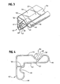
- Figure 7 is a perspective view of a fourth embodiment of an extruded corner post according to the present invention.
- Figure 8 is a top plan view of the corner post of Figure 7 shown installed between a container and a product.
- Figure 9 is a top plan view of a fifth embodiment of a corner post according to the invention, shown installed between a container and a product.
- The invention is a corner post used for protecting packaged products. The corner post is of unitary construction, being made from extruded plastic, and is designed to provide both lateral and axial compression resistance without foldover, that is, without losing its shape. The present invention includes two types of extruded corner posts: tube type and spring-like open profile type.
- The tube type extruded corner post is so-called because the walls of the post form an enclosed cylindrical tube having a substantially hollow interior. However, unlike conventional corner posts made from convolutely wound paper, the extruded corner post of the present invention includes integrally formed extruded plastic ribs extending between the opposing walls of the post. As explained below, these ribs protect the walls of an appliance by directing lateral forces to the relatively stronger structural frame of the appliance.
- Turning to the drawings, there is shown in Figures 1 and 2 an elongated extruded
plastic corner post 10 for protecting a packaged product, such as an appliance. Thecorner post 10 comprises aninner wall 12 and anouter wall 14 connected at theends corner post 10 to form a substantially hollow cylindrical tube. Theouter wall 14 has two substantiallyplanar legs outer apex 24. When thecorner post 10 is installed between a product P and a container C as illustrated in Figure 2, theouter wall 14 is adjacent the inside walls of the container C. - The inner wall also has two substantially
planar legs inner corner 28. When installed, theinner legs inner wall 12 is substantially coextensive with theouter wall 14, meaning the inner wall andouter walls outer walls ends corner post 10 away from theapex 24 andinner corner 28. Preferably, theends walls - Longitudinal webs or
ribs 20 connect the opposing faces of the inner andouter walls vertical ends ribs 20 are perpendicular to the inner andouter walls Perpendicular ribs 20 allows thecorner post 10 to maintain the distance between the container and the product when the container is subjected to lateral forces, thereby preventing the container from collapsing inwardly. - Alternatively, the ribs may be form an oblique angle with respect to the outer and
inner walls - The
ribs 20 may be disposed anywhere along the legs of thecorner post 10. While the illustrated embodiment shows a pair ofribs 20, one disposed within each leg of thecorner post 10, any number of ribs may be incorporated into the design of the extrudedcorner post 10. Preferably the ribs are substantially planar, that is, they have a substantially linear horizontal cross section, as shown in Figures 1 and 2. Such ribs may hereinafter be referred to as "straight" ribs. Alternatively, the ribs may be curved, that is, have an arcuate horizontal cross section, as described below with respect to the embodiment illustrated in Figures 3 and 4. - The corner post of the present invention is formed by an extrusion process in which melted polymer is discharged through a die configured to produce a corner post having the desired cross sectional shape. The inner and outer walls and connecting ribs form a single unitary structure. Plastic extrusion is particular well suited for making corner posts of varying heights. Different cross sectional shapes can be achieved by using different dies. The thickness of the walls and ribs, the distance between the walls and the curvature of the ends may be varied as needed.
- The extruded tube type corner post is particularly useful in protecting appliances having thin metal walls affixed to a rigid structural frame. The appliance frame usually has a structural area located near the top and/or bottom of the vertical profile of the appliance. This area, unlike the relatively weaker sidewalls, can withstand large lateral forces.
- Referring to Fig. 2, when the
extruded corner post 10 is placed between the appliance P and the container C such that a portion of eachrib 20 is adjacent a structural area of theappliance 22, theribs 20 can transfer lateral forces directly to the structural area, thereby protecting the relatively weaker sidewalls from damage. And because the extruded corner post does not collapse, it maintains the distance between the container C and the appliance P, thereby preventing the container C from collapsing inwardly. - The
ribs 20 may extend the full longitudinal height of thecorner post 10 or less than the full height. If the ribs extend less than the full height of the post, it is preferred that they at least extend along that area of thecorner post 10 adjacent the structural area of the appliance so as to be able to transfer outside forces directly to the structural areas of the appliance. - Figures 3 and 4 illustrate a second embodiment of the extruded plastic corner post of the present invention having some additional optional features not shown in the embodiment depicted in Figures 1 and 2. Like the first embodiment, the
corner post 40 comprises substantially L-shaped coextensive inner andouter walls corner post 40 has astraight rib 50 disposed between theends outer walls rib 50 is perpendicular to the inner andouter walls - As shown in Figures 3 and 4, the ribs need not be straight. The
corner post 40 has acurved rib 52 disposed between theends corner post 40 and connecting the inner andouter walls post 40. Curved ribs, because of their shape, are more flexible than straight ribs, and may be used where increased flexibility is desired. - Whether straight or curved, the ribs may extend between substantially flat opposing wall surfaces, between a flat wall surface and an opposing bead, or between two opposing beads. In the embodiment shown in Figures 3 and 4, the
straight rib 50 extends between two substantially flat opposing wall surfaces 42, 44, and thecurved rib 52 extends between a substantiallyflat wall surface 42 and an opposingbead 54. - The
bead 54 is disposed in theouter wall 44 and is directed inwardly toward the hollow interior of thecorner post 40. Thebead 54 is V-shaped and comprises inwardly slanting opposingwalls apex 58. Thebead 54 improves the axial compression characteristics of thecorner post 40. If desired, more than one bead may be formed in theouter wall 42. Alternatively, or in addition to theouter wall bead 54, one or more beads may be disposed in theinner wall 42. The outer and inner wall beads may be V-shaped, U-shaped or any other suitable shape. In this particular embodiment, thecurved rib 52 extends between the flat surface of theinner wall 42 and thejuncture 58, although the curved rib may also extend between opposing flat surfaces. - Returning to Figures 3 and 4, it can be seen that the
corner post 40 may have a bead or cut outportion 60 disposed along theinner wall 42 to surround and protect product components that protrude beyond the plane of the product walls, such as handles, knobs and hinges. The cut outportion 60 may be formed in any suitable shape to accommodate the geometry of the component to be protected. - The spring-like profile extruded corner post is so-called because the walls of the post act in a spring-like fashion to absorb lateral shocks, rather than directing forces to a specific area as with the tube type extruded corner post. The spring-like extruded corner post has an open profile, that is, it does not form an enclosed hollow tube.
- Three embodiments of the spring-like profile embodiment are shown in Figures 5 to 9. Figures 5 and 6 show a first embodiment of a spring-like corner post 70 comprising two
legs inner corner 73. Thefirst leg 72 comprises a substantially planarinner segment 76 extending away from theinner corner 73 and terminating at afirst bend 77, a substantiallyplanar rib 79 extending from the first bend away from thesecond leg 74 to asecond bend 82, and a substantially planarouter segment 78 extending from thesecond bend 82 in a direction away from thesecond leg 74 and along a plane substantially parallel to the plane of theinner segment 76. The substantiallyplanar rib 79 connects the inner andouter segments outer segments - Alternatively, as discussed below with respect to Figure 9, the rib may have a curved horizontal cross section. In such instances the rib may curve outward, away from the container corner c, or inward, toward the corner c.
- The
second leg 74 is similarly configured, having inner andouter segments rib 89. When in use, both inner segments, 76, 86 are adjacent the walls of the product P being protected, and bothouter segments - The
corner post 70 and the container C define a buffer or cushion area A. When lateral force is exerted on the container C, thecorner post 70 flattens somewhat as theouter segments - Figures 7 and 8 illustrate another embodiment of a spring-like extruded corner post 100 similar to that of Figures 5 and 6 except that the
ribs outer segments corner post 70 shown in Figures 7 and 8 comprises twolegs 92, 94 forming a right angle and joined at aninner corner 93. The first leg 92 comprises aninner segment 96 extending along a plane away from theinner corner 93 and terminating at anend 97, a substantiallyplanar rib 99 extending from thefirst bend 97 away from thesecond leg 94 to asecond bend 102, and a substantially planarouter segment 98 extending from thesecond bend 82 in a direction towardsecond leg 96 and along a plane substantially parallel to the plane of theinner segment 96. Therib 99 may be planar as illustrated in Figures 7 and 8 or any suitable shape. Therib 99 forms an obtuse angle with respect to the first leg inner segment 92. The first legouter segment 98 bends back upon therib 99 such that therib 99 and the first legouter segment 98 define an acute angle, preferably one of about 45 degrees. - The
second leg 94 is similarly configured, having inner andouter segments rib 109. When placed inside a container C between a product P and the inside walls of the container C, both inner segments, 96, 106 are adjacent the walls of the product P being protected, and bothouter segments corner post 70 compresses to protect and cushion the product P inside the container C. - Figure 9 illustrates yet another embodiment of a spring-like profile extruded corner post, one having a curved rib. The
corner post 110 has twolegs inner corner 113. Thesecond leg 114 is similar in configuration to thesecond leg 74 of thecorner post 70 illustrated in Figures 5 and 6. That is, it comprises a substantiallyplanar rib 129 connecting substantially planar inner andouter segments - The
first leg 112 comprises a substantially planarinner segment 116 extending away from theinner corner 113 and terminating at afirst bend 117, an outwardlycurved rib 119 extending from thefirst bend 117 to asecond bend 121, and anouter segment 118 extending from thesecond bend 121. Theouter segment 118 comprises first and second substantiallyplanar portions second bend 121 parallel to the first leginner segment 116 such that the firstplanar portion 120 and the first leginner segment 116 substantially opposite each other, and terminates in a right angle bend orapex 122. The secondplanar portion 124 extends from the apex 122 and terminates in afree end 132. The secondplanar portion 124 is coplanar with the second legouter segment 128. - When the extruded
corner post 110 is installed inside a container C around a product P, theinner corner 113 is adjacent a corner of the product P, theinner segments outer segments - Thus there has been described an extruded elongated corner post to be used in the packaging industry to protect products during distribution. The corner post may have a closed tubular shape or an open spring-like shape. With respect to the tube type extruded corner post, the rib shape location can be varied to direct lateral forces imparted during distribution to the strongest area of the product being protected and to enhance column strength, thereby reducing product damage. The enhanced column strength of the tubular type extruded corner post insures that stacked units in warehouses and transportation vehicles remain upright to eliminate leaning stacks that can cause potentially dangerous situations and product damage.
- The open profile spring-like extruded corner post absorbs lateral shock by flattening or compressing, then returning to its original shape. When a lateral force is imparted on the container, the spring-like corner post flattens, temporarily reducing the buffer area between the container and the product. As the lateral force dissipates, the spring-like corner post returns to its original non-compressed state.
- Other modifications and alternative embodiments of the invention are contemplated which do not depart from the spirit and scope of the invention as defined by the foregoing teachings and appended claims. It is intended that the claims cover all such modifications that fall within their scope.
Claims (6)
- An elongated extruded plastic corner post (70) for protecting a packaged product, the corner post (70) comprising two elongated legs (72, 74; 92, 94) joined along an inner corner (73; 93) and forming a substantially right angle at the inner corner juncture, each leg (72, 74; 92, 94) comprising:a substantially planar inner segment (76, 86; 96, 106) extending from the inner corner (73; 93) and terminating at a first bend (77; 97);a substantially planar rib (79, 89; 99, 109) extending from the first bend (77; 97) outwardly to a second bend (82; 102); anda substantially planar outer segment (78, 88; 98, 108) extending from the second bend (82; 102) along a plane substantially parallel to the plane of the inner segment (76, 86; 96, 106);said inner segment (76, 86; 96, 106), rib (79, 89; 99, 109) and outer segment (78, 88; 98, 108) being integrally formed.
- The extruded corner post of claim 1 wherein the rib (79, 89) extends at an obtuse angle from the inner segment (76, 86) and the outer segment (78, 88) extends at an obtuse angle from the rib (79, 89).
- The extruded corner post of claim 1 wherein the rib (99, 109) extends at an obtuse angle from the inner segment (96, 106) and the outer segment (98, 108) extends at an acute angle from the rib (99, 109).
- An elongated extruded plastic corner post (110) for protecting a packaged product, the corner post (110) comprising first and second elongated legs (112, 114) joined along an inner corner (113) and forming a substantially right angle at the inner corner juncture (113), said first leg (112) comprising:a substantially planar inner segment (116) extending from the inner corner (113) and terminating at a first bend (117) ;an outwardly curved rib (119) extending away from the first bend (117) to a second bend (121); andan outer segment, said outer segment comprising a substantially planar first portion (120) extending from the second bend (121) along a plane substantially parallel to the plane of the inner segment (116) and terminating in a right angle bend (122), and a substantially planar second portion (124) extending from the right angle bend (122) and terminating in a free end (132);said inner segment (116), curved rib (119) and outer segment (120, 124) being integrally formed.
- The extruded corner post (110) of claim 4 wherein the second leg (114) comprises:a substantially planar inner segment (126) extending from the inner corner (113) and terminating at a third bend;a substantially planar rib (129) extending from the third bend outwardly to a fourth bend; anda substantially planar outer segment (128) extending from the fourth bend along a plane substantially parallel to the plane of the inner segment (126).
- The extruded corner post of claim 5 wherein the planar rib (129) extends at an obtuse angle from the second leg inner segment (126) and the second leg outer segment (128) extends at an obtuse angle from the planar rib (129).
Applications Claiming Priority (2)
| Application Number | Priority Date | Filing Date | Title |
|---|---|---|---|
| US09/828,369 US6520336B2 (en) | 2001-04-04 | 2001-04-04 | Extruded corner post for vertical and lateral protection |
| EP02707808A EP1385744B1 (en) | 2001-04-04 | 2002-02-12 | Extruded corner post for vertical and lateral protection |
Related Parent Applications (1)
| Application Number | Title | Priority Date | Filing Date |
|---|---|---|---|
| EP02707808A Division EP1385744B1 (en) | 2001-04-04 | 2002-02-12 | Extruded corner post for vertical and lateral protection |
Publications (2)
| Publication Number | Publication Date |
|---|---|
| EP1714909A1 true EP1714909A1 (en) | 2006-10-25 |
| EP1714909B1 EP1714909B1 (en) | 2009-04-15 |
Family
ID=25251610
Family Applications (2)
| Application Number | Title | Priority Date | Filing Date |
|---|---|---|---|
| EP06016173A Expired - Lifetime EP1714909B1 (en) | 2001-04-04 | 2002-02-12 | Extruded plastic corner post |
| EP02707808A Expired - Lifetime EP1385744B1 (en) | 2001-04-04 | 2002-02-12 | Extruded corner post for vertical and lateral protection |
Family Applications After (1)
| Application Number | Title | Priority Date | Filing Date |
|---|---|---|---|
| EP02707808A Expired - Lifetime EP1385744B1 (en) | 2001-04-04 | 2002-02-12 | Extruded corner post for vertical and lateral protection |
Country Status (9)
| Country | Link |
|---|---|
| US (2) | US6520336B2 (en) |
| EP (2) | EP1714909B1 (en) |
| JP (2) | JP3847714B2 (en) |
| AT (2) | ATE428655T1 (en) |
| CA (1) | CA2435473C (en) |
| DE (2) | DE60232034D1 (en) |
| ES (2) | ES2269655T3 (en) |
| MX (1) | MXPA03006627A (en) |
| WO (1) | WO2002081311A2 (en) |
Families Citing this family (52)
| Publication number | Priority date | Publication date | Assignee | Title |
|---|---|---|---|---|
| US7128214B2 (en) * | 2001-12-18 | 2006-10-31 | Sonoco Development, Inc. | Reinforced packaging support post assembly |
| US20040232021A1 (en) * | 2003-05-23 | 2004-11-25 | Linton Loral G. | ATV storage/shipping container |
| US7325500B2 (en) * | 2003-08-08 | 2008-02-05 | Gary Carpenter | Packaging system, apparatus, and method with articulable corner support members |
| US7111734B2 (en) * | 2003-10-15 | 2006-09-26 | Robinson Jr Jack B | Edge protector |
| US7299924B2 (en) * | 2003-10-15 | 2007-11-27 | Robinson Jr Jack B | Edge protector |
| US7264863B2 (en) * | 2003-12-12 | 2007-09-04 | Illinois Tool Works Inc | Cabinet corner protector |
| US7383952B2 (en) * | 2005-04-27 | 2008-06-10 | Illinois Tool Works Inc. | Corner or edge protector exhibiting improved flexural strength and resistance properties |
| US20070151197A1 (en) * | 2005-12-21 | 2007-07-05 | Grand Hall Enterprise Co., Ltd. | Strut for closet frame |
| US20070235344A1 (en) * | 2006-04-06 | 2007-10-11 | Applied Materials, Inc. | Process for high copper removal rate with good planarization and surface finish |
| CN101234690B (en) * | 2007-01-31 | 2011-11-02 | 索诺科开发公司 | Corner post for use with an article having a contoured vertical edge |
| JP4946482B2 (en) * | 2007-02-08 | 2012-06-06 | 船井電機株式会社 | Buffer packaging material and buffer packaging material for TV receiver |
| EP2648994B1 (en) * | 2010-12-07 | 2015-05-13 | Armored (UK) Limited | Improved corner protector |
| KR20130027713A (en) * | 2011-09-08 | 2013-03-18 | 삼성전자주식회사 | Packaging box and fabrication method thereof |
| US8915559B2 (en) | 2011-11-29 | 2014-12-23 | Bsh Home Appliances Corporation | Household appliance including force distributor |
| US9169063B2 (en) * | 2012-05-29 | 2015-10-27 | Sierra Packaging Solutions | Corner boards, container assemblies including the same, and methods of making and using the same |
| USD707231S1 (en) | 2013-05-20 | 2014-06-17 | World Richman Manufacturing Corporation | Case corner bracket with attachment point for retractable elastic for securing a portable electronic device |
| US9511920B2 (en) | 2013-07-09 | 2016-12-06 | T & M Design, Llc | Edge protector |
| USD715633S1 (en) | 2013-11-13 | 2014-10-21 | T & M Design, Llc | Edge protector |
| CN105775382A (en) * | 2014-12-23 | 2016-07-20 | T&M设计公司 | Inclined edge protector |
| US9783333B1 (en) * | 2015-01-27 | 2017-10-10 | Packaging Corporation Of America | Post construction and tiered palletizable container comprising such posts |
| EP3259205B1 (en) * | 2015-02-19 | 2020-05-27 | Abzac Canada Inc. | Corner piece for packaging |
| CA2993487A1 (en) * | 2015-07-27 | 2017-02-02 | Usg Boral Building Products Pty Limited | Angle protector |
| CA2945654C (en) * | 2015-10-20 | 2024-01-09 | Todd Fluery | Angle edge protector having a cover |
| US9669985B1 (en) * | 2015-11-13 | 2017-06-06 | Solarcity Corporation | Photovoltaic module stackable corner protector |
| USD852614S1 (en) * | 2016-08-13 | 2019-07-02 | Ben Schloss | Edge corner guard |
| JP6357218B2 (en) * | 2016-12-28 | 2018-07-11 | 積水化成品工業株式会社 | Packing material and package |
| USD908003S1 (en) | 2017-02-06 | 2021-01-19 | Rational Packaging Llc | Packaging element |
| USD908499S1 (en) | 2017-02-06 | 2021-01-26 | Rational Packaging Llc | Void filling packaging element |
| USD908004S1 (en) | 2017-02-06 | 2021-01-19 | Rational Packaging Llc | Packaging element |
| US10899524B1 (en) | 2017-02-06 | 2021-01-26 | Rational Packaging Llc | Self-locating structural packaging element |
| USD989624S1 (en) * | 2017-02-06 | 2023-06-20 | Rational Packaging Llc | Hourglass shaped packaging element |
| USD908007S1 (en) * | 2017-02-06 | 2021-01-19 | Rational Packaging Llc | Gap filling packaging element |
| USD1010445S1 (en) | 2018-04-27 | 2024-01-09 | Rational Packaging Llc | Combined scalloped brace and wave post |
| USD908005S1 (en) | 2017-02-06 | 2021-01-19 | Rational Packaging Llc | Trilobular packaging element |
| US11104501B1 (en) | 2018-04-27 | 2021-08-31 | Rational Packaging Llc | Void filling structural packaging element |
| USD1011190S1 (en) | 2018-04-27 | 2024-01-16 | Rational Packaging Llc | Scalloped wave post |
| WO2019099035A1 (en) * | 2017-11-17 | 2019-05-23 | Hewlett-Packard Development Company, L.P. | Protective packaging |
| US10913589B2 (en) * | 2018-01-05 | 2021-02-09 | Tower Ipco Company Limited | Compression resistant package for wall and ceiling tile |
| CN111439482A (en) * | 2019-01-16 | 2020-07-24 | 海信视像科技股份有限公司 | Cushion and packaging structure |
| US11208253B1 (en) | 2020-07-07 | 2021-12-28 | Rational Packaging Llc | Packaging assembly with support insert |
| US11505393B1 (en) * | 2020-07-07 | 2022-11-22 | Rational Packaging Llc | Packaging assembly with multi-slit support insert |
| CN112797443B (en) * | 2020-12-30 | 2023-09-26 | 嵊州市卡梦帝电器有限公司 | Packaging frame for steaming and baking integrated kitchen range and welding method thereof |
| USD984896S1 (en) * | 2021-04-07 | 2023-05-02 | Carga Segura, S. de R.L. MI | Support post for packaging system |
| US11667452B2 (en) | 2021-08-25 | 2023-06-06 | Jack B. Robinson, Jr. | Edge protector |
| KR20240010606A (en) * | 2022-07-14 | 2024-01-24 | 삼성디스플레이 주식회사 | Tray for display panel |
| USD1030469S1 (en) * | 2022-09-07 | 2024-06-11 | Cuilan Li | Edge protector strip |
| US12054321B2 (en) | 2022-09-16 | 2024-08-06 | Sonoco Development, Inc. | Protective insert for basiloid package |
| US12037179B2 (en) | 2022-10-12 | 2024-07-16 | Sonoco Development, Inc. | Notched corner post for appliance packaging |
| CN116153193B (en) * | 2022-12-05 | 2025-10-28 | 深圳市光祥科技股份有限公司 | Display screen corner protection device and display screen assembly |
| USD1111194S1 (en) | 2024-01-02 | 2026-02-03 | Rational Packaging Llc | Foldable corner post |
| USD1106819S1 (en) | 2024-07-10 | 2025-12-23 | Steven L. Morey | Foldable corrugated corner element |
| USD1106078S1 (en) | 2024-07-10 | 2025-12-16 | Steven L. Morey | Foldable wave fold back corner |
Citations (5)
| Publication number | Priority date | Publication date | Assignee | Title |
|---|---|---|---|---|
| US4202449A (en) * | 1977-02-24 | 1980-05-13 | Anders Bendt | Protecting device for edges |
| US4244471A (en) * | 1979-04-09 | 1981-01-13 | Whirlpool Corporation | Packaging system |
| JPH04294763A (en) * | 1991-03-15 | 1992-10-19 | Showa Prod Kk | Shock absorber for packing |
| US5918800A (en) * | 1997-07-11 | 1999-07-06 | Illinois Tool Works Inc. | Corner post/edge protector having improved column compressive strength-shaped board |
| US6059104A (en) * | 1999-03-04 | 2000-05-09 | Sonoco Products Company | Corner support post |
Family Cites Families (26)
| Publication number | Priority date | Publication date | Assignee | Title |
|---|---|---|---|---|
| US266577A (en) * | 1882-10-24 | Packing cans | ||
| US1875497A (en) * | 1932-09-06 | Containkb | ||
| US2733851A (en) * | 1956-02-07 | Van ness | ||
| US987958A (en) * | 1909-04-23 | 1911-03-28 | Sefton Mfg Company | Packing or shipping box. |
| US974871A (en) * | 1909-04-28 | 1910-11-08 | Sefton Mfg Company | Packing or shipping box. |
| US1786189A (en) * | 1928-11-15 | 1930-12-23 | Rochester Folding Box Company | Corner-cushion-pad packing device |
| US2376530A (en) * | 1944-02-24 | 1945-05-22 | Jack & Heintz Inc | Receptacle |
| US3086689A (en) * | 1961-02-20 | 1963-04-23 | Vanant Company Inc | Support and suspension member for articles packed in cartons |
| US3129868A (en) * | 1961-04-03 | 1964-04-21 | Mead Corp | Corner post construction |
| US3029994A (en) * | 1961-04-06 | 1962-04-17 | Gen Electric | Top lifting fiber-board shipping crate |
| US3244347A (en) * | 1964-02-20 | 1966-04-05 | Mead Corp | Corner post construction |
| US3648920A (en) * | 1968-11-20 | 1972-03-14 | Clevepak Corp | Tubular member |
| US3935357A (en) | 1973-03-27 | 1976-01-27 | I. S. A. P. S.P.A. | Hollow extruded plastic strips for packings |
| US4248350A (en) * | 1979-10-22 | 1981-02-03 | Westvaco Corporation | Corner post with integral lock |
| US4483444A (en) | 1982-04-22 | 1984-11-20 | Clevepost, Inc. | Packaging system and corner post therefor |
| US4482054A (en) * | 1982-04-22 | 1984-11-13 | Clevepost, Inc. | Support and cushioning tube |
| DE3718545A1 (en) * | 1987-06-03 | 1988-12-22 | Signode System Gmbh | EDGE PROTECTION PROFILE SECTION AND METHOD FOR PRODUCING THE SAME |
| US5149575A (en) * | 1990-10-17 | 1992-09-22 | Soifer Martin T | Corner edge bumpers |
| US5267651A (en) | 1992-04-15 | 1993-12-07 | Hughes Billy R | Support post for packaging system |
| US5304412A (en) * | 1992-11-17 | 1994-04-19 | Eli Plastics Industrial Co., Ltd. | Extruded plastic article with a decorative plastic strip |
| DE29509037U1 (en) * | 1995-05-31 | 1995-09-14 | Tempel, Fritz, 66976 Rodalben | Side edge protection |
| US5593039A (en) | 1995-11-22 | 1997-01-14 | Sonoco Products Compnay | Corner post for packaging system |
| US6186329B1 (en) * | 1999-08-27 | 2001-02-13 | Sonoco Development, Inc. | Multiple-grade paper corner post |
| US6286683B1 (en) * | 1999-08-27 | 2001-09-11 | The United States Of America As Represented By The Secretary Of Argriculture | Multiple-piece corner post |
| US6234314B1 (en) * | 1999-08-30 | 2001-05-22 | Sonoco Development, Inc. | Package support post with joined surfaces |
| US6247596B1 (en) * | 2000-02-11 | 2001-06-19 | Sonoco Development, Inc. | Spring loaded corner post for use with plastic film wrapping |
-
2001
- 2001-04-04 US US09/828,369 patent/US6520336B2/en not_active Expired - Lifetime
-
2002
- 2002-02-12 DE DE60232034T patent/DE60232034D1/en not_active Expired - Lifetime
- 2002-02-12 ES ES02707808T patent/ES2269655T3/en not_active Expired - Lifetime
- 2002-02-12 AT AT06016173T patent/ATE428655T1/en not_active IP Right Cessation
- 2002-02-12 DE DE60213781T patent/DE60213781T2/en not_active Expired - Lifetime
- 2002-02-12 ES ES06016173T patent/ES2325791T3/en not_active Expired - Lifetime
- 2002-02-12 JP JP2002579313A patent/JP3847714B2/en not_active Expired - Fee Related
- 2002-02-12 AT AT02707808T patent/ATE335672T1/en not_active IP Right Cessation
- 2002-02-12 WO PCT/US2002/004766 patent/WO2002081311A2/en not_active Ceased
- 2002-02-12 MX MXPA03006627A patent/MXPA03006627A/en active IP Right Grant
- 2002-02-12 CA CA002435473A patent/CA2435473C/en not_active Expired - Fee Related
- 2002-02-12 EP EP06016173A patent/EP1714909B1/en not_active Expired - Lifetime
- 2002-02-12 EP EP02707808A patent/EP1385744B1/en not_active Expired - Lifetime
- 2002-11-27 US US10/065,896 patent/US6595367B2/en not_active Expired - Lifetime
-
2006
- 2006-07-03 JP JP2006182913A patent/JP2006298497A/en active Pending
Patent Citations (5)
| Publication number | Priority date | Publication date | Assignee | Title |
|---|---|---|---|---|
| US4202449A (en) * | 1977-02-24 | 1980-05-13 | Anders Bendt | Protecting device for edges |
| US4244471A (en) * | 1979-04-09 | 1981-01-13 | Whirlpool Corporation | Packaging system |
| JPH04294763A (en) * | 1991-03-15 | 1992-10-19 | Showa Prod Kk | Shock absorber for packing |
| US5918800A (en) * | 1997-07-11 | 1999-07-06 | Illinois Tool Works Inc. | Corner post/edge protector having improved column compressive strength-shaped board |
| US6059104A (en) * | 1999-03-04 | 2000-05-09 | Sonoco Products Company | Corner support post |
Non-Patent Citations (1)
| Title |
|---|
| PATENT ABSTRACTS OF JAPAN vol. 017, no. 103 (M - 1374) 2 March 1993 (1993-03-02) * |
Also Published As
| Publication number | Publication date |
|---|---|
| MXPA03006627A (en) | 2004-04-21 |
| ES2325791T3 (en) | 2009-09-17 |
| EP1385744A2 (en) | 2004-02-04 |
| JP3847714B2 (en) | 2006-11-22 |
| US6595367B2 (en) | 2003-07-22 |
| ATE335672T1 (en) | 2006-09-15 |
| CA2435473A1 (en) | 2002-10-17 |
| EP1714909B1 (en) | 2009-04-15 |
| JP2004524235A (en) | 2004-08-12 |
| WO2002081311A2 (en) | 2002-10-17 |
| US20030052037A1 (en) | 2003-03-20 |
| DE60232034D1 (en) | 2009-05-28 |
| EP1385744B1 (en) | 2006-08-09 |
| ES2269655T3 (en) | 2007-04-01 |
| ATE428655T1 (en) | 2009-05-15 |
| CA2435473C (en) | 2006-08-01 |
| US6520336B2 (en) | 2003-02-18 |
| JP2006298497A (en) | 2006-11-02 |
| WO2002081311A3 (en) | 2002-11-21 |
| US20020144923A1 (en) | 2002-10-10 |
| DE60213781D1 (en) | 2006-09-21 |
| DE60213781T2 (en) | 2007-08-23 |
Similar Documents
| Publication | Publication Date | Title |
|---|---|---|
| US6520336B2 (en) | Extruded corner post for vertical and lateral protection | |
| CA2466455C (en) | Reinforced packaging support post assembly | |
| EP1284910B1 (en) | Spring loaded corner post for use with plastic film wrapping | |
| US5131541A (en) | Corner post and packaging system | |
| JPH0648469A (en) | Supporting post | |
| EP1214256B1 (en) | Shock absorbing support post for package | |
| US3244347A (en) | Corner post construction | |
| US4482054A (en) | Support and cushioning tube | |
| US6059104A (en) | Corner support post | |
| US8163370B2 (en) | Buffer device providing reliable buffer effect | |
| US8584858B2 (en) | Packing reinforcement member | |
| US20040195242A1 (en) | Pallet container | |
| US11319134B2 (en) | Product packaging system | |
| US20090071861A1 (en) | Foam Buffer Device for Packaging | |
| EP1459991A1 (en) | Synthetic resin container | |
| US7025223B2 (en) | Grid casing for a container | |
| US20170082238A1 (en) | Appliance Shipping Runner | |
| JP3227014B2 (en) | Plastic bottle | |
| US20220185535A1 (en) | Folding container | |
| JPH10218237A (en) | Box with function to prevent barrel expansion | |
| CN101454214A (en) | Base for a packaging made from plastic | |
| JP2005047552A (en) | Packaging equipment | |
| JPS6131958Y2 (en) | ||
| JPS6020611Y2 (en) | Cushioning material for packaging | |
| JPH06247469A (en) | Packaging device |
Legal Events
| Date | Code | Title | Description |
|---|---|---|---|
| PUAI | Public reference made under article 153(3) epc to a published international application that has entered the european phase |
Free format text: ORIGINAL CODE: 0009012 |
|
| AC | Divisional application: reference to earlier application |
Ref document number: 1385744 Country of ref document: EP Kind code of ref document: P |
|
| AK | Designated contracting states |
Kind code of ref document: A1 Designated state(s): AT BE CH CY DE DK ES FI FR GB GR IE IT LI LU MC NL PT SE TR |
|
| 17P | Request for examination filed |
Effective date: 20070425 |
|
| AKX | Designation fees paid |
Designated state(s): AT BE CH CY DE DK ES FI FR GB GR IE IT LI LU MC NL PT SE TR |
|
| 17Q | First examination report despatched |
Effective date: 20070706 |
|
| GRAP | Despatch of communication of intention to grant a patent |
Free format text: ORIGINAL CODE: EPIDOSNIGR1 |
|
| RIN1 | Information on inventor provided before grant (corrected) |
Inventor name: BAECHLE, JAMES |
|
| GRAS | Grant fee paid |
Free format text: ORIGINAL CODE: EPIDOSNIGR3 |
|
| GRAA | (expected) grant |
Free format text: ORIGINAL CODE: 0009210 |
|
| AC | Divisional application: reference to earlier application |
Ref document number: 1385744 Country of ref document: EP Kind code of ref document: P |
|
| AK | Designated contracting states |
Kind code of ref document: B1 Designated state(s): AT BE CH CY DE DK ES FI FR GB GR IE IT LI LU MC NL PT SE TR |
|
| REG | Reference to a national code |
Ref country code: CH Ref legal event code: EP Ref country code: GB Ref legal event code: FG4D |
|
| REG | Reference to a national code |
Ref country code: IE Ref legal event code: FG4D |
|
| REF | Corresponds to: |
Ref document number: 60232034 Country of ref document: DE Date of ref document: 20090528 Kind code of ref document: P |
|
| REG | Reference to a national code |
Ref country code: SE Ref legal event code: TRGR |
|
| REG | Reference to a national code |
Ref country code: ES Ref legal event code: FG2A Ref document number: 2325791 Country of ref document: ES Kind code of ref document: T3 |
|
| PG25 | Lapsed in a contracting state [announced via postgrant information from national office to epo] |
Ref country code: FI Free format text: LAPSE BECAUSE OF FAILURE TO SUBMIT A TRANSLATION OF THE DESCRIPTION OR TO PAY THE FEE WITHIN THE PRESCRIBED TIME-LIMIT Effective date: 20090415 Ref country code: AT Free format text: LAPSE BECAUSE OF FAILURE TO SUBMIT A TRANSLATION OF THE DESCRIPTION OR TO PAY THE FEE WITHIN THE PRESCRIBED TIME-LIMIT Effective date: 20090415 Ref country code: PT Free format text: LAPSE BECAUSE OF FAILURE TO SUBMIT A TRANSLATION OF THE DESCRIPTION OR TO PAY THE FEE WITHIN THE PRESCRIBED TIME-LIMIT Effective date: 20090915 |
|
| PG25 | Lapsed in a contracting state [announced via postgrant information from national office to epo] |
Ref country code: DK Free format text: LAPSE BECAUSE OF FAILURE TO SUBMIT A TRANSLATION OF THE DESCRIPTION OR TO PAY THE FEE WITHIN THE PRESCRIBED TIME-LIMIT Effective date: 20090415 |
|
| PLBE | No opposition filed within time limit |
Free format text: ORIGINAL CODE: 0009261 |
|
| STAA | Information on the status of an ep patent application or granted ep patent |
Free format text: STATUS: NO OPPOSITION FILED WITHIN TIME LIMIT |
|
| 26N | No opposition filed |
Effective date: 20100118 |
|
| BERE | Be: lapsed |
Owner name: SONOCO DEVELOPMENT, INC. Effective date: 20100228 |
|
| REG | Reference to a national code |
Ref country code: NL Ref legal event code: V1 Effective date: 20100901 |
|
| REG | Reference to a national code |
Ref country code: CH Ref legal event code: PL |
|
| PG25 | Lapsed in a contracting state [announced via postgrant information from national office to epo] |
Ref country code: GR Free format text: LAPSE BECAUSE OF FAILURE TO SUBMIT A TRANSLATION OF THE DESCRIPTION OR TO PAY THE FEE WITHIN THE PRESCRIBED TIME-LIMIT Effective date: 20090716 Ref country code: CH Free format text: LAPSE BECAUSE OF NON-PAYMENT OF DUE FEES Effective date: 20100228 Ref country code: MC Free format text: LAPSE BECAUSE OF NON-PAYMENT OF DUE FEES Effective date: 20100301 Ref country code: LI Free format text: LAPSE BECAUSE OF NON-PAYMENT OF DUE FEES Effective date: 20100228 |
|
| REG | Reference to a national code |
Ref country code: FR Ref legal event code: ST Effective date: 20101029 |
|
| PGFP | Annual fee paid to national office [announced via postgrant information from national office to epo] |
Ref country code: SE Payment date: 20100806 Year of fee payment: 9 |
|
| PG25 | Lapsed in a contracting state [announced via postgrant information from national office to epo] |
Ref country code: FR Free format text: LAPSE BECAUSE OF NON-PAYMENT OF DUE FEES Effective date: 20100301 Ref country code: NL Free format text: LAPSE BECAUSE OF NON-PAYMENT OF DUE FEES Effective date: 20100901 Ref country code: IE Free format text: LAPSE BECAUSE OF NON-PAYMENT OF DUE FEES Effective date: 20100212 |
|
| PG25 | Lapsed in a contracting state [announced via postgrant information from national office to epo] |
Ref country code: BE Free format text: LAPSE BECAUSE OF NON-PAYMENT OF DUE FEES Effective date: 20100228 |
|
| REG | Reference to a national code |
Ref country code: ES Ref legal event code: FD2A Effective date: 20110325 |
|
| PG25 | Lapsed in a contracting state [announced via postgrant information from national office to epo] |
Ref country code: IT Free format text: LAPSE BECAUSE OF NON-PAYMENT OF DUE FEES Effective date: 20100212 |
|
| PG25 | Lapsed in a contracting state [announced via postgrant information from national office to epo] |
Ref country code: ES Free format text: LAPSE BECAUSE OF NON-PAYMENT OF DUE FEES Effective date: 20110314 |
|
| PGFP | Annual fee paid to national office [announced via postgrant information from national office to epo] |
Ref country code: IT Payment date: 20100812 Year of fee payment: 9 |
|
| PGRI | Patent reinstated in contracting state [announced from national office to epo] |
Ref country code: IT Effective date: 20110616 |
|
| PG25 | Lapsed in a contracting state [announced via postgrant information from national office to epo] |
Ref country code: ES Free format text: LAPSE BECAUSE OF NON-PAYMENT OF DUE FEES Effective date: 20100213 |
|
| REG | Reference to a national code |
Ref country code: SE Ref legal event code: EUG |
|
| PGRI | Patent reinstated in contracting state [announced from national office to epo] |
Ref country code: IT Effective date: 20110616 |
|
| PG25 | Lapsed in a contracting state [announced via postgrant information from national office to epo] |
Ref country code: CY Free format text: LAPSE BECAUSE OF FAILURE TO SUBMIT A TRANSLATION OF THE DESCRIPTION OR TO PAY THE FEE WITHIN THE PRESCRIBED TIME-LIMIT Effective date: 20090415 |
|
| PG25 | Lapsed in a contracting state [announced via postgrant information from national office to epo] |
Ref country code: LU Free format text: LAPSE BECAUSE OF NON-PAYMENT OF DUE FEES Effective date: 20100212 |
|
| PG25 | Lapsed in a contracting state [announced via postgrant information from national office to epo] |
Ref country code: SE Free format text: LAPSE BECAUSE OF NON-PAYMENT OF DUE FEES Effective date: 20110213 |
|
| PGFP | Annual fee paid to national office [announced via postgrant information from national office to epo] |
Ref country code: TR Payment date: 20140121 Year of fee payment: 13 |
|
| PGFP | Annual fee paid to national office [announced via postgrant information from national office to epo] |
Ref country code: GB Payment date: 20140212 Year of fee payment: 13 |
|
| PGFP | Annual fee paid to national office [announced via postgrant information from national office to epo] |
Ref country code: DE Payment date: 20140417 Year of fee payment: 13 |
|
| REG | Reference to a national code |
Ref country code: DE Ref legal event code: R119 Ref document number: 60232034 Country of ref document: DE |
|
| GBPC | Gb: european patent ceased through non-payment of renewal fee |
Effective date: 20150212 |
|
| PG25 | Lapsed in a contracting state [announced via postgrant information from national office to epo] |
Ref country code: GB Free format text: LAPSE BECAUSE OF NON-PAYMENT OF DUE FEES Effective date: 20150212 Ref country code: DE Free format text: LAPSE BECAUSE OF NON-PAYMENT OF DUE FEES Effective date: 20150901 |
|
| PG25 | Lapsed in a contracting state [announced via postgrant information from national office to epo] |
Ref country code: TR Free format text: LAPSE BECAUSE OF NON-PAYMENT OF DUE FEES Effective date: 20150212 |