EP1714767A2 - Method of making foamed polymer articles of liquid silicon rubber - Google Patents
Method of making foamed polymer articles of liquid silicon rubber Download PDFInfo
- Publication number
- EP1714767A2 EP1714767A2 EP06405123A EP06405123A EP1714767A2 EP 1714767 A2 EP1714767 A2 EP 1714767A2 EP 06405123 A EP06405123 A EP 06405123A EP 06405123 A EP06405123 A EP 06405123A EP 1714767 A2 EP1714767 A2 EP 1714767A2
- Authority
- EP
- European Patent Office
- Prior art keywords
- foamed
- lsr
- molding
- polymer
- use according
- Prior art date
- Legal status (The legal status is an assumption and is not a legal conclusion. Google has not performed a legal analysis and makes no representation as to the accuracy of the status listed.)
- Granted
Links
Images
Classifications
-
- B—PERFORMING OPERATIONS; TRANSPORTING
- B29—WORKING OF PLASTICS; WORKING OF SUBSTANCES IN A PLASTIC STATE IN GENERAL
- B29C—SHAPING OR JOINING OF PLASTICS; SHAPING OF MATERIAL IN A PLASTIC STATE, NOT OTHERWISE PROVIDED FOR; AFTER-TREATMENT OF THE SHAPED PRODUCTS, e.g. REPAIRING
- B29C44/00—Shaping by internal pressure generated in the material, e.g. swelling or foaming ; Producing porous or cellular expanded plastics articles
- B29C44/34—Auxiliary operations
- B29C44/3442—Mixing, kneading or conveying the foamable material
- B29C44/3446—Feeding the blowing agent
-
- B—PERFORMING OPERATIONS; TRANSPORTING
- B29—WORKING OF PLASTICS; WORKING OF SUBSTANCES IN A PLASTIC STATE IN GENERAL
- B29C—SHAPING OR JOINING OF PLASTICS; SHAPING OF MATERIAL IN A PLASTIC STATE, NOT OTHERWISE PROVIDED FOR; AFTER-TREATMENT OF THE SHAPED PRODUCTS, e.g. REPAIRING
- B29C44/00—Shaping by internal pressure generated in the material, e.g. swelling or foaming ; Producing porous or cellular expanded plastics articles
- B29C44/02—Shaping by internal pressure generated in the material, e.g. swelling or foaming ; Producing porous or cellular expanded plastics articles for articles of definite length, i.e. discrete articles
- B29C44/04—Shaping by internal pressure generated in the material, e.g. swelling or foaming ; Producing porous or cellular expanded plastics articles for articles of definite length, i.e. discrete articles consisting of at least two parts of chemically or physically different materials, e.g. having different densities
-
- B—PERFORMING OPERATIONS; TRANSPORTING
- B29—WORKING OF PLASTICS; WORKING OF SUBSTANCES IN A PLASTIC STATE IN GENERAL
- B29C—SHAPING OR JOINING OF PLASTICS; SHAPING OF MATERIAL IN A PLASTIC STATE, NOT OTHERWISE PROVIDED FOR; AFTER-TREATMENT OF THE SHAPED PRODUCTS, e.g. REPAIRING
- B29C44/00—Shaping by internal pressure generated in the material, e.g. swelling or foaming ; Producing porous or cellular expanded plastics articles
- B29C44/02—Shaping by internal pressure generated in the material, e.g. swelling or foaming ; Producing porous or cellular expanded plastics articles for articles of definite length, i.e. discrete articles
- B29C44/12—Incorporating or moulding on preformed parts, e.g. inserts or reinforcements
- B29C44/14—Incorporating or moulding on preformed parts, e.g. inserts or reinforcements the preformed part being a lining
- B29C44/16—Incorporating or moulding on preformed parts, e.g. inserts or reinforcements the preformed part being a lining shaped by the expansion of the material
-
- C—CHEMISTRY; METALLURGY
- C08—ORGANIC MACROMOLECULAR COMPOUNDS; THEIR PREPARATION OR CHEMICAL WORKING-UP; COMPOSITIONS BASED THEREON
- C08G—MACROMOLECULAR COMPOUNDS OBTAINED OTHERWISE THAN BY REACTIONS ONLY INVOLVING UNSATURATED CARBON-TO-CARBON BONDS
- C08G77/00—Macromolecular compounds obtained by reactions forming a linkage containing silicon with or without sulfur, nitrogen, oxygen or carbon in the main chain of the macromolecule
- C08G77/04—Polysiloxanes
- C08G77/06—Preparatory processes
-
- C—CHEMISTRY; METALLURGY
- C08—ORGANIC MACROMOLECULAR COMPOUNDS; THEIR PREPARATION OR CHEMICAL WORKING-UP; COMPOSITIONS BASED THEREON
- C08J—WORKING-UP; GENERAL PROCESSES OF COMPOUNDING; AFTER-TREATMENT NOT COVERED BY SUBCLASSES C08B, C08C, C08F, C08G or C08H
- C08J9/00—Working-up of macromolecular substances to porous or cellular articles or materials; After-treatment thereof
- C08J9/02—Working-up of macromolecular substances to porous or cellular articles or materials; After-treatment thereof using blowing gases generated by the reacting monomers or modifying agents during the preparation or modification of macromolecules
Definitions
- the invention relates to applications of a process for producing foamed polymer moldings from liquid silicone rubber.
- LSR Liquid Silicon Rubber
- LSR is a two-component polymer system whose components are individually unreactive and which offers the trade with specifiable set properties.
- the LSR components are pasty masses. They are combined by means of special pumping, metering and mixing technology to form a molding material which can be processed on an injection molding machine into polymer moldings.
- LSR is a silicone rubber which crosslinks at elevated temperature (at around 150-200 ° C.), namely a so-called "high-temperature crosslinking silicone rubber” (HTV silicone rubber).
- the crosslinking reaction of the polymer is, for example, a platinum-catalyzed addition crosslinking in which a polysiloxane reacts with a crosslinker (consisting of short polymer chains) and under the influence of a Pt catalyst.
- the crosslinker and the catalyst are partial means for carrying out the crosslinking reaction which form two components of a crosslinking agent.
- LSR Compared with conventional cross-linking rubbers (synthetic or natural), LSR is characterized by a high temperature resistance as well as a good physiological compatibility, which results in a safety in terms of hygienic requirements.
- the media resistance of LSR is generally satisfactory; however, it is often worse than solid rubbers, for example when LSR comes into contact with gasoline, fats, oils or aromatics.
- LSR is a very shear and residence time sensitive material. Therefore, in known injection molding screw conveyors are used, which only transport and do not homogenize or mix. In known methods for foam injection molding of thermoplastics (see eg EP-B-0952908 ), the propellant is dosed selectively at one or more holes in the injection unit. It has to be mixed intensively. Applying this procedure analogously to LSR processing, intensive mixing results in shears that induce premature crosslinking in stagnant zones. The process comes to a standstill. Attempts to apply the known method in the LSR analog, therefore, have not led to success.
- a batchwise pre-loading of the LSR components with a physical blowing agent is already known (see EP-A-0 593 863 ).
- This process is not suitable for use as a partial process in combination with the injection molding process.
- Injection molding is carried out quasi-continuously and thus largely or essentially continuously (the prepared molding compound being injected intermittently into the shaping tool, for example in cycles of 20 s).
- the batchwise Procedure would be the combination of procedures possible, but associated with a great effort: It would take a lot of time (according to EP-A-0 593 863 at least 2 hours) and correspondingly large container volumes required.
- the batchwise pre-loading is therefore not economical and therefore not feasible industrially.
- foaming LSR would bring economic benefits.
- the material properties of LSR depend in part on the choice of raw materials. However, a property spectrum of LSR can only be adjusted to a limited extent from the raw material side. By foaming, new material properties can be created with which new fields of application can be opened up. Furthermore, the foaming allows a more efficient utilization of raw materials. Components become lighter, a material use more economical.
- This process for producing a foamed polymer body from the molding composition LSR is substantially continuous (i.e., quasi-continuous).
- the specially prepared, namely with physical blowing agent impregnated molding compound is injected into a molding tool. There, the crosslinking reaction and the formation of foam bubbles take place simultaneously at elevated temperature.
- this Prior to preparation of the molding material, this is in the form of two separately held components, each containing partial means for carrying out the crosslinking reaction and which differ by these partial means.
- the two components are conveyed separately at the beginning of the preparation in two streams under increased pressure. In this case, at least one of the components is impregnated with the physical blowing agent.
- the two streams are combined after impregnation - still under elevated pressure - and mixed. Finally, the reactive mixture formed during mixing is metered and injected while lowering the pressure in a cavity of the forming tool.
- the object of the invention is to use this further developed and an inventive method to provide useful polymer moldings of foamed LSR.
- foamed polymer moldings can be produced by means of the application defined in claim 1.
- the method itself is the subject of the cited, non-prepublished application ( EP 4405329 ).
- the use of the process produces a polymer molded part of LSR having a foaming degree of from 5 to 70% by volume and / or having a Shore A hardness reduced by at least 10% with respect to a non-foamed LSR polymer molded article.
- the produced polymer molding forms a body which interacts with a living object or with another inanimate object and is purposely designed with respect to its physical properties.
- the dependent claims 2 to 10 relate to advantageous embodiments of the polymer moldings produced according to the invention.
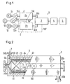
- FIG. 1 A plant 1, with which the method to be used can be carried out, is shown in Fig. 1 as a block diagram.
- Reservoirs 11 and 12 for the molding compound components A and B are connected via pumps 11a, 12a to impregnating means 2a and 2b, respectively. (Only one impregnation device can be provided.)
- An embodiment 2 for the impregnation devices 2a, 2b will be described with reference to FIG.
- the devices 2a, 2b and a mixing device 3 can be produced according to the task to be created polymer body or polymer moldings.
- the foaming takes place in a forming tool 5 simultaneously with the crosslinking reaction.
- the two components A and B are impregnated with a physical blowing fluid C, which with a pump 13a (or compressor) from a reservoir 13 through a line 132 'and inlet nozzle 132 into the impregnation means 2a, 2b is fed.
- a physical blowing fluid C CO 2 , N 2
- a hydrocarbon compound eg pentane
- a mixture of said gases can be used.
- connection device 4 which - not shown - comprises a metering device and a throttle nozzle.
- the throttle nozzle opens into the cavity of the forming tool. 5
- the impregnation device 2 comprises the following components: a housing 20 to a cylindrical mixing chamber 21, are arranged within the static mixer elements 22, and connecting pieces 20a, 20b for the mass to be impregnated; also a tubular wall 23 (or sleeve 23) between housing 20 and mixing chamber 21, which is made of a porous material (for example, sintered metal grains).
- a housing 20 to a cylindrical mixing chamber 21 are arranged within the static mixer elements 22, and connecting pieces 20a, 20b for the mass to be impregnated; also a tubular wall 23 (or sleeve 23) between housing 20 and mixing chamber 21, which is made of a porous material (for example, sintered metal grains).
- the driving fluid C which is fed through the nozzle 132, flows through an annular gap 24 tangentially and axially over the outer surface of the tubular wall 23rd
- a channel system 6 for a coolant is integrated in the housing 20 (indicated by arrows 7, 7 '), with which heat can be dissipated during impregnation from the molding compound components A or B processed by the mixer elements 22.
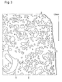
- FIG. 3 shows a drawing which is made after a microscopic image.
- the image forms a section through a sample of foamed LSR and shows micropores 8 and macropores 9.
- the sectional area shown is one to two square millimeters in size.
- the micropores 8 only the outlines are drawn. In the original image you can see different shades within the outline - according to the position of the cutting plane in relation to the position of the pores: dark shading in deep pores, bright in flat pores.
- macropores 9 inner ear-like topographies are also indicated.
- FIG. 3 shows an edge part at a corner of the sample. In an interior region of the sample, the density of macropores 9 increases.
- Microcells are cells - called pores above - with a diameter smaller than about 0.1 mm; a foam with a microcellular structure is a foam with cells whose average diameter (cell size) is less than 0.1 mm.
- Hardness measurements were made on the samples shown as well as on other samples of the same geometry. Reductions in hardness have been measured, which are between 22 and 65% depending on the set foaming degree. The foaming degree can be specified as a density reduction. This is about 50% for the sample shown.
- the polymer molding is for example a handle for a sports or work equipment.
- Haptic properties of the foamed LSR convey a sense of touch that stimulates the sense of touch.
- Such a pleasant grip feeling is for example a "soft touch”.
- the friction properties of the grip surface are modifiable so that they provide a secure grip for an accessing hand.
- Another embodiment is a medical prosthesis or a medical implant.
- Lighter and softer implants as well as pads or savers with new properties are possible: better cushioning, less impairment of surrounding (wound) tissue.
- a breast implant can be produced, wherein due to adapted density, compliance and damping properties of the foamed LSR, a good compatibility of the prosthesis with surrounding body tissue can be established.
- the polymer molding may be an infant or infant nipple or bottle nipple. Due to the adapted density, resilience and damping properties of the foamed LSR, this article makes a natural biting feeling for the baby come alive. In addition to such new material properties that affect the hardness, there is also a use of materials that is more economical.
- the polymer molding may also be designed as a vessel for household use. Such a vessel is in particular a baking pan or a freezer for producing ice cubes, in which the thermal properties are improved. Again, there is a more economical use of materials.
- the freshly prepared polymer molding still contains interfering monomers or other unreacted components. By means of tempering the interfering components can be eliminated. Due to more favorable diffusion conditions in the foamed LSR, the annealing time is shortened.
- a further example of a polymer molding according to the invention is a damping body which is suitable for vibration damping in a noise-generating object (eg car) or in a vibrating object (eg fan).
- a noise-generating object eg car
- a vibrating object eg fan
- the polymer moldings may also be formed in molds suitable for sealing purposes or to compensate for manufacturing tolerances suitable. Enlarged softness makes new sealing concepts possible in which better deformability can be used.
- the polymer molding can also be designed for a pressure roller as a tubular coating or a coating, so as to produce a special printing surface, which allows, for example, with a lower material use improved friction properties.
- the polymer can be used in the form of a composite, in particular a nanocomposite, to which electrically conductive additives have been added.
- a polymer molding with metallic additives can be used as a shield against electromagnetic waves. It is possible to reduce the metal content in comparison with known shields.
- Metallic additives can also increase the electrical conductivity of the molded part in order to prevent electrostatic charging.
- Areas of application of said conductive composites are, for example: antistatic finishing of plastics, antistatic packaging, electromagnetic shielding, heat dissipation in microelectronics, reduction of surface resistances for safety reasons, for example for electrical equipment in the Ex area.
Abstract
Description
Die Erfindung betrifft Anwendungen eines Verfahrens zum Herstellen von geschäumten Polymerformteilen aus Flüssigsilikon-Kautschuk. Die für dieses Polymer gebräuchliche Bezeichnung LSR ("Liquid Silicon Rubber") wird im Folgenden verwendet.The invention relates to applications of a process for producing foamed polymer moldings from liquid silicone rubber. The term LSR (Liquid Silicon Rubber), which is customary for this polymer, is used below.
LSR ist ein Zweikomponenten-Polymersystem, dessen Komponenten einzeln nicht reaktionsfähig sind und das der Handel mit vorgebbar eingestellten Eigenschaften anbietet. Die LSR-Komponenten sind pastöse Massen. Sie werden mittels spezieller Pump-, Dosier- und Mischtechnik zu einer Formmasse vereinigt, die auf einer Spritzgiessmaschine zu Polymerformteilen verarbeitbar ist. LSR ist ein bei erhöhter Temperatur (bei rund 150 - 200 °C) vernetzender Silikonkautschuk, nämlich ein sogenannter "Hochtemperatur vernetzender Silikonkautschuk" (HTV-Silikonkautschuk). Die Vernetzungsreaktion des Polymers ist beispielsweise eine platinkatalysierte Additionsvernetzung, bei der ein Polysiloxan mit einem Vernetzer (bestehend aus kurzen Polymerketten) und unter dem Einfluss eines Pt-Katalysators reagiert. Der Vernetzer und der Katalysator sind partielle Mittel zur Durchführung der Vernetzungsreaktion, welche zwei Komponenten eines Vernetzungsmittels bilden.LSR is a two-component polymer system whose components are individually unreactive and which offers the trade with specifiable set properties. The LSR components are pasty masses. They are combined by means of special pumping, metering and mixing technology to form a molding material which can be processed on an injection molding machine into polymer moldings. LSR is a silicone rubber which crosslinks at elevated temperature (at around 150-200 ° C.), namely a so-called "high-temperature crosslinking silicone rubber" (HTV silicone rubber). The crosslinking reaction of the polymer is, for example, a platinum-catalyzed addition crosslinking in which a polysiloxane reacts with a crosslinker (consisting of short polymer chains) and under the influence of a Pt catalyst. The crosslinker and the catalyst are partial means for carrying out the crosslinking reaction which form two components of a crosslinking agent.
Gegenüber herkömmlichen vernetzenden Kautschuken (synthetischen oder natürlichen) zeichnet sich LSR durch eine hohe Temperaturbeständigkeit aus sowie durch eine gute physiologische Verträglichkeit, womit sich eine Unbedenklichkeit hinsichtlich hygienischer Anforderungen ergibt. Die Medienbeständigkeit von LSR ist in der Regel zufriedenstellend; sie ist allerdings oft schlechter als bei Festkautschuken, beispielsweise wenn LSR mit Benzin, Fetten, Ölen oder Aromaten in Kontakt kommt.Compared with conventional cross-linking rubbers (synthetic or natural), LSR is characterized by a high temperature resistance as well as a good physiological compatibility, which results in a safety in terms of hygienic requirements. The media resistance of LSR is generally satisfactory; however, it is often worse than solid rubbers, for example when LSR comes into contact with gasoline, fats, oils or aromatics.
Das Schäumen von Festsilikon und Verwenden dieses Materials als Formmasse ist bekannt - im Gegensatz zu einer analogen Verarbeitung von LSR. Es wird beim Festsilikon wie bei der klassischen Kautschukverarbeitung ein chemisches Treibmittel als Additiv verwendet. Eine Additivierung muss beim Festsilikon in einer Vorstufe durchgeführt werden, was erheblich zu Verarbeitungskosten beiträgt. Ausserdem sind Formherstell-Prozesse mit Festsilikon in der Regel nur teilweise automatisierbar, und die Lagerung von Festsilikon ist weniger einfach als jene von LSR.The foaming of solid silicone and using this material as a molding compound is known - in contrast to an analogous processing of LSR. As in the case of classic rubber processing, a chemical blowing agent is used as an additive in solid silicone. Additization must be carried out on the solid silicone in a preliminary stage, which contributes significantly to processing costs. In addition, solid silicone form making processes are generally only partially automated, and storage of solid silicone is less straightforward than that of LSR.
Chemische Treibmittel haben bei LSR nicht zu einem Erfolg geführt, da der thermische Zerfall des Treibmittels erst im Werkzeug eintritt und die Vernetzungsreaktion des LSR viel zu schnell ist, als dass ein Schaum ausreichender Qualität entstehen könnte.Chemical blowing agents have not been successful in LSR because the thermal decomposition of the blowing agent occurs only in the mold and the crosslinking reaction of the LSR is far too fast to produce a foam of sufficient quality.
LSR ist ein sehr scher- und verweilzeitempfindliches Material. Daher werden in bekannten Spritzgiessprozessen Förderschnecken verwendet, die nur transportieren und nicht homogenisieren oder mischen. Bei bekannten Verfahren zum Schaumspritzgiessen von Thermoplasten (siehe z. B.
Eine batchweise Vorbeladung der LSR-Komponenten mit einem physikalischen Treibmittel ist bereits bekannt (siehe
Aus vielen Gründen würde das Schäumen von LSR wirtschaftliche Vorteile bringen. Die Werkstoffeigenschaften von LSR hängen teilweise von der Wahl der Rohstoffe ab. Ein Eigenschaftsspektrum von LSR kann aber von der Rohstoffseite her nur begrenzt eingestellt werden. Durch das Aufschäumen können neue Werkstoffeigenschaften erzeugt werden, mit denen sich neue Anwendungsgebiete erschliessen lassen. Weiterhin ermöglicht das Schäumen eine effizientere Rohstoffverwertung. Bauteile werden leichter, ein Materialeinsatz wirtschaftlicher.For many reasons, foaming LSR would bring economic benefits. The material properties of LSR depend in part on the choice of raw materials. However, a property spectrum of LSR can only be adjusted to a limited extent from the raw material side. By foaming, new material properties can be created with which new fields of application can be opened up. Furthermore, the foaming allows a more efficient utilization of raw materials. Components become lighter, a material use more economical.
Die in Frage kommenden Anwendungen sind denen geschäumter Festsilikone zwar ähnlich; allerdings haben physikalisch geschäumte Silikone, d.h. Polymerformteile aus LSR, zusätzlich folgende Vorteile:
- Einsteitung von Bauteileigenschaften über das Herstellverfahren und nicht durch einen besonderen Aufbereitungsschritt (analog zur Additivierung des chemischen Treibmittels bei den Festsilikonen);
- höhere Aufschäumgrade, da höhere Konzentrationen an physikalischem Treibmittel möglich sind;
- keine Beeinträchtigung von mechanischen und/oder physiologischen Eigenschaften durch Zersetzungsrückstände eines chemischen Treibmittels. Dadurch, dass keine Zersetzungsrückstände im Polymer verbleiben, kann beispielsweise eine höhere Weichheit erzielt werden.
- Introduction of component properties via the production process and not by a special treatment step (analogously to the addition of the chemical blowing agent in the solid silicones);
- higher levels of foaming, as higher concentrations of physical blowing agent are possible;
- no impairment of mechanical and / or physiological properties due to decomposition residues of a chemical blowing agent. The fact that no decomposition residues remain in the polymer, for example, a higher softness can be achieved.
Es ist also wünschenswert, physikalisch geschäumte Polymerformteile aus LSR herstellen zu können. Aus der
Dieses Verfahren zum Herstellen eines geschäumten Polymerkörpers aus der Formmasse LSR ist im Wesentlichen kontinuierlich (d.h. quasikontinuierlich). Die auf besondere Weise präparierte, nämlich mit physikalischem Treibmittel imprägnierte Formmasse wird in ein formgebendes Werkzeug eingespritzt. Dort erfolgt bei erhöhter Temperatur simultan die Vernetzungsreaktion und die Bildung von Schaumbläschen. Vor der Präparierung der Formmasse liegt diese in Form von zwei getrennt gehaltenen Komponenten vor, die jeweils partielle Mittel zur Durchführung der Vernetzungsreaktion enthalten und die sich durch diese partiellen Mittel unterscheiden. Die beiden Komponenten werden zu Beginn der Präparierung separat in zwei Strömen unter erhöhtem Druck gefördert. Dabei wird mindestens eine der Komponenten mit dem physikalischen Treibmittel imprägniert. Die beiden Ströme werden nach dem Imprägnieren - weiterhin unter erhöhtem Druck - zusammengeführt und dabei vermischt. Schliesslich wird das beim Mischen gebildete reaktive Gemisch dosiert und unter Absenkung des Drucks in eine Kavität des formgebenden Werkzeugs eingespritzt.This process for producing a foamed polymer body from the molding composition LSR is substantially continuous (i.e., quasi-continuous). The specially prepared, namely with physical blowing agent impregnated molding compound is injected into a molding tool. There, the crosslinking reaction and the formation of foam bubbles take place simultaneously at elevated temperature. Prior to preparation of the molding material, this is in the form of two separately held components, each containing partial means for carrying out the crosslinking reaction and which differ by these partial means. The two components are conveyed separately at the beginning of the preparation in two streams under increased pressure. In this case, at least one of the components is impregnated with the physical blowing agent. The two streams are combined after impregnation - still under elevated pressure - and mixed. Finally, the reactive mixture formed during mixing is metered and injected while lowering the pressure in a cavity of the forming tool.
Aufgabe der Erfindung ist es, dieses weiterentwickelte und eine Erfindung darstellende Verfahren anzuwenden, um nützliche Polymerformteile aus geschäumtem LSR zu schaffen. Solche geschäumten Polymerformteile lassen sich mittels der im Anspruch 1 definierten Anwendung herstellen. Das Verfahren selbst ist Gegenstand der genannten, nicht vorveröffentlichten Anmeldung (
Durch die Anwendung des Verfahrens ist ein Polymerformteil aus LSR herstellbar, das einen Aufschäumgrad von 5 bis 70 Volumenprozent aufweist und/oder dessen Shore-A-Härte in Bezug auf ein Polymerformteil aus nicht geschäumtem LSR um mindestens 10 % reduziert ist. Das hergestellte Polymerformteil bildet einen Körper, der bezüglich einer Wechselwirkung mit einem belebten Objekt oder mit einem weiteren unbelebten Objekt und bezüglich seinen physikalischen Eigenschaften zweckgerichtet ausgebildet ist.The use of the process produces a polymer molded part of LSR having a foaming degree of from 5 to 70% by volume and / or having a Shore A hardness reduced by at least 10% with respect to a non-foamed LSR polymer molded article. The produced polymer molding forms a body which interacts with a living object or with another inanimate object and is purposely designed with respect to its physical properties.
Die abhängigen Ansprüche 2 bis 10 betreffen vorteilhafte Ausführungsformen der erfindungsgemäss hergestellten Polymerformteile.The dependent claims 2 to 10 relate to advantageous embodiments of the polymer moldings produced according to the invention.
Nachfolgend wird die Erfindung anhand der Zeichnungen erläutert. Es zeigen:
- Fig. 1
- Blockschema einer Anlage, mit der das anzuwendende Verfahren durchführbar ist,
- Fig. 2
- eine Imprägnierungs-Einrichtung, dargestellt als Längsschnitt bzw. Seitenansicht und
- Fig. 3
- eine Zeichnung, angefertigt nach einer Mikroskopie-Aufnahme, die einen Schnitt durch geschäumtes LSR abbildet.
- Fig. 1
- Block diagram of a plant with which the method to be used is feasible
- Fig. 2
- an impregnation device, shown as a longitudinal section or side view and
- Fig. 3
- a drawing, made after a microscopy photograph showing a section through foamed LSR.
Eine Anlage 1, mit der sich das anzuwendende Verfahren durchführen lässt, ist in Fig. 1 als Blockschema dargestellt. Reservoire 11 und 12 für die Formmassen-Komponenten A und B sind über Pumpen 11a, 12a mit Imprägnierungs-Einrichtungen 2a bzw. 2b verbunden. (Es kann auch nur eine Imprägnierungs-Einrichtung vorgesehen sein.) Eine Ausführungsform 2 für die Imprägnierungs-Einrichtungen 2a, 2b wird anhand der Fig. 2 beschrieben. Mittels einer Spritzgiessmaschine, den Einrichtungen 2a, 2b sowie einer Mischeinrichtung 3 lassen sich die aufgabengemäss zu schaffenden Polymerkörper oder Polymerformteile herstellen. Das Schäumen findet in einem formgebenden Werkzeug 5 simultan mit der Vernetzungsreaktion statt. Die beiden Komponenten A und B (bzw. nur eine der Komponenten) werden mit einem physikalischen Treibfluid C imprägniert, das mit einer Pumpe 13a (oder Kompressor) aus einem Reservoir 13 durch eine Leitung 132' und Eintrittsstutzen 132 in die Imprägnierungs-Einrichtungen 2a, 2b eingespeist wird. Als Treibfluid C kann CO2, N2, eine Kohlenwasserstoffverbindung (z.B. Pentan) oder ein Gemisch der genannten Gase verwendet werden.A plant 1, with which the method to be used can be carried out, is shown in Fig. 1 as a block diagram.
Nach dem Imprägnieren werden die Komponenten A und B durch Leitungen 32a, 32b in die Mischeinrichtung 3 gefördert, wo sie zusammen geführt und weiterhin unter erhöhtem Druck vermischt werden. Schliesslich wird das Gemisch unter Absenkung des Drucks in eine Kavität des formgebenden Werkzeugs 5 eingespritzt. Die Kavität wird zur Beschleunigung der Vernetzungsreaktion beheizt. An die Mischeinrichtung 3 schliesst eine Verbindungseinrichtung 4 an, die - nicht dargestellt - eine Dosiervorrichtung und eine Drosseldüse umfasst. Die Drosseldüse mündet in die Kavität des formgebenden Werkzeugs 5.After impregnation, the components A and B are conveyed through
Die Imprägnierungs-Einrichtung 2 umfasst folgende Komponenten: Ein Gehäuse 20 zu einer zylindrischen Mischkammer 21, innerhalb der statische Mischerelemente 22 angeordnet sind, sowie Anschlussstutzen 20a, 20b für die zu imprägnierende Masse; ausserdem eine rohrförmige Wand 23 (oder Hülse 23) zwischen Gehäuse 20 und Mischkammer 21, die aus einem porösem Werkstoff (beispielsweise aus gesinterten Metallkörnern) hergestellt ist. Durch die Wand 23 ist das unter Druck einspeisbare Treibfluid C homogen über die Mantelfläche der Mischkammer 21 verteilbar. Das Treibfluid C, das durch den Stutzen 132 eingespeist wird, fliesst durch einen Ringspalt 24 tangential und axial über die äussere Oberfläche der rohrförmigen Wand 23.The impregnation device 2 comprises the following components: a
Im Gehäuse 20 ist ein Kanalsystem 6 für ein Kühlmittel integriert (durch Pfeile 7, 7' angedeutet), mit dem beim Imprägnieren Wärme aus der durch die Mischerelemente 22 bearbeiteten Formmassen-Komponenten A bzw. B abführbar ist.A
Durch die Anwendung des beschriebenen Verfahrens lässt sich ein Polymerformteil aus geschäumtem LSR herstellen, das einen Aufschäumgrad von 5 bis 70 Volumenprozent aufweist. Es lässt sich auch die Shore-Härte (Shore A) in Bezug auf ein Polymerformteil aus nicht geschäumtem LSR um mindestens 10 % reduzieren.The use of the process described makes it possible to produce a foamed LSR polymer molding having a foaming degree of from 5 to 70% by volume. It is also possible to reduce the Shore hardness (Shore A) by at least 10% with respect to a non-foamed LSR polymer molding.
Die Fig. 3 zeigt eine Zeichnung, die nach einer Mikroskopie-Aufnahme angefertigt ist. Die Aufnahme bildet einen Schnitt durch eine Probe von geschäumtem LSR ab und zeigt Mikroporen 8 und Makroporen 9. Die dargestellte Schnittfläche ist ein bis zwei Quadratmillimeter gross. Von den Mikroporen 8 sind nur die Umrisse gezeichnet. Im Originalbild sieht man innerhalb der Umrisse verschiedene Schattierungen - nach Lage der Schnittebene in Bezug auf die Lage der Poren: dunkle Schattierung bei tiefen Poren, helle bei flachen Poren. Bei den Makroporen 9 sind auch innere, ohrmuschelartige Topographien angedeutet. Es ist in Fig. 3 eine Randpartie bei einer Ecke der Probe abgebildet. In einem Innenbereich der Probe nimmt die Dichte der Makroporen 9 zu. Sowohl durch Material- als auch Prozessoptimierung kann eine gleichmässigere Struktur, vorzugsweise eine mikrozelluläre Struktur, gewonnen werden. Mikrozellen sind Zellen - oben Poren genannt - mit einem Durchmesser kleiner als ungefähr 0.1 mm; ein Schaum mit mikrozellulärer Struktur ist ein Schaum mit Zellen, derer mittlerer Durchmesser (Zellgrösse) kleiner als 0.1 mm ist.Fig. 3 shows a drawing which is made after a microscopic image. The image forms a section through a sample of foamed LSR and shows
An der gezeigten wie auch an anderen Proben der gleichen Geometrie sind Härtemessungen (nach Shore A) vorgenommen worden. Es sind dabei Reduktionen der Härte gemessen worden, die in Abhängigkeit vom eingestellten Aufschäumgrad zwischen 22 und 65 % liegen. Der Aufschäumgrad kann als Dichtereduktion angegeben werden. Diese liegt bei der gezeigten Probe bei ca. 50 %.Hardness measurements (according to Shore A) were made on the samples shown as well as on other samples of the same geometry. Reductions in hardness have been measured, which are between 22 and 65% depending on the set foaming degree. The foaming degree can be specified as a density reduction. This is about 50% for the sample shown.
Es sind verschiedene Anwendungsgebiete für Polymerformteil aus geschäumtem LSR möglich, bei denen sich eine verbesserte Wirtschaftlichkeit ergibt. Eventuell werden einzelne Anwendungen erst ermöglicht.There are various applications for polymer molded part of foamed LSR possible, resulting in improved economy. Eventually, individual applications will be enabled.
Das Polymerformteil ist beispielsweise ein Handgriff für ein Sport- oder Arbeitsgerät. Dabei vermitteln haptische Eigenschaften des geschäumten LSR ein den Tastsinn vorteilhaft stimulierendes Griffgefühl. Ein solches angenehmes Griffgefühl ist beispielsweise ein "Soft-Touch". Ausserdem sind die Reibeigenschaften der Griffoberfläche so modifizierbar, dass sie einen sicheren Halt für eine zugreifenden Hand ergeben.The polymer molding is for example a handle for a sports or work equipment. Haptic properties of the foamed LSR convey a sense of touch that stimulates the sense of touch. Such a pleasant grip feeling is for example a "soft touch". In addition, the friction properties of the grip surface are modifiable so that they provide a secure grip for an accessing hand.
Ein weiteres Ausführungsbeispiel ist eine medizinische Prothese oder ein medizinisches Implantat. Leichtere und weichere Implantate sowie Pads oder Schoner mit neuen Eigenschaften sind möglich: bessere Dämpfung, geringere Beeinträchtigung von umliegendem (Wund-)Gewebe. Insbesondere ein Brustimplantat ist herstellbar, wobei aufgrund angepasster Dichte, Nachgiebigkeit und Dämpfungseigenschaften des geschäumten LSR sich eine gute Verträglichkeit der Prothese mit umliegendem Körpergewebe einstellen kann.Another embodiment is a medical prosthesis or a medical implant. Lighter and softer implants as well as pads or savers with new properties are possible: better cushioning, less impairment of surrounding (wound) tissue. In particular, a breast implant can be produced, wherein due to adapted density, compliance and damping properties of the foamed LSR, a good compatibility of the prosthesis with surrounding body tissue can be established.
Das Polymerformteil kann ein Beruhigungssauger oder ein Flaschensauger für Säuglinge oder Kleinkinder sein. Aufgrund angepasster Dichte, Nachgiebigkeit und Dämpfungseigenschaften des geschäumten LSR macht dieser Artikel ein natürliches Beissgefühl für den Säugling erlebbar. Neben solchen neuen Materialeigenschaften, die die Härte betreffen, ergibt sich auch ein Materialeinsatz, der wirtschaftlicher ist.The polymer molding may be an infant or infant nipple or bottle nipple. Due to the adapted density, resilience and damping properties of the foamed LSR, this article makes a natural biting feeling for the baby come alive. In addition to such new material properties that affect the hardness, there is also a use of materials that is more economical.
Das Polymerformteil kann auch als ein Gefäss für eine Verwendung im Haushalt ausgebildet sein. Ein solches Gefäss ist insbesondere eine Backform oder eine Gefrierschale zum Erzeugen von Eiswürfeln, bei denen die thermischen Eigenschaften verbessert sind. Auch hier liegt ein wirtschaftlicherer Materialeinsatz vor. Das frisch hergestellte Polymerformteil enthält noch störende Monomere oder andere Komponenten, die nicht reagiert haben. Mittels einer Temperung können die störenden Komponenten beseitigt werden. Aufgrund günstigerer Diffusionsbedingungen im geschäumten LSR verkürzt sich die Temperzeit.The polymer molding may also be designed as a vessel for household use. Such a vessel is in particular a baking pan or a freezer for producing ice cubes, in which the thermal properties are improved. Again, there is a more economical use of materials. The freshly prepared polymer molding still contains interfering monomers or other unreacted components. By means of tempering the interfering components can be eliminated. Due to more favorable diffusion conditions in the foamed LSR, the annealing time is shortened.
Ein weiteres Beispiel für ein erfindungsgemässes Polymerformteil ist ein Dämpfungskörper, der sich zu einer Schwingungsdämpfung bei einem Geräusche erzeugenden Objekt (z. B. Auto) oder bei einem vibrierenden Objekt (z. B. Ventilator) eignet.A further example of a polymer molding according to the invention is a damping body which is suitable for vibration damping in a noise-generating object (eg car) or in a vibrating object (eg fan).
Die Polymerformteile können auch in Formen ausgebildet sein, die sich zu Dichtungszwecken oder zu einem Ausgleich von Fertigungstoleranzen eignen. Eine vergösserte Weichheit macht neue Dichtungskonzepte möglich, bei denen eine bessere Verformbarkeit nutzbar ist.The polymer moldings may also be formed in molds suitable for sealing purposes or to compensate for manufacturing tolerances suitable. Enlarged softness makes new sealing concepts possible in which better deformability can be used.
Das Polymerformteil kann auch für eine Druckwalze als ein schlauchförmiger Überzug oder eine Beschichtung ausgebildet sein, um so eine besondere drucktechnische Fläche zu erzeugen, die beispielsweise bei einem geringeren Materialeinsatz verbesserte Reibeigenschaften ermöglicht.The polymer molding can also be designed for a pressure roller as a tubular coating or a coating, so as to produce a special printing surface, which allows, for example, with a lower material use improved friction properties.
Das Polymer kann in Form eines Verbundstoffs, insbesondere eines Nanoverbundstoffs, verwendet werden, dem elektrisch leitfähige Additive zugegeben sind. Ein Polymerformteil mit metallischen Additiven ist als Abschirmung gegen elektromagnetische Wellen nutzbar. Es ist dabei eine Reduktion des Metallanteils im Vergleich mit bekannten Abschirmungen möglich. Mit metallischen Additiven lässt sich auch die elektrische Leitfähigkeit des Formteils erhöhen, um so elektrostatische Aufladungen verhindern zu können.The polymer can be used in the form of a composite, in particular a nanocomposite, to which electrically conductive additives have been added. A polymer molding with metallic additives can be used as a shield against electromagnetic waves. It is possible to reduce the metal content in comparison with known shields. Metallic additives can also increase the electrical conductivity of the molded part in order to prevent electrostatic charging.
Anwendungsbereiche der genannten leitfähigen Verbundstoffe sind beispielsweise: antistatische Ausrüstung von Kunststoffen, antistatische Verpackung, elektromagnetische Abschirmung, Wärmeableitung in der Mikroelektronik, Erniedrigung von Oberflächenwiderständen aus Sicherheitsgründen beispielsweise für elektrische Betriebsmittel im Ex-Bereich.Areas of application of said conductive composites are, for example: antistatic finishing of plastics, antistatic packaging, electromagnetic shielding, heat dissipation in microelectronics, reduction of surface resistances for safety reasons, for example for electrical equipment in the Ex area.
Claims (10)
Priority Applications (1)
| Application Number | Priority Date | Filing Date | Title |
|---|---|---|---|
| EP06405123.8A EP1714767B1 (en) | 2005-04-19 | 2006-03-21 | Method of making foamed polymer articles of liquid silicon rubber |
Applications Claiming Priority (2)
| Application Number | Priority Date | Filing Date | Title |
|---|---|---|---|
| EP05405300 | 2005-04-19 | ||
| EP06405123.8A EP1714767B1 (en) | 2005-04-19 | 2006-03-21 | Method of making foamed polymer articles of liquid silicon rubber |
Publications (3)
| Publication Number | Publication Date |
|---|---|
| EP1714767A2 true EP1714767A2 (en) | 2006-10-25 |
| EP1714767A3 EP1714767A3 (en) | 2010-06-02 |
| EP1714767B1 EP1714767B1 (en) | 2013-07-10 |
Family
ID=34942967
Family Applications (1)
| Application Number | Title | Priority Date | Filing Date |
|---|---|---|---|
| EP06405123.8A Not-in-force EP1714767B1 (en) | 2005-04-19 | 2006-03-21 | Method of making foamed polymer articles of liquid silicon rubber |
Country Status (9)
| Country | Link |
|---|---|
| US (1) | US20060235094A1 (en) |
| EP (1) | EP1714767B1 (en) |
| JP (1) | JP5201802B2 (en) |
| KR (1) | KR20060110762A (en) |
| CN (1) | CN1853896B (en) |
| BR (1) | BRPI0601408B1 (en) |
| CA (1) | CA2542558A1 (en) |
| RU (1) | RU2393088C2 (en) |
| TW (1) | TWI382918B (en) |
Families Citing this family (30)
| Publication number | Priority date | Publication date | Assignee | Title |
|---|---|---|---|---|
| US8313527B2 (en) | 2007-11-05 | 2012-11-20 | Allergan, Inc. | Soft prosthesis shell texturing method |
| DE102008041097A1 (en) * | 2008-08-07 | 2010-02-11 | Wacker Chemie Ag | Process for the preparation of silicone-based foams |
| US8506627B2 (en) | 2008-08-13 | 2013-08-13 | Allergan, Inc. | Soft filled prosthesis shell with discrete fixation surfaces |
| US9050184B2 (en) | 2008-08-13 | 2015-06-09 | Allergan, Inc. | Dual plane breast implant |
| US20110093069A1 (en) * | 2009-10-16 | 2011-04-21 | Allergan, Inc. | Implants and methdos for manufacturing same |
| EP2528538A2 (en) | 2010-01-28 | 2012-12-05 | Allergan, Inc. | Open celled silicone foams, implants including them and processes for making same |
| US8889751B2 (en) | 2010-09-28 | 2014-11-18 | Allergan, Inc. | Porous materials, methods of making and uses |
| US9044897B2 (en) | 2010-09-28 | 2015-06-02 | Allergan, Inc. | Porous materials, methods of making and uses |
| US8877822B2 (en) | 2010-09-28 | 2014-11-04 | Allergan, Inc. | Porogen compositions, methods of making and uses |
| US9138308B2 (en) | 2010-02-03 | 2015-09-22 | Apollo Endosurgery, Inc. | Mucosal tissue adhesion via textured surface |
| US9138309B2 (en) | 2010-02-05 | 2015-09-22 | Allergan, Inc. | Porous materials, methods of making and uses |
| CA2788265A1 (en) | 2010-02-05 | 2011-08-11 | Allergan, Inc. | Biocompatible structures and compositions |
| US9205577B2 (en) | 2010-02-05 | 2015-12-08 | Allergan, Inc. | Porogen compositions, methods of making and uses |
| AU2011245522A1 (en) | 2010-04-27 | 2012-12-06 | Allergan, Inc. | Foam-like materials and methods for producing same |
| KR101854481B1 (en) | 2010-05-11 | 2018-05-03 | 알러간, 인코포레이티드 | Porogen compositions, methods of making and uses |
| US11202853B2 (en) | 2010-05-11 | 2021-12-21 | Allergan, Inc. | Porogen compositions, methods of making and uses |
| US8679279B2 (en) | 2010-11-16 | 2014-03-25 | Allergan, Inc. | Methods for creating foam-like texture |
| US8546458B2 (en) | 2010-12-07 | 2013-10-01 | Allergan, Inc. | Process for texturing materials |
| CN102009448B (en) * | 2010-12-10 | 2012-12-05 | 煤炭科学研究总院重庆研究院 | Reactive foam injection system |
| JP5805992B2 (en) * | 2011-05-09 | 2015-11-10 | 東洋機械金属株式会社 | Injection device for injection molding machine for foam molding |
| EP2581193B1 (en) | 2011-10-14 | 2015-11-25 | Polytech Health&Aesthetics GmbH | Process for the manufacture of implants or intermediate products of such implants as well as implants and intermediate products obtained by such process |
| US8801782B2 (en) | 2011-12-15 | 2014-08-12 | Allergan, Inc. | Surgical methods for breast reconstruction or augmentation |
| WO2014081940A1 (en) * | 2012-11-21 | 2014-05-30 | Trustees Of Boston University | Tissue markers and uses thereof |
| EP2931490A1 (en) | 2012-12-13 | 2015-10-21 | Allergan, Inc. | Device and method for making a variable surface breast implant |
| US10092392B2 (en) | 2014-05-16 | 2018-10-09 | Allergan, Inc. | Textured breast implant and methods of making same |
| CA2949231A1 (en) | 2014-05-16 | 2015-11-19 | Allergan, Inc. | Soft filled prosthesis shell with variable texture |
| JP6395344B2 (en) * | 2015-12-28 | 2018-09-26 | 株式会社アシックス | Impact cushioning material, shoe sole member, shoes, and sports equipment |
| CA3075489A1 (en) * | 2017-09-12 | 2019-03-21 | Isl, Llc | Devices and methods for contacting living tissue |
| US11083563B2 (en) * | 2018-05-22 | 2021-08-10 | Biosense Webster (Israel) Ltd. | Lightweight breast implant |
| US11123903B2 (en) * | 2018-10-25 | 2021-09-21 | Biosense Webster (Israel) Ltd. | Controlling bubble formation in silicone foam filler of breast implants |
Citations (2)
| Publication number | Priority date | Publication date | Assignee | Title |
|---|---|---|---|---|
| EP0751174A1 (en) | 1995-06-27 | 1997-01-02 | Dow Corning Toray Silicone Company Ltd. | Method for the preparation of silicone foam using gas filled microspheres |
| EP0952908B1 (en) | 1997-01-16 | 2002-06-12 | Trexel, Inc. | Injection molding of microcellular material |
Family Cites Families (17)
| Publication number | Priority date | Publication date | Assignee | Title |
|---|---|---|---|---|
| US4197611A (en) * | 1978-09-14 | 1980-04-15 | Lincoln Manufacturing Company, Inc. | Hand grip for cooking utensil handle |
| JPS59149919A (en) * | 1983-02-17 | 1984-08-28 | Toray Silicone Co Ltd | Production of reaction injection molding product |
| US5133754A (en) * | 1991-03-21 | 1992-07-28 | Laghi Aldo A | Multi hardness silicone implants |
| US5459167A (en) * | 1992-10-22 | 1995-10-17 | H. B. Fuller Licensing & Financing, Inc. | Process for producing a formed silicone foam by injection molding |
| DE4235639A1 (en) * | 1992-10-22 | 1994-04-28 | Sonderhoff Ernst Fa | Process for the production of silicone foam molded parts by injection molding |
| JPH0726145A (en) * | 1993-07-06 | 1995-01-27 | Toray Dow Corning Silicone Co Ltd | Silicone compound and its production |
| DE4442256C1 (en) * | 1994-11-28 | 1996-07-25 | Hennecke Gmbh Maschf | Process for dissolving carbon dioxide in a liquid polymer |
| EP0759498B1 (en) * | 1995-08-23 | 2001-11-07 | Tracto-Technik Paul Schmidt Spezialmaschinen | Steerable drlling tool with impact sensitive apparatus |
| JP3841914B2 (en) * | 1997-02-28 | 2006-11-08 | 東レ・ダウコーニング株式会社 | Method for forming foam gasket |
| JP2000071415A (en) * | 1998-08-28 | 2000-03-07 | Kin Yosha Kk | Printer |
| AU765718B2 (en) * | 1999-03-10 | 2003-09-25 | Unilever Plc | Ice confection |
| JP2001115025A (en) * | 1999-10-20 | 2001-04-24 | Dow Corning Toray Silicone Co Ltd | Liquid silicone rubber composition, method for producing the same and method for producing silicone rubber foam |
| JP3705344B2 (en) * | 2000-08-17 | 2005-10-12 | 信越化学工業株式会社 | Conductive silicone rubber composition |
| EP1256430A1 (en) * | 2001-05-11 | 2002-11-13 | Vereinigung Zur Förderung Des Instituts Für Kunststoffverarbeitung In Industrie Und Handwerk | Apparatus and method for for injection moulding of foamed article |
| EP1423471B1 (en) * | 2001-08-29 | 2005-04-20 | Dow Corning Toray Silicone Company, Ltd. | Low-specific-gravity liquid silicone rubber composition and an article molded therefrom |
| DE10145560A1 (en) * | 2001-09-14 | 2003-04-10 | Demag Ergotech Wiehe Gmbh | Method and device for injection molding liquid silicone rubber |
| JP4036006B2 (en) * | 2002-02-07 | 2008-01-23 | 東海ゴム工業株式会社 | Method for producing elastic foam for electrophotographic members |
-
2006
- 2006-03-20 TW TW095109465A patent/TWI382918B/en not_active IP Right Cessation
- 2006-03-21 EP EP06405123.8A patent/EP1714767B1/en not_active Not-in-force
- 2006-04-07 KR KR1020060031831A patent/KR20060110762A/en not_active Application Discontinuation
- 2006-04-10 CA CA002542558A patent/CA2542558A1/en not_active Abandoned
- 2006-04-13 US US11/403,712 patent/US20060235094A1/en not_active Abandoned
- 2006-04-17 BR BRPI0601408A patent/BRPI0601408B1/en not_active IP Right Cessation
- 2006-04-18 JP JP2006113929A patent/JP5201802B2/en not_active Expired - Fee Related
- 2006-04-18 RU RU2006113093/12A patent/RU2393088C2/en not_active IP Right Cessation
- 2006-04-18 CN CN2006100748272A patent/CN1853896B/en not_active Expired - Fee Related
Patent Citations (2)
| Publication number | Priority date | Publication date | Assignee | Title |
|---|---|---|---|---|
| EP0751174A1 (en) | 1995-06-27 | 1997-01-02 | Dow Corning Toray Silicone Company Ltd. | Method for the preparation of silicone foam using gas filled microspheres |
| EP0952908B1 (en) | 1997-01-16 | 2002-06-12 | Trexel, Inc. | Injection molding of microcellular material |
Also Published As
| Publication number | Publication date |
|---|---|
| RU2393088C2 (en) | 2010-06-27 |
| JP2006297935A (en) | 2006-11-02 |
| EP1714767A3 (en) | 2010-06-02 |
| TWI382918B (en) | 2013-01-21 |
| CN1853896A (en) | 2006-11-01 |
| KR20060110762A (en) | 2006-10-25 |
| CA2542558A1 (en) | 2006-10-19 |
| EP1714767B1 (en) | 2013-07-10 |
| BRPI0601408B1 (en) | 2016-12-13 |
| TW200708388A (en) | 2007-03-01 |
| CN1853896B (en) | 2010-11-10 |
| JP5201802B2 (en) | 2013-06-05 |
| BRPI0601408A (en) | 2006-12-26 |
| US20060235094A1 (en) | 2006-10-19 |
| RU2006113093A (en) | 2007-11-27 |
Similar Documents
| Publication | Publication Date | Title |
|---|---|---|
| EP1714767B1 (en) | Method of making foamed polymer articles of liquid silicon rubber | |
| FI91644B (en) | Process for preparing a fibrillated, semi-penetrating polymer network of polytetrafluoroethylene and silicone elastomer and molded products thereof | |
| DE69233554T2 (en) | Super microcellular foamed materials | |
| DE3638379C2 (en) | Process for the manufacture of a medical wound dressing or wound closure | |
| EP3050691B1 (en) | Method for producing a cladding of a connector | |
| DE102014107830A1 (en) | Method for forming an object from molding material and fiber material | |
| DE102011105775A9 (en) | Method for injection molding of plastic molded parts made of thermoplastic material | |
| WO1997047802A1 (en) | Low-emission elastomer floor covering | |
| EP1670627B1 (en) | Forming tool for producing shaped foam bodies | |
| DE102008012839B3 (en) | Device for producing strand shaped composite material from roving, has outlet channel with funnel inlet into which nozzle protrudes to form ring gap, where roving is saturated with homogeneous mixture of reaction components | |
| DE102009044532A1 (en) | Method for producing objects | |
| DE2546698C3 (en) | Thermosetting, sponge-forming organopolysiloxane molding compound and its use for producing a silicone rubber sponge | |
| EP1379579A1 (en) | Foamed moulded bodies made from silicon and use of said produced products | |
| CN108424659B (en) | TPE for syringe piston and preparation method thereof | |
| AT507377A1 (en) | PROCESS FOR POLYMER FOAMING | |
| DE4101884C2 (en) | Process for the production of foam coatings or for surface bonding of materials and its use | |
| DE102019131513B4 (en) | Production of a thermoplastic injection molding material granulate and an injection molded component | |
| DE841358C (en) | Process for the production of storable, moldable and vulcanizable porous rubber products | |
| DE102008031391A1 (en) | Molded parts manufacturing method, involves removing molded part with foam structure by injection molding tool after completion of filling process by cooling plastic melt in geometrical regions or entire surface of mold cavity | |
| EP1399307B1 (en) | Method for operating an injection moulding machine | |
| DE102012014871B4 (en) | Multilayer vehicle interior trim part and method for producing a multilayer vehicle interior trim part | |
| DE10305642A1 (en) | Improved structural reaction injection molding process with pore reduction | |
| DE102018219039A1 (en) | Method of preventing free jet formation during injection molding | |
| AT508511B1 (en) | METHOD FOR PRODUCING AN ARTICLE WITH A CAVITY OF A PLASTIC MATERIAL | |
| DE655722C (en) | Process for the production of cellular or porous rubber from rubber milk |
Legal Events
| Date | Code | Title | Description |
|---|---|---|---|
| PUAI | Public reference made under article 153(3) epc to a published international application that has entered the european phase |
Free format text: ORIGINAL CODE: 0009012 |
|
| AK | Designated contracting states |
Kind code of ref document: A2 Designated state(s): AT BE BG CH CY CZ DE DK EE ES FI FR GB GR HU IE IS IT LI LT LU LV MC NL PL PT RO SE SI SK TR |
|
| AX | Request for extension of the european patent |
Extension state: AL BA HR MK YU |
|
| 17P | Request for examination filed |
Effective date: 20070330 |
|
| PUAL | Search report despatched |
Free format text: ORIGINAL CODE: 0009013 |
|
| AK | Designated contracting states |
Kind code of ref document: A3 Designated state(s): AT BE BG CH CY CZ DE DK EE ES FI FR GB GR HU IE IS IT LI LT LU LV MC NL PL PT RO SE SI SK TR |
|
| AX | Request for extension of the european patent |
Extension state: AL BA HR MK YU |
|
| AKX | Designation fees paid |
Designated state(s): AT BE BG CH CY CZ DE DK EE ES FI FR GB GR HU IE IS IT LI LT LU LV MC NL PL PT RO SE SI SK TR |
|
| GRAP | Despatch of communication of intention to grant a patent |
Free format text: ORIGINAL CODE: EPIDOSNIGR1 |
|
| GRAS | Grant fee paid |
Free format text: ORIGINAL CODE: EPIDOSNIGR3 |
|
| GRAA | (expected) grant |
Free format text: ORIGINAL CODE: 0009210 |
|
| AK | Designated contracting states |
Kind code of ref document: B1 Designated state(s): AT BE BG CH CY CZ DE DK EE ES FI FR GB GR HU IE IS IT LI LT LU LV MC NL PL PT RO SE SI SK TR |
|
| REG | Reference to a national code |
Ref country code: GB Ref legal event code: FG4D Free format text: NOT ENGLISH |
|
| REG | Reference to a national code |
Ref country code: CH Ref legal event code: EP Ref country code: AT Ref legal event code: REF Ref document number: 620684 Country of ref document: AT Kind code of ref document: T Effective date: 20130715 |
|
| REG | Reference to a national code |
Ref country code: IE Ref legal event code: FG4D Free format text: LANGUAGE OF EP DOCUMENT: GERMAN |
|
| REG | Reference to a national code |
Ref country code: DE Ref legal event code: R096 Ref document number: 502006013000 Country of ref document: DE Effective date: 20130905 |
|
| PG25 | Lapsed in a contracting state [announced via postgrant information from national office to epo] |
Ref country code: SI Free format text: LAPSE BECAUSE OF FAILURE TO SUBMIT A TRANSLATION OF THE DESCRIPTION OR TO PAY THE FEE WITHIN THE PRESCRIBED TIME-LIMIT Effective date: 20130710 |
|
| REG | Reference to a national code |
Ref country code: NL Ref legal event code: VDEP Effective date: 20130710 |
|
| REG | Reference to a national code |
Ref country code: LT Ref legal event code: MG4D |
|
| PG25 | Lapsed in a contracting state [announced via postgrant information from national office to epo] |
Ref country code: LT Free format text: LAPSE BECAUSE OF FAILURE TO SUBMIT A TRANSLATION OF THE DESCRIPTION OR TO PAY THE FEE WITHIN THE PRESCRIBED TIME-LIMIT Effective date: 20130710 Ref country code: IS Free format text: LAPSE BECAUSE OF FAILURE TO SUBMIT A TRANSLATION OF THE DESCRIPTION OR TO PAY THE FEE WITHIN THE PRESCRIBED TIME-LIMIT Effective date: 20131110 Ref country code: PT Free format text: LAPSE BECAUSE OF FAILURE TO SUBMIT A TRANSLATION OF THE DESCRIPTION OR TO PAY THE FEE WITHIN THE PRESCRIBED TIME-LIMIT Effective date: 20131111 Ref country code: SE Free format text: LAPSE BECAUSE OF FAILURE TO SUBMIT A TRANSLATION OF THE DESCRIPTION OR TO PAY THE FEE WITHIN THE PRESCRIBED TIME-LIMIT Effective date: 20130710 Ref country code: CY Free format text: LAPSE BECAUSE OF FAILURE TO SUBMIT A TRANSLATION OF THE DESCRIPTION OR TO PAY THE FEE WITHIN THE PRESCRIBED TIME-LIMIT Effective date: 20130710 |
|
| PG25 | Lapsed in a contracting state [announced via postgrant information from national office to epo] |
Ref country code: LV Free format text: LAPSE BECAUSE OF FAILURE TO SUBMIT A TRANSLATION OF THE DESCRIPTION OR TO PAY THE FEE WITHIN THE PRESCRIBED TIME-LIMIT Effective date: 20130710 Ref country code: NL Free format text: LAPSE BECAUSE OF FAILURE TO SUBMIT A TRANSLATION OF THE DESCRIPTION OR TO PAY THE FEE WITHIN THE PRESCRIBED TIME-LIMIT Effective date: 20130710 Ref country code: FI Free format text: LAPSE BECAUSE OF FAILURE TO SUBMIT A TRANSLATION OF THE DESCRIPTION OR TO PAY THE FEE WITHIN THE PRESCRIBED TIME-LIMIT Effective date: 20130710 Ref country code: PL Free format text: LAPSE BECAUSE OF FAILURE TO SUBMIT A TRANSLATION OF THE DESCRIPTION OR TO PAY THE FEE WITHIN THE PRESCRIBED TIME-LIMIT Effective date: 20130710 Ref country code: ES Free format text: LAPSE BECAUSE OF FAILURE TO SUBMIT A TRANSLATION OF THE DESCRIPTION OR TO PAY THE FEE WITHIN THE PRESCRIBED TIME-LIMIT Effective date: 20131021 Ref country code: GR Free format text: LAPSE BECAUSE OF FAILURE TO SUBMIT A TRANSLATION OF THE DESCRIPTION OR TO PAY THE FEE WITHIN THE PRESCRIBED TIME-LIMIT Effective date: 20131011 |
|
| PG25 | Lapsed in a contracting state [announced via postgrant information from national office to epo] |
Ref country code: EE Free format text: LAPSE BECAUSE OF FAILURE TO SUBMIT A TRANSLATION OF THE DESCRIPTION OR TO PAY THE FEE WITHIN THE PRESCRIBED TIME-LIMIT Effective date: 20130710 Ref country code: DK Free format text: LAPSE BECAUSE OF FAILURE TO SUBMIT A TRANSLATION OF THE DESCRIPTION OR TO PAY THE FEE WITHIN THE PRESCRIBED TIME-LIMIT Effective date: 20130710 Ref country code: CZ Free format text: LAPSE BECAUSE OF FAILURE TO SUBMIT A TRANSLATION OF THE DESCRIPTION OR TO PAY THE FEE WITHIN THE PRESCRIBED TIME-LIMIT Effective date: 20130710 Ref country code: SK Free format text: LAPSE BECAUSE OF FAILURE TO SUBMIT A TRANSLATION OF THE DESCRIPTION OR TO PAY THE FEE WITHIN THE PRESCRIBED TIME-LIMIT Effective date: 20130710 Ref country code: RO Free format text: LAPSE BECAUSE OF FAILURE TO SUBMIT A TRANSLATION OF THE DESCRIPTION OR TO PAY THE FEE WITHIN THE PRESCRIBED TIME-LIMIT Effective date: 20130710 |
|
| PLBE | No opposition filed within time limit |
Free format text: ORIGINAL CODE: 0009261 |
|
| STAA | Information on the status of an ep patent application or granted ep patent |
Free format text: STATUS: NO OPPOSITION FILED WITHIN TIME LIMIT |
|
| 26N | No opposition filed |
Effective date: 20140411 |
|
| REG | Reference to a national code |
Ref country code: DE Ref legal event code: R097 Ref document number: 502006013000 Country of ref document: DE Effective date: 20140411 |
|
| PG25 | Lapsed in a contracting state [announced via postgrant information from national office to epo] |
Ref country code: LU Free format text: LAPSE BECAUSE OF FAILURE TO SUBMIT A TRANSLATION OF THE DESCRIPTION OR TO PAY THE FEE WITHIN THE PRESCRIBED TIME-LIMIT Effective date: 20140321 |
|
| REG | Reference to a national code |
Ref country code: CH Ref legal event code: PL |
|
| REG | Reference to a national code |
Ref country code: IE Ref legal event code: MM4A |
|
| PG25 | Lapsed in a contracting state [announced via postgrant information from national office to epo] |
Ref country code: IE Free format text: LAPSE BECAUSE OF NON-PAYMENT OF DUE FEES Effective date: 20140321 Ref country code: CH Free format text: LAPSE BECAUSE OF NON-PAYMENT OF DUE FEES Effective date: 20140331 Ref country code: LI Free format text: LAPSE BECAUSE OF NON-PAYMENT OF DUE FEES Effective date: 20140331 |
|
| REG | Reference to a national code |
Ref country code: FR Ref legal event code: PLFP Year of fee payment: 11 |
|
| PG25 | Lapsed in a contracting state [announced via postgrant information from national office to epo] |
Ref country code: BG Free format text: LAPSE BECAUSE OF FAILURE TO SUBMIT A TRANSLATION OF THE DESCRIPTION OR TO PAY THE FEE WITHIN THE PRESCRIBED TIME-LIMIT Effective date: 20130710 Ref country code: MC Free format text: LAPSE BECAUSE OF FAILURE TO SUBMIT A TRANSLATION OF THE DESCRIPTION OR TO PAY THE FEE WITHIN THE PRESCRIBED TIME-LIMIT Effective date: 20130710 |
|
| PGFP | Annual fee paid to national office [announced via postgrant information from national office to epo] |
Ref country code: AT Payment date: 20160322 Year of fee payment: 11 Ref country code: FR Payment date: 20160321 Year of fee payment: 11 Ref country code: GB Payment date: 20160321 Year of fee payment: 11 Ref country code: BE Payment date: 20160321 Year of fee payment: 11 |
|
| PG25 | Lapsed in a contracting state [announced via postgrant information from national office to epo] |
Ref country code: TR Free format text: LAPSE BECAUSE OF FAILURE TO SUBMIT A TRANSLATION OF THE DESCRIPTION OR TO PAY THE FEE WITHIN THE PRESCRIBED TIME-LIMIT Effective date: 20130710 Ref country code: HU Free format text: LAPSE BECAUSE OF FAILURE TO SUBMIT A TRANSLATION OF THE DESCRIPTION OR TO PAY THE FEE WITHIN THE PRESCRIBED TIME-LIMIT; INVALID AB INITIO Effective date: 20060321 |
|
| PGFP | Annual fee paid to national office [announced via postgrant information from national office to epo] |
Ref country code: DE Payment date: 20160330 Year of fee payment: 11 |
|
| PGFP | Annual fee paid to national office [announced via postgrant information from national office to epo] |
Ref country code: IT Payment date: 20160324 Year of fee payment: 11 |
|
| REG | Reference to a national code |
Ref country code: DE Ref legal event code: R119 Ref document number: 502006013000 Country of ref document: DE |
|
| REG | Reference to a national code |
Ref country code: AT Ref legal event code: MM01 Ref document number: 620684 Country of ref document: AT Kind code of ref document: T Effective date: 20170321 |
|
| GBPC | Gb: european patent ceased through non-payment of renewal fee |
Effective date: 20170321 |
|
| REG | Reference to a national code |
Ref country code: FR Ref legal event code: ST Effective date: 20171130 |
|
| PG25 | Lapsed in a contracting state [announced via postgrant information from national office to epo] |
Ref country code: DE Free format text: LAPSE BECAUSE OF NON-PAYMENT OF DUE FEES Effective date: 20171003 Ref country code: FR Free format text: LAPSE BECAUSE OF NON-PAYMENT OF DUE FEES Effective date: 20170331 Ref country code: AT Free format text: LAPSE BECAUSE OF NON-PAYMENT OF DUE FEES Effective date: 20170321 |
|
| PG25 | Lapsed in a contracting state [announced via postgrant information from national office to epo] |
Ref country code: GB Free format text: LAPSE BECAUSE OF NON-PAYMENT OF DUE FEES Effective date: 20170321 Ref country code: IT Free format text: LAPSE BECAUSE OF NON-PAYMENT OF DUE FEES Effective date: 20170321 |
|
| REG | Reference to a national code |
Ref country code: BE Ref legal event code: MM Effective date: 20170331 |
|
| PG25 | Lapsed in a contracting state [announced via postgrant information from national office to epo] |
Ref country code: BE Free format text: LAPSE BECAUSE OF NON-PAYMENT OF DUE FEES Effective date: 20170331 |