EP1713244A1 - System and method for testing a modem - Google Patents
System and method for testing a modem Download PDFInfo
- Publication number
- EP1713244A1 EP1713244A1 EP06251075A EP06251075A EP1713244A1 EP 1713244 A1 EP1713244 A1 EP 1713244A1 EP 06251075 A EP06251075 A EP 06251075A EP 06251075 A EP06251075 A EP 06251075A EP 1713244 A1 EP1713244 A1 EP 1713244A1
- Authority
- EP
- European Patent Office
- Prior art keywords
- cpes
- cos
- testing
- modem
- controller
- Prior art date
- Legal status (The legal status is an assumption and is not a legal conclusion. Google has not performed a legal analysis and makes no representation as to the accuracy of the status listed.)
- Withdrawn
Links
Images


Classifications
-
- H—ELECTRICITY
- H04—ELECTRIC COMMUNICATION TECHNIQUE
- H04M—TELEPHONIC COMMUNICATION
- H04M3/00—Automatic or semi-automatic exchanges
- H04M3/22—Arrangements for supervision, monitoring or testing
- H04M3/26—Arrangements for supervision, monitoring or testing with means for applying test signals or for measuring
- H04M3/28—Automatic routine testing ; Fault testing; Installation testing; Test methods, test equipment or test arrangements therefor
- H04M3/30—Automatic routine testing ; Fault testing; Installation testing; Test methods, test equipment or test arrangements therefor for subscriber's lines, for the local loop
- H04M3/302—Automatic routine testing ; Fault testing; Installation testing; Test methods, test equipment or test arrangements therefor for subscriber's lines, for the local loop using modulation techniques for copper pairs
-
- H—ELECTRICITY
- H04—ELECTRIC COMMUNICATION TECHNIQUE
- H04M—TELEPHONIC COMMUNICATION
- H04M11/00—Telephonic communication systems specially adapted for combination with other electrical systems
- H04M11/06—Simultaneous speech and data transmission, e.g. telegraphic transmission over the same conductors
- H04M11/062—Simultaneous speech and data transmission, e.g. telegraphic transmission over the same conductors using different frequency bands for speech and other data
Definitions
- the present invention pertains to network device testing systems and methods, and particularly to modem testing systems and methods.
- a central office (CO) and customer premises equipment (CPE) are dynamically interoperable if they have common and compatible features, functions and options.
- the CPE and the CO can provide satisfactory mutual communication in a real network architecture environment if a proper performance test can be applied beforehand.
- the test conditions need to be appropriately selected and varied during testing. Therefore, it is very important for a modem manufacturer to set up a proper test platform to test interoperability between the CO and the CPE.
- a typical modem testing system includes a processor, and a line simulator interposed between the CPE and the CO.
- the processor is for controlling the line simulator to simulate a line length, controlling the CPE to train with the CO, and saving data related to the modem training.
- the aforementioned modem testing system can only be used for testing a single CPE with a single CO at one time. It cannot be used for testing multiple CPEs with multiple COs. Thus, the efficiency of testing is low.
- An exemplary modem testing system for testing interoperability of plural items of customer premises equipment (CPEs) and plural central offices (COs).
- the modem testing system includes a line simulator, a switch, and a controller.
- the line simulator is connected to the CPEs and COs for simulating various types of lines and noise statuses.
- the switch is connected to the line simulator, the CPEs, and the COs for switching connections between the CPEs and the COs.
- the controller is connected to the line simulator, the switch, the CPEs, and the COs, for controlling the switch to set up communications between the CPEs and the COs according to a mapping list, and controlling the line simulator to simulate various types of lines and noises statuses.
- the modem testing method is performed with a modem testing system including a switch, a line simulator, and a controller.
- the controller is for controlling a plurality of items of customer premises equipment (CPE S ) and a plurality of central offices (COs).
- CPE S customer premises equipment
- COs central offices
- the modem testing method includes: loading testing specifications; setting up a mapping list of the CPEs and the COs; selecting testing specifications, and defining process values; setting up connections between the CPEs and the COs; simulating various types of lines and noise statuses; capturing and calculating bit error rates (BERs) of link data; displaying the link data, and testing results of amounts, if any, of one or more CPEs that fail the testing process and one or more IDs of the failed CPEs; and checking one or more of the process values in order to validate whether the whole testing process is completed.
- BERs bit error rates
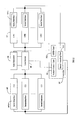
- FIG. 1 is an abbreviated block diagram of architecture of a modem testing system in accordance with an exemplary embodiment of the present invention
- FIG. 2 is an abbreviated block diagram of architecture of a modem testing system in accordance with another exemplary embodiment of the present invention
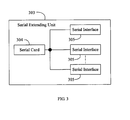
- FIG. 3 is a block diagram of a serial extending unit of a controller of the modem testing system of FIG. 2;
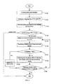
- FIG. 4 is a flowchart of a modem testing method implemented using either of the modem testing systems of FIG. 1 and FIG. 2;
- FIG. 5 is a flowchart of details of one step of FIG. 4, namely capturing and calculating BERs of link data, and displaying the link data and testing results.
- CPE represents various types of modems such as analog modems and xDSL (Digital Subscriber Line) modems.
- CO represents a DSLAM unit or a DLC (Digital Line Carrier) based central office terminal unit.
- the modem testing system is used for testing interoperability of plural or multiple COs and CPEs.
- the modem testing system includes a hub 20, a controller 30, a switch 40, and a line simulator 50.
- the controller 30 may be an appropriate computer as is known in the art.
- the controller 30 has a hard drive, which stores several testing specifications according to various modem types. For example, if the modem testing system is used for testing ADSL (Asymmetric Digital Subscriber Line) modems, the controller 30 stores at least a TR-048 or a TR-067 specification, both of which are specified by the DSL Forum.
- the controller 30 includes an Ethernet card 300, a switch control card 301, and a GPIB (General Purpose Interface Bus) card 302.
- the controller 30 is connected to the hub 20 via the Ethernet card 300, for connecting to the CPEs 10 and the COs 60.
- the controller 30 controls the switch 40 via the switch control card 301 for automatically switching connections between the COs 60 and the CPEs 10, and controls the line simulator 50 via the GPIB card 302 for simulating lines such as two twisted-pair telephone lines.
- the switch 40 is connected to the COs 60, the CPEs 10, and the line simulator 50.
- the switch 40 includes a plurality of relays (not shown) controlled by the controller 30, for switching the connections between the COs 60 and the CPEs 10.
- the line simulator 50 is connected to the switch 40 via two twisted-pair telephone lines for communicating with the CPEs 10 and the COs 60, and simulates various types of lines and noise statuses under the control of the controller 30.
- the line simulator 50 simulates cable characteristics specified in the International Telecommunications Union - Telecommunication (ITU-T) Recommendation (Rec.) G.996.1 for 70 degrees Fahrenheit.
- the line simulator 50 is calibrated relative to the nominal attenuation as defined in ITU-T Rec. G.996.1. Noise can be injected through a high impedance network as specified in G.996.1, with simultaneous noise injection at both ends of the line.
- noise injection is calibrated as defined in ITU-T Rec. G.996.1. Note that in G.996.1, crosstalk models are intended for injection at a single end of the line; whereas noise in the TR-048 specification is injected at both ends simultaneously in order to reduce testing time. It is understood that noise levels on short lines can be up to 3 dB.
- each of the CPEs 10 and the COs 60 respectively includes an Ethernet interface 101a and an Ethernet interface 601a for connecting to the hub 20.
- the COs 60 are typically manufactured by various manufacturers, the modem testing system can be used for testing the interoperability between various types of CPEs 10 and COs 60.
- the controller 30 assigns a unique ID, such as a static and unique IP address, for each of the CPEs 10 and the COs 60.
- a unique ID such as a static and unique IP address
- Each of the IDs corresponds to a respective one of the CPEs 10 or COs 60.
- FIG. 2 architecture of a modem testing system in accordance with another exemplary embodiment is shown.
- a controller 30' is connected to CPEs 10' and COs 60' via a serial extending unit 303 such as an RS-232 extending unit.
- a serial extending unit 303 such as an RS-232 extending unit.
- each of the CPEs 10' and COs 60' respectively has a serial interface 101b or 601b, such as an RS-232 interface.
- Other elements and configurations of this exemplary embodiment are the same as those of the embodiment of FIG. 1.
- FIG. 3 is a block diagram of the serial extending unit 303.
- the serial extending unit 303 includes a serial card 304 and a plurality of or multiple serial interfaces 305.
- the serial card 304 plugs into the PCI bus of the controller 30'.
- the serial interfaces 305 communicate with the serial card 304 via serial buses.
- Each of the serial interfaces 305 is connected to a respective one of the serial interfaces 101b of the CPEs 10' or a respective one of the serial interfaces 601b of the COs 60'.
- a fixed and unique ID is manually assigned for each of the serial interfaces 305.
- Each of the IDs corresponds to a respective one of the CPEs 10 or COs 60, according to a mapping list set up by the controller 30'.
- step S701 the controller 30 or 30' loads testing specifications.
- the testing specifications are typically based on international standards, according to the types of CPEs 10 under test. For example, if multiple ADSL modems are to be tested, at least a TR-048 or TR-067 testing specification needs to be uploaded to the controller 30 or 30'.
- step S702 the controller 30 or 30' sets up a mapping list of the CPEs 10 or 10' and COs 60 or 60'.
- the mapping list includes amounts of the CPEs 10 or 10' and COs 60 or 60', testing sequences of the CPEs 10 or 10' and COs 60 or 60', and the IDs of the CPEs 10 or 10' and COs 60 or 60'.
- step S703 the controller 30 or 30' selects testing specifications in accordance with the types of CPEs 10 or 10', and defines process values for controlling the testing process.
- the testing specifications are included in the testing specifications loaded by the controller 30 or 30' in step S701.
- the process values include a maximum time, represented by K, of the connections set up by the CPEs 10 and COs 60, an interval between a current testing loop and a next testing loop, whole testing loops represented by N, and a minimum time, represented by X, of lasting connections between the CPEs 10 or 10' and COs 60 or 60'.
- step S704 the controller 30 or 30' verifies step 5701, step S702 and step S703. That is, the controller 30 or 30' checks whether the mapping list is correctly set up, whether the correct testing specifications are selected, and whether the correct process values are defined. If there is any error or fault in performing step S701, step S702 or step S703, the controller 30 or 30' terminates the process. If there is no error or fault in performing step S701, step S702 and step S703, the process then proceeds to step S705.
- step S705 the controller 30 or 30' sets up connections between the CPEs 10 or 10' and the COs 60 or 60'. Firstly, the controller 30 or 30' sets up a connection between one of the CPEs 10 or 10' and the line simulator 50 via the switch 40, while a password of that CPE 10 or 10' is required to input into the controller 30 or 30'. Secondly, the controller 30 or 30' sets up a connection between one of the COs 60 or 60' and the line simulator 50 via the switch 40, while a password of that CO 60 or 60' is required to input into the controller 30 or 30'. A connection is thus successfully set up between one of the CPEs 10 or 10' and one of the COs 60 or 60' via the switch 40 and the line simulator 50. Similarly, other connections between other CPEs 10 or 10' and COs 60 or 60' are set up in other testing loops.
- step S706 the controller 30 or 30' controls the line simulator 50 to simulate various types of lines and noise statuses.
- the line simulator 50 is first required to simulate an American Wire Gauge line and a white noise.
- the line simulator 50 then changes the white noise to a 5T1 type noise.
- the 5T1 type noise is stronger than the white noise, and thus the connections between the CPEs 10 or 10' and COs 60 or 60' may be interrupted. If the connections are interrupted, the CPEs 10 or 10' under test will try to set up connections with the COs 60 or 60'.
- step S707 the controller 30 or 30' determines a successful connection time, represented by t, and compares t with K in accordance with the testing specifications selected in step S703. For example, in the process of testing ADSL modems, the maximum value of K is 60 seconds as defined in the TR-048 testing specification. If t . ⁇ K, this indicates that the CPEs 10 or 10' under test are successfully connected to the COs 60 or 60. The process then proceeds to step S708. If t>K, this indicates that the CPEs 10 or 10' under test have failed to connect to the COs 60 or 60'. The process then proceeds to step S708', where the controller 30 or 30' logs an ID or IDs of the failed CPE(s) 10 or 10'.
- step S708 the controller 30 or 30' calculates BERs (Bit Error Rates) of second link data (see below).
- the controller 30 or 30' also displays the link data, testing results of amounts of CPEs 10 or 10' that failed the above testing process, and the ID or IDs of the failed CPE(s) 10 or 10'. The process then proceeds to step S709.
- BERs Bit Error Rates
- step S709 the controller 30 or 30' checks one or more of the process values in order to validate whether the whole testing process is completed.
- step S708 this is a flowchart of details of step S708, namely capturing and calculating BERs of link data, and displaying the link data and testing results.
- step S7081 the controller 30 or 30' captures first link data from the CPEs 10 or 10' and the COs 60 or 60'.
- the first link data includes downstream/upstream rates, SNRs (Signal to Noise Ratios), line attenuation values (in dB), and so on.
- step S7082 the controller 30 or 30' detects a continuous connection time (represented by T) between the CPEs 10 or 10' and COs 60 or 60'.
- the continuous connection time is calculated as being from a successful connection time to a link breaking time.
- step S7083 the controller 30 or 30' captures second link data from the CPEs 10 or 10' and COs 60 or 60'.
- the second link data includes CRC (Cyclic Redundancy Check) data, FEC (Forward Error Correction) data, HEC (Header Error Check) data, and so on.
- step S7084 the controller 30 or 30' compares T with a standard minimum time X. If T ⁇ X, this indicates that the connection quality between the CPEs 10 or 10' and COs 60 or 60' is poor. The process then proceeds to step S7085. If T ⁇ X, this indicates that the connection quality between the CPEs 10 or 10' and COs 60 or 60' meets the requirement(s) of the testing specifications, such as TR-048 and TR-067. The process then proceeds directly to step S7086.
- step S7086 the controller 30 or 30' displays the link data including first link data and second link data, testing results of amounts of CPEs 10 or 10' that failed the above-described testing process, and an ID or IDs of the failed CPE(s) 10 or 10'. The process then proceeds to step S709 described above.
Landscapes
- Engineering & Computer Science (AREA)
- Signal Processing (AREA)
- Computer Networks & Wireless Communication (AREA)
- Maintenance And Management Of Digital Transmission (AREA)
- Telephonic Communication Services (AREA)
Abstract
A modem testing system is provided for testing interoperability of plural items of customer premises equipment (CPEs) (10) and plural central offices (COs) (60). The modem testing system includes a line simulator (50), a switch (40), and a controller (30). The line simulator is connected to the CPEs and COs for simulating various types of lines and noise statuses. The switch is connected to the line simulator, the CPEs, and the COs for switching connections between the CPEs and the COs. The controller is connected to the line simulator, the switch, the CPEs, and the COs for controlling the switch to set up communications between the CPEs and the COs according to a mapping list, and controlling the line simulator to simulate various types of lines and noises statuses. An exemplary modem testing method is also provided.
Description
- The present invention pertains to network device testing systems and methods, and particularly to modem testing systems and methods.
- In the area of network communications, a central office (CO) and customer premises equipment (CPE) are dynamically interoperable if they have common and compatible features, functions and options. The CPE and the CO can provide satisfactory mutual communication in a real network architecture environment if a proper performance test can be applied beforehand. The test conditions need to be appropriately selected and varied during testing. Therefore, it is very important for a modem manufacturer to set up a proper test platform to test interoperability between the CO and the CPE.
- A typical modem testing system includes a processor, and a line simulator interposed between the CPE and the CO. The processor is for controlling the line simulator to simulate a line length, controlling the CPE to train with the CO, and saving data related to the modem training.
- The aforementioned modem testing system can only be used for testing a single CPE with a single CO at one time. It cannot be used for testing multiple CPEs with multiple COs. Thus, the efficiency of testing is low.
- Therefore, a heretofore unaddressed need exists in the industry to overcome the aforementioned deficiencies and inadequacies.
- An exemplary modem testing system is provided, for testing interoperability of plural items of customer premises equipment (CPEs) and plural central offices (COs). The modem testing system includes a line simulator, a switch, and a controller. The line simulator is connected to the CPEs and COs for simulating various types of lines and noise statuses. The switch is connected to the line simulator, the CPEs, and the COs for switching connections between the CPEs and the COs. The controller is connected to the line simulator, the switch, the CPEs, and the COs, for controlling the switch to set up communications between the CPEs and the COs according to a mapping list, and controlling the line simulator to simulate various types of lines and noises statuses.
- An exemplary modem testing method is also provided. The modem testing method is performed with a modem testing system including a switch, a line simulator, and a controller. The controller is for controlling a plurality of items of customer premises equipment (CPES) and a plurality of central offices (COs). The modem testing method includes: loading testing specifications; setting up a mapping list of the CPEs and the COs; selecting testing specifications, and defining process values; setting up connections between the CPEs and the COs; simulating various types of lines and noise statuses; capturing and calculating bit error rates (BERs) of link data; displaying the link data, and testing results of amounts, if any, of one or more CPEs that fail the testing process and one or more IDs of the failed CPEs; and checking one or more of the process values in order to validate whether the whole testing process is completed.
- Other advantages and novel features will be drawn from the following detailed description of exemplary embodiments with the attached drawings, in which:
- FIG. 1 is an abbreviated block diagram of architecture of a modem testing system in accordance with an exemplary embodiment of the present invention;
- FIG. 2 is an abbreviated block diagram of architecture of a modem testing system in accordance with another exemplary embodiment of the present invention;
- FIG. 3 is a block diagram of a serial extending unit of a controller of the modem testing system of FIG. 2;
- FIG. 4 is a flowchart of a modem testing method implemented using either of the modem testing systems of FIG. 1 and FIG. 2; and
- FIG. 5 is a flowchart of details of one step of FIG. 4, namely capturing and calculating BERs of link data, and displaying the link data and testing results.
- In the following description, for the purposes of conveniently explaining various embodiments, the following meanings of terms are assumed. The term "CPE" represents various types of modems such as analog modems and xDSL (Digital Subscriber Line) modems. The term "CO" represents a DSLAM unit or a DLC (Digital Line Carrier) based central office terminal unit.
- Referring to FIG. 1, architecture of a modem testing system in accordance with an exemplary embodiment is shown. The modem testing system is used for testing interoperability of plural or multiple COs and CPEs. The modem testing system includes a
hub 20, acontroller 30, aswitch 40, and aline simulator 50. To further - In the exemplary embodiment, the
controller 30 may be an appropriate computer as is known in the art. Thecontroller 30 has a hard drive, which stores several testing specifications according to various modem types. For example, if the modem testing system is used for testing ADSL (Asymmetric Digital Subscriber Line) modems, thecontroller 30 stores at least a TR-048 or a TR-067 specification, both of which are specified by the DSL Forum. Thecontroller 30 includes an Ethernetcard 300, aswitch control card 301, and a GPIB (General Purpose Interface Bus)card 302. Thecontroller 30 is connected to thehub 20 via the Ethernetcard 300, for connecting to theCPEs 10 and theCOs 60. Thecontroller 30 controls theswitch 40 via theswitch control card 301 for automatically switching connections between theCOs 60 and theCPEs 10, and controls theline simulator 50 via the GPIBcard 302 for simulating lines such as two twisted-pair telephone lines. - In the exemplary embodiment, the
switch 40 is connected to theCOs 60, theCPEs 10, and theline simulator 50. Theswitch 40 includes a plurality of relays (not shown) controlled by thecontroller 30, for switching the connections between theCOs 60 and theCPEs 10. - In the exemplary embodiment, the
line simulator 50 is connected to theswitch 40 via two twisted-pair telephone lines for communicating with theCPEs 10 and theCOs 60, and simulates various types of lines and noise statuses under the control of thecontroller 30. For example, if the modem testing system is used for testing ADSL modems, theline simulator 50 simulates cable characteristics specified in the International Telecommunications Union - Telecommunication (ITU-T) Recommendation (Rec.) G.996.1 for 70 degrees Fahrenheit. Theline simulator 50 is calibrated relative to the nominal attenuation as defined in ITU-T Rec. G.996.1. Noise can be injected through a high impedance network as specified in G.996.1, with simultaneous noise injection at both ends of the line. The noise injection is calibrated as defined in ITU-T Rec. G.996.1. Note that in G.996.1, crosstalk models are intended for injection at a single end of the line; whereas noise in the TR-048 specification is injected at both ends simultaneously in order to reduce testing time. It is understood that noise levels on short lines can be up to 3 dB. - In the exemplary embodiment, each of the
CPEs 10 and theCOs 60 respectively includes anEthernet interface 101a and anEthernet interface 601a for connecting to thehub 20. Although theCOs 60 are typically manufactured by various manufacturers, the modem testing system can be used for testing the interoperability between various types ofCPEs 10 andCOs 60. - In the exemplary embodiment, for identifying the
CPEs 10 and theCOs 60, thecontroller 30 assigns a unique ID, such as a static and unique IP address, for each of theCPEs 10 and theCOs 60. Each of the IDs corresponds to a respective one of theCPEs 10 orCOs 60. - Referring to FIG. 2, architecture of a modem testing system in accordance with another exemplary embodiment is shown. In this exemplary embodiment, instead of having the Ethernet
card 300 of the embodiment of FIG. 1, a controller 30' is connected to CPEs 10' and COs 60' via a serial extendingunit 303 such as an RS-232 extending unit. For connecting to the controller 30', each of the CPEs 10' and COs 60' respectively has aserial interface - FIG. 3 is a block diagram of the serial extending
unit 303. The serial extendingunit 303 includes aserial card 304 and a plurality of or multipleserial interfaces 305. Theserial card 304 plugs into the PCI bus of the controller 30'. Theserial interfaces 305 communicate with theserial card 304 via serial buses. Each of theserial interfaces 305 is connected to a respective one of theserial interfaces 101b of the CPEs 10' or a respective one of theserial interfaces 601b of the COs 60'. In addition, a fixed and unique ID is manually assigned for each of theserial interfaces 305. Each of the IDs corresponds to a respective one of theCPEs 10 orCOs 60, according to a mapping list set up by the controller 30'. - Referring to FIG. 4, this is a flowchart of a modem testing method implemented using either of the above-described embodiments of a modem testing system. First, in step S701, the
controller 30 or 30' loads testing specifications. The testing specifications are typically based on international standards, according to the types ofCPEs 10 under test. For example, if multiple ADSL modems are to be tested, at least a TR-048 or TR-067 testing specification needs to be uploaded to thecontroller 30 or 30'. - In step S702, the
controller 30 or 30' sets up a mapping list of theCPEs 10 or 10' andCOs 60 or 60'. The mapping list includes amounts of theCPEs 10 or 10' andCOs 60 or 60', testing sequences of theCPEs 10 or 10' andCOs 60 or 60', and the IDs of theCPEs 10 or 10' andCOs 60 or 60'. - In step S703, the
controller 30 or 30' selects testing specifications in accordance with the types ofCPEs 10 or 10', and defines process values for controlling the testing process. The testing specifications are included in the testing specifications loaded by thecontroller 30 or 30' in step S701. The process values include a maximum time, represented by K, of the connections set up by theCPEs 10 andCOs 60, an interval between a current testing loop and a next testing loop, whole testing loops represented by N, and a minimum time, represented by X, of lasting connections between theCPEs 10 or 10' andCOs 60 or 60'. In the exemplary embodiment, N is equal to m (the amount ofCPEs 10 or 10') multiplied by n (the amount ofCOs 60 or 60'); that is, N=mxn. In the process of testing, after aCPE 10 or 10' has finished testing, the value of N is automatically reduced by 1. If and when the value of N reaches 0, this indicates that the whole testing process is completed. - In step S704, the
controller 30 or 30' verifies step 5701, step S702 and step S703. That is, thecontroller 30 or 30' checks whether the mapping list is correctly set up, whether the correct testing specifications are selected, and whether the correct process values are defined. If there is any error or fault in performing step S701, step S702 or step S703, thecontroller 30 or 30' terminates the process. If there is no error or fault in performing step S701, step S702 and step S703, the process then proceeds to step S705. - In step S705, the
controller 30 or 30' sets up connections between theCPEs 10 or 10' and theCOs 60 or 60'. Firstly, thecontroller 30 or 30' sets up a connection between one of theCPEs 10 or 10' and theline simulator 50 via theswitch 40, while a password of thatCPE 10 or 10' is required to input into thecontroller 30 or 30'. Secondly, thecontroller 30 or 30' sets up a connection between one of theCOs 60 or 60' and theline simulator 50 via theswitch 40, while a password of thatCO 60 or 60' is required to input into thecontroller 30 or 30'. A connection is thus successfully set up between one of theCPEs 10 or 10' and one of theCOs 60 or 60' via theswitch 40 and theline simulator 50. Similarly, other connections betweenother CPEs 10 or 10' andCOs 60 or 60' are set up in other testing loops. - In step S706, the
controller 30 or 30' controls theline simulator 50 to simulate various types of lines and noise statuses. For example, in the process of testing ADSL modems, theline simulator 50 is first required to simulate an American Wire Gauge line and a white noise. Theline simulator 50 then changes the white noise to a 5T1 type noise. The 5T1 type noise is stronger than the white noise, and thus the connections between theCPEs 10 or 10' andCOs 60 or 60' may be interrupted. If the connections are interrupted, theCPEs 10 or 10' under test will try to set up connections with theCOs 60 or 60'. - In step S707, the
controller 30 or 30' determines a successful connection time, represented by t, and compares t with K in accordance with the testing specifications selected in step S703. For example, in the process of testing ADSL modems, the maximum value of K is 60 seconds as defined in the TR-048 testing specification. If t .<K, this indicates that theCPEs 10 or 10' under test are successfully connected to theCOs CPEs 10 or 10' under test have failed to connect to theCOs 60 or 60'. The process then proceeds to step S708', where thecontroller 30 or 30' logs an ID or IDs of the failed CPE(s) 10 or 10'. In step S708, thecontroller 30 or 30' calculates BERs (Bit Error Rates) of second link data (see below). Thecontroller 30 or 30' also displays the link data, testing results of amounts ofCPEs 10 or 10' that failed the above testing process, and the ID or IDs of the failed CPE(s) 10 or 10'. The process then proceeds to step S709. - In step S709, the
controller 30 or 30' checks one or more of the process values in order to validate whether the whole testing process is completed. In the exemplary embodiment, thecontroller 30 or 30' checks the value of N. If N=0, this indicates that the whole testing process is completed. If N>0, this indicates that the whole testing process is not completed. In the latter case, the process then goes back to step S705 to test theCPEs 10 or 10' that have not yet been tested. - Referring to FIG. 5, this is a flowchart of details of step S708, namely capturing and calculating BERs of link data, and displaying the link data and testing results.
- In step S7081, the
controller 30 or 30' captures first link data from theCPEs 10 or 10' and theCOs 60 or 60'. The first link data includes downstream/upstream rates, SNRs (Signal to Noise Ratios), line attenuation values (in dB), and so on. - In step S7082, the
controller 30 or 30' detects a continuous connection time (represented by T) between theCPEs 10 or 10' andCOs 60 or 60'. The continuous connection time is calculated as being from a successful connection time to a link breaking time. - In step S7083, the
controller 30 or 30' captures second link data from theCPEs 10 or 10' andCOs 60 or 60'. The second link data includes CRC (Cyclic Redundancy Check) data, FEC (Forward Error Correction) data, HEC (Header Error Check) data, and so on. - In step S7084, the
controller 30 or 30' compares T with a standard minimum time X. If T ≧ X, this indicates that the connection quality between theCPEs 10 or 10' andCOs 60 or 60' is poor. The process then proceeds to step S7085. If T < X, this indicates that the connection quality between theCPEs 10 or 10' andCOs 60 or 60' meets the requirement(s) of the testing specifications, such as TR-048 and TR-067. The process then proceeds directly to step S7086. - In step S7085, the
controller 30 or 30' calculates BERs of the second link data, such as the CRC data. If HEC is included in the CRC, thecontroller 30 or 30' calculates the BERs of the CRC data according to the formula BER=CRC/(R*T). If HEC is not included in the CRC, the formula applied is BER=(CRC+HEC)/(R*T). The purpose of calculating the BERs of the CRC data is to verify the connection quality between theCPEs 10 or 10' and theCOs 60 or 60'. The process then proceeds to step S7086. - In step S7086, the
controller 30 or 30' displays the link data including first link data and second link data, testing results of amounts ofCPEs 10 or 10' that failed the above-described testing process, and an ID or IDs of the failed CPE(s) 10 or 10'. The process then proceeds to step S709 described above. - The above-described embodiments and method can be applied for testing any kind of analog or digital modems, including various types of Digital Subscriber Line (DSL) equipment.
- It should be understood that various alternatives and modifications could be devised by those skilled in the art. The present invention is intended to embrace all such alternatives, modifications and variations that fall within the scope of the appended claims and their equivalents.
Claims (17)
- A modem testing system for testing interoperability of plural items of customer premises equipment (CPEs) and plural central offices (COs) comprising:a line simulator connected to the CPEs and COs, for simulating various types of lines and noise statuses;a switch connected to the line simulator, the CPEs, and the COs, for switching connections between the CPEs and the COs; anda controller connected to the line simulator, the switch, the CPEs, and the COs, for controlling the switch to set up communications between the CPEs and the COs according to a mapping list, and controlling the line simulator to simulate various types of lines and noises statuses.
- A modem testing system as claimed in claim 1, wherein the controller captures link data from the CPEs and the COs.
- A modem testing system as claimed in claim 1 or 2, wherein the controller displays link data, and testing results of amounts of one or more CPEs that fail the testing process and one or more IDs of the failed CPEs.
- A modem testing system as claimed in claim 1, wherein the controller defines process values to control the testing process.
- A modem testing system as claimed in any preceding claim further comprising a hub connected to the controller, the CPEs, and the COs.
- A modem testing system as claimed in claim 5, wherein the controller assigns a unique ID to each of the CPEs and the COs.
- A modem testing system as claimed in any preceding claim, wherein the controller further comprises a serial extending unit connected to the CPEs and COs.
- A modem testing system as claimed in claim 7, wherein the serial extending unit comprises a serial card, and a plurality of serial interfaces connected to the serial card respectively.
- A modem testing system as claimed in claim 8, wherein each of the serial interfaces in the serial extending unit has a unique ID.
- A modem testing method for use in a modem testing system comprising a switch, a line simulator, and a controller, the controller controlling the switch, the line simulator, and a plurality of items of customer premises equipment (CPEs) and a plurality of central offices (COs), the modem testing method comprising:loading testing specifications;setting up a mapping list of the CPEs and the COs;selecting testing specifications, and defining process values;setting up connections between the CPEs and the COs;simulating various types of lines and noise statuses;capturing and calculating bit error rates (BERs) of link data;displaying the link data, and testing results of amounts, if any, of one or more CPEs that fail the testing process and one or more IDs of the failed CPEs; andchecking one or more of the process values in order to validate whether the whole testing process is completed.
- A modem testing method as claimed in claim 10, wherein the mapping list comprises amounts of the CPEs and the COs, testing sequences of the CPEs, and IDs of the CPE and the COs.
- A modem testing method as claimed in claim 10 or 11, wherein the process values comprise a maximum time of connections, an interval between a current testing loop and a next testing loop, an amount of the testing loops, and a minimum time of lasting connections between the CPEs and the COs.
- A modem testing method as claimed in any of claims 10 to 12 further comprising:capturing first link data from the CPEs and the COs;determining continuous connection times between the CPEs and the COs;comparing the continuous connection times with a standard minimum time;capturing second link data from the CPEs and the COs;calculating BERs of the second link data; anddisplaying the link data and the testing results.
- A modem testing method as claimed in claim 13, wherein the first link data comprise one or more downstream rates, upstream rates, Signal to Noise Ratios (SNRs), and/or line attenuation values.
- A modem testing method as claimed in claim 13 or 14, wherein the second link data comprise cyclic redundancy check (CRC) data, forward error correction (FEC) data, and header error check (HEC) data.
- A modem testing method as claimed in claim 15, wherein the BERs are calculated according to the formula BER=CRC/(RxT).
- A modem testing method as claimed in claim 15, wherein the BERs are calculated according to the formula BER=(CRC+HEC)/(RxT).
Applications Claiming Priority (1)
| Application Number | Priority Date | Filing Date | Title |
|---|---|---|---|
| CN200510034294A CN1848873B (en) | 2005-04-15 | 2005-04-15 | Modem testing system and method |
Publications (1)
| Publication Number | Publication Date |
|---|---|
| EP1713244A1 true EP1713244A1 (en) | 2006-10-18 |
Family
ID=36685856
Family Applications (1)
| Application Number | Title | Priority Date | Filing Date |
|---|---|---|---|
| EP06251075A Withdrawn EP1713244A1 (en) | 2005-04-15 | 2006-02-28 | System and method for testing a modem |
Country Status (4)
| Country | Link |
|---|---|
| US (1) | US7657418B2 (en) |
| EP (1) | EP1713244A1 (en) |
| JP (1) | JP2006304296A (en) |
| CN (1) | CN1848873B (en) |
Cited By (1)
| Publication number | Priority date | Publication date | Assignee | Title |
|---|---|---|---|---|
| WO2012067552A1 (en) * | 2010-11-16 | 2012-05-24 | Telefonaktiebolaget Lm Ericsson (Publ) | MODULAR UNIT FOR SIMULATING PERFORMANCE IN MULTI-LINES DIGITAL SUBSCRIBER LINE (xDSL) SYSTEM |
Families Citing this family (17)
| Publication number | Priority date | Publication date | Assignee | Title |
|---|---|---|---|---|
| KR100476456B1 (en) * | 2003-02-05 | 2005-03-17 | 삼성전자주식회사 | xDSL Transceiver Unit-Central office Performance, Characteristics and Compatibility Tester and Method thereof |
| DE102006011829B4 (en) * | 2006-03-13 | 2015-10-22 | Bayerische Motoren Werke Aktiengesellschaft | Method for data communication |
| TWI325702B (en) * | 2006-08-18 | 2010-06-01 | Hon Hai Prec Ind Co Ltd | Xdsl modem testing system and method |
| US8225143B2 (en) * | 2008-01-28 | 2012-07-17 | International Business Machines Corporation | Method and apparatus to inject noise in a network system |
| CN101552645A (en) * | 2008-04-02 | 2009-10-07 | 鸿富锦精密工业(深圳)有限公司 | Multipath testing equipment |
| US20090252207A1 (en) * | 2008-04-03 | 2009-10-08 | Ronald Brost | Methods and apparatus to test a central office digital subscriber line modem |
| CN101626433B (en) * | 2008-07-08 | 2013-08-28 | 鸿富锦精密工业(深圳)有限公司 | Device and method for testing modem interface |
| TW201138428A (en) * | 2010-04-20 | 2011-11-01 | Hon Hai Prec Ind Co Ltd | Apparatus and method for testing multiple image transfer channels |
| CN102469214B (en) * | 2010-10-29 | 2014-10-29 | 英业达股份有限公司 | Modem module testing system and method |
| TW201220298A (en) * | 2010-11-01 | 2012-05-16 | Hon Hai Prec Ind Co Ltd | Apparatus and method for testing multiple voice input channel |
| CN102185733B (en) * | 2011-04-13 | 2014-04-02 | 宝德科技集团股份有限公司 | Network card testing method and system |
| US10976359B2 (en) | 2012-09-01 | 2021-04-13 | Promptlink Communications, Inc. | Functional verification process and universal platform for high-volume reverse logistics of CPE devices |
| US10419957B2 (en) * | 2014-05-15 | 2019-09-17 | Promptlink Communications, Inc. | High-volume wireless device testing |
| CN104065530A (en) * | 2014-06-05 | 2014-09-24 | 武汉精测电子技术股份有限公司 | Automatic testing method and system of powerline adapter |
| CN105652180A (en) * | 2014-12-04 | 2016-06-08 | 上海精密计量测试研究所 | FLEX-based balance modem test circuit |
| CN109889674A (en) * | 2019-03-29 | 2019-06-14 | 上海剑桥科技股份有限公司 | Test macro |
| CN111083298B (en) * | 2019-12-12 | 2020-12-15 | 烽火通信科技股份有限公司 | Method and system for testing power modem |
Citations (1)
| Publication number | Priority date | Publication date | Assignee | Title |
|---|---|---|---|---|
| US6690720B1 (en) * | 1999-03-15 | 2004-02-10 | Telesector Resources Group, Inc. | Automated testing of modem training |
Family Cites Families (6)
| Publication number | Priority date | Publication date | Assignee | Title |
|---|---|---|---|---|
| US6044107A (en) * | 1996-05-09 | 2000-03-28 | Texas Instruments Incorporated | Method for interoperability of a T1E1.4 compliant ADSL modem and a simpler modem |
| JPH10336179A (en) * | 1997-05-30 | 1998-12-18 | Fujitsu Ltd | Line testing method |
| CA2281208A1 (en) * | 1999-08-31 | 2001-02-28 | Nortel Networks Corporation | Single-ended subscriber loop qualification for xdsl service |
| CN1130860C (en) * | 2000-05-22 | 2003-12-10 | 英业达股份有限公司 | Method for automatically testing modems |
| JP3807334B2 (en) * | 2002-03-25 | 2006-08-09 | 株式会社リコー | Modem evaluation system |
| KR100476456B1 (en) * | 2003-02-05 | 2005-03-17 | 삼성전자주식회사 | xDSL Transceiver Unit-Central office Performance, Characteristics and Compatibility Tester and Method thereof |
-
2005
- 2005-04-15 CN CN200510034294A patent/CN1848873B/en not_active Expired - Fee Related
- 2005-12-30 US US11/322,871 patent/US7657418B2/en active Active
-
2006
- 2006-02-28 EP EP06251075A patent/EP1713244A1/en not_active Withdrawn
- 2006-04-11 JP JP2006109203A patent/JP2006304296A/en active Pending
Patent Citations (1)
| Publication number | Priority date | Publication date | Assignee | Title |
|---|---|---|---|---|
| US6690720B1 (en) * | 1999-03-15 | 2004-02-10 | Telesector Resources Group, Inc. | Automated testing of modem training |
Non-Patent Citations (3)
| Title |
|---|
| AKUJUOBI, C.M.; ALAM, S.: "Development of an automation process for ADSL interoperability and reliability tests", PROCEEDINGS OF THE THIRTY-SEVENTH SOUTHEASTERN SYMPOSIUM ON SYSTEM THEORY, 20 March 2005 (2005-03-20), pages 239 - 243, XP009070266 * |
| AWARE: "CPE Interoperability testing using DSL forum TR-048", WHITE PAPER, 2002, XP002392488 * |
| DSL FORUM: "ADSL Interoperability Test Plan", TECHNICAL REPORT TR-048, April 2002 (2002-04-01), XP002392489 * |
Cited By (1)
| Publication number | Priority date | Publication date | Assignee | Title |
|---|---|---|---|---|
| WO2012067552A1 (en) * | 2010-11-16 | 2012-05-24 | Telefonaktiebolaget Lm Ericsson (Publ) | MODULAR UNIT FOR SIMULATING PERFORMANCE IN MULTI-LINES DIGITAL SUBSCRIBER LINE (xDSL) SYSTEM |
Also Published As
| Publication number | Publication date |
|---|---|
| CN1848873B (en) | 2010-05-26 |
| US7657418B2 (en) | 2010-02-02 |
| JP2006304296A (en) | 2006-11-02 |
| US20060233228A1 (en) | 2006-10-19 |
| CN1848873A (en) | 2006-10-18 |
Similar Documents
| Publication | Publication Date | Title |
|---|---|---|
| US7657418B2 (en) | Modern testing system and method | |
| US7324456B2 (en) | Apparatus and method for testing an xDSL transceiver unit-central office | |
| US6002671A (en) | Test instrument for testing asymmetric digital subscriber lines | |
| EP1995885B1 (en) | Method and device for obtaining crosstalk information | |
| US9154595B2 (en) | Handheld subscriber line test equipment | |
| US20050135566A1 (en) | Predicting performance of telephone lines for data services | |
| US8027807B2 (en) | DSL diagnosis expert system and method | |
| CN101908909B (en) | Far end crosstalk channel estimation method and device | |
| JP2003338878A (en) | Communication system, multiplexer included in the system, line transmission characteristic test method, and program | |
| CN104662882B (en) | Method and apparatus for testing subscriber premise equipment | |
| CN101364818A (en) | Apparatus for measuring crosstalk and related methods | |
| US9130655B2 (en) | Methods and systems for detecting metallic faults affecting communications links | |
| CN100582795C (en) | A bus parameter calibration method and system | |
| CN101834679A (en) | Port test method, device and system | |
| US7254217B2 (en) | Fault characterization using information indicative of echo | |
| JP2007507181A (en) | Failure identification method and apparatus in broadband network | |
| US7724810B2 (en) | Communication interface and testing method therefore | |
| EP2007071B1 (en) | An emulation test device and method | |
| US5677941A (en) | Channel test unit | |
| EP2103170B1 (en) | Method for the status analysis of a subscriber loop to support broadband telecommunication services | |
| US7478015B2 (en) | System for measuring the effect of an ADSL splitter | |
| TWI294247B (en) | Modem testing system and method | |
| EP1816790A1 (en) | Communication interface and testing method therefore | |
| WO2008029079A1 (en) | Communications circuit test | |
| WO2014075829A1 (en) | Method and device for determining a length value of a section of a telecommunication line |
Legal Events
| Date | Code | Title | Description |
|---|---|---|---|
| PUAI | Public reference made under article 153(3) epc to a published international application that has entered the european phase |
Free format text: ORIGINAL CODE: 0009012 |
|
| AK | Designated contracting states |
Kind code of ref document: A1 Designated state(s): AT BE BG CH CY CZ DE DK EE ES FI FR GB GR HU IE IS IT LI LT LU LV MC NL PL PT RO SE SI SK TR |
|
| AX | Request for extension of the european patent |
Extension state: AL BA HR MK YU |
|
| AKX | Designation fees paid | ||
| REG | Reference to a national code |
Ref country code: DE Ref legal event code: 8566 |
|
| STAA | Information on the status of an ep patent application or granted ep patent |
Free format text: STATUS: THE APPLICATION IS DEEMED TO BE WITHDRAWN |
|
| 18D | Application deemed to be withdrawn |
Effective date: 20070419 |