EP1713103B1 - Electrolytic capacitors having a polymeric outer layer and process of their production - Google Patents
Electrolytic capacitors having a polymeric outer layer and process of their production Download PDFInfo
- Publication number
- EP1713103B1 EP1713103B1 EP06075763A EP06075763A EP1713103B1 EP 1713103 B1 EP1713103 B1 EP 1713103B1 EP 06075763 A EP06075763 A EP 06075763A EP 06075763 A EP06075763 A EP 06075763A EP 1713103 B1 EP1713103 B1 EP 1713103B1
- Authority
- EP
- European Patent Office
- Prior art keywords
- dispersion
- process according
- optionally substituted
- conductive polymer
- solid electrolyte
- Prior art date
- Legal status (The legal status is an assumption and is not a legal conclusion. Google has not performed a legal analysis and makes no representation as to the accuracy of the status listed.)
- Active
Links
Images

Classifications
-
- H—ELECTRICITY
- H01—ELECTRIC ELEMENTS
- H01G—CAPACITORS; CAPACITORS, RECTIFIERS, DETECTORS, SWITCHING DEVICES OR LIGHT-SENSITIVE DEVICES, OF THE ELECTROLYTIC TYPE
- H01G9/00—Electrolytic capacitors, rectifiers, detectors, switching devices, light-sensitive or temperature-sensitive devices; Processes of their manufacture
- H01G9/004—Details
- H01G9/022—Electrolytes; Absorbents
- H01G9/025—Solid electrolytes
- H01G9/028—Organic semiconducting electrolytes, e.g. TCNQ
-
- H—ELECTRICITY
- H01—ELECTRIC ELEMENTS
- H01G—CAPACITORS; CAPACITORS, RECTIFIERS, DETECTORS, SWITCHING DEVICES OR LIGHT-SENSITIVE DEVICES, OF THE ELECTROLYTIC TYPE
- H01G11/00—Hybrid capacitors, i.e. capacitors having different positive and negative electrodes; Electric double-layer [EDL] capacitors; Processes for the manufacture thereof or of parts thereof
- H01G11/22—Electrodes
- H01G11/30—Electrodes characterised by their material
- H01G11/48—Conductive polymers
-
- H—ELECTRICITY
- H01—ELECTRIC ELEMENTS
- H01G—CAPACITORS; CAPACITORS, RECTIFIERS, DETECTORS, SWITCHING DEVICES OR LIGHT-SENSITIVE DEVICES, OF THE ELECTROLYTIC TYPE
- H01G11/00—Hybrid capacitors, i.e. capacitors having different positive and negative electrodes; Electric double-layer [EDL] capacitors; Processes for the manufacture thereof or of parts thereof
- H01G11/54—Electrolytes
- H01G11/56—Solid electrolytes, e.g. gels; Additives therein
-
- H—ELECTRICITY
- H01—ELECTRIC ELEMENTS
- H01G—CAPACITORS; CAPACITORS, RECTIFIERS, DETECTORS, SWITCHING DEVICES OR LIGHT-SENSITIVE DEVICES, OF THE ELECTROLYTIC TYPE
- H01G9/00—Electrolytic capacitors, rectifiers, detectors, switching devices, light-sensitive or temperature-sensitive devices; Processes of their manufacture
- H01G9/0029—Processes of manufacture
- H01G9/0032—Processes of manufacture formation of the dielectric layer
-
- H—ELECTRICITY
- H01—ELECTRIC ELEMENTS
- H01G—CAPACITORS; CAPACITORS, RECTIFIERS, DETECTORS, SWITCHING DEVICES OR LIGHT-SENSITIVE DEVICES, OF THE ELECTROLYTIC TYPE
- H01G9/00—Electrolytic capacitors, rectifiers, detectors, switching devices, light-sensitive or temperature-sensitive devices; Processes of their manufacture
- H01G9/0029—Processes of manufacture
- H01G9/0036—Formation of the solid electrolyte layer
-
- H—ELECTRICITY
- H01—ELECTRIC ELEMENTS
- H01G—CAPACITORS; CAPACITORS, RECTIFIERS, DETECTORS, SWITCHING DEVICES OR LIGHT-SENSITIVE DEVICES, OF THE ELECTROLYTIC TYPE
- H01G9/00—Electrolytic capacitors, rectifiers, detectors, switching devices, light-sensitive or temperature-sensitive devices; Processes of their manufacture
- H01G9/004—Details
- H01G9/04—Electrodes or formation of dielectric layers thereon
- H01G9/042—Electrodes or formation of dielectric layers thereon characterised by the material
-
- Y—GENERAL TAGGING OF NEW TECHNOLOGICAL DEVELOPMENTS; GENERAL TAGGING OF CROSS-SECTIONAL TECHNOLOGIES SPANNING OVER SEVERAL SECTIONS OF THE IPC; TECHNICAL SUBJECTS COVERED BY FORMER USPC CROSS-REFERENCE ART COLLECTIONS [XRACs] AND DIGESTS
- Y02—TECHNOLOGIES OR APPLICATIONS FOR MITIGATION OR ADAPTATION AGAINST CLIMATE CHANGE
- Y02E—REDUCTION OF GREENHOUSE GAS [GHG] EMISSIONS, RELATED TO ENERGY GENERATION, TRANSMISSION OR DISTRIBUTION
- Y02E60/00—Enabling technologies; Technologies with a potential or indirect contribution to GHG emissions mitigation
- Y02E60/13—Energy storage using capacitors
-
- Y—GENERAL TAGGING OF NEW TECHNOLOGICAL DEVELOPMENTS; GENERAL TAGGING OF CROSS-SECTIONAL TECHNOLOGIES SPANNING OVER SEVERAL SECTIONS OF THE IPC; TECHNICAL SUBJECTS COVERED BY FORMER USPC CROSS-REFERENCE ART COLLECTIONS [XRACs] AND DIGESTS
- Y10—TECHNICAL SUBJECTS COVERED BY FORMER USPC
- Y10T—TECHNICAL SUBJECTS COVERED BY FORMER US CLASSIFICATION
- Y10T29/00—Metal working
- Y10T29/53—Means to assemble or disassemble
- Y10T29/5313—Means to assemble electrical device
- Y10T29/532—Conductor
- Y10T29/53204—Electrode
Definitions
- the invention relates to a method for producing low equivalent series resistance, low leakage current electrolytic capacitors consisting of a solid electrolyte of conductive polymers and an outer layer containing conductive polymers, electrolytic capacitors produced by this method, and the use of such electrolytic capacitors.
- a commercially available solid electrolytic capacitor is usually composed of a porous metal electrode, an oxide layer on the metal surface, an electrically conductive solid introduced into the porous structure, an external electrode (contacting), such as an electrode. a silver layer, as well as other electrical contacts and an encapsulation.
- solid electrolytic capacitors are tantalum, aluminum, niobium and niobium oxide capacitors with charge transfer complexes, brownstone or polymer solid electrolytes.
- porous bodies has the advantage that, due to the large surface area, a very high capacity density, i. high electrical capacity in a small space.
- ⁇ -conjugated polymers due to their high electrical conductivity.
- ⁇ -conjugated polymers are also referred to as conductive polymers or as synthetic metals. They are increasingly gaining economic importance because polymers have advantages over metals in terms of processability, weight, and targeted chemical properties modification.
- Examples of known ⁇ -conjugated polymers are polypyrroles, polythiophenes, polyanilines, polyacetylenes, polyphenylenes and poly (p-phenylenevinylenes), a particularly important and industrially used polythiophene being the poly-3,4- (ethylene-1,2-dioxy ) Thiophene, often referred to as poly (3,4-ethylenedioxythiophene), is because it has a very high conductivity in its oxidized form.
- ESR equivalent series resistances
- EP-A-340 512 describes the preparation of a solid electrolyte from 3,4-ethylene-1,2-dioxythiophene and the use of its produced by oxidative polymerization, cationic polymers as a solid electrolyte in electrolytic capacitors.
- Poly (3,4-ethylenedioxythiophene) as a substitute for manganese dioxide or charge-transfer complexes in solid electrolytic capacitors lowers the equivalent series resistance of the capacitor due to its higher electrical conductivity and improves the frequency response.
- an approximately 5-50 ⁇ m thick outer layer of conductive polymers on the capacitor anode serves as a mechanical buffer between the capacitor anode and the cathode-side contact. This prevents that e.g. the silver layer (contacting) comes into direct contact with the dielectric under mechanical stress or damages it, thereby increasing the residual current of the capacitor.
- the conductive polymeric outer layer itself should have a so-called self-healing behavior: Smaller defects in the dielectric on the outer anode surface that occur despite the buffering effect are electrically isolated by destroying the conductivity of the outer layer at the defect site by the electric current.
- a dense electrically conductive outer layer with good edge coverage can be achieved by electrochemical polymerization.
- the electrochemical polymerization requires that first a conductive film is deposited on the insulating oxide layer of the capacitor anode and then this layer is electrically contacted for each individual capacitor. This contacting is very expensive in mass production and can damage the oxide layer.
- the use of formulations containing the powder of a conductive polymer and binder have too high an electrical resistance due to high contact resistances between the individual powder particles to allow the production of low ESR solid electrolytic capacitors.
- the solid electrolyte is formed by two electrically conductive polymer layers: the first layer is formed by means of chemical oxidative polymerization and the second layer consists of a conductive polymer and a binder.
- PEDT / PSS polyethylene dioxythiophene / polystyrenesulfonic acid
- PEDT / PSS polyethylene dioxythiophene / polystyrenesulfonic acid
- the outer layer is then applied to this layer by means of in situ polymerization or by impregnation of the capacitor anode with Tetracyanoquinodimethan salt solution.
- this method has the disadvantage that the PEDT / PSS complex does not penetrate into porous anode bodies with small pores. As a result, modern, highly porous anode materials can not be used.
- German patent application DE-A-10 2004 022 674 is a polymeric outer layer by applying a dispersion comprising at least one polymeric anion and at least one optionally substituted polyaniline and / or at least one polythiophene having repeating units of the general formula (I), (II) or recurring units of the general formula (I) and (II ) and creates a binder.
- edge banding can be improved with this method, it is not possible to reliably produce dense polymeric outer layers.
- dispersions containing particles of a conductive polyaniline and / or in particular polythiophene having an average particle diameter in the range of 70-500 nm and a binder fulfill these requirements.
- the diameter distribution of the particles b) containing a conductive polymer in dispersions surprisingly has a considerable influence on the formation of outer layers on electrolytic capacitors.
- dispersions containing predominantly particles b) having an average diameter of less than 70 nm in particular the edges and corners of the capacitor body can not be covered with a closed polymer film.
- the targeted adjustment of the particle diameter distribution in the dispersions thus makes it possible to reproducibly achieve good corner and edge coverage.
- the diameter of the particles b) of the conductive polymer refers to a mass distribution of the particles b) in the dispersion a) as a function of the particle diameter. It takes place for example via an ultracentrifuge measurement.
- the particles b) of the conductive polymer in the dispersion a) preferably have an average diameter of 90-400 nm, particularly preferably 100-300 nm, in the processes according to the invention.
- the diameter distribution of the particles b) of the conductive polymer in the dispersion a) has a d 10 value greater than 50 nm and a d 90 value less than 600 nm, particularly preferably a d 10 value greater than 70 nm and a d 90 value less than 500 nm, very particularly preferably a d 10 value greater than 80 nm and a d 90 value less than 400 nm.
- the d 10 value of the diameter distribution means that 10% of the total mass of all particles b) of the conductive polymer in the dispersion a) can be assigned to particles b) having a diameter smaller than or equal to the d 10 value.
- the d 90 value of the diameter distribution states that 90% of the total mass of all particles b) of the conductive polymer in the dispersion a) can be assigned to those particles b) having a diameter smaller than or equal to the d 90 value.
- the electrode material forms in the electrolytic capacitor produced by the method according to the invention a porous body with a high surface area, and is e.g. in the form of a porous sintered body or a roughened film.
- this porous body will also be referred to for short as the electrode body.
- the electrode body covered with a dielectric is also referred to below as the oxidized electrode body.
- the term "oxidized electrode body” also includes those electrode bodies that are covered with a dielectric that was not produced by oxidation of the electrode body.
- the electrode body covered with a dielectric as well as completely or partially with a solid electrolyte is also referred to below for short as the capacitor body.
- the electrically conductive layer which is prepared by the process according to the invention from the dispersion a) and which comprises at least one optionally substituted polyaniline and / or at least one polythiophene having repeating units of the general formula (I) or the formula (II) or recurring units of the general formula (I) Formula (I) and (II) and at least one binder c) is referred to herein as a polymeric outer layer.
- the dispersion contains a) at least one polymeric, organic binder c).
- polymeric, organic binders c) are, for example, polyvinyl alcohols, polyvinylpyrrolidones, polyvinyl chlorides, polyvinyl acetates, polyvinyl butyrates, polyacrylic acid esters, polyacrylic acid amides, polymethacrylic acid esters, polymethacrylic acid amides, polyacrylonitriles, styrene / acrylate esters, Vinyl acetate / Acrylklareester- and ethylene / vinyl acetate copolymers, polybutadienes, polyisoprenes, polystyrenes, polyethers, polyesters, polycarbonates, polyurethanes, polyamides, polyimides, polysulfones, melamine Formaldehyharze, epoxy resins, silicone resins or celluloses in question.
- polymeric organic binders c) are also those which are suitable by adding crosslinkers such as, for example, melamine compounds, blocked isocyanates or functional silanes, for example 3-glycidoxypropyltrialkoxysilane, tetraethoxysilane and tetraethoxysilane hydrolyzate, or crosslinkable polymers, for example polyurethanes, polyacrylates or polyolefins and subsequent networking can be generated.
- crosslinking products suitable as polymeric binders c) can also be formed, for example, by reaction of the added crosslinkers with polymeric anions optionally present in the dispersion a). Preference is given to those binders c) which have sufficient temperature stability to withstand the temperature stresses to which the finished capacitors are later exposed, for example soldering temperatures of 220 to 260 ° C.
- the solids content of the polymeric binder c) in the dispersion a) is 0.1-90% by weight, preferably 0.5-30% by weight and very particularly preferably 0.5-10% by weight.
- the dispersions a) may contain one or more dispersants d).
- dispersants d) which may be mentioned are the following solvents: aliphatic alcohols, such as methanol, ethanol; i-propanol and butanol; aliphatic ketones such as acetone and methyl ethyl ketone; aliphatic carboxylic acid esters such as ethyl acetate and butyl acetate; aromatic hydrocarbons such as toluene and xylene; aliphatic hydrocarbons such as hexane, heptane and cyclohexane; Chlorinated hydrocarbons such as dichloromethane and dichloroethane; aliphatic nitriles such as acetonitrile, aliphatic sulfoxides and sulfones such as dimethylsulfoxide and sulfolane; aliphatic carboxylic acid amides such as methylacetamide, di
- Preferred dispersants d) are water or other protic solvents such as alcohols, e.g. Methanol, ethanol, i-propanol and butanol, and mixtures of water with these alcohols, particularly preferred solvent is water.
- alcohols e.g. Methanol, ethanol, i-propanol and butanol
- water particularly preferred solvent is water.
- the binder c) can act as a dispersant d).
- polymers encompasses all compounds having more than one identical or different repeat unit.
- conductive polymers in particular the class of compounds of the ⁇ -conjugated polymers, which have an electrical conductivity after oxidation or reduction.
- Such ⁇ -conjugated polymers are preferably understood to be conductive polymers which, after oxidation, have an electrical conductivity of the order of magnitude of at least 1 ⁇ S cm -1 .
- the prefix poly- is understood to mean that more than one identical or different recurring unit is contained in the polymer or polythiophene.
- the polythiophenes contain a total of n repeating units of the general formula (I) or formula (II) or the general formulas (I) and (II), wherein n is an integer from 2 to 2000, preferably 2 to 100, is.
- the recurring units of general formula (I) and / or (II) may be the same or different within each polythiophene. Preference is given to polythiophenes having in each case the same recurring units of the general formula (I), (II) or (I) and (II).
- the polythiophenes preferably carry H.
- the solid electrolyte may contain as conductive polymers optionally substituted polythiophenes, optionally substituted polypyrroles or optionally substituted polyanilines.
- Preferred conductive polymers for the solid electrolyte are polythiophenes having recurring units of the general formula (I), (II) or recurring units of the general formula (I) and (II) in which A, R and x are as defined above for the general formulas (I) and (II).
- polythiophenes having repeating units of the general formula (I), (II) or recurring units of the general formula (I) and (II) in which A is an optionally substituted C 2 -C 3 -alkylene radical and x is 0 or 1 stands.
- the conductive polymer of the solid electrolyte is poly (3,4-ethylenedioxythiophene).
- C 1 -C 5 -alkylene radicals A are preferably methylene, ethylene, n-propylene, n-butylene or n-pentylene.
- C 1 -C 18 -alkyl R are preferably linear or branched C 1 -C 18 -alkyl radicals such as methyl, ethyl, n- or iso-propyl, n-, iso-, sec- or tert-butyl, n-pentyl, 1-methylbutyl, 2-methylbutyl, 3-methylbutyl, 1-ethylpropyl, 1,1-dimethylpropyl, 1,2-dimethylpropyl, 2,2-dimethylpropyl, n-hexyl, n-heptyl, n-octyl, 2-ethylhexyl, n-nonyl, n-decyl, n-undecyl, n-dodecyl
- radicals A and / or the radicals R are numerous organic groups, for example alkyl, cycloalkyl, aryl, aralkyl, alkoxy, halogen, ether, thioether, disulfide, sulfoxide, Sulfonic, sulfonate, amino, aldehyde, keto, carboxylic ester, carboxylic acid, carbonate, carboxylate, cyano, alkylsilane and alkoxysilane groups and carboxylamide groups.
- organic groups for example alkyl, cycloalkyl, aryl, aralkyl, alkoxy, halogen, ether, thioether, disulfide, sulfoxide, Sulfonic, sulfonate, amino, aldehyde, keto, carboxylic ester, carboxylic acid, carbonate, carboxylate, cyano, alkylsilane and alkoxysilane groups and carboxylamide groups.
- Suitable substituents for polyaniline are, for example, the abovementioned radicals A and R and / or the further substituents of the radicals A and R in question. Preference is given to unsubstituted polyanilines.
- the polythiophenes used as solid electrolyte in the preferred process may be neutral or cationic. In preferred embodiments, they are cationic, with "cationic" referring only to the charges sitting on the polythiophene backbone.
- the polythiophenes may carry positive and negative charges in the structural unit, with the positive charges on the polythiophene main chain and the negative charges optionally being on the radicals R substituted by sulfonate or carboxylate groups. In this case, the positive charges of the polythiophene main chain can be partially or completely saturated by the optionally present anionic groups on the radicals R. Overall, the polythiophenes in these cases can be cationic, neutral or even anionic.
- the positive charges on the polythiophene main chain are relevant.
- the positive charges are not shown in the formulas because their exact number and position can not be determined properly. However, the number of positive charges is at least 1 and at most n, where n is the total number of all repeating units (equal or different) within the polythiophene.
- the cationic polythiophenes require anions as counterions.
- Counterions may be monomeric or polymeric anions, the latter also referred to below as polyanions.
- Polymeric anions for use in the solid electrolyte can be, for example, anions of polymeric carboxylic acids, such as polyacrylic acids, polymethacrylic acid or polymaleic acids, or polymeric sulfonic acids, such as polystyrenesulfonic acids and polyvinylsulfonic acids. These polycarboxylic and sulfonic acids may also be copolymers of vinyl carboxylic and vinyl sulfonic acids with other polymerizable monomers such as acrylic acid esters and styrene.
- polymeric carboxylic acids such as polyacrylic acids, polymethacrylic acid or polymaleic acids
- polymeric sulfonic acids such as polystyrenesulfonic acids and polyvinylsulfonic acids.
- These polycarboxylic and sulfonic acids may also be copolymers of vinyl carboxylic and vinyl sulfonic acids with other polymerizable monomers such as acrylic acid esters and styrene.
- monomeric anions are preferably used, since these penetrate better into the oxidized electrode body.
- Examples of monomeric anions are those of C 1 -C 20 -alkanesulfonic acids, such as methane, ethane, propane, butane or higher sulfonic acids, such as dodecanesulfonic acid, of aliphatic perfluorosulfonic acids, such as trifluoromethanesulfonic acid, perfluorobutanesulfonic acid or perftuorooctanesutfonic acid, of aliphatic C 1 -C 20 -carboxylic acids such as 2-ethylhexylcarboxylic acid, aliphatic perfluorocarboxylic acids such as trifluoroacetic acid or perfluorooctanoic acid, and aromatic, optionally substituted by C 1 -C 20 alkyl sulfonic acids such as benzenesulfonic acid, o-toluenesulfonic acid, p Toluenesulfonic acid or dode
- Cationic polythiophenes which contain anions as counterions for charge compensation are also often referred to in the art as polythiophene / (poly) anion complexes.
- the solid electrolyte may contain binders, crosslinkers, surface-active substances, such as e.g. ionic or nonionic surfactants or adhesion promoters and / or other additives.
- Adhesion promoters are, for example, organofunctional silanes or their hydrolysates, e.g. 3-glycidoxypropyltrialkoxysilane, 3-aminopropyltriethoxysilane, 3-mercaptopropyltrimethoxysilane, 3-metacryloxypropyltrimethoxysilane, vinyltrimethoxysilane or octyltriethoxysilane.
- organofunctional silanes or their hydrolysates e.g. 3-glycidoxypropyltrialkoxysilane, 3-aminopropyltriethoxysilane, 3-mercaptopropyltrimethoxysilane, 3-metacryloxypropyltrimethoxysilane, vinyltrimethoxysilane or octyltriethoxysilane.
- the solid electrolyte preferably consists of the conductive polymer and monomeric anions as counter ions.
- the solid electrolyte preferably forms on the dielectric surface a layer with a thickness of less than 200 nm, more preferably less than 100 nm, most preferably less than 50 nm.
- the coverage of the dielectric with the solid electrolyte can be determined as follows: The capacitance of the capacitor is measured in the dry and wet state at 120 Hz. The degree of coverage is the ratio of the capacity in the dry state to the capacity in the wet state expressed as a percentage. Dry state means that the condenser was dried for several hours at elevated temperature (80-120 ° C) before being measured. Wet condition means that the condenser is exposed to saturated air humidity at elevated pressure over several hours, for example in a steam pressure vessel. The moisture penetrates into pores that are not covered by the solid electrolyte, where it acts as a liquid electrolyte.
- the coverage of the dielectric by the solid electrolyte is preferably greater than 50%, more preferably greater than 70%, most preferably greater than 80%.
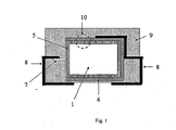
- the polymeric outer layer is preferably as shown schematically and by way of example in FIG Fig. 1 and Fig. 2 represented on the whole or a part of the outer surface of the capacitor body.
- the outer surface is understood to mean the outer surfaces of the capacitor body.
- geometric surface refers to the outer surface of the capacitor body 1, which results from the geometric dimensions.
- L is the length
- B is the width
- H is the height of the body and * is a multiplication sign.
- L is the length
- B is the width
- H is the height of the body
- * is a multiplication sign. In this case, only the part of the capacitor body 1 is considered, on which the polymeric outer layer is located.
- dimensions of the developed film are used as dimensions.
- the solid electrolytic capacitors may also include solid electrolytes containing a non-polymeric conductive material, such as charge transfer complexes, e.g. TCNQ (7,7,8,8-tetracyano-1,4-quinodimethane), manganese dioxide or salts, e.g. those which can form ionic liquids contain. Even with such solid electrolytic capacitors, the polymeric outer layer leads to lower residual currents.
- a non-polymeric conductive material such as charge transfer complexes, e.g. TCNQ (7,7,8,8-tetracyano-1,4-quinodimethane), manganese dioxide or salts, e.g. those which can form ionic liquids contain.
- a counterion for the polyanilines and / or the phenylthiophenes of said particles b) with repeating units of the general formula (I), (II) or recurring units of the general Formula (I) and (II) in dispersion a) may be polymeric or monomeric anions.
- polymeric anions in dispersion a) preferably serve as counterions.
- Polymeric anions can here be, for example, anions of polymeric carboxylic acids, such as polyacrylic acids, polymethacrylic acid or polymaleic acids, or polymeric sulfonic acids, such as polystyrenesulfonic acids and polyvinylsulfonic acids. These polycarboxylic and sulfonic acids may also be copolymers of vinyl carboxylic and vinyl sulfonic acids with other polymerizable monomers such as acrylic acid esters and styrene.
- polymeric carboxylic acids such as polyacrylic acids, polymethacrylic acid or polymaleic acids
- polymeric sulfonic acids such as polystyrenesulfonic acids and polyvinylsulfonic acids.
- These polycarboxylic and sulfonic acids may also be copolymers of vinyl carboxylic and vinyl sulfonic acids with other polymerizable monomers such as acrylic acid esters and styrene.
- polystyrene sulfonic acid PSS
- the molecular weight of the polyanions yielding polyacids is preferably from 1 000 to 2 000 000, more preferably from 2 000 to 500 000.
- the polyacids or their alkali metal salts are commercially available, for example polystyrenesulfonic acids and polyacrylic acids, or can be prepared by known methods (see, for example Houben Weyl, Methods of Organic Chemistry, Vol. E 20 Macromolecular Substances, Part 2, (1987), p. 1141 uf).
- Polymer (s) anion (s) and electrically conductive polymers may in the dispersion a) in particular in a weight ratio of 0.5: 1 to 50: 1, preferably from 1: 1 to 30: 1, more preferably 2: 1 to 20 : 1 be included.
- the weight of the electrically conductive polymers corresponds to the initial weight of the monomers used, assuming that complete conversion takes place during the polymerization.
- the dispersion a) may also contain monomeric anions.
- the same preferred anions apply to the monomeric anions as listed above for the solid electrolyte.
- the dispersion a) may also contain other components such as surfactants, e.g. ionic and nonionic surfactants or coupling agents, e.g. organofunctional silanes or their hydrolysates, e.g. 3-Glycidoxypropyltrialkoxysilane, 3-aminopropyltriethoxysilane, 3-mercaptopropyltrimethoxysilane, 3-metacryloxypropyltrimethoxysilane, vinyltrimethoxysilane or octyltriethoxysilane.
- surfactants e.g. ionic and nonionic surfactants or coupling agents
- organofunctional silanes or their hydrolysates e.g. 3-Glycidoxypropyltrialkoxysilane, 3-aminopropyltriethoxysilane, 3-mercaptopropyltrimethoxysilane, 3-metacryloxypropyltrimethoxysilane, vinyltrimethoxy
- the thickness of the polymeric outer layer is preferably 1-1000 ⁇ m, particularly preferably 1-100 ⁇ m, very particularly preferably 2-50 ⁇ m, in particular particularly preferably 4-20 ⁇ m.
- the layer thickness can vary on the outer surface. In particular, the layer thickness at the edges of the capacitor body may be thicker or thinner than on the side surfaces of the capacitor body. However, a nearly homogeneous layer thickness is preferred.
- the polymeric outer layer may have a homogeneous or inhomogeneous distribution with respect to its composition with respect to the binders c) and conductive polymers. Preference is given to homogeneous distributions.
- the polymeric outer layer may be part of a multilayer system that forms the outer layer of the capacitor body.
- one or more further functional layers eg adhesion promoter layers
- the electrical function of the polymeric outer layer should not be affected thereby.
- several polymeric outer layers may be located on the capacitor body.
- the polymeric outer layer is directly on the solid electrolyte.
- the polymeric outer layer preferably penetrates into the edge region of the capacitor body in order to achieve a good electrical contact with the solid electrolyte and to increase the adhesion to the capacitor body, but not in the entire depth of all pores (cf. Fig.2 ).
- the electrolytic capacitor produced by the new method contains a solid electrolyte containing poly (3,4-ethylenedioxythiophene) (PEDT) and a polymeric outer layer containing polystyrenesulfonic acid (PSS) and poly (3,4-ethylenedioxythiophene), the latter being disclosed in U.S. Pat Literature commonly referred to as PEDT / PSS or PEDOT / PSS.
- PEDT poly (3,4-ethylenedioxythiophene)
- PSS polystyrenesulfonic acid
- PSS poly (3,4-ethylenedioxythiophene
- the electrolytic capacitor produced by the new method contains a solid electrolyte of poly (3,4-ethylenedioxythiophene) and monomeric counterions and a polymeric outer layer of PEDT / PSS and a binder c).
- the electrode material is a valve metal or a compound with a valve metal comparable electrical properties.
- metal metals are understood to be metals whose oxide layers do not allow current flow in both directions equally: With anodically applied voltage, the oxide layers of the valve metals block the flow of current, while with cathodically applied voltage large currents occur which destroy the oxide layer can.
- the valve metals include Be, Mg, Al, Ge, Si, Sn, Sb, Bi, Ti, Zr, Hf, V, Nb, Ta and W, and an alloy or joining at least one of these metals with other elements.
- the best known representatives of the valve metals are Al, Ta, and Nb.
- Compounds of valve metal comparable electrical properties are those with metallic conductivity, which are oxidizable and whose oxide layers have the properties described above.
- NbO has metallic conductivity but is generally not considered a valve metal.
- layers of oxidized NbO have the typical properties of valve metal oxide layers such that NbO or an alloy or compound of NbO with other elements are typical examples of such compounds having valve metal comparable electrical properties.
- oxidizable metal means not only metals, but also an alloy or compound of a metal with other elements as long as they have metallic conductivity and are oxidizable.
- the subject of the present invention is accordingly a process for the production of electrolytic capacitors, characterized in that the valve metal or the compound has an electrical properties comparable to valve metal, such as tantalum, niobium, aluminum, titanium, zirconium, hafnium, vanadium, an alloy or Compound of at least one of these metals with other elements, NbO or an alloy or compound of NbO with other elements.
- valve metal or the compound has an electrical properties comparable to valve metal, such as tantalum, niobium, aluminum, titanium, zirconium, hafnium, vanadium, an alloy or Compound of at least one of these metals with other elements, NbO or an alloy or compound of NbO with other elements.
- the dielectric preferably consists of an oxide of the electrode material. It optionally contains further elements and / or compounds.
- the capacity of the oxidized electrode body depends not only on the type of dielectric but also on the surface and the thickness of the dielectric.
- the capacitance results from the capacitance of the finished capacitor measured at 120 Hz and the voltage is the working voltage of the capacitor (rated voltage).
- the weight of the oxidized electrode body refers to the net weight of the dielectric-coated porous electrode material without polymer, contacts, and encapsulations.
- the electrolytic capacitors produced by the novel process preferably have a specific charge greater than 10,000 ⁇ C / g, more preferably greater than 20,000 ⁇ C / g, very preferably greater than 30,000 ⁇ C / g, most preferably greater than 40,000 ⁇ C / g.
- the solid electrolytic capacitor produced by the method according to the invention is characterized by a low residual current and low equivalent series resistance. Since the polymeric outer layer forms a dense layer around the capacitor body and occupies its edges very well, the capacitor body is robust against mechanical stresses. In addition, the polymeric outer layer shows good adhesion to the capacitor body and high electrical conductivity, so that low equivalent series resistances can be achieved.
- Preferred subject matter of the invention are electrolytic capacitors produced by the novel process, which have an ESR measured at 100 kHz of less than 50 m ⁇ . More preferably, the ESR of the electrolytic capacitors produced by the new method, measured at a frequency of 100 kHz, is less than 31 milliohms, most preferably less than 21 milliohms, most preferably less than 16 milliohms. In particularly preferred embodiments of the electrolytic capacitors, the ESR is smaller 11 m ⁇ .
- the equivalent series resistance of a solid electrolytic capacitor correlates inversely with the geometric surface of the capacitor.
- the product of the equivalent series resistance and the geometric surface thus indicates a size independent of the size.
- the product of the equivalent series resistance measured at 100 kHz and the geometric surface of the capacitor body is less than 4000 m ⁇ mm 2 .
- the product of the equivalent series resistance and the geometric surface is less than 3000 m ⁇ mm 2 , most preferably less than 2000 m ⁇ mm 2 , most preferably less than 1000 m ⁇ mm 2 .
- the product of the equivalent series resistance and the geometric surface area is less than 600 m ⁇ mm 2 .
- such an electrolytic capacitor according to the invention can be manufactured as follows. pressed a valve metal powder having a high surface area and sintered into a porous electrode body. In this case, usually an electrical contact wire made of the same metal of the powder, for. B. tantalum pressed into the electrode body. Alternatively, metal foils may be etched to obtain a porous foil.
- the electrode body is then coated, for example by electrochemical oxidation, with a dielectric, ie an oxide layer.
- a dielectric ie an oxide layer.
- On the dielectric is then z. B. by means of oxidative polymerization chemically or electrochemically a conductive polymer deposited, which forms the solid electrolyte.
- oxidative polymerization chemically or electrochemically a conductive polymer deposited, which forms the solid electrolyte.
- precursors for the preparation of conductive polymers, one or more oxidants and optionally counterions, together or sequentially applied to the dielectric of the porous electrode body and polymerized by chemical oxidative, or precursors for the production of conductive polymers and counterions are polymerized by electrochemical polymerization of the dielectric of the porous electrode body.
- a layer comprising at least one optionally substituted polyaniline and / or a polythiophene having recurring units of the general formula (I), (II) or recurring units of the general formula (I) and (II) and at least one binder is then applied to the capacitor body c) applied from a dispersion a).
- further layers are applied to the polymeric outer layer.
- a coating of highly conductive layers, such as graphite and silver, or a metallic cathode body serves as an electrode to dissipate the current.
- the capacitor is contacted and encapsulated.
- precursors for the preparation of conductive polymers of the solid electrolyte hereinafter also referred to as precursors
- corresponding monomers or their derivatives are understood. It is also possible to use mixtures of different precursors.
- Suitable monomeric precursors are, for example, optionally substituted thiophenes, pyrroles or anilines, preferably optionally substituted thiophenes, particularly preferably optionally substituted 3,4-alkylenedioxythiophenes.
- Very particularly preferred monomeric precursors are optionally substituted 3,4-ethylenedioxythiophenes.
- derivatives of these monomeric precursors are, for example, dimers or trimers of these monomeric precursors. They are also higher molecular weight derivatives, i. Tetramers, pentamers, etc. of the monomeric precursors as derivatives possible.
- the derivatives can be constructed from the same or different monomer units and can be used in pure form and mixed with one another and / or with the monomer precursors.
- oxidized or reduced forms of these precursors are also encompassed by the term "precursors", provided that the same conductive polymers are formed during their polymerization as in the precursors listed above.
- C 1 -C 5 -alkylene radicals A are in the context of the invention methylene, ethylene, n-propylene, n-butylene or n-pentylene.
- C 1 -C 18 -alkyl radicals R in the context of the invention are linear or branched C 1 -C 18 -alkyl radicals, such as, for example, methyl, ethyl, n- or isopropyl, n-, iso-, sec- or tert-butyl, n-pentyl, 1-methylbutyl, 2-methylbutyl, 3-methylbutyl, 1-ethylpropyl, 1,1-dimethylpropyl, 1,2-dimethylpropyl, 2,2-dimethylpropyl, n-hexyl, n-heptyl, n-octyl, 2-ethylhexyl, n-nonyl, n-decyl, n-und
- radicals A and / or the radicals R are numerous organic groups, for example alkyl, cycloalkyl, aryl, aralkyl, alkoxy, halogen, ether, thioether, disulfide, sulfoxide , Sulfonic, sulfonate, amino, aldehyde, keto, carboxylic acid ester, carboxylic acid, carbonate, carboxylate, cyano, alkylsilane and alkoxysilane groups and carboxylamide groups.
- organic groups for example alkyl, cycloalkyl, aryl, aralkyl, alkoxy, halogen, ether, thioether, disulfide, sulfoxide , Sulfonic, sulfonate, amino, aldehyde, keto, carboxylic acid ester, carboxylic acid, carbonate, carboxylate, cyano, alkylsilane and alkoxysilane groups and carboxylamide groups.
- Suitable substituents for the abovementioned precursors are the radicals mentioned for the general formulas (III) and (IV) for R.
- Suitable substituents for pyrroles and anilines are, for example, the abovementioned radicals A and R and / or the further substituents of the radicals A and R in question.
- the conductive polymers are preferably formed on the electrode body covered by a dielectric by oxidative polymerization of precursors for the production of conductive polymer by precursors, oxidants and optionally counterions, preferably in the form of solutions, either separately or together on the dielectric of the electrode body and the oxidative polymerization, depending on the activity of the oxidizing agent used, if appropriate by heating the coating to an end.
- the application may be directly or using a coupling agent, for example a silane, e.g. organofunctional silanes or their hydrolysates, e.g. 3-Glycidoxypropyltrialkoxysilane, 3-aminopropyltriethoxysilane, 3-mercaptopropyltrimethoxysilane, 3-metacryloxypropyltrimethoxysilane, vinyltrimethoxysilane or octyltriethoxysilane., And / or one or more other functional layers to the dielectric of the electrode body.
- a silane e.g. organofunctional silanes or their hydrolysates, e.g. 3-Glycidoxypropyltrialkoxysilane, 3-aminopropyltriethoxysilane, 3-mercaptopropyltrimethoxysilane, 3-metacryloxypropyltrimethoxysilane, vinyltrimethoxysilane or octyltrie
- Suitable solvents for the precursors for the preparation of conductive polymers and / or oxidants and / or counterions are, in particular, the following organic solvents which are inert under the reaction conditions: aliphatic alcohols such as methanol, ethanol, 1-propanol and butanol; aliphatic ketones such as acetone and methyl ethyl ketone; aliphatic carboxylic acid esters such as ethyl acetate and butyl acetate; aromatic hydrocarbons such as toluene and xylene; aliphatic hydrocarbons such as hexane, heptane and cyclohexane; Chlorinated hydrocarbons such as dichloromethane and dichloroethane; aliphatic nitriles such as acetonitrile, aliphatic sulfoxides and sulfones such as dimethylsulfoxide and sulfolane; aliphatic carboxylic acid amide
- oxidizing agent it is possible to use all metal salts known to those skilled in the art for the oxidative polymerization of thiophenes, anilines or pyrroles.
- Suitable metal salts are metal salts of main or subgroup metals, the latter also referred to below as transition metal salts, of the Periodic Table of the Elements.
- Suitable transition metal salts are, in particular, salts of an inorganic or organic acid or inorganic acid containing organic radicals of transition metals, such as e.g. of iron (III), copper (II), chromium (VI), cerium (IV), manganese (IV), manganese (VII) and ruthenium (III).
- Preferred transition metal salts are those of iron (III).
- Conventional ferric salts are advantageously inexpensive, readily available and can be easily handled, such as the ferric salts of inorganic acids such as ferric halides (eg FeCl 3 ) or ferric salts other inorganic acids, such as Fe (ClO 4 ) 3 or Fe 2 (SO 4 ) 3 , and the iron (III) salts of organic acids and organic acids having organic radicals.
- iron (III) salts of organic acids containing inorganic acids are the iron (III) salts of the sulfuric acid monoesters of C 1 -C 20 -alkanols, for example the iron (III) salt of lauryl sulfate.
- transition metal salts are those of an organic acid, especially iron (III) salts of organic acids.
- iron (III) salts of organic acids which may be mentioned are: the iron (III) salts of C 1 -C 20 -alkanesulfonic acids, such as methane, ethane, propane, butane or higher sulfonic acids, such as dodecanesulfonic acid, of aliphatic perfluorosulphonic acids, such as trifluoromethanesulfonic acid, perfluorobutanesulfonic acid or perfluorooctane sulphonic acid, of aliphatic C 1 -C 20 carboxylic acids such as 2-ethylhexylcarboxylic acid, of aliphatic perfluorocarboxylic acids, such as trifluoroacetic acid or perfluorooctanoic acid, and of aromatic is optionally substituted by C 1- C 20 Alkyl groups substituted sulfonic acids such as benzenesulfonic acid, o-toluenesulfonic acid, p
- Iron (III) p-toluenesulfonate, iron (III) o-toiol sulfonate or a mixture of iron (III) p-toluenesulfonate and iron (III) o-toluenesulfonate are very particularly preferred as metal salts.
- peroxo compounds such as peroxodisulfates (persulfates), in particular ammonium and alkali peroxodisulfates, such as sodium and potassium peroxodisulfate, or alkali metal perborates, optionally in the presence of catalytic amounts of metal ions, such as iron, cobalt, nickel, molybdenum or vanadium ions Transition metal oxides, such as Manganese (manganese (IV) oxide) or cerium (IV) oxide.
- persulfates in particular ammonium and alkali peroxodisulfates, such as sodium and potassium peroxodisulfate, or alkali metal perborates
- metal ions such as iron, cobalt, nickel, molybdenum or vanadium ions
- Transition metal oxides such as Manganese (manganese (IV) oxide) or cerium (IV) oxide.
- the dielectric of the electrode body is preferably first coated with the solution of the oxidizing agent and optionally the counterions and subsequently with the solution of the precursors.
- the dielectric of the electrode body is coated with only one, namely a precursor, oxidizing agent and optionally containing counterions solution.
- the solutions may also contain other components such as one or more organic solvents soluble in organic solvents such as polyvinyl acetate, polycarbonate, polyvinyl butyral, polyacrylic acid esters, polymethacrylic acid esters, polystyrene, polyacrylonitrile, polyvinyl chloride, polybutadiene, polyisoprene, polyether, polyester, silicones, styrene / Acrylklareester-, vinyl acetate / Acrylklareester- and ethylene / vinyl acetate copolymers or water-soluble binders such as polyvinyl alcohols, crosslinkers such as melamine compounds, blocked isocyanates, functional silanes - eg tetraethoxysilane, Alkoxysilanhydrolysate, for example based on tetraethoxysilane, epoxysilanes such as 3-glycidoxypropyltrialkoxysilane - polyurethanes, polyacryl
- solutions to be applied to the dielectric of the electrode body preferably contain 1 to 30% by weight of the thiophene of the general formula (III) or the mixture of thiophenes of the general formulas (III) and (IV) and 0 to 50% by weight of binder, Crosslinkers and / or additives, both percentages by weight based on the total weight of the mixture.
- the solutions are prepared by known methods, e.g. by impregnation, pouring, dripping, spraying, spraying, knife coating, brushing, spin coating or printing, for example ink-jet, screen, contact or pad printing, applied to the dielectric of the electrode body.
- the removal of the solvents after the application of the solutions can be carried out by simple evaporation at room temperature. However, to achieve higher processing speeds, it is more advantageous to use the solvents at elevated temperatures, e.g. at temperatures of 20 to 300 ° C, preferably 40 to 250 ° C to remove.
- a thermal aftertreatment can be connected directly with the removal of the solvent or else at a time interval from the completion of the coating.
- the duration of the heat treatment is 5 seconds to several hours depending on the kind of the polymer used for the coating. Temperature profiles with different temperatures and residence times can also be used for the thermal treatment.
- the heat treatment may e.g. be carried out in such a way that one moves the coated oxidized electrode body at such a speed through a heat chamber at the desired temperature, that the desired residence time is reached at the selected temperature, or with a desired temperature at the desired heating plate for the desired residence time brings in contact.
- the heat treatment can be carried out, for example, in one or more heating furnaces, each with different temperatures.
- Residual salts are here to be understood as meaning the salts of the reduced form of the oxidizing agent and optionally further salts present.
- metal oxide dielectrics such as the oxides of the valve metals
- reformation dives Insert the capacitor body into an electrolyte and apply a positive voltage to the electrode body. The flowing current re-forms the oxide at defective points in the oxide film or destroys conductive polymer at defects over which a high current flows.
- oxidized electrode body it may be advantageous to impregnate the oxidized electrode body, preferably after a wash, a further time with the mixtures in order to achieve thicker polymer layers.
- the polythiophenes of the solid electrolyte can also be prepared from the precursors by electrochemical oxidative polymerization.
- the dielectric body coated electrode body may be first coated with a thin layer of conductive polymer. After applying a voltage to this layer, the layer containing the conductive polymer grows thereon.
- Other conductive layers may also be used as the deposition layer. So describe Y. Kudoh et al. in Journal of Power Sources 60 (1996) 157-163 the use of a deposition layer of manganese oxide.
- the electrochemical oxidative polymerization of the precursors can be carried out at temperatures from -78 ° C to the boiling point of the solvent used. Preferably, at temperatures of -78 ° C to 250 ° C, more preferably from -20 ° C to 60 ° C electrochemically polymerized.
- the reaction time is 1 minute to 24 hours, depending on the precursor used, the electrolyte used, the selected temperature and the applied current density.
- the electropolymerization can be carried out in the presence or absence of solvents which are inert under the conditions of electropolymerization; the electropolymerization of solid precursors is carried out in the presence of solvents which are inert under the conditions of electrochemical polymerization.
- solvent mixtures and / or to add solubilizers (detergents) may be advantageous to use solvent mixtures and / or to add solubilizers (detergents) to the solvents.
- inert solvents which can be used under the conditions of electropolymerization are: water; Alcohols such as methanol and ethanol; Ketones such as acetophenone; halogenated hydrocarbons such as methylene chloride, chloroform, carbon tetrachloride and fluorocarbons; Esters such as ethyl acetate and butyl acetate; Carbonic acid esters such as propylene carbonate; aromatic hydrocarbons such as benzene, toluene, xylene; aliphatic hydrocarbons such as pentane, hexane, heptane and cyclohexane; Nitriles such as acetonitrile and benzonitrile; Sulfoxides such as dimethylsulfoxide; Sulfones such as dimethylsulfone, phenylmethylsulfone and sulfolane; liquid aliphatic amides such as methylacetamide, dimethylacetamide, dimethyl
- the precursors or their solutions are mixed with additions of electrolyte.
- the electrolyte additives used are preferably free acids or customary conductive salts which have a certain solubility in the solvents used.
- electrolyte additives e.g.
- free acids such as p-toluenesulfonic acid, methanesulfonic acid, furthermore salts with alkanesulfonate, aromatic sulfonate, tetrafluoroborate, hexafluorophosphate, perchlorate, hexafluoroantimonate, hexafluoroarsenate and hexachloroantimonate anions and alkali metal, alkaline earth metal or optionally alkylated ammonium , Phosphonium, sulfonium and oxonium cations.
- free acids such as p-toluenesulfonic acid, methanesulfonic acid, furthermore salts with alkanesulfonate, aromatic sulfonate, tetrafluoroborate, hexafluorophosphate, perchlorate, hexafluoroantimonate, hexafluoroarsenate and hexachloroanti
- the concentrations of the precursors can be between 0.01 and 100 wt .-% (100 wt .-% only for liquid precursor); Preferably, the concentrations are 0.1 to 20 wt .-%.
- the electropolymerization may be carried out batchwise or continuously.
- the current densities for the electropolymerization can vary within wide limits; Usually, current densities of 0.0001 to 100 mA / cm 2 , preferably 0.01 to 40 mA / cm 2 are used . At these current densities, voltages of about 0.1 to 50 V are established.
- the electrochemical polymerization may be advantageous after the electrochemical polymerization to replicate the oxide film electrochemically to mend any defects in the oxide film and thereby reduce the residual current of the finished capacitor (reforming).
- Suitable counterions are the monomeric or polymeric anions already mentioned above, preferably those of the monomeric or polymeric alkane- or cycloalkanesulfonic acids or aromatic sulfonic acids. Particularly preferred for use in the electrolytic capacitors according to the invention are the anions of the monomeric alkane- or cycloalkanesulfonic acids or aromatic sulfonic acids, since these solutions are better suited to penetrate the porous dielectric material coated with an electrode material, and thus formed a larger contact area between this and the solid electrolyte can be.
- the counterions are added to the solutions, for example in the form of their alkali metal salts or as free acids. In electrochemical polymerization, these counterions are optionally added to the solution or the thiophenes as electrolyte additives or conductive salts.
- the optionally present anions of the oxidizing agent used may serve as counterions, so that in the case of chemical oxidative polymerization, it is not absolutely necessary to add additional counterions.
- the polymeric outer layer is applied as described above.
- binders c) to the dispersion a) has the great advantage that the adhesion of the outer polymer layer to the capacitor body is increased.
- the binder c) increases the solids content in the dispersion, so that even with an impregnation a sufficient outer layer thickness can be achieved and the edge coverage is significantly improved.
- the dispersions a) may also contain crosslinkers, surfactants, e.g. ionic or nonionic surfactants or adhesion promoters, and / or additives.
- crosslinkers e.g. ionic or nonionic surfactants or adhesion promoters
- surfactants and / or additives those listed above for the solid electrolyte may be used.
- the dispersions contain a) other additives which increase the conductivity, e.g. ether group-containing compounds, e.g. Tetrahydrofuran, compounds containing lactone groups, such as ⁇ -butyrolactone, ⁇ -valerolactone, compounds containing amide or lactam groups, such as caprolactam, N-methylcaprolactam, N, N-dimethylacetamide, N-methylacetamide, N, N-dimethylformamide (DMF), N-methylformamide, N- Methylformanilide, N-methylpyrrolidone (NMP), N-octylpyrrolidone, pyrrolidone, sulfones and sulfoxides, such as Sulfolane (tetramethylene sulfone), dimethyl sulfoxide (DMSO), sugars or sugar derivatives, such as e.g.
- ether group-containing compounds e.g. Tetrahydrofuran
- Sucrose glucose, fructose, lactose, sugar alcohols, e.g. Sorbitol, mannitol, furan derivatives, e.g. 2-furancarboxylic acid, 3-furancarboxylic acid, and / or di- or polyalcohols, e.g. Ethylene glycol, glycerol, di- or triethylene glycol ,.
- Particular preference is given to using, as conductivity-increasing additives, tetrahydrofuran, N-methylformamide, N-methylpyrrolidone, ethylene glycol, dimethyl sulfoxide or sorbitol.
- the dispersions a) can have a pH of 1-14, preferably a pH of 1-8.
- a pH of 1-8 For corrosion sensitive dielectrics, such as aluminas, dispersions are preferred with a pH of 4-8, so as not to damage the dielectric.
- the dispersions are prepared from optionally substituted anilines, thiophenes of the general formula (III), (IV) or mixtures of thiophenes of the general formulas (III) and (IV), for example analogously to those in EP-A 440 957 mentioned conditions. Suitable oxidizing agents and solvents are those already mentioned above.
- the diameter distribution The particle b) can be adjusted for example via a high-pressure homogenization.
- a preparation of the polyaniline / polyanion or polythiophene / polyanion complex and subsequent dispersion or redispersion in one or more solvents is also possible.
- the dispersions a) are prepared by known methods, e.g. by spin coating, impregnation, pouring, dripping, spraying, spraying, knife coating, brushing or printing, for example, ink-jet, screen or pad printing applied to the capacitor body.
- the viscosity of the dispersion a) can be between 0.1 and 100,000 mPa ⁇ s (measured at a shear rate of 100 s -1 ).
- the viscosity is preferably from 1 to 10 000 mPa ⁇ s, more preferably from 10 to 1000 mPa ⁇ s, most preferably from 30 to 500 mPa ⁇ s.
- the dispersion a) When applying the dispersion a) to the capacitor body by means of impregnation, it may be advantageous to form a thin film of higher viscosity on the surface of the dispersion a) before impregnation. If the capacitor body is then successively immersed deeper into such a dispersion a) in one or more impregnation and drying cycles, the coverage of the edges and corners of the capacitor body is markedly improved and bubble formation in the dry polymer film is prevented. Thus, for example, in the first step only half of the capacitor body can be soaked in the dispersion a) and then dried. In a second impregnation step, the capacitor body can then be completely immersed in the dispersion a) and then dried.
- the formation of the thin film of higher viscosity on the surface of the dispersion a) can be achieved, for example, by simply standing in an open atmosphere.
- the film formation can be accelerated e.g. by heating the dispersion a) or by heating the dispersion surface with warm air or heat radiation.
- Dispersions a) are preferably used which, when dried, have a specific conductivity of greater than 10 S / cm, more preferably greater than 20 S / cm, very preferably greater than 50 S / cm and most preferably greater than 100 S / cm.
- Drying, cleaning of the layer by washing, reforming and repeated application may also follow the application of the polymeric outer layer, as described above for the preparation of the solid electrolyte.
- the dispersant d) is preferably removed. However, at least a part of the dispersant d) may also remain in the polymeric outer layer.
- crosslinkers can also be applied to other treatment steps such as curing or crosslinking by temperature or light.
- further layers can be applied to the polymeric outer layer.
- the polymeric outer layer After the polymeric outer layer has been produced, it is preferred if desired to apply further highly conductive layers, such as graphite and / or silver layers, to the capacitor, to contact and encapsulate the capacitor.
- further highly conductive layers such as graphite and / or silver layers
- valve metals or compounds with comparable electrical properties listed above for the electrolytic capacitor are preferably used. Preferred areas apply accordingly.
- the oxidizable metals are sintered into a porous electrode body in powder form, or a porous structure is impressed on a metallic body.
- the latter can e.g. by etching a foil.
- the porous electrode bodies are used, for example, in a suitable electrolyte, e.g. Phosphoric acid, oxidized by applying a voltage.
- a suitable electrolyte e.g. Phosphoric acid
- the height of this forming voltage depends on the oxide layer thickness to be achieved or the subsequent application voltage of the capacitor.
- Preferred voltages are 1 to 300 V, more preferably 1 to 80V.
- metal powders having a specific charge greater than 140,000 ⁇ C / g are used.
- the capacity results from the capacity of the oxidized electrode body measured at 120 Hz in an aqueous electrolyte.
- the electrical conductivity of the electrolyte is sufficiently large, so that it does not come at 120 Hz to a capacity drop due to the electrical resistance of the electrolyte.
- 18% aqueous sulfuric acid electrolytes are used for the measurement.
- the voltage in the above formula corresponds to the maximum forming voltage (oxidation voltage).
- the electrolytic capacitors produced according to the invention are outstandingly suitable for use as components in electronic circuits. Preference is given to digital electronic circuits, as used, for example, in computers (desktop, laptop, server), in portable electronic devices, such as mobile phones and digital cameras, in consumer electronic devices, such as in CD / DVD players and computer game consoles, in navigation systems, and in Telecommunications facilities are located.
- Tantalum powder having a specific capacity of 50,000 ⁇ FV / g was pressed into pellets 2 including a tantalum wire 7 and sintered to form a porous electrode body 2 having dimensions of 4.2 mm * 3 mm * 1.6 mm.
- the sintered pellets 2 (anode pellets) were anodized to 30 V in a phosphoric acid electrolyte.
- a solution consisting of one part by weight of 3,4-ethylenedioxythiophene (BAYTRON® M, HC Starck GmbH) and 20 parts by weight of a 40% strength by weight ethanolic solution of iron (III) p-toluenesulfonate (BAYTRON® CE, HC Starck GmbH).
- the solution was used to impregnate 18 anode pellets 2.
- the anode pellets 2 were soaked in this solution and then dried for 30 min at room temperature (20 ° C). Thereafter, they were heat treated at 50 ° C for 30 minutes in a drying oven. Subsequently, the pellets 2 were washed in a 2 wt% aqueous solution of p-toluenesulfonic acid for 30 minutes.
- the anode pellets 2 were reformed for 30 minutes in a 0.25% by weight aqueous solution of p-toluenesulfonic acid, then rinsed in distilled water and dried.
- the described impregnation, drying, temperature treatment and reforming was carried out with the same pellets 2 two more times.
- the poly (3,4-ethylenedioxythiophene) / polystyrene sulfonate dispersion obtained had a solids content of 1.2% by weight and the following particle diameter distribution: d10 100 nm d50 141 nm d90 210 nm
- the diameter of the particles b) of the conductive polymer refers to a mass distribution of the particles b) in the dispersion as a function of the particle diameter. The determination was made by an ultracentrifuge measurement.
- the desalted 3,4-polyethylenedioxythiophene / polystyrenesulfonate dispersion was homogenized 4 times at 250 bar with a high-pressure homogenizer.
- the 3,4-polyethylenedioxythiophene / polystyrenesulfonate dispersion thus obtained had a solids content of 1.2% by weight and the following particle diameter distribution: d10 10 nm d50 31 nm d90 66 nm
- each 9 anode pellets 2 were then soaked in the dispersion A according to the invention and a further 9 pellets 2 in the dispersion B and then dried at 120 ° C. for 10 min. Soaking and drying was repeated for all pellets 2 again.
- the anode pellets were observed after application of the polymeric outer layer 5 under a light microscope:
- the anode pellets 2 according to the invention with the polymeric outer layer 5 based on dispersion A were coated on the entire outer surface with a dense polymer film.
- the edges and corners also showed a continuous polymer film coverage.
- the anode pellets 2 with the polymeric outer layer 5 based on dispersion B showed no polymer film assignment, in particular at the upper corners and edges of the anode.
- pellets 2 were coated with a graphite and silver layer.
- Capacitor from dispersion A Capacitor from dispersion B Residual current in ⁇ A 0.2 7.7
- the residual current was determined three minutes after applying a 10V voltage with a Keithley 199 multimeter.
- the capacitors produced by the process according to the invention using dispersions containing particles b) of a conductive polymer having an average diameter of 141 nm show significantly lower residual currents due to better coverage with a polymeric outer layer 5.
Abstract
Description
Die Erfindung betrifft ein Verfahren zur Herstellung von Elektrolytkondensatoren mit niedrigem äquivalenten Serienwiderstand und niedrigem Reststrom, die aus einem Feststoffelektrolyten aus leitfähigen Polymeren und einer äußeren Schicht enthaltend leitfähige Polymere bestehen, nach diesem Verfahren hergestellte Elektrolytkondensatoren sowie die Verwendung solcher Elektrolytkondensatoren.The invention relates to a method for producing low equivalent series resistance, low leakage current electrolytic capacitors consisting of a solid electrolyte of conductive polymers and an outer layer containing conductive polymers, electrolytic capacitors produced by this method, and the use of such electrolytic capacitors.
Ein handelsüblicher Feststoffelektrolytkondensator besteht in der Regel aus einer porösen Metallelektrode, einer auf der Metalloberfläche befindlichen Oxidschicht, einem elektrisch leitfähigen Feststoff, der in die poröse Struktur eingebracht wird, einer äußeren Elektrode (Kontaktierung), wie z.B. einer Silberschicht, sowie weiteren elektrischen Kontakten und einer Verkapselung.A commercially available solid electrolytic capacitor is usually composed of a porous metal electrode, an oxide layer on the metal surface, an electrically conductive solid introduced into the porous structure, an external electrode (contacting), such as an electrode. a silver layer, as well as other electrical contacts and an encapsulation.
Beispiele für Feststoffelektrolytkondensatoren sind Tantal-, Aluminium, Niob- und Nioboxidkondensatoren mit Ladungstransferkomplexen, Braunstein- oder Polymer-Feststoffelektrolyten. Die Verwendung poröser Körper hat den Vorteil, dass sich aufgrund der großen Oberfläche eine sehr hohe Kapazitätsdichte, d.h. eine hohe elektrische Kapazität auf kleinem Raum, erzielen lässt.Examples of solid electrolytic capacitors are tantalum, aluminum, niobium and niobium oxide capacitors with charge transfer complexes, brownstone or polymer solid electrolytes. The use of porous bodies has the advantage that, due to the large surface area, a very high capacity density, i. high electrical capacity in a small space.
Besonders geeignet als Feststoffelektrolyte sind aufgrund ihrer hohen elektrischen Leitfähigkeit π-konjugierte Polymere. π-konjugierte Polymere werden auch als leitfähige Polymere oder als synthetische Metalle bezeichnet. Sie gewinnen zunehmend an wirtschaftlicher Bedeutung, da Polymere gegenüber Metallen Vorteile bezüglich der Verarbeitbarkeit, des Gewichts und der gezielten Einstellung von Eigenschaften durch chemische Modifikation haben. Beispiele für bekannte π-konjugierte Polymere sind Polypyrrole, Polythiophene, Polyaniline, Polyacetylene, Polyphenylene und Poly(p-phenylen-vinylene), wobei ein besonders wichtiges und technisch genutztes Polythiophen das Poly-3,4-(ethylen-1,2-dioxy)thiophen, oft auch als Poly(3,4-ethylendioxythiophen) bezeichnet, ist, da es in seiner oxidierten Form eine sehr hohe Leitfähigkeit aufweist.Particularly suitable as solid electrolytes are π-conjugated polymers due to their high electrical conductivity. π-conjugated polymers are also referred to as conductive polymers or as synthetic metals. They are increasingly gaining economic importance because polymers have advantages over metals in terms of processability, weight, and targeted chemical properties modification. Examples of known π-conjugated polymers are polypyrroles, polythiophenes, polyanilines, polyacetylenes, polyphenylenes and poly (p-phenylenevinylenes), a particularly important and industrially used polythiophene being the poly-3,4- (ethylene-1,2-dioxy ) Thiophene, often referred to as poly (3,4-ethylenedioxythiophene), is because it has a very high conductivity in its oxidized form.
Die technische Entwicklung in der Elektronik erfordert zunehmend Feststoffelektrolytkondensatoren mit sehr niedrigen Äquivalenten Serienwiderständen (ESR). Grund dafür sind beispielsweise fallende Logikspannungen, eine höhere Integrationsdichte und steigende Taktfrequenzen in integrierten Schaltkreisen. Ferner senkt ein niedriger ESR auch den Energieverbrauch, was besonders für mobile, batteriebetriebene Anwendungen vorteilhaft ist. Es besteht daher der Wunsch, den ESR von Feststoffelektrolytkondensatoren möglichst weit zu reduzieren.The technical development in electronics increasingly requires solid electrolytic capacitors with very low equivalent series resistances (ESR). This is due, for example, to falling logic voltages, a higher integration density and increasing clock frequencies in integrated circuits. Furthermore, a low ESR also lowers power consumption, which is particularly beneficial for mobile, battery-powered applications. There is therefore a desire to reduce the ESR of solid electrolytic capacitors as far as possible.
In der europäischen Patentschrift
Neben einem niedrigen ESR erfordern moderne Feststoffelektrolytkondensatoren einen niedrigen Reststrom und eine gute Stabilität gegenüber externen Belastungen. Insbesondere während des Herstellungsprozesses treten bei der Verkapselung der Kondensatoranoden hohe mechanische Belastungen auf, die den Reststrom der Kondensatoranode stark erhöhen können.In addition to a low ESR, modern solid electrolytic capacitors require a low residual current and good stability against external loads. In particular, during the manufacturing process occur in the encapsulation of the capacitor anodes high mechanical loads that can greatly increase the residual current of the capacitor anode.
Stabilität gegenüber solchen Belastungen und damit ein geringer Reststrom lassen sich vor allem durch eine ca. 5-50 µm dicke Außenschicht aus leitfähigen Polymeren auf der Kondensatoranode erzielen. Eine solche Schicht dient als mechanischer Puffer zwischen der Kondensatoranode und der kathodenseitigen Kontaktierung. Dadurch wird verhindert, dass z.B. die Silberschicht (Kontaktierung) bei mechanischer Belastung mit dem Dielektrikum in direkten Kontakt kommt oder dieses beschädigt und sich dadurch der Reststrom des Kondensators erhöht. Die leitfähige polymere Au-ßenschicht selbst sollte ein so genanntes Selbstheilungsverhalten aufweisen: Kleinere Defekte im Dielektrikum an der äußeren Anodenoberfläche, die trotz der Pufferwirkung auftreten, werden dadurch elektrisch isoliert, dass die Leitfähigkeit der Außenschicht an der Defektstelle durch den elektrischen Strom zerstört wird.Stability against such loads and thus a low residual current can be achieved above all by an approximately 5-50 μm thick outer layer of conductive polymers on the capacitor anode. Such a layer serves as a mechanical buffer between the capacitor anode and the cathode-side contact. This prevents that e.g. the silver layer (contacting) comes into direct contact with the dielectric under mechanical stress or damages it, thereby increasing the residual current of the capacitor. The conductive polymeric outer layer itself should have a so-called self-healing behavior: Smaller defects in the dielectric on the outer anode surface that occur despite the buffering effect are electrically isolated by destroying the conductivity of the outer layer at the defect site by the electric current.
Die Bildung einer dicken polymeren Außenschicht mittels einer in-situ Polymerisation ist sehr schwierig. Die Schichtbildung bedarf dabei sehr vieler Beschichtungszyklen. Durch die große Anzahl an Beschichtungszyklen wird die Außenschicht sehr inhomogen, insbesondere die Kanten der Kondensatoranode werden oftmals unzureichend belegt. Die
Eine dichte elektrisch leitfähige Außenschicht mit guter Kantenbelegung kann durch elektrochemische Polymerisation erreicht werden. Die elektrochemische Polymerisation erfordert jedoch, dass zunächst ein leitfähiger Film auf der isolierenden Oxidschicht der Kondensatoranode abgeschieden wird und diese Schicht dann für jeden einzelnen Kondensator elektrisch kontaktiert wird. Diese Kontaktierung ist in der Massenfertigung sehr aufwendig und kann die Oxidschicht beschädigen.A dense electrically conductive outer layer with good edge coverage can be achieved by electrochemical polymerization. The electrochemical polymerization, however, requires that first a conductive film is deposited on the insulating oxide layer of the capacitor anode and then this layer is electrically contacted for each individual capacitor. This contacting is very expensive in mass production and can damage the oxide layer.
Die Verwendung von Formulierungen, die das Pulver eines leitfähigen Polymers und Binder enthalten, haben aufgrund hoher Kontaktwiderstände zwischen den einzelnen Pulverteilchen einen zu hohen elektrischen Widerstand, als dass sie die Herstellung von Feststoffelektrolytkondensatoren mit niedrigem ESR ermöglichen. In der
In den
In der nicht vorveröffentlichten deutschen Patentanmeldung 
Es besteht somit weiterhin Bedarf an einem verbesserten Verfahren zur Herstellung von Feststoffelektrolytkondensatoren mit niedrigem Äquivalenten Serienwiderstand (ESR), mit dem sich eine dichte polymere Außenschicht mit guter Kantenbelegung einfach und verlässlich reproduzierbar realisieren lässt. Die Aufgabe bestand daher darin, ein solches Verfahren und die damit verbesserten Kondensatoren bereitzustellen.There is thus still a need for an improved process for the production of solid electrolytic capacitors with low equivalent series resistance (ESR), with which a dense polymeric outer layer with good edge coverage can be realized easily and reliably reproducibly. The object was therefore to provide such a method and the capacitors thus improved.
Überraschend wurde nun gefunden, dass Dispersionen enthaltend Teilchen eines leitfähigen Polyanilins und/oder insbesondere Polythiophens mit einem mittleren Teilchendurchmesser im Bereich von 70-500 nm und einem Binder, diese Anforderungen erfüllen.Surprisingly, it has now been found that dispersions containing particles of a conductive polyaniline and / or in particular polythiophene having an average particle diameter in the range of 70-500 nm and a binder fulfill these requirements.
Die Durchmesserverteilung der Teilchen b) enthaltend ein leitfähiges Polymer in Dispersionen hat überraschenderweise einen erheblichen Einfluss auf die Bildung von Außenschichten auf Elektrolytkondensatoren. Mit Dispersionen enthaltend überwiegend Teilchen b) eines mittleren Durchmessers kleiner als 70 nm lassen sich insbesondere die Kanten und Ecken des Kondensatorkörpers nicht mit einem geschlossenen Polymerfilm belegen. Die gezielte Einstellung der Teilchendurchmesserverteilung in den Dispersionen ermöglicht es somit, reproduzierbar eine gute Ecken- und Kantenbelegung zu erzielen.The diameter distribution of the particles b) containing a conductive polymer in dispersions surprisingly has a considerable influence on the formation of outer layers on electrolytic capacitors. With dispersions containing predominantly particles b) having an average diameter of less than 70 nm, in particular the edges and corners of the capacitor body can not be covered with a closed polymer film. The targeted adjustment of the particle diameter distribution in the dispersions thus makes it possible to reproducibly achieve good corner and edge coverage.
Gegenstand der vorliegenden Erfindung ist daher ein Verfahren zur Herstellung eines Elektrolytkondensators, bei dem auf einen Kondensatorkörper, wenigstens umfassend
einen porösen Elektrodenkörper eines Elektrodenmaterials
ein Dielektrikum, das die Oberfläche des Elektrodenmaterials bedeckt,
einen Feststoffelektrolyten wenigstens enthaltend ein elektrisch leitfähiges Material, bevorzugt ein leitfähiges Polymer, der die Dielektrikumsoberfläche ganz oder teilweise bedeckt,
eine Dispersion a) aufgebracht wird, die wenigstens
Teilchen b) eines elektrisch leitfähigen Polymers, die wenigstens ein gegebenenfalls substituiertes Polyanilin und/oder wenigstens ein Polythiophen mit wiederkehrenden Einheiten der allgemeinen Formel (I) oder der Formel (II) oder wiederkehrenden Einheiten der allgemeinen Formeln (I) und (II) enthalten,

- A
- für einen gegebenenfalls substituierten C1-C5-Alkylenrest steht,
- R
- für einen linearen oder verzweigten, gegebenenfalls substituierten C1-C18-Alkylrest, einen gegebenenfalls substituierten C5-C12-Cycloalkylrest, einen gegebenenfalls substituierten C6-C14-Arylrest, einen gegebenenfalls substituierten C7-C18-Aralkylrest, einen gegebenenfalls substituierten C1-C4-Hydroxyalkylrest oder einen Hydroxylrest steht,
- x
- für eine ganze Zahl von 0 bis 8 steht und
und einen Binder c) und ein Dispersionsmittel d) enthält,
und zur Bildung einer elektrisch leitfähigen polymeren Außenschicht
das Dispersionsmittel d) wenigstens teilweise entfernt wird und/oder der Binder c) ausgehärtet wird,
wobei die Teilchen b) des leitfähigen Polymers in der Dispersion a) einen mittels Ultrazentrifugenmessung bestimmten mittleren Durchmesser von 70-500 nm besitzen. Die allgemeinen Formeln (I) und (II) sind so zu verstehen, dass x Substituenten R an den Alkylenrest A gebunden sein können.The subject matter of the present invention is therefore a process for the production of an electrolytic capacitor in which a capacitor body, at least comprising
a porous electrode body of an electrode material
a dielectric covering the surface of the electrode material,
a solid electrolyte containing at least one electrically conductive material, preferably a conductive polymer, which completely or partially covers the dielectric surface,
a dispersion a) is applied, the at least
Particles b) of an electrically conductive polymer containing at least one optionally substituted polyaniline and / or at least one polythiophene having repeating units of the general formula (I) or of the formula (II) or recurring units of the general formulas (I) and (II),
- A
- represents an optionally substituted C 1 -C 5 -alkylene radical,
- R
- for a linear or branched, optionally substituted C 1 -C 18 -alkyl radical, an optionally substituted C 5 -C 12 -cycloalkyl radical, an optionally substituted C 6 -C 14 -aryl radical, an optionally substituted C 7 -C 18 -aralkyl radical, a optionally substituted C 1 -C 4 -hydroxyalkyl radical or a hydroxyl radical,
- x
- stands for an integer from 0 to 8 and
and a binder c) and a dispersant d),
and to form an electrically conductive polymeric outer layer
the dispersant d) is at least partially removed and / or the binder c) is cured,
wherein the particles b) of the conductive polymer in the dispersion a) have an average diameter of 70-500 nm determined by ultracentrifuge measurement. The general formulas (I) and (II) are to be understood such that x substituents R can be bonded to the alkylene radical A.
Der Durchmesser der Teilchen b) des leitfähigen Polymers bezieht sich auf eine Massenverteilung der Teilchen b) in der Dispersion a) in Abhängigkeit vom Teilchendurchmesser. Sie erfolgt beispielsweise über eine Ultrazentrifugenmessung.The diameter of the particles b) of the conductive polymer refers to a mass distribution of the particles b) in the dispersion a) as a function of the particle diameter. It takes place for example via an ultracentrifuge measurement.
Die Teilchen b) des leitfähigen Polymers in der Dispersion a) haben in den erfindungsgemäßen Verfahren bevorzugt einen mittleren Durchmesser von 90-400 nm, besonders bevorzugt von 100-300 nm.The particles b) of the conductive polymer in the dispersion a) preferably have an average diameter of 90-400 nm, particularly preferably 100-300 nm, in the processes according to the invention.
Bevorzugt hat die Durchmesserverteilung der Teilchen b) des leitfähigen Polymers in der Dispersion a) einen d10 Wert größer als 50 nm und einen d90 Wert kleiner als 600 nm, besonders bevorzugt einen d10 Wert größer als 70nm und einen d90 Wert kleiner als 500 nm, ganz besonders bevorzugt einen d10 Wert größer als 80 nm und einen d90 Wert kleiner als 400 nm.Preferably, the diameter distribution of the particles b) of the conductive polymer in the dispersion a) has a d 10 value greater than 50 nm and a d 90 value less than 600 nm, particularly preferably a d 10 value greater than 70 nm and a d 90 value less than 500 nm, very particularly preferably a d 10 value greater than 80 nm and a d 90 value less than 400 nm.
Der d10 Wert der Durchmesserverteilung besagt dabei, dass 10% der Gesamtmasse aller Teilchen b) des leitfähigen Polymers in der Dispersion a) solchen Teilchen b) zugeordnet werden kann, die einen Durchmesser kleiner oder gleich dem d10 Wert besitzen. Der d90 Wert der Durchmesserverteilung besagt, dass 90% der Gesamtmasse aller Teilchen b) des leitfähigen Polymers in der Dispersion a) solchen Teilchen b) zugeordnet werden kann, die einen Durchmesser kleiner oder gleich dem d90 Wert besitzen.The d 10 value of the diameter distribution means that 10% of the total mass of all particles b) of the conductive polymer in the dispersion a) can be assigned to particles b) having a diameter smaller than or equal to the d 10 value. The d 90 value of the diameter distribution states that 90% of the total mass of all particles b) of the conductive polymer in the dispersion a) can be assigned to those particles b) having a diameter smaller than or equal to the d 90 value.
Das Elektrodenmaterial bildet im Elektrolytkondensator hergestellt nach dem erfindungsgemäßen Verfahren einen porösen Körper mit großer Oberfläche, und liegt z.B. in Form eines porösen Sinterkörpers oder einer aufgerauten Folie vor. Im Folgenden wird dieser poröse Körper auch kurz als Elektrodenkörper bezeichnet.The electrode material forms in the electrolytic capacitor produced by the method according to the invention a porous body with a high surface area, and is e.g. in the form of a porous sintered body or a roughened film. In the following, this porous body will also be referred to for short as the electrode body.
Der mit einem Dielektrikum bedeckte Elektrodenkörper wird im Folgenden auch kurz als oxidierter Elektrodenkörper bezeichnet. Die Bezeichnung "oxidierter Elektrodenkörper" umfasst auch solche Elektrodenkörper, die mit einem Dielektrikum bedeckt sind, das nicht durch Oxidation des Elektrodenkörpers hergestellt wurde.The electrode body covered with a dielectric is also referred to below as the oxidized electrode body. The term "oxidized electrode body" also includes those electrode bodies that are covered with a dielectric that was not produced by oxidation of the electrode body.
Der mit einem Dielektrikum sowie ganz oder teilweise mit einem Feststoffelektrolyten bedeckte Elektrodenkörper wird im Folgenden auch kurz als Kondensatorkörper bezeichnet.The electrode body covered with a dielectric as well as completely or partially with a solid electrolyte is also referred to below for short as the capacitor body.
Die elektrisch leitfähige Schicht, die mit dem erfindungsgemäßen Verfahren aus der Dispersion a) hergestellt wird und welche wenigstens ein gegebenenfalls substituiertes Polyanilin und/oder wenigstens ein Polythiophen mit wiederkehrenden Einheiten der allgemeinen Formel (I) oder der Formel (II) oder wiederkehrenden Einheiten der allgemeinen Formel (I) und (II) sowie wenigstens einen Binder c) enthält, wird hier als polymere Außenschicht bezeichnet.The electrically conductive layer which is prepared by the process according to the invention from the dispersion a) and which comprises at least one optionally substituted polyaniline and / or at least one polythiophene having repeating units of the general formula (I) or the formula (II) or recurring units of the general formula (I) Formula (I) and (II) and at least one binder c) is referred to herein as a polymeric outer layer.
Vorzugsweise enthält die Dispersion a) wenigstens einen polymeren, organischen Binder c). Als besonders bevorzugte polymere, organische Binder c) kommen beispielsweise Polyvinylalkohole, Polyvinylpyrrolidone, Polyvinylchloride, Polyvinylacetate, Polyvinylbutyrate, Polyacrylsäureester, Polyacrylsäureamide, Polymethacrylsäureester, Polymethacrylsäureamide, Polyacrylnitrile, Styrol/Acrylsäureester-, Vinylacetat/Acrylsäureester- und Ethylen/Vinylacetat-Copolymerisate, Polybutadiene, Polyisoprene, Polystyrole, Polyether, Polyester, Polycarbonate, Polyurethane, Polyamide, Polyimide, Polysulfone, Melamin-Formaldehyharze, Epoxidharze, Siliconharze oder Cellulosen in Frage. Weiterhin kommen bevorzugt als polymere organische Binder c) auch solche in Frage, die durch Zugabe von Vernetzern wie beispielsweise Melaminverbindungen, verkappten Isocyanaten oder funktionellen Silanen, wie z.B. 3-Glycidoxypropyltrialkoxysilan, Tetraethoxysilan und Tetraethoxysilanhydrolysat, oder vernetzbaren Polymeren wie z.B. Polyurethanen, Polyacrylaten oder Polyolefinen und anschließende Vernetzung erzeugt werden. Solche als polymere Binder c) geeigneten Vernetzungsprodukte können auch beispielsweise durch Reaktion der zugegebenen Vernetzer mit gegebenenfalls in der Dispersion a) enthaltenen polymeren Anionen gebildet werden. Bevorzugt sind solche Binder c), die eine ausreichende Temperaturstabilität aufweisen, um den Temperaturbelastungen zu widerstehen, denen die fertigen Kondensatoren später ausgesetzt werden, z.B. Löttemperaturen von 220 bis 260°C.Preferably, the dispersion contains a) at least one polymeric, organic binder c). Particularly preferred polymeric, organic binders c) are, for example, polyvinyl alcohols, polyvinylpyrrolidones, polyvinyl chlorides, polyvinyl acetates, polyvinyl butyrates, polyacrylic acid esters, polyacrylic acid amides, polymethacrylic acid esters, polymethacrylic acid amides, polyacrylonitriles, styrene / acrylate esters, Vinyl acetate / Acrylsäureester- and ethylene / vinyl acetate copolymers, polybutadienes, polyisoprenes, polystyrenes, polyethers, polyesters, polycarbonates, polyurethanes, polyamides, polyimides, polysulfones, melamine Formaldehyharze, epoxy resins, silicone resins or celluloses in question. Also suitable as polymeric organic binders c) are also those which are suitable by adding crosslinkers such as, for example, melamine compounds, blocked isocyanates or functional silanes, for example 3-glycidoxypropyltrialkoxysilane, tetraethoxysilane and tetraethoxysilane hydrolyzate, or crosslinkable polymers, for example polyurethanes, polyacrylates or polyolefins and subsequent networking can be generated. Such crosslinking products suitable as polymeric binders c) can also be formed, for example, by reaction of the added crosslinkers with polymeric anions optionally present in the dispersion a). Preference is given to those binders c) which have sufficient temperature stability to withstand the temperature stresses to which the finished capacitors are later exposed, for example soldering temperatures of 220 to 260 ° C.
Der Feststoffanteil des polymerem Binders c) in der Dispersion a) beträgt 0,1 - 90 Gew.-%, bevorzugt 0,5 - 30 Gew.-% und ganz besonders bevorzugt 0.5 - 10 Gew.-%.The solids content of the polymeric binder c) in the dispersion a) is 0.1-90% by weight, preferably 0.5-30% by weight and very particularly preferably 0.5-10% by weight.
Die Dispersionen a) können ein oder mehrere Dispersionsmittel d) enthalten. Als Dispersionsmittel d) seien beispielsweise folgende Lösungsmittel genannt: aliphatische Alkohole wie Methanol, Ethanol; i-Propanol und Butanol; aliphatische Ketone wie Aceton und Methylethylketon; aliphatische Carbonsäureester wie Essigsäureethylester und Essigsäurebutylester; aromatische Kohlenwasserstoffe wie Toluol und Xylol; aliphatische Kohlenwasserstoffe wie Hexan, Heptan und Cyclohexan; Chlorkohlenwasserstoffe wie Dichlormethan und Dichlorethan; aliphatische Nitrile wie Acetonitril, aliphatische Sulfoxide und Sulfone wie Dimethylsulfoxid und Sulfolan; aliphatische Carbonsäureamide wie Methylacetamid, Dimethylacetamid und Dimethylformamid; aliphatische und araliphatische Ether wie Diethylether und Anisol. Weiterhin kann auch Wasser oder ein Gemisch aus Wasser mit den vorgenannten organischen Lösungsmitteln als Dispersionsmittel d) verwendet werden.The dispersions a) may contain one or more dispersants d). Examples of dispersants d) which may be mentioned are the following solvents: aliphatic alcohols, such as methanol, ethanol; i-propanol and butanol; aliphatic ketones such as acetone and methyl ethyl ketone; aliphatic carboxylic acid esters such as ethyl acetate and butyl acetate; aromatic hydrocarbons such as toluene and xylene; aliphatic hydrocarbons such as hexane, heptane and cyclohexane; Chlorinated hydrocarbons such as dichloromethane and dichloroethane; aliphatic nitriles such as acetonitrile, aliphatic sulfoxides and sulfones such as dimethylsulfoxide and sulfolane; aliphatic carboxylic acid amides such as methylacetamide, dimethylacetamide and dimethylformamide; aliphatic and araliphatic ethers such as diethyl ether and anisole. Furthermore, water or a mixture of water with the aforementioned organic solvents may also be used as the dispersant d).
Bevorzugte Dispersionsmittel d) sind Wasser oder andere protische Lösungsmittel wie Alkohole, z.B. Methanol, Ethanol, i-Propanol und Butanol, sowie Mischungen von Wasser mit diesen Alkoholen, besonders bevorzugtes Lösungsmittel ist Wasser.Preferred dispersants d) are water or other protic solvents such as alcohols, e.g. Methanol, ethanol, i-propanol and butanol, and mixtures of water with these alcohols, particularly preferred solvent is water.
Gegebenenfalls kann auch der Binder c) als Dispersionsmittel d) fungieren.Optionally, the binder c) can act as a dispersant d).
Der Begriff Polymere umfasst im Sinne der Erfindung alle Verbindungen mit mehr als einer gleichen oder unterschiedlichen Wiederholungseinheit.For the purposes of the invention, the term polymers encompasses all compounds having more than one identical or different repeat unit.
Unter leitfähigen Polymeren wird hier insbesondere die Verbindungsklasse der π-konjugierten Polymere verstanden, die nach Oxidation oder Reduktion eine elektrische Leitfähigkeit besitzen.
Bevorzugt werden solche π-konjugierten Polymere unter leitfähigen Polymeren verstanden, die nach Oxidation elektrische Leitfähigkeit in der Größenordnung von mindestens 1µS cm-1 besitzen.By conductive polymers is meant in particular the class of compounds of the π-conjugated polymers, which have an electrical conductivity after oxidation or reduction.
Such π-conjugated polymers are preferably understood to be conductive polymers which, after oxidation, have an electrical conductivity of the order of magnitude of at least 1 μS cm -1 .
Unter dem Präfix Poly- ist im Rahmen der Erfindung zu verstehen, dass mehr als eine gleiche oder verschiedene wiederkehrende Einheit im Polymeren bzw. Polythiophen enthalten ist. Die Polythiophene enthalten insgesamt n wiederkehrende Einheiten der allgemeinen Formel (I) oder Formel (II) oder der allgemeinen Formeln (I) und (II), wobei n eine ganze Zahl von 2 bis 2000, bevorzugt 2 bis 100, ist. Die wiederkehrenden Einheiten der allgemeinen Formel (I) und/oder (II) können innerhalb eines Polythiophens jeweils gleich oder verschieden sein. Bevorzugt sind Polythiophene mit jeweils gleichen wiederkehrenden Einheiten der allgemeinen Formel(n) (I), (II) oder (I) und (II).In the context of the invention, the prefix poly- is understood to mean that more than one identical or different recurring unit is contained in the polymer or polythiophene. The polythiophenes contain a total of n repeating units of the general formula (I) or formula (II) or the general formulas (I) and (II), wherein n is an integer from 2 to 2000, preferably 2 to 100, is. The recurring units of general formula (I) and / or (II) may be the same or different within each polythiophene. Preference is given to polythiophenes having in each case the same recurring units of the general formula (I), (II) or (I) and (II).
An den Endgruppen tragen die Polythiophene bevorzugt jeweils H.At the end groups, the polythiophenes preferably carry H.
Der Feststoffelektrolyt kann als leitfähige Polymere gegebenenfalls substituierte Polythiophene, gegebenenfalls substituierte Polypyrrole oder gegebenenfalls substituierte Polyaniline enthalten.The solid electrolyte may contain as conductive polymers optionally substituted polythiophenes, optionally substituted polypyrroles or optionally substituted polyanilines.
Bevorzugte leitfähige Polymere für den Feststoffelektrolyten sind Polythiophene mit wiederkehrenden Einheiten der allgemeinen Formel (I), (II) oder wiederkehrenden Einheiten der allgemeinen Formel (I) und (II), worin A, R und x die oben für die allgemeinen Formeln (I) und (II) genannten Bedeutung haben.Preferred conductive polymers for the solid electrolyte are polythiophenes having recurring units of the general formula (I), (II) or recurring units of the general formula (I) and (II) in which A, R and x are as defined above for the general formulas (I) and (II).
Besonders bevorzugt sind Polythiophene mit wiederkehrenden Einheiten der allgemeinen Formel (I), (II) oder wiederkehrenden Einheiten der allgemeinen Formel (I) und (II), worin A für einen gegebenenfalls substituierten C2-C3-Alkylenrest und x für 0 oder 1 steht.Particular preference is given to polythiophenes having repeating units of the general formula (I), (II) or recurring units of the general formula (I) and (II) in which A is an optionally substituted C 2 -C 3 -alkylene radical and x is 0 or 1 stands.
Ganz besonders bevorzugt als leitfähiges Polymer des Feststoffelektrolyten ist Poly(3,4-ethylendioxythiophen).Most preferred as the conductive polymer of the solid electrolyte is poly (3,4-ethylenedioxythiophene).
C1-C5-Alkylenreste A sind bevorzugt Methylen, Ethylen, n-Propylen, n-Butylen oder n-Pentylen. C1-C18-Alkyl R stehen bevorzugt für lineare oder verzweigte C1-C18-Alkylreste wie Methyl, Ethyl, n- oder iso-Propyl, n-, iso-, sec- oder tert-Butyl, n-Pentyl, 1-Methylbutyl, 2-Methylbutyl, 3-Methylbutyl, 1-Ethylpropyl, 1,1-Dimethylpropyl, 1,2-Dimethylpropyl, 2,2-Dimethylpropyl, n-Hexyl, n-Heptyl, n-Octyl, 2-Ethylhexyl, n-Nonyl, n-Decyl, n-Undecyl, n-Dodecyl, n-Tridecyl, n-Tetradecyl, n-Hexadecyl oder n-Octadecyl, C5-C12-Cycloalkylreste R stehen beispielsweise für Cyclopentyl, Cyclohexyl, Cycloheptyl, Cyclooctyl, Cyclononyl oder Cyclodecyl, C5-C14-Arylreste R stehen beispielsweise für Phenyl oder Naphthyl, und C7-C18-Aralkylreste R beispielsweise für Benzyl, o-, m-, p-Tolyl, 2,3-, 2,4-, 2,5-, 2,6-, 3,4-, 3,5-Xylyl oder Mesityl. Die vorangehende Aufzählung dient der beispielhaften Erläuterung der Erfindung und ist nicht als abschließend zu betrachten.C 1 -C 5 -alkylene radicals A are preferably methylene, ethylene, n-propylene, n-butylene or n-pentylene. C 1 -C 18 -alkyl R are preferably linear or branched C 1 -C 18 -alkyl radicals such as methyl, ethyl, n- or iso-propyl, n-, iso-, sec- or tert-butyl, n-pentyl, 1-methylbutyl, 2-methylbutyl, 3-methylbutyl, 1-ethylpropyl, 1,1-dimethylpropyl, 1,2-dimethylpropyl, 2,2-dimethylpropyl, n-hexyl, n-heptyl, n-octyl, 2-ethylhexyl, n-nonyl, n-decyl, n-undecyl, n-dodecyl, n-tridecyl, n-tetradecyl, n-hexadecyl or n-octadecyl, C 5 -C 12 -cycloalkyl radicals R are, for example, cyclopentyl, cyclohexyl, cycloheptyl, cyclooctyl , Cyclononyl or cyclodecyl, C 5 -C 14 -aryl radicals R are, for example, phenyl or naphthyl, and C 7 -C 18 -Aralkylreste R, for example Benzyl, o-, m-, p-tolyl, 2,3-, 2,4-, 2,5-, 2,6-, 3,4-, 3,5-xylyl or mesityl. The preceding list serves to exemplify the invention and is not to be considered as exhaustive.
Als gegebenenfalls weitere Substituenten der Reste A und/oder der Reste R kommen zahlreiche organische Gruppen in Frage, beispielsweise Alkyl-, Cycloalkyl-, Aryl-, Aralkyl-, Alkoxy, Halogen-, Ether-, Thioether-, Disulfid-, Sulfoxid-, Sulfon-, Sulfonat-, Amino-, Aldehyd-, Keto-, Carbonsäureester-, Carbonsäure-, Carbonat-, Carboxylat-, Cyano-, Alkylsilan- und Alkoxysilangruppen sowie Carboxylamidgruppen.Optionally further substituents of the radicals A and / or the radicals R are numerous organic groups, for example alkyl, cycloalkyl, aryl, aralkyl, alkoxy, halogen, ether, thioether, disulfide, sulfoxide, Sulfonic, sulfonate, amino, aldehyde, keto, carboxylic ester, carboxylic acid, carbonate, carboxylate, cyano, alkylsilane and alkoxysilane groups and carboxylamide groups.
Als Substituenten für Polyanilin kommen beispielsweise die oben aufgeführten Reste A und R und/oder die weiteren Substituenten der Reste A und R in Frage. Bevorzugt sind unsubstituierte Polyaniline.Suitable substituents for polyaniline are, for example, the abovementioned radicals A and R and / or the further substituents of the radicals A and R in question. Preference is given to unsubstituted polyanilines.
Die als Feststoffelektrolyt in dem bevorzugten Verfahren eingesetzten Polythiophene können neutral oder kationisch sein. In bevorzugten Ausführungsformen sind sie kationisch, wobei sich "kationisch" nur auf die Ladungen bezieht, die auf der Polythiophenhauptkette sitzen. Je nach Substituent an den Resten R können die Polythiophene positive und negative Ladungen in der Struktureinheit tragen, wobei sich die positiven Ladungen auf der Polythiophenhauptkette und die negativen Ladungen gegebenenfalls an den durch Sulfonat- oder Carboxylatgruppen substituierten Resten R befinden. Dabei können die positiven Ladungen der Polythiophenhauptkette zum Teil oder vollständig durch die gegebenenfalls vorhandenen anionischen Gruppen an den Resten R abgesättigt werden. Insgesamt betrachtet können die Polythiophene in diesen Fällen kationisch, neutral oder sogar anionisch sein. Dennoch werden sie im Rahmen der Erfindung alle als kationische Polythiophene betrachtet, da die positiven Ladungen auf der Polythiophenhauptkette maßgeblich sind. Die positiven Ladungen sind in den Formeln nicht dargestellt, da ihre genaue Zahl und Position nicht einwandfrei feststellbar sind. Die Anzahl der positiven Ladungen beträgt jedoch mindestens 1 und höchstens n, wobei n die Gesamtanzahl aller wiederkehrenden Einheiten (gleicher oder unterschiedlicher) innerhalb des Polythiophens ist.The polythiophenes used as solid electrolyte in the preferred process may be neutral or cationic. In preferred embodiments, they are cationic, with "cationic" referring only to the charges sitting on the polythiophene backbone. Depending on the substituent on the radicals R, the polythiophenes may carry positive and negative charges in the structural unit, with the positive charges on the polythiophene main chain and the negative charges optionally being on the radicals R substituted by sulfonate or carboxylate groups. In this case, the positive charges of the polythiophene main chain can be partially or completely saturated by the optionally present anionic groups on the radicals R. Overall, the polythiophenes in these cases can be cationic, neutral or even anionic. Nevertheless, they are all considered as cationic polythiophenes in the context of the invention, since the positive charges on the polythiophene main chain are relevant. The positive charges are not shown in the formulas because their exact number and position can not be determined properly. However, the number of positive charges is at least 1 and at most n, where n is the total number of all repeating units (equal or different) within the polythiophene.
Zur Kompensation der positiven Ladung, soweit dies nicht bereits durch die gegebenenfalls Sulfonat- oder Carboxylat-substituierten und somit negativ geladenen Reste R erfolgt, benötigen die kationischen Polythiophene Anionen als Gegenionen.To compensate for the positive charge, as far as this is not already done by the optionally sulfonate or carboxylate-substituted and thus negatively charged radicals R, the cationic polythiophenes require anions as counterions.
Gegenionen können monomere oder polymere Anionen, letztere im Folgenden auch als Polyanionen bezeichnet, sein.Counterions may be monomeric or polymeric anions, the latter also referred to below as polyanions.
Polymere Anionen für den Einsatz im Feststoffelektrolyt können beispielsweise Anionen polymerer Carbonsäuren, wie Polyacrylsäuren, Polymethacrylsäure oder Polymaleinsäuren, oder polymerer Sulfonsäuren, wie Polystyrolsulfonsäuren und Polyvinylsulfonsäuren. Diese Polycarbon- und -sulfonsäuren können auch Copolymere von Vinylcarbon- und Vinylsulfonsäuren mit anderen polymerisierbaren Monomeren, wie Acrylsäureestern und Styrol, sein.Polymeric anions for use in the solid electrolyte can be, for example, anions of polymeric carboxylic acids, such as polyacrylic acids, polymethacrylic acid or polymaleic acids, or polymeric sulfonic acids, such as polystyrenesulfonic acids and polyvinylsulfonic acids. These polycarboxylic and sulfonic acids may also be copolymers of vinyl carboxylic and vinyl sulfonic acids with other polymerizable monomers such as acrylic acid esters and styrene.
Bevorzugt werden für den Feststoffelektrolyten monomere Anionen eingesetzt, da diese besser in den oxidierten Elektrodenkörper eindringen.For the solid electrolyte, monomeric anions are preferably used, since these penetrate better into the oxidized electrode body.
Als monomere Anionen dienen beispielsweise solche von C1-C20-Alkansulfonsäuren, wie der Methan-, Ethan-, Propan-, Butan- oder höheren Sulfonsäuren wie der Dodecansulfonsäure, von aliphatischen Perfluorsulfonsäuren, wie der Trifluormethansulfonsäure, der Perfluorbutansulfonsäure oder der Perftuoroctansutfonsäure, von aliphatischen C1-C20-Carbonsäuren wie der 2-Ethylhexylcarbonsäure, von aliphatischen Perfluorcarbonsäuren, wie der Trifluoressigsäure oder der Perfluoroctansäure, und von aromatischen, gegebenenfalls durch C1-C20-Alkylgruppen substituierten Sulfonsäuren wie der Benzolsulfonsäure, o-Toluolsulfonsäure, p-Toluolsulfonsäure oder der Dodecylbenzolsulfonsäure und von Cycloalkansulfonsäuren wie Camphersulfonsäure oder Tetrafluoroborate, Hexafluorophosphate, Perchlorate, Hexafluoroantimonate, Hexafluoroarsenate oder Hexachloroantimonate.Examples of monomeric anions are those of C 1 -C 20 -alkanesulfonic acids, such as methane, ethane, propane, butane or higher sulfonic acids, such as dodecanesulfonic acid, of aliphatic perfluorosulfonic acids, such as trifluoromethanesulfonic acid, perfluorobutanesulfonic acid or perftuorooctanesutfonic acid, of aliphatic C 1 -C 20 -carboxylic acids such as 2-ethylhexylcarboxylic acid, aliphatic perfluorocarboxylic acids such as trifluoroacetic acid or perfluorooctanoic acid, and aromatic, optionally substituted by C 1 -C 20 alkyl sulfonic acids such as benzenesulfonic acid, o-toluenesulfonic acid, p Toluenesulfonic acid or dodecylbenzenesulfonic acid and of cycloalkanesulfonic acids such as camphorsulfonic acid or tetrafluoroborates, hexafluorophosphates, perchlorates, hexafluoroantimonates, hexafluoroarsenates or hexachloroantimonates.
Bevorzugt sind die Anionen der p-Toluolsulfonsäure, Methansulfonsäure oder Camphersulfonsäure.Preference is given to the anions of p-toluenesulfonic acid, methanesulfonic acid or camphorsulfonic acid.
Kationische Polythiophene, die zur Ladungskompensation Anionen als Gegenionen enthalten, werden in der Fachwelt auch oft als Polythiophen/(Poly-)Anion-Komplexe bezeichnet.Cationic polythiophenes which contain anions as counterions for charge compensation are also often referred to in the art as polythiophene / (poly) anion complexes.
Neben den leitfähigen Polymeren und gegebenenfalls noch Gegenionen kann der Feststoffelektrolyt Binder, Vernetzer, oberflächenaktive Substanzen, wie z.B. ionische oder nichtionische Tenside oder Haftvermittler und/oder weitere Additive enthalten.In addition to the conductive polymers and optionally also counterions, the solid electrolyte may contain binders, crosslinkers, surface-active substances, such as e.g. ionic or nonionic surfactants or adhesion promoters and / or other additives.
Haftvermittler sind beispielsweise organofunktionelle Silane bzw. deren Hydrolysate, z.B. 3-Glycidoxypropyltrialkoxysilan, 3-Aminopropyltriethoxysilan, 3-Mercaptopropyltrimethoxysilan, 3-Metacryloxypropyltrimethoxysilan, Vinyltrimethoxysilan oder Octyltriethoxysilan.Adhesion promoters are, for example, organofunctional silanes or their hydrolysates, e.g. 3-glycidoxypropyltrialkoxysilane, 3-aminopropyltriethoxysilane, 3-mercaptopropyltrimethoxysilane, 3-metacryloxypropyltrimethoxysilane, vinyltrimethoxysilane or octyltriethoxysilane.
Bevorzugt besteht der Feststoffelektrolyt aus dem leitfähigen Polymer und monomeren Anionen als Gegenionen.The solid electrolyte preferably consists of the conductive polymer and monomeric anions as counter ions.
Der Feststoffelektrolyt bildet vorzugsweise auf der Dielektrikumsoberfläche eine Schicht mit einer Dicke kleiner 200 nm, besonders bevorzugt kleiner 100 nm, ganz besonders bevorzugt kleiner 50 nm.The solid electrolyte preferably forms on the dielectric surface a layer with a thickness of less than 200 nm, more preferably less than 100 nm, most preferably less than 50 nm.
Die Bedeckung des Dielektrikums mit dem Feststoffelektrolyten kann folgendermaßen bestimmt werden: Die Kapazität des Kondensators wird im trockenen und feuchten Zustand bei 120 Hz gemessen. Der Bedeckungsgrad ist das Verhältnis der Kapazität im trockenen Zustand zu der Kapazität im feuchten Zustand ausgedrückt in Prozent. Trockener Zustand bedeutet, dass der Kondensator über mehrere Stunden bei erhöhter Temperatur (80-120°C) getrocknet wurde, bevor er vermessen wird. Feuchter Zustand bedeutet, dass der Kondensator über mehrere Stunden einer gesättigten Luftfeuchte bei erhöhtem Druck, beispielsweise in einem Dampfdruckkessel, ausgesetzt wird. Die Feuchtigkeit dringt dabei in Poren ein, die vom Feststoffelektrolyten nicht bedeckt sind, und wirkt dort als Flüssigelektrolyt.The coverage of the dielectric with the solid electrolyte can be determined as follows: The capacitance of the capacitor is measured in the dry and wet state at 120 Hz. The degree of coverage is the ratio of the capacity in the dry state to the capacity in the wet state expressed as a percentage. Dry state means that the condenser was dried for several hours at elevated temperature (80-120 ° C) before being measured. Wet condition means that the condenser is exposed to saturated air humidity at elevated pressure over several hours, for example in a steam pressure vessel. The moisture penetrates into pores that are not covered by the solid electrolyte, where it acts as a liquid electrolyte.
Die Bedeckung des Dielektrikums durch den Feststoffelektrolyten ist vorzugsweise größer als 50 %, besonders bevorzugt größer als 70 %, ganz besonders bevorzugt größer als 80 %.The coverage of the dielectric by the solid electrolyte is preferably greater than 50%, more preferably greater than 70%, most preferably greater than 80%.
Die polymere Außenschicht befindet sich bevorzugt, wie schematisch und beispielhaft in
- 1
- Kondensatorkörper
- 5
- polymere Außenschicht
- 6
- Graphit/Silberschicht
- 7
Drahtkontakt zum Elektrodenkörper 2- 8
- äußere Kontakte
- 9
- Verkapselung
- 10
- Bildausschnitt
- 1
- capacitor body
- 5
- polymeric outer layer
- 6
- Graphite / silver layer
- 7
- Wire contact to the
electrode body 2 - 8th
- external contacts
- 9
- encapsulation
- 10
- image section
- 10
- Bildausschnitt
- 2
- poröser Elektrodenkörper (Anode)
- 3
- Dielektrikum
- 4
- Feststoffelektrolyt (Kathode)
- 5
- polymere Außenschicht
- 6
- Graphit/Silberschicht
- 10
- image section
- 2
- porous electrode body (anode)
- 3
- dielectric
- 4
- Solid electrolyte (cathode)
- 5
- polymeric outer layer
- 6
- Graphite / silver layer
Unter geometrischer Oberfläche wird im Folgenden die Außenfläche des Kondensatorkörpers 1 verstanden, die sich aus den geometrischen Abmessungen ergibt. Für quaderförmige Sinterkörper beträgt die geometrische Oberfläche demnach: ![]()
wobei L die Länge, B die Breite und H die Höhe des Körpers ist und * als Multiplikationszeichen steht. Dabei wird nur der Teil des Kondensatorkörpers 1 betrachtet, auf dem sich die polymere Außenschicht befindet.In the following, the term "geometric surface" refers to the outer surface of the ![]()
where L is the length, B is the width and H is the height of the body and * is a multiplication sign. In this case, only the part of the
Werden mehrere Kondensatorkörper 1 in einem Kondensator verwendet, so addieren sich die einzelnen geometrischen Oberflächen zur einer gesamten geometrischen Oberfläche.If a plurality of
Für Feststoffelektrolytkondensatoren, die beispielsweise eine gewickelte Folie als porösen Elektrodenkörper enthalten, werden als Maße die Abmessungen der entwickelten Folie (Länge, Breite) verwendet.For solid electrolytic capacitors containing, for example, a wound film as a porous electrode body, dimensions of the developed film (length, width) are used as dimensions.
Anstelle von Feststoffelektrolyten enthaltend ein leitfähiges Polymer können die Feststoffelektrolytkondensatoren auch Feststoffelektrolyte enthaltend ein nicht polymeres leitfähiges Material, wie beispielsweise Ladungstransferkomplexe, wie z.B. TCNQ (7,7,8,8-Tetracyano-1,4-chinodimethan), Mangandioxid oder Salze, wie z.B. solche die ionische Flüssigkeiten bilden können, enthalten. Auch bei solchen Feststoffelektrolytkondensatoren führt die polymere Außenschicht zu niedrigeren Restströmen.Instead of solid electrolytes containing a conductive polymer, the solid electrolytic capacitors may also include solid electrolytes containing a non-polymeric conductive material, such as charge transfer complexes, e.g. TCNQ (7,7,8,8-tetracyano-1,4-quinodimethane), manganese dioxide or salts, e.g. those which can form ionic liquids contain. Even with such solid electrolytic capacitors, the polymeric outer layer leads to lower residual currents.
Für die Polythiophene der Teilchen b) des elektrisch leitenden Polymeren mit wiederkehrenden Einheiten der allgemeinen Formel (I), (II) oder wiederkehrenden Einheiten der allgemeinen Formel (I) und (II), die sich in der Dispersion a) befinden, gelten dieselben bevorzugten Strukturmerkmale wie für die Polythiophene im Feststoffelektrolyten.For the polythiophenes of the particles b) of the electroconductive polymer having repeating units of the general formula (I), (II) or repeating units of the general formula (I) and (II) which are in the dispersion a), the same preferred apply Structural features as for the polythiophene in the solid electrolyte.
Als Gegenion für die Polyaniline und/oder die Pelythiophene der genannten Teilchen b) mit wiederkehrenden Einheiten der allgemeinen Formel (I), (II) oder wiederkehrenden Einheiten der allgemeinen Formel (I) und (II) in der Dispersion a) können polymere oder monomere Anionen fungieren. Bevorzugt dienen jedoch polymere Anionen in der Dispersion a) als Gegenionen.As a counterion for the polyanilines and / or the phenylthiophenes of said particles b) with repeating units of the general formula (I), (II) or recurring units of the general Formula (I) and (II) in dispersion a) may be polymeric or monomeric anions. However, polymeric anions in dispersion a) preferably serve as counterions.
Polymere Anionen können hier beispielsweise Anionen polymerer Carbonsäuren, wie Polyacrylsäuren, Polymethacrylsäure oder Polymaleinsäuren, oder polymerer Sulfonsäuren, wie Polystyrolsulfonsäuren und Polyvinylsulfonsäuren. Diese Polycarbon- und -sulfonsäuren können auch Copolymere von Vinylcarbon- und Vinylsulfonsäuren mit anderen polymerisierbaren Monomeren, wie Acrylsäureestern und Styrol, sein.Polymeric anions can here be, for example, anions of polymeric carboxylic acids, such as polyacrylic acids, polymethacrylic acid or polymaleic acids, or polymeric sulfonic acids, such as polystyrenesulfonic acids and polyvinylsulfonic acids. These polycarboxylic and sulfonic acids may also be copolymers of vinyl carboxylic and vinyl sulfonic acids with other polymerizable monomers such as acrylic acid esters and styrene.
Bevorzugt ist in den genannten Teilchen b) als polymeres Anion ein Anion einer polymeren Carbon- oder Sulfonsäure.In the abovementioned particles b), preference is given to an anion of a polymeric carboxylic or sulfonic acid as the polymeric anion.
Besonders bevorzugt als polymeres Anion ist das Anion der Polystyrolsulfonsäure (PSS).Particularly preferred as the polymeric anion is the anion of polystyrene sulfonic acid (PSS).
Das Molekulargewicht der die Polyanionen liefernden Polysäuren beträgt vorzugsweise 1 000 bis 2 000 000, besonders bevorzugt 2 000 bis 500 000. Die Polysäuren oder ihre Alkalisalze sind im Handel erhältlich, z.B. Polystyrolsulfonsäuren und Polyacrylsäuren, oder aber nach bekannten Verfahren herstellbar (siehe z.B.
Polymere(s) Anion(en) und elektrisch leitende Polymere können in der Dispersion a) insbesondere in einem Gewichtsverhältnis von 0,5:1 bis 50:1, bevorzugt von 1:1 bis 30:1, besonders bevorzugt 2:1 bis 20:1 enthalten sein. Das Gewicht der elektrisch leitende Polymere entspricht hierbei der Einwaage der eingesetzten Monomere unter Annahme, dass bei der Polymerisation vollständiger Umsatz erfolgt.Polymer (s) anion (s) and electrically conductive polymers may in the dispersion a) in particular in a weight ratio of 0.5: 1 to 50: 1, preferably from 1: 1 to 30: 1, more preferably 2: 1 to 20 : 1 be included. The weight of the electrically conductive polymers corresponds to the initial weight of the monomers used, assuming that complete conversion takes place during the polymerization.
Die Dispersion a) kann auch monomere Anionen enthalten. Für die monomeren Anionen gelten dieselben bevorzugten Anionen wie oben für den Feststoffelektrolyten aufgeführt.The dispersion a) may also contain monomeric anions. The same preferred anions apply to the monomeric anions as listed above for the solid electrolyte.
Die Dispersion a) kann außerdem weitere Komponenten enthalten wie oberflächenaktive Substanzen, z.B. ionische und nichtionische Tenside oder Haftvermittler, wie z.B. organofunktionelle Silane bzw. deren Hydrolysate, z.B. 3-Glycidoxypropyltrialkoxysilan, 3-Aminopropyltriethoxysilan, 3-Mercaptopropyl-trimethoxysilan, 3-Metacryloxypropyltrimethoxysilan, Vinyltrimethoxysilan oder Octyltriethoxysilan.The dispersion a) may also contain other components such as surfactants, e.g. ionic and nonionic surfactants or coupling agents, e.g. organofunctional silanes or their hydrolysates, e.g. 3-Glycidoxypropyltrialkoxysilane, 3-aminopropyltriethoxysilane, 3-mercaptopropyltrimethoxysilane, 3-metacryloxypropyltrimethoxysilane, vinyltrimethoxysilane or octyltriethoxysilane.
Die Dicke der polymeren Außenschicht beträgt bevorzugt 1-1000 µm, besonders bevorzugt 1-100 µm, ganz besonders bevorzugt 2-50 µm, insbesondere besonders bevorzugt 4-20 µm. Die Schichtdicke kann auf der äußeren Oberfläche variieren. Insbesondere kann die Schichtdicke an den Kanten des Kondensatorkörpers dicker oder dünner als auf den Seitenflächen des Kondensatorkörpers sein. Bevorzugt wird jedoch eine nahezu homogene Schichtdicke.The thickness of the polymeric outer layer is preferably 1-1000 μm, particularly preferably 1-100 μm, very particularly preferably 2-50 μm, in particular particularly preferably 4-20 μm. The layer thickness can vary on the outer surface. In particular, the layer thickness at the edges of the capacitor body may be thicker or thinner than on the side surfaces of the capacitor body. However, a nearly homogeneous layer thickness is preferred.
Die polymere Außenschicht kann bezüglich ihrer Zusammensetzung hinsichtlich der Binder c) und leitfähigen Polymere eine homogene oder inhomogene Verteilung aufweisen. Bevorzugt werden homogene Verteilungen.The polymeric outer layer may have a homogeneous or inhomogeneous distribution with respect to its composition with respect to the binders c) and conductive polymers. Preference is given to homogeneous distributions.
Die polymere Außenschicht kann Bestandteil eines Vielschichtsystems sein, das die Außenschicht des Kondensatorkörpers bildet. So können sich zwischen dem Feststoffelektrolyten und der polymeren Außenschicht eine oder mehrere weitere funktionelle Schichten (z. B. Haftvermittlerschichten) befinden. Die elektrische Funktion der polymeren Außenschicht sollte hierdurch jedoch nicht beeinträchtigt werden. Es können sich auch weitere funktionelle Schichten auf der polymeren Au-ßenschicht befinden. Ferner können sich mehrere polymere Außenschichten auf dem Kondensatorkörper befinden.The polymeric outer layer may be part of a multilayer system that forms the outer layer of the capacitor body. Thus, one or more further functional layers (eg adhesion promoter layers) may be located between the solid electrolyte and the polymeric outer layer. However, the electrical function of the polymeric outer layer should not be affected thereby. There may also be other functional layers on the polymeric outer layer. Furthermore, several polymeric outer layers may be located on the capacitor body.
Bevorzugt befindet sich die polymere Außenschicht direkt auf dem Feststoffelektrolyten. Die polymere Außenschicht dringt bevorzugt in den Randbereich des Kondensatorkörpers ein, um einen guten elektrischen Kontakt zu dem Feststoffelektrolyten zu erzielen und die Haftung zum Kondensatorkörper zu erhöhen, jedoch nicht in die gesamte Tiefe aller Poren (vgl. beispielhaft
In einer besonders bevorzugten Ausführungsform enthält der nach dem neuen Verfahren hergestellte Elektrolytkondensator einen Feststoffelektrolyten enthaltend Poly(3,4-ethylendioxythiophen) (PEDT) und eine polymere Außenschicht enthaltend Polystyrolsulfonsäure (PSS) und Poly(3,4-ethylendioxythiophen), letzteres wird in der Literatur häufig auch als PEDT/PSS oder PEDOT/PSS bezeichnet.In a particularly preferred embodiment, the electrolytic capacitor produced by the new method contains a solid electrolyte containing poly (3,4-ethylenedioxythiophene) (PEDT) and a polymeric outer layer containing polystyrenesulfonic acid (PSS) and poly (3,4-ethylenedioxythiophene), the latter being disclosed in U.S. Pat Literature commonly referred to as PEDT / PSS or PEDOT / PSS.
In einer ganz besonders bevorzugten Ausführungsform enthält der nach dem neuen Verfahren hergestellte Elektrolytkondensator eine Feststoffelektrolyten aus Poly(3,4-ethylendioxythiophen) und monomeren Gegenionen und eine polymere Außenschicht aus PEDT/PSS und einem Binder c).In a very particularly preferred embodiment, the electrolytic capacitor produced by the new method contains a solid electrolyte of poly (3,4-ethylenedioxythiophene) and monomeric counterions and a polymeric outer layer of PEDT / PSS and a binder c).
Weiterhin bevorzugt ist ein Verfahren zur Herstellung von Elektrolytkondensatoren, dadurch gekennzeichnet, dass es sich bei dem Elektrodenmaterial um ein Ventilmetall oder um eine Verbindung mit einem Ventilmetall vergleichbaren elektrischen Eigenschaften handelt.Further preferred is a method for the production of electrolytic capacitors, characterized in that the electrode material is a valve metal or a compound with a valve metal comparable electrical properties.
Als Ventilmetall sind im Rahmen der Erfindung solche Metalle zu verstehen, deren Oxidschichten den Stromfluss nicht in beide Richtungen gleichermaßen ermöglichen: Bei anodisch angelegter Spannung sperren die Oxidschichten der Ventilmetalle den Stromfluss, während es bei kathodisch angelegter Spannung zu großen Strömen kommt, die die Oxidschicht zerstören können. Zu den Ventilmetallen zählen Be, Mg, Al, Ge, Si, Sn, Sb, Bi, Ti, Zr, Hf, V, Nb, Ta und W sowie eine Legierung oder Verbindung von wenigstens einem dieser Metalle mit anderen Elementen. Die bekanntesten Vertretern der Ventilmetalle sind Al, Ta, und Nb. Verbindungen einem Ventilmetall vergleichbaren elektrischen Eigenschaften sind solche mit metallischer Leitfähigkeit, welche oxidierbar sind und deren Oxidschichten die vorangehend beschriebenen Eigenschaften besitzen. Beispielsweise besitzt NbO metallische Leitfähigkeit, wird jedoch im Allgemeinen nicht als Ventilmetall betrachtet. Schichten von oxidiertem NbO weisen jedoch die typischen Eigenschaften von Ventilmetalloxidschichten auf, so dass NbO oder eine Legierung oder Verbindung von NbO mit anderen Elementen typische Beispiele für solche Verbindungen einem Ventilmetall vergleichbaren elektrischen Eigenschaften sind.In the context of the invention, metal metals are understood to be metals whose oxide layers do not allow current flow in both directions equally: With anodically applied voltage, the oxide layers of the valve metals block the flow of current, while with cathodically applied voltage large currents occur which destroy the oxide layer can. The valve metals include Be, Mg, Al, Ge, Si, Sn, Sb, Bi, Ti, Zr, Hf, V, Nb, Ta and W, and an alloy or joining at least one of these metals with other elements. The best known representatives of the valve metals are Al, Ta, and Nb. Compounds of valve metal comparable electrical properties are those with metallic conductivity, which are oxidizable and whose oxide layers have the properties described above. For example, NbO has metallic conductivity but is generally not considered a valve metal. However, layers of oxidized NbO have the typical properties of valve metal oxide layers such that NbO or an alloy or compound of NbO with other elements are typical examples of such compounds having valve metal comparable electrical properties.
Demzufolge sind unter dem Begriff "oxidierbares Metall" nicht nur Metalle, sondern auch eine Legierung oder Verbindung eines Metalls mit anderen Elementen gemeint, sofern sie metallische Leitfähigkeit besitzen und oxidierbar sind.Accordingly, the term "oxidizable metal" means not only metals, but also an alloy or compound of a metal with other elements as long as they have metallic conductivity and are oxidizable.
Besonders bevorzugt Gegenstand der vorliegenden Erfindung ist demgemäss ein Verfahren zur Herstellung von Elektrolytkondensatoren, dadurch gekennzeichnet, dass es sich bei dem Ventilmetall oder der Verbindung einem Ventilmetall vergleichbaren elektrischen Eigenschaften um Tantal, Niob, Aluminium, Titan, Zirkonium, Hafnium, Vanadium, eine Legierung oder Verbindung von wenigstens einem dieser Metalle mit anderen Elementen, NbO oder eine Legierung oder Verbindung von NbO mit anderen Elementen handelt.Accordingly, the subject of the present invention is accordingly a process for the production of electrolytic capacitors, characterized in that the valve metal or the compound has an electrical properties comparable to valve metal, such as tantalum, niobium, aluminum, titanium, zirconium, hafnium, vanadium, an alloy or Compound of at least one of these metals with other elements, NbO or an alloy or compound of NbO with other elements.
Das Dielektrikum besteht bevorzugt aus einem Oxid des Elektrodenmaterials. Es enthält gegebenenfalls weitere Elemente und/oder Verbindungen.The dielectric preferably consists of an oxide of the electrode material. It optionally contains further elements and / or compounds.
Die Kapazität des oxidierten Elektrodenkörpers hängt neben der Art des Dielektrikums von der Oberfläche und der Dicke des Dielektrikums ab. Die spezifische Ladung ist ein Maß dafür, wie viel Ladung pro Gewichtseinheit der oxidierte Elektrodenkörper aufnehmen kann. Die spezifische Ladung berechnet sich wie folgt: ![]()
![]()
Die Kapazität ergibt sich dabei aus der Kapazität des fertigen Kondensators gemessen bei 120 Hz und die Spannung ist die Arbeitsspannung des Kondensators (rated voltage). Das Gewicht des oxidierten Elektrodenkörpers bezieht sich auf das reine Gewicht des mit Dielektrikum überzogenen porösen Elektrodenmaterials ohne Polymer, Kontakte und Verkapselungen.The capacitance results from the capacitance of the finished capacitor measured at 120 Hz and the voltage is the working voltage of the capacitor (rated voltage). The weight of the oxidized electrode body refers to the net weight of the dielectric-coated porous electrode material without polymer, contacts, and encapsulations.
Bevorzugt weisen die nach dem neuen Verfahren hergestellten Elektrolytkondensatoren eine spezifische Ladung größer als 10000 µC/g, besonders bevorzugt größer 20000 µC/g, ganz besonders bevorzugt größer 30000 µC/g, überaus bevorzugt größer 40000 µC/g auf.The electrolytic capacitors produced by the novel process preferably have a specific charge greater than 10,000 μC / g, more preferably greater than 20,000 μC / g, very preferably greater than 30,000 μC / g, most preferably greater than 40,000 μC / g.
Der nach den erfindungsgemäßen Verfahren hergestellte Feststoffelektrolytkondensator zeichnet sich durch einen niedrigen Reststrom und niedrigen äquivalenten Serienwiderstand aus. Da die polymere Außenschicht eine dichte Schicht um den Kondensatorkörper bildet und dessen Kanten sehr gut belegt, ist der Kondensatorkörper robust gegenüber mechanischen Belastungen. Zudem zeigt die polymere Außenschicht eine gute Adhäsion zum Kondensatorkörper und eine hohe elektrische Leitfähigkeit, so dass sich niedrige äquivalente Serienwiderstände erreichen lassen.The solid electrolytic capacitor produced by the method according to the invention is characterized by a low residual current and low equivalent series resistance. Since the polymeric outer layer forms a dense layer around the capacitor body and occupies its edges very well, the capacitor body is robust against mechanical stresses. In addition, the polymeric outer layer shows good adhesion to the capacitor body and high electrical conductivity, so that low equivalent series resistances can be achieved.
Bevorzugter Gegenstand der Erfindung sind nach dem neuen Verfahren hergestellte Elektrolytkondensatoren, die einen ESR gemessen bei 100 kHz von kleiner 50 mΩ aufweisen. Besonders bevorzugt ist der ESR der nach dem neuen Verfahren hergestellte Elektrolytkondensatoren, der bei einer Frequenz von 100 kHz gemessen wird, kleiner 31 mΩ, ganz besonders bevorzugt kleiner 21 mΩ, überaus bevorzugt kleiner 16 mΩ .In besonders bevorzugten Ausführungsformen der Elektrolytkondensatoren ist der ESR kleiner 11 mΩ.Preferred subject matter of the invention are electrolytic capacitors produced by the novel process, which have an ESR measured at 100 kHz of less than 50 mΩ. More preferably, the ESR of the electrolytic capacitors produced by the new method, measured at a frequency of 100 kHz, is less than 31 milliohms, most preferably less than 21 milliohms, most preferably less than 16 milliohms. In particularly preferred embodiments of the electrolytic capacitors, the ESR is smaller 11 mΩ.
Der äquivalente Serienwiderstand eines Feststoffelektrolytkondensators korreliert invers mit der geometrischen Oberfläche des Kondensators. Das Produkt aus dem äquivalenten Serienwiderstand und der geometrischen Oberfläche gibt demnach eine von der Baugröße unabhängige Größe an.The equivalent series resistance of a solid electrolytic capacitor correlates inversely with the geometric surface of the capacitor. The product of the equivalent series resistance and the geometric surface thus indicates a size independent of the size.
Ebenfalls bevorzugt Gegenstand der vorliegenden Erfindung sind daher nach dem neuen Verfahren hergestellte Elektrolytkondensatoren, bei denen das Produkt aus dem Äquivalenten Serienwiderstand gemessen bei 100 kHz und der geometrischen Oberfläche des Kondensatorkörpers kleiner 4000 mΩmm2 ist. Besonders bevorzugt ist das Produkt aus dem äquivalenten Serienwiderstand und der geometrischen Oberfläche kleiner 3000 mΩmm2, ganz besonders bevorzugt kleiner 2000 mΩmm2, überaus bevorzugt kleiner 1000 mΩmm2. In besonders bevorzugten Ausführungsformen der Elektrolytkondensatoren ist das Produkt aus dem äquivalenten Serienwiderstand und der geometrischen Oberfläche kleiner 600 mΩmm2.Likewise preferred subject matter of the present invention are therefore electrolytic capacitors produced by the new process, in which the product of the equivalent series resistance measured at 100 kHz and the geometric surface of the capacitor body is less than 4000 mΩmm 2 . Particularly preferably, the product of the equivalent series resistance and the geometric surface is less than 3000 mΩmm 2 , most preferably less than 2000 mΩmm 2 , most preferably less than 1000 mΩmm 2 . In particularly preferred embodiments of the electrolytic capacitors, the product of the equivalent series resistance and the geometric surface area is less than 600 mΩmm 2 .
Prinzipiell kann ein solcher erfindungsgemäßer Elektrolytkondensator folgendermaßen hergestellt werden: Zunächst wird z.B. ein Ventilmetall-Pulver mit einer hohen Oberfläche gepresst und zu einem porösen Elektrodenkörper gesintert. Hierbei wird üblicherweise ein elektrischer Kontaktdraht aus dem gleichen Metall des Pulvers, z. B. Tantal mit in den Elektrodenkörper eingepresst. Es können alternativ auch Metallfolien geätzt werden, um eine poröse Folie zu erhalten.In principle, such an electrolytic capacitor according to the invention can be manufactured as follows. pressed a valve metal powder having a high surface area and sintered into a porous electrode body. In this case, usually an electrical contact wire made of the same metal of the powder, for. B. tantalum pressed into the electrode body. Alternatively, metal foils may be etched to obtain a porous foil.
Der Elektrodenkörper wird dann beispielsweise durch elektrochemische Oxidation, mit einem Dielektrikum, d. h. einer Oxidschicht, überzogen. Auf dem Dielektrikum wird dann z. B. mittels oxidativer Polymerisation chemisch oder elektrochemisch ein leitfähige Polymer abgeschieden, welches den Feststoffelektrolyten bildet. Dazu werden Vorstufen zur Herstellung leitfähiger Polymere, ein oder mehrere Oxidationsmittel und gegebenenfalls Gegenionen, zusammen oder nacheinander auf das Dielektrikum des porösen Elektrodenkörpers aufgebracht und chemisch oxidativ polymerisiert, oder es werden Vorstufen zur Herstellung leitfähiger Polymere und Gegenionen durch elektrochemische Polymerisation dem Dielektrikum des porösen Elektrodenkörpers polymerisiert. Auf den Kondensatorkörper wird daraufhin erfindungsgemäß eine Schicht enthaltend wenigstens ein gegebenenfalls substituiertes Polyanilin und/oder ein Polythiophen mit wiederkehrenden Einheiten der allgemeinen Formel (I), (II) oder wiederkehrenden Einheiten der allgemeinen Formel (I) und (II), sowie wenigstens einem Binder c) aus einer Dispersion a) aufgebracht. Gegebenenfalls werden weitere Schichten auf die polymere Außenschicht aufgebracht. Ein Überzug mit gut leitfähigen Schichten, wie Graphit und Silber, oder ein metallischer Kathodenkörper dient als Elektrode zur Ableitung des Stroms. Schließlich wird der Kondensator kontaktiert und eingekapselt.The electrode body is then coated, for example by electrochemical oxidation, with a dielectric, ie an oxide layer. On the dielectric is then z. B. by means of oxidative polymerization chemically or electrochemically a conductive polymer deposited, which forms the solid electrolyte. These are precursors for the preparation of conductive polymers, one or more oxidants and optionally counterions, together or sequentially applied to the dielectric of the porous electrode body and polymerized by chemical oxidative, or precursors for the production of conductive polymers and counterions are polymerized by electrochemical polymerization of the dielectric of the porous electrode body. According to the invention, a layer comprising at least one optionally substituted polyaniline and / or a polythiophene having recurring units of the general formula (I), (II) or recurring units of the general formula (I) and (II) and at least one binder is then applied to the capacitor body c) applied from a dispersion a). Optionally, further layers are applied to the polymeric outer layer. A coating of highly conductive layers, such as graphite and silver, or a metallic cathode body serves as an electrode to dissipate the current. Finally, the capacitor is contacted and encapsulated.
Als Vorstufen für die Herstellung leitfähiger Polymere des Feststoffelektrolyten, im Folgenden auch als Vorstufen bezeichnet, werden entsprechende Monomere oder deren Derivate verstanden. Es können auch Mischungen von unterschiedlichen Vorstufen verwendet werden. Geeignete monomere Vorstufen sind beispielsweise gegebenenfalls substituierte Thiophene, Pyrrole oder Aniline, bevorzugt gegebenenfalls substituierte Thiophene, besonders bevorzugt gegebenenfalls substituierte 3,4-Alkylendioxythiophene.As precursors for the preparation of conductive polymers of the solid electrolyte, hereinafter also referred to as precursors, corresponding monomers or their derivatives are understood. It is also possible to use mixtures of different precursors. Suitable monomeric precursors are, for example, optionally substituted thiophenes, pyrroles or anilines, preferably optionally substituted thiophenes, particularly preferably optionally substituted 3,4-alkylenedioxythiophenes.
Als substituierte 3,4-Alkylendioxythiophene seien beispielhaft die Verbindungen der allgemeinen Formel (III), (IV) oder einer Mischung aus Thiophenen der allgemeinen Formeln (III) und (IV),

worin
- A
- für einen gegebenenfalls substituierten C1-C5-Alkylenrest, bevorzugt für einen gegebenenfalls substituierten C2-C3-Alkylenrest, steht,
- R
- für einen linearen oder verzweigten, gegebenenfalls substituierten C1-C18-Alkylrest, bevorzugt linearen oder verzweigten, gegebenenfalls substituierten C1-C14-Alkylrest, einen gegebenenfalls substituierten C5-C12-Cycloalkylrest, einen gegebenenfalls substituierten C6-C14-Arylrest, einen gegebenenfalls substituierten C7-C18-Aralkylrest, einen gegebenenfalls substituierten C1-C4-Hydroxyalkylrest, bevorzugt gegebenenfalls substituierten C1-C2-Hydroxyalkylrest, oder einen Hydroxylrest steht,
- x
- für eine ganze Zahl von 0
bis 8 steht, bevorzugt von 0bis 6, besonders bevorzugt für 0oder 1 steht und
wherein
- A
- is an optionally substituted C 1 -C 5 -alkylene radical, preferably an optionally substituted C 2 -C 3 -alkylene radical,
- R
- for a linear or branched, optionally substituted C 1 -C 18 -alkyl radical, preferably linear or branched, optionally substituted C 1 -C 14 -alkyl radical, an optionally substituted C 5 -C 12 -cycloalkyl radical, an optionally substituted C 6 -C 14 aryl, an optionally substituted C 7 -C 18 -aralkyl radical, an optionally substituted C 1 -C 4 -hydroxyalkyl radical, preferably optionally substituted C 1 -C 2 -hydroxyalkyl radical, or a hydroxyl radical,
- x
- is an integer from 0 to 8, preferably from 0 to 6, particularly preferably 0 or 1 and
Ganz besonders bevorzugte monomere Vorstufen sind gegebenenfalls substituierte 3,4-Ethylendioxythiophene.Very particularly preferred monomeric precursors are optionally substituted 3,4-ethylenedioxythiophenes.
Als substituierte 3,4-Ethylendioxythiophene seien beispielhaft die Verbindungen der allgemeinen Formel (V) genannt,

- R und x
- die für die allgemeine Formeln (III) und (IV) genannte Bedeutung haben.
- R and x
- have the meaning given for the general formulas (III) and (IV).
Unter Derivaten dieser monomeren Vorstufen werden im Sinne der Erfindung beispielsweise Dimere oder Trimere dieser monomeren Vorstufen verstanden. Es sind auch höhermolekulare Derivate, d.h. Tetramere, Pentamere etc. der monomeren Vorstufen als Derivate möglich.For the purposes of the invention, derivatives of these monomeric precursors are, for example, dimers or trimers of these monomeric precursors. They are also higher molecular weight derivatives, i. Tetramers, pentamers, etc. of the monomeric precursors as derivatives possible.
Als Derivate substituierter 3,4-Alkylendioxythiophene seien beispielhaft die Verbindungen der allgemeinen Formel (VI) genannt,

- n
- für eine ganze
Zahl von 2 bis 20,bevorzugt 2bis 6, besonders bevorzugt für 2oder 3 steht,
- n
- is an integer from 2 to 20, preferably 2 to 6, particularly preferably 2 or 3,
A, R und x die für die allgemeine Formeln (III) und (IV) genannte Bedeutung haben.A, R and x have the meaning given for general formulas (III) and (IV).
Die Derivate können sowohl aus gleichen wie unterschiedlichen Monomereinheiten aufgebaut sein und in reiner Form sowie im Gemisch untereinander und/oder mit den monomeren Vorstufen eingesetzt werden. Auch oxidierte oder reduzierte Formen dieser Vorstufen sind im Sinne der Erfindung von dem Begriff "Vorstufen" umfasst, sofern bei ihrer Polymerisation die gleichen leitfähigen Polymeren entstehen wie bei den vorangehend aufgeführten Vorstufen.The derivatives can be constructed from the same or different monomer units and can be used in pure form and mixed with one another and / or with the monomer precursors. In the context of the invention, oxidized or reduced forms of these precursors are also encompassed by the term "precursors", provided that the same conductive polymers are formed during their polymerization as in the precursors listed above.
C1-C5-Alkylenreste A sind im Rahmen der Erfindung Methylen, Ethylen, n-Propylen, n-Butylen oder n-Pentylen. C1-C18-Alkylreste R stehen im Rahmen der Erfindung für lineare oder verzweigte C1-C18-Alkylreste wie beispielsweise Methyl, Ethyl, n- oder iso-Propyl, n-, iso-, sec- oder tert-Butyl, n-Pentyl, 1-Methylbutyl, 2-Methylbutyl, 3-Methylbutyl, 1-Ethylpropyl, 1,1-Dimethylpropyl, 1,2-Dimethylpropyl, 2,2-Dimethylpropyl, n-Hexyl, n-Heptyl, n-Octyl, 2-Ethylhexyl, n-Nonyl, n-Decyl, n-Undecyl, n-Dodecyl, n-Tridecyl, n-Tetradecyl, n-Hexadecyl oder n-Octadecyl, C5-C12-Cycloalkylreste R stehen beispielsweise für Cyclopentyl, Cyclohexyl, Cycloheptyl, Cyclooctyl, Cyclononyl oder Cyclodecyl, C5-C14-Arylreste R stehen beispielsweise für Phenyl oder Naphthyl, und C7-C18-Aralkylreste R beispielsweise für Benzyl, o-, m-, p-Tolyl, 2,3-, 2,4-, 2,5-, 2,6-, 3,4-, 3,5-Xylyl oder Mesityl. Die vorangehende Aufzählung dient der beispielhaften Erläuterung der Erfindung und ist nicht als abschließend zu betrachten.C 1 -C 5 -alkylene radicals A are in the context of the invention methylene, ethylene, n-propylene, n-butylene or n-pentylene. C 1 -C 18 -alkyl radicals R in the context of the invention are linear or branched C 1 -C 18 -alkyl radicals, such as, for example, methyl, ethyl, n- or isopropyl, n-, iso-, sec- or tert-butyl, n-pentyl, 1-methylbutyl, 2-methylbutyl, 3-methylbutyl, 1-ethylpropyl, 1,1-dimethylpropyl, 1,2-dimethylpropyl, 2,2-dimethylpropyl, n-hexyl, n-heptyl, n-octyl, 2-ethylhexyl, n-nonyl, n-decyl, n-undecyl, n-dodecyl, n-tridecyl, n-tetradecyl, n-hexadecyl or n-octadecyl, C 5 -C 12 -cycloalkyl radicals R are, for example, cyclopentyl, cyclohexyl Cycloheptyl, cyclooctyl, cyclononyl or cyclodecyl, C 5 -C 14 -aryl radicals R are, for example, phenyl or naphthyl, and C 7 -C 18 -aralkyl radicals R are, for example, benzyl, o-, m-, p-tolyl, 2,3 -, 2,4-, 2,5-, 2,6-, 3,4-, 3,5-xylyl or mesityl. The preceding list serves to exemplify the invention and is not to be considered as exhaustive.
Als gegebenenfalls weitere Substituenten der Reste A und/oder der Reste R kommen zahlreiche organische Gruppen in Frage, beispielsweise Alkyl-, Cycloalkyl-, Aryl-, Aralkyl-, Alkoxy-, Halogen-, Ether-, Thioether-, Disulfid-, Sulfoxid-, Sulfon-, Sulfonat-, Amino-, Aldehyd-, Keto-, Carbonsäureester-, Carbonsäure-, Carbonat-, Carboxylat-, Cyano-, Alkylsilan- und Alkoxysilangruppen sowie Carboxylamidgruppen.Optionally further substituents of the radicals A and / or the radicals R are numerous organic groups, for example alkyl, cycloalkyl, aryl, aralkyl, alkoxy, halogen, ether, thioether, disulfide, sulfoxide , Sulfonic, sulfonate, amino, aldehyde, keto, carboxylic acid ester, carboxylic acid, carbonate, carboxylate, cyano, alkylsilane and alkoxysilane groups and carboxylamide groups.
Als Substituenten für die oben genannten Vorstufen, insbesondere für die Thiophene, bevorzugt für die 3,4-Alkylendioxythiophene kommen die für die allgemeine Formeln (III) und (IV) für R genannten Reste in Frage.Suitable substituents for the abovementioned precursors, in particular for the thiophenes, preferably for the 3,4-alkylenedioxythiophenes, are the radicals mentioned for the general formulas (III) and (IV) for R.
Als Substituenten für Pyrrole und Aniline kommen beispielsweise die oben aufgeführten Reste A und R und/oder die weiteren Substituenten der Reste A und R in Frage.Suitable substituents for pyrroles and anilines are, for example, the abovementioned radicals A and R and / or the further substituents of the radicals A and R in question.
Verfahren zur Herstellung der monomeren Vorstufen für die Herstellung leitfähiger Polymere sowie deren Derivaten sind dem Fachmann bekannt und beispielsweise in
Die für die Herstellung der zu verwendenden Polythiophene erforderlichen 3,4-Alkylenoxythiathiophene der Formel (III) sind dem Fachmann bekannt oder nach bekannten Verfahren herstellbar (beispielsweise gemäß
Die leitfähigen Polymere werden auf den mit einem Dielektrikum bedeckten Elektrodenkörper durch oxidative Polymerisation von Vorstufen zur Herstellung leitfähiger Polymer bevorzugt dadurch erzeugt, indem man auf dem Dielektrikum des Elektrodenkörpers die Vorstufen, Oxidationsmittel und gegebenenfalls Gegenionen, vorzugsweise in Form von Lösungen, entweder getrennt nacheinander oder zusammen aufbringt und die oxidative Polymerisation, je nach Aktivität des verwendeten Oxidationsmittels, gegebenenfalls durch ein Erwärmen der Beschichtung zu Ende führt.The conductive polymers are preferably formed on the electrode body covered by a dielectric by oxidative polymerization of precursors for the production of conductive polymer by precursors, oxidants and optionally counterions, preferably in the form of solutions, either separately or together on the dielectric of the electrode body and the oxidative polymerization, depending on the activity of the oxidizing agent used, if appropriate by heating the coating to an end.
Die Aufbringung kann direkt oder unter Verwendung eines Haftvermittlers, beispielsweise eines Silans, wie z.B. organofunktionelle Silane bzw. deren Hydrolysate, z.B. 3-Glycidoxypropyltrialkoxysilan, 3-Aminopropyltriethoxysilan, 3-Mercaptopropyltrimethoxysilan, 3-Metacryloxypropyltrimethoxysilan, Vinyltri-methoxysilan oder Octyltriethoxysilan., und/oder einer oder mehrerer anderer funktionellen Schichten auf das Dielektrikum des Elektrodenkörpers erfolgen.The application may be directly or using a coupling agent, for example a silane, e.g. organofunctional silanes or their hydrolysates, e.g. 3-Glycidoxypropyltrialkoxysilane, 3-aminopropyltriethoxysilane, 3-mercaptopropyltrimethoxysilane, 3-metacryloxypropyltrimethoxysilane, vinyltrimethoxysilane or octyltriethoxysilane., And / or one or more other functional layers to the dielectric of the electrode body.
Die oxidative chemische Polymerisation der Thiophene der Formel(n) (III) oder (IV) wird je nach verwendetem Oxidationsmittel und gewünschter Reaktionszeit im Allgemeinen bei Temperaturen von -10°C bis 250°C, bevorzugt bei Temperaturen von 0°C bis 200°C, vorgenommen.The oxidative chemical polymerization of the thiophenes of the formula (III) or (IV), depending on the oxidant used and the desired reaction time, generally at temperatures of -10 ° C to 250 ° C, preferably at temperatures of 0 ° C to 200 ° C, made.
Als Lösungsmittel für die Vorstufen zur Herstellung leitfähiger Polymere und/oder Oxidationsmittel und/oder Gegenionen seien vor allem folgende unter den Reaktionsbedingungen inerten organischen Lösungsmittel genannt: aliphatische Alkohole wie Methanol, Ethanol, 1-Propanol und Butanol; aliphatische Ketone wie Aceton und Methylethylketon; aliphatische Carbonsäureester wie Essigsäureethylester und Essigsäurebutylester; aromatische Kohlenwasserstoffe wie Toluol und Xylol; aliphatische Kohlenwasserstoffe wie Hexan, Heptan und Cyclohexan; Chlorkohlenwasserstoffe wie Dichlormethan und Dichlorethan; aliphatische Nitrile wie Acetonitril, aliphatische Sulfoxide und Sulfone wie Dimethylsulfoxid und Sulfolan; aliphatische Carbonsäureamide wie Methylacetamid, Dimethylacetamid und Dimethylformamid; aliphatische und araliphatische Ether wie Diethylether und Anisol. Weiterhin kann auch Wasser oder ein Gemisch aus Wasser mit den vorgenannten organischen Lösungsmitteln als Lösungsmittel verwendet werden.Suitable solvents for the precursors for the preparation of conductive polymers and / or oxidants and / or counterions are, in particular, the following organic solvents which are inert under the reaction conditions: aliphatic alcohols such as methanol, ethanol, 1-propanol and butanol; aliphatic ketones such as acetone and methyl ethyl ketone; aliphatic carboxylic acid esters such as ethyl acetate and butyl acetate; aromatic hydrocarbons such as toluene and xylene; aliphatic hydrocarbons such as hexane, heptane and cyclohexane; Chlorinated hydrocarbons such as dichloromethane and dichloroethane; aliphatic nitriles such as acetonitrile, aliphatic sulfoxides and sulfones such as dimethylsulfoxide and sulfolane; aliphatic carboxylic acid amides such as methylacetamide, dimethylacetamide and dimethylformamide; aliphatic and araliphatic ethers such as diethyl ether and anisole. Furthermore, water or a mixture of water with the aforementioned organic solvents may also be used as the solvent.
Als Oxidationsmittel können alle dem Fachmann bekannten für die oxidative Polymerisation von Thiophenen, Anilinen oder Pyrrolen geeignete Metallsalze verwendet werden.As the oxidizing agent, it is possible to use all metal salts known to those skilled in the art for the oxidative polymerization of thiophenes, anilines or pyrroles.
Geeignete Metallsalze sind Metallsalze von Haupt- oder Nebengruppenmetallen, letztere im Folgenden auch als Übergangsmetallsalze bezeichnet, des Periodensystems der Elemente. Geeignete Übergangsmetallsalze sind insbesondere Salze einer anorganischen oder organischen Säure oder organische Reste aufweisenden anorganischen Säure von Übergangsmetallen, wie z.B. von Eisen(III), Kupfer(II), Chrom(VI), Cer(IV), Mangan(IV), Mangan(VII) und Ruthenium(III).Suitable metal salts are metal salts of main or subgroup metals, the latter also referred to below as transition metal salts, of the Periodic Table of the Elements. Suitable transition metal salts are, in particular, salts of an inorganic or organic acid or inorganic acid containing organic radicals of transition metals, such as e.g. of iron (III), copper (II), chromium (VI), cerium (IV), manganese (IV), manganese (VII) and ruthenium (III).
Bevorzugte Übergangsmetallsalze sind solche des Eisen(III). Übliche Eisen(III)-Salze sind vorteilhafterweise preiswert, leicht erhältlich und können leicht gehandhabt werden, wie z.B. die Eisen(III)-Salze anorganischer Säuren, wie beispielsweise Eisen(III)halogenide (z.B. FeCl3) oder Eisen(III)-Salze anderer anorganischer Säuren, wie Fe(ClO4)3 oder Fe2(SO4)3, und die Eisen(III)-Salze organischer Säuren und organische Reste aufweisender anorganischer Säuren.Preferred transition metal salts are those of iron (III). Conventional ferric salts are advantageously inexpensive, readily available and can be easily handled, such as the ferric salts of inorganic acids such as ferric halides (eg FeCl 3 ) or ferric salts other inorganic acids, such as Fe (ClO 4 ) 3 or Fe 2 (SO 4 ) 3 , and the iron (III) salts of organic acids and organic acids having organic radicals.
Als Eisen(III)-Salze organische Reste aufweisender anorganischer Säuren seien beispielsweise die Eisen(III)-Salze der Schwefelsäuremonoester von C1-C20-Alkanolen, z.B. das Eisen(III)-Salz des Laurylsulfates genannt.Examples of iron (III) salts of organic acids containing inorganic acids are the iron (III) salts of the sulfuric acid monoesters of C 1 -C 20 -alkanols, for example the iron (III) salt of lauryl sulfate.
Besonders bevorzugte Übergangsmetallsalze sind solche einer organischen Säure, insbesondere Eisen(III)-Salze organischer Säuren.Particularly preferred transition metal salts are those of an organic acid, especially iron (III) salts of organic acids.
Als Eisen(III)-Salze organischer Säuren seien beispielsweise genannt: die Eisen(III)-Salze von C1-C20-Alkansulfonsäuren, wie der Methan-, Ethan-, Propan-, Butan- oder höherer Sulfonsäuren wie der Dodecansulfonsäure, von aliphatischen Perfluorsulfonsäuren, wie der Trifluormethansulfonsäure, der Perfluorbutansulfonsäure oder der Perfluoroctansulfonsäure, von aliphatischen C1-C20-Carbonsäuren wie der 2-Ethylhexylcarbonsäure, von aliphatischen Perfluorcarbonsäuren, wie der Trifluoressigsäure oder der Perfluoroctansäure, und von aromatischen, gegebenenfalls durch C1-C20-Alkylgruppen substituierten Sulfonsäuren wie der Benzolsulfonsäure, o-Toluolsulfonsäure, p-Toluolsulfonsäure oder der Dodecylbenzolsulfonsäure und von Cycloalkansulfonsäuren wie Camphersulfonsäure.Examples of iron (III) salts of organic acids which may be mentioned are: the iron (III) salts of C 1 -C 20 -alkanesulfonic acids, such as methane, ethane, propane, butane or higher sulfonic acids, such as dodecanesulfonic acid, of aliphatic perfluorosulphonic acids, such as trifluoromethanesulfonic acid, perfluorobutanesulfonic acid or perfluorooctane sulphonic acid, of aliphatic C 1 -C 20 carboxylic acids such as 2-ethylhexylcarboxylic acid, of aliphatic perfluorocarboxylic acids, such as trifluoroacetic acid or perfluorooctanoic acid, and of aromatic is optionally substituted by C 1- C 20 Alkyl groups substituted sulfonic acids such as benzenesulfonic acid, o-toluenesulfonic acid, p-toluenesulfonic acid or dodecylbenzenesulfonic acid and cycloalkanesulfonic such as camphorsulfonic acid.
Es können auch beliebige Gemische dieser vorgenannten Eisen(III)-Salze organischer Säuren eingesetzt werden.It is also possible to use any mixtures of these aforementioned iron (III) salts of organic acids.
Die Verwendung der Eisen(III)-salze organischer Säuren und der organischen Reste aufweisenden anorganischen Säuren hat den großen Vorteil, dass sie nicht korrosiv wirken.The use of the iron (III) salts of organic acids and the inorganic acids containing organic radicals has the great advantage that they do not have a corrosive effect.
Ganz besonders bevorzugt als Metallsalze sind Eisen(III)-p-toluolsulfonat, Eisen(III)-o-toIuolsulfonat oder einer Mischung aus Eisen(III)-p-toluolsulfonat und Eisen(III)-o-toluolsulfonat.Iron (III) p-toluenesulfonate, iron (III) o-toiol sulfonate or a mixture of iron (III) p-toluenesulfonate and iron (III) o-toluenesulfonate are very particularly preferred as metal salts.
Weiterhin geeignete Oxidationsmittel sind Peroxoverbindungen wie Peroxodisulfate (Persulfate), insbesondere Ammonium- und Alkaliperoxodisulfate, wie Natrium- und Kaliumperoxodisulfat, oder Alkaliperborate - gegebenenfalls in Anwesenheit katalytischer Mengen an Metallionen, wie Eisen-, Cobalt-, Nickel-, Molybdän- oder Vanadiumionen - sowie Übergangsmetalloxide, wie z.B. Braunstein (Mangan(IV)oxid) oder Cer(IV)oxid.Further suitable oxidizing agents are peroxo compounds such as peroxodisulfates (persulfates), in particular ammonium and alkali peroxodisulfates, such as sodium and potassium peroxodisulfate, or alkali metal perborates, optionally in the presence of catalytic amounts of metal ions, such as iron, cobalt, nickel, molybdenum or vanadium ions Transition metal oxides, such as Manganese (manganese (IV) oxide) or cerium (IV) oxide.
Für die oxidative Polymerisation der Thiophene der Formel (III) oder (IV) werden theoretisch je Mol Thiophen 2,25 Äquivalente Oxidationsmittel benötigt (siehe z.B.
Bei getrennter Aufbringung von Vorstufen, Oxidationsmitteln und gegebenenfalls Gegenionen wird das Dielektrikum des Elektrodenkörpers vorzugsweise zunächst mit der Lösung des Oxidationsmittels und gegebenenfalls der Gegenionen und anschließend mit der Lösung der Vorstufen beschichtet. Bei der bevorzugten gemeinsamen Aufbringung von Vorstufen, Oxidationsmittel und gegebenenfalls Gegenionen wird das Dielektrikum des Elektrodenkörpers nur mit einer, nämlich einer Vorstufen, Oxidationsmittel und gegebenenfalls Gegenionen enthaltenden Lösung beschichtet.In the case of separate application of precursors, oxidants and optionally counterions, the dielectric of the electrode body is preferably first coated with the solution of the oxidizing agent and optionally the counterions and subsequently with the solution of the precursors. In the preferred co-application of precursors, oxidizing agents and optionally counterions, the dielectric of the electrode body is coated with only one, namely a precursor, oxidizing agent and optionally containing counterions solution.
Den Lösungen können außerdem weitere Komponenten wie ein oder mehrere in organischen Lösungsmitteln lösliche organische Bindemittel wie Polyvinylacetat, Polycarbonat, Polyvinylbutyral, Polyacrylsäureester, Polymethacrylsäureester, Polystyrol, Polyacrylnitril, Polyvinylchlorid, Polybutadien, Polyisopren, Polyether, Polyester, Silicone, Styrol/Acrylsäureester-, Vinylacetat/Acrylsäureester- und Ethylen/Vinylacetat-Copolymerisate oder wasserlösliche Bindemittel wie Polyvinylalkohole, Vernetzer wie Melaminverbindungen, verkappte Isocyanate, funktionelle Silane - z.B. Tetraethoxysilan, Alkoxysilanhydrolysate, z.B. auf Basis von Tetraethoxysilan, Epoxysilane wie 3-Glycidoxypropyltrialkoxysilan - Polyurethane, Polyacrylate oder Polyolefindispersionen, und/oder Additive wie z.B. oberflächenaktive Stoffe, z.B. ionische oder nichtionische Tenside oder Haftvermittler, wie z.B. organofunktionelle Silane bzw. deren Hydrolysate, z.B. 3-Glycidoxypropyltrialkoxysilan, 3-Aminopropyltriethoxysilan, 3-Mercaptopropyltrimethoxysilan, 3-Metacryloxypropyl-trimethoxysilan, Vinyltrimethoxysilan, Octyltriethoxysilan, zugesetzt werden.The solutions may also contain other components such as one or more organic solvents soluble in organic solvents such as polyvinyl acetate, polycarbonate, polyvinyl butyral, polyacrylic acid esters, polymethacrylic acid esters, polystyrene, polyacrylonitrile, polyvinyl chloride, polybutadiene, polyisoprene, polyether, polyester, silicones, styrene / Acrylsäureester-, vinyl acetate / Acrylsäureester- and ethylene / vinyl acetate copolymers or water-soluble binders such as polyvinyl alcohols, crosslinkers such as melamine compounds, blocked isocyanates, functional silanes - eg tetraethoxysilane, Alkoxysilanhydrolysate, for example based on tetraethoxysilane, epoxysilanes such as 3-glycidoxypropyltrialkoxysilane - polyurethanes, polyacrylates or polyolefin dispersions, and / or Additives, for example surface-active substances, for example ionic or nonionic surfactants or adhesion promoters, for example organofunctional silanes or their hydrolyzates, for example 3-glycidoxypropyltrialkoxysilane, 3-aminopropyltriethoxysilane, 3-merc aptopropyltrimethoxysilane, 3-metacryloxypropyltrimethoxysilane, vinyltrimethoxysilane, octyltriethoxysilane.
Die auf das Dielektrikum des Elektrodenkörpers aufzubringenden Lösungen enthalten vorzugsweise 1 bis 30 Gew.-% des Thiophens der allgemeinen Formel (III) oder der Mischung aus Thiophenen der allgemeinen Formeln (III) und (IV) und 0 bis 50 Gew.-% Bindemittel, Vernetzer und/oder Additive, beide Gewichtsprozente bezogen auf das Gesamtgewicht der Mischung.The solutions to be applied to the dielectric of the electrode body preferably contain 1 to 30% by weight of the thiophene of the general formula (III) or the mixture of thiophenes of the general formulas (III) and (IV) and 0 to 50% by weight of binder, Crosslinkers and / or additives, both percentages by weight based on the total weight of the mixture.
Die Lösungen werden nach bekannten Verfahren, z.B. durch Tränkung, Gießen, Auftropfen, Spritzen, Aufsprühen, Aufrakeln, Bestreichen, Spincoating oder Bedrucken, beispielsweise Ink-jet-, Sieb-, Kontakt- oder Tampondrucken, auf das Dielektrikum des Elektrodenkörpers aufgebracht.The solutions are prepared by known methods, e.g. by impregnation, pouring, dripping, spraying, spraying, knife coating, brushing, spin coating or printing, for example ink-jet, screen, contact or pad printing, applied to the dielectric of the electrode body.
Das Entfernen der Lösungsmittel nach dem Aufbringen der Lösungen kann durch einfaches Verdampfen bei Raumtemperatur erfolgen. Zur Erzielung höherer Verarbeitungsgeschwindigkeiten ist es jedoch vorteilhafter, die Lösungsmittel bei erhöhten Temperaturen, z.B. bei Temperaturen von 20 bis zu 300°C, bevorzugt 40 bis zu 250°C, zu entfernen. Eine thermische Nachbehandlung kann unmittelbar mit dem Entfernen des Lösungsmittel verbunden oder aber auch in zeitlichem Abstand von der Fertigstellung der Beschichtung vorgenommen werden.The removal of the solvents after the application of the solutions can be carried out by simple evaporation at room temperature. However, to achieve higher processing speeds, it is more advantageous to use the solvents at elevated temperatures, e.g. at temperatures of 20 to 300 ° C, preferably 40 to 250 ° C to remove. A thermal aftertreatment can be connected directly with the removal of the solvent or else at a time interval from the completion of the coating.
Die Dauer der Wärmebehandlung beträgt in Abhängigkeit von der Art des für die Beschichtung verwendeten Polymers 5 Sekunden bis mehrere Stunden. Für die thermische Behandlung können auch Temperaturprofile mit unterschiedlichen Temperaturen und Verweilzeiten eingesetzt werden.The duration of the heat treatment is 5 seconds to several hours depending on the kind of the polymer used for the coating. Temperature profiles with different temperatures and residence times can also be used for the thermal treatment.
Die Wärmebehandlung kann z.B. in der Weise ausgeführt werden, dass man die beschichteten oxidierten Elektrodenkörper mit einer solchen Geschwindigkeit durch eine auf der gewünschten Temperatur befindliche Wärmekammer bewegt, dass die gewünschte Verweilzeit bei der gewählten Temperatur erreicht wird, oder mit einer auf der gewünschten Temperatur befindlichen Heizplatte für die gewünschte Verweilzeit in Kontakt bringt. Des Weiteren kann die Wärmebehandlung beispielsweise in einem Wärmeofen oder mehreren Wärmeöfen mit jeweils unterschiedlichen Temperaturen erfolgen.The heat treatment may e.g. be carried out in such a way that one moves the coated oxidized electrode body at such a speed through a heat chamber at the desired temperature, that the desired residence time is reached at the selected temperature, or with a desired temperature at the desired heating plate for the desired residence time brings in contact. Furthermore, the heat treatment can be carried out, for example, in one or more heating furnaces, each with different temperatures.
Nach dem Entfernen der Lösungsmittel (Trocknen) und gegebenenfalls nach der thermischen Nachbehandlung kann es vorteilhaft sein, das überschüssige Oxidationsmittel und Restsalze aus der Beschichtung mit einem geeigneten Lösungsmittel, bevorzugt Wasser oder Alkoholen, auszuwaschen. Unter Restsalzen sind hier die Salze der reduzierten Form des Oxidationsmittels und gegebenenfalls weitere vorhandene Salze zu verstehen.After removal of the solvents (drying) and optionally after the thermal aftertreatment, it may be advantageous to wash out the excess oxidant and residual salts from the coating with a suitable solvent, preferably water or alcohols. Residual salts are here to be understood as meaning the salts of the reduced form of the oxidizing agent and optionally further salts present.
Für metalloxidische Dielektrika, wie beispielsweise die Oxide der Ventilmetalle, kann es nach der Polymerisation und bevorzugt während oder nach der Waschung vorteilhaft sein, den Oxidfilm elektrochemisch nachzubilden, um eventuelle Fehlstellen im Oxidfilm auszubessern und dadurch den Reststrom des fertigen Kondensators zu senken. Bei dieser sogenannten Reformierung taucht man den Kondensatorkörper in einen Elektrolyten ein und legt eine positive Spannung an den Elektrodenkörper. Der fließende Strom bildet das Oxid an defekten Stellen im Oxidfilm nach bzw. zerstört leitfähiges Polymer an Fehlstellen, über die ein hoher Strom fließt.For metal oxide dielectrics, such as the oxides of the valve metals, it may be advantageous after polymerization, and preferably during or after the wash, to electrochemically replicate the oxide film to mend any imperfections in the oxide film and thereby lower the residual current of the final capacitor. In this so-called reformation dives Insert the capacitor body into an electrolyte and apply a positive voltage to the electrode body. The flowing current re-forms the oxide at defective points in the oxide film or destroys conductive polymer at defects over which a high current flows.
Je nach Art des oxidierten Elektrodenkörpers kann es vorteilhaft sein, den oxidierten Elektrodenkörper bevorzugt nach einer Waschung weitere Male mit den Mischungen zu imprägnieren, um dickere Polymerschichten zu erzielen.Depending on the type of oxidized electrode body, it may be advantageous to impregnate the oxidized electrode body, preferably after a wash, a further time with the mixtures in order to achieve thicker polymer layers.
Die Polythiophene des Feststoffelektrolyten können aus den Vorstufen auch durch elektrochemische oxidative Polymerisation hergestellt werden.The polythiophenes of the solid electrolyte can also be prepared from the precursors by electrochemical oxidative polymerization.
Bei der elektrochemischen Polymerisation kann der mit einem Dielektrikum überzogene Elektrodenkörper zunächst mit einer dünnen Schicht eines leitfähigen Polymers beschichtet werden. Nach Anlegen einer Spannung an diese Schicht wächst die Schicht enthaltend das leitfähige Polymer darauf auf. Es können auch andere leitfähigen Schichten als Abscheidungsschicht verwendet werden. So beschreiben
Die elektrochemische oxidative Polymerisation der Vorstufen kann bei Temperaturen von -78°C bis zum Siedepunkt des eingesetzten Lösungsmittels vorgenommen werden. Bevorzugt wird bei Temperaturen von -78°C bis 250°C, besonders bevorzugt von -20°C bis 60°C elektrochemisch polymerisiert.The electrochemical oxidative polymerization of the precursors can be carried out at temperatures from -78 ° C to the boiling point of the solvent used. Preferably, at temperatures of -78 ° C to 250 ° C, more preferably from -20 ° C to 60 ° C electrochemically polymerized.
Die Reaktionszeit beträgt in Abhängigkeit von der verwendeten Vorstufe, dem verwendeten Elektrolyten, der gewählten Temperatur und der angewendeten Stromdichte 1 Minute bis 24 Stunden.The reaction time is 1 minute to 24 hours, depending on the precursor used, the electrolyte used, the selected temperature and the applied current density.
Sofern die Vorstufen flüssig sind, kann die Elektropolymerisation in An- oder Abwesenheit von unter den Bedingungen der Elektropolymerisation inerten Lösungsmitteln vorgenommen werden; die Elektropolymerisation von festen Vorstufen wird in Gegenwart von unter den Bedingungen der elektrochemischen Polymerisation inerten Lösungsmitteln durchgeführt. In bestimmten Fällen kann es vorteilhaft sein, Lösungsmittelgemische einzusetzen und/oder den Lösungsmitteln Lösungsvermittler (Detergentien) zuzusetzen.If the precursors are liquid, the electropolymerization can be carried out in the presence or absence of solvents which are inert under the conditions of electropolymerization; the electropolymerization of solid precursors is carried out in the presence of solvents which are inert under the conditions of electrochemical polymerization. In certain cases it may be advantageous to use solvent mixtures and / or to add solubilizers (detergents) to the solvents.
Als unter den Bedingungen der Elektropolymerisation inerte Lösungsmittel seien beispielsweise genannt: Wasser; Alkohole wie Methanol und Ethanol; Ketone wie Acetophenon; halogenierte Kohlenwasserstoffe wie Methylenchlorid, Chloroform, Tetrachlorkohlenstoff und Fluorkohlenwasserstoffe; Ester wie Ethylacetat und Butylacetat; Kohlensäureester wie Propylencarbonat; aromatische Kohlenwasserstoffe wie Benzol, Toluol, Xylol; aliphatische Kohlenwasserstoffe wie Pentan, Hexan, Heptan und Cyclohexan; Nitrile wie Acetonitril und Benzonitril; Sulfoxide wie Dimethylsulfoxid; Sulfone wie Dimethylsulfon, Phenylmethylsulfon und Sulfolan; flüssige aliphatische Amide wie Methylacetamid, Dimethylacetamid, Dimethylformamid, Pyrrolidon, N-Methylpyrrolidon, N-Methylcaprolactam; aliphatische und gemischt aliphatischaromatische Ether wie Diethylether und Anisol; flüssige Harnstoffe wie Tetramethylharnstoff oder N,N-Dimethyl-imidazolidinon.Examples of inert solvents which can be used under the conditions of electropolymerization are: water; Alcohols such as methanol and ethanol; Ketones such as acetophenone; halogenated hydrocarbons such as methylene chloride, chloroform, carbon tetrachloride and fluorocarbons; Esters such as ethyl acetate and butyl acetate; Carbonic acid esters such as propylene carbonate; aromatic hydrocarbons such as benzene, toluene, xylene; aliphatic hydrocarbons such as pentane, hexane, heptane and cyclohexane; Nitriles such as acetonitrile and benzonitrile; Sulfoxides such as dimethylsulfoxide; Sulfones such as dimethylsulfone, phenylmethylsulfone and sulfolane; liquid aliphatic amides such as methylacetamide, dimethylacetamide, dimethylformamide, pyrrolidone, N-methylpyrrolidone, N-methylcaprolactam; aliphatic and mixed aliphatic aromatic ethers such as diethyl ether and anisole; liquid ureas such as tetramethylurea or N, N-dimethyl-imidazolidinone.
Für die Elektropolymerisation werden die Vorstufen bzw. deren Lösungen mit Elektrolytzusätzen versetzt. Als Elektrolytzusätze werden vorzugsweise freie Säuren oder übliche Leitsalze verwendet, die eine gewisse Löslichkeit in den verwendeten Lösungsmitteln aufweisen. Als Elektrolytzusätze haben sich z.B. bewährt: freie Säuren wie p-Toluolsulfonsäure, Methansulfonsäure, ferner Salze mit Alkansulfonat-, aromatischen Sulfonat-, Tetrafluoroborat-, Hexafluorophosphat-, Perchlorat-, Hexafluoroantimonat-, Hexafluoroarsenat- und Hexachloroantimonat-Anionen und Alkali-, Erdalkali- oder gegebenenfalls alkylierten Ammonium-, Phosphonium-, Sulfonium- und Oxonium-Kationen.For the electropolymerization, the precursors or their solutions are mixed with additions of electrolyte. The electrolyte additives used are preferably free acids or customary conductive salts which have a certain solubility in the solvents used. As electrolyte additives, e.g. proven: free acids such as p-toluenesulfonic acid, methanesulfonic acid, furthermore salts with alkanesulfonate, aromatic sulfonate, tetrafluoroborate, hexafluorophosphate, perchlorate, hexafluoroantimonate, hexafluoroarsenate and hexachloroantimonate anions and alkali metal, alkaline earth metal or optionally alkylated ammonium , Phosphonium, sulfonium and oxonium cations.
Die Konzentrationen der Vorstufen können zwischen 0,01 und 100 Gew.-% (100 Gew.-% nur bei flüssiger Vorstufe) liegen; bevorzugt betragen die Konzentrationen 0,1 bis 20 Gew.-%.The concentrations of the precursors can be between 0.01 and 100 wt .-% (100 wt .-% only for liquid precursor); Preferably, the concentrations are 0.1 to 20 wt .-%.
Die Elektropolymerisation kann diskontinuierlich oder kontinuierlich durchgeführt werden.The electropolymerization may be carried out batchwise or continuously.
Die Stromdichten für die Elektropolymerisation können in weiten Grenzen schwanken; üblicherweise wird mit Stromdichten von 0,0001 bis 100 mA/cm2, vorzugsweise 0,01 bis 40 mA/cm2 gearbeitet. Bei diesen Stromdichten stellen sich Spannungen von etwa 0,1 bis 50 V ein.The current densities for the electropolymerization can vary within wide limits; Usually, current densities of 0.0001 to 100 mA / cm 2 , preferably 0.01 to 40 mA / cm 2 are used . At these current densities, voltages of about 0.1 to 50 V are established.
Für metalloxidische Dielektrika kann es nach der elektrochemischen Polymerisation vorteilhaft sein, den Oxidfilm elektrochemisch nachzubilden, um eventuelle Fehlstellen im Oxidfilm auszubessern und dadurch den Reststrom des fertigen Kondensators zu senken (Reformierung).For metal-oxide dielectrics, it may be advantageous after the electrochemical polymerization to replicate the oxide film electrochemically to mend any defects in the oxide film and thereby reduce the residual current of the finished capacitor (reforming).
Als Gegenionen eignen sich die oben bereits aufgeführten monomeren oder polymeren Anionen, bevorzugt diejenigen der monomeren oder polymeren Alkan- oder Cycloalkansulfonsäuren oder aromatischen Sulfonsäuren. Besonders bevorzugt zur Anwendung in den erfindungsgemäßen Elektrolytkondensatoren sind die Anionen der monomeren Alkan- oder Cycloalkansulfonsäuren oder aromatischen Sulfonsäuren, da diese enthaltende Lösungen besser geeignet sind, in das poröse mit einem Dielektrikum beschichtete Elektrodenmaterial einzudringen, und somit eine größere Kontaktfläche zwischen diesem und dem Feststoffelektrolyten gebildet werden kann. Die Gegenionen werden den Lösungen beispielsweise in Form ihrer Alkalisalze oder als freie Säuren zugegeben. Bei der elektrochemischen Polymerisation werden diese Gegenionen der Lösung oder den Thiophenen gegebenenfalls als Elektrolytzusätze oder Leitsalze zugegeben.Suitable counterions are the monomeric or polymeric anions already mentioned above, preferably those of the monomeric or polymeric alkane- or cycloalkanesulfonic acids or aromatic sulfonic acids. Particularly preferred for use in the electrolytic capacitors according to the invention are the anions of the monomeric alkane- or cycloalkanesulfonic acids or aromatic sulfonic acids, since these solutions are better suited to penetrate the porous dielectric material coated with an electrode material, and thus formed a larger contact area between this and the solid electrolyte can be. The counterions are added to the solutions, for example in the form of their alkali metal salts or as free acids. In electrochemical polymerization, these counterions are optionally added to the solution or the thiophenes as electrolyte additives or conductive salts.
Außerdem können als Gegenionen die gegebenenfalls vorhandenen Anionen des verwendeten Oxidationsmittels dienen, so dass im Falle der chemischen oxidativen Polymerisation eine Zugabe zusätzlicher Gegenionen nicht zwingend erforderlich ist.In addition, the optionally present anions of the oxidizing agent used may serve as counterions, so that in the case of chemical oxidative polymerization, it is not absolutely necessary to add additional counterions.
Nach Herstellung des Feststoffelektrolyten wird die polymere Außenschicht wie oben beschrieben aufgebracht.After preparation of the solid electrolyte, the polymeric outer layer is applied as described above.
Der Zusatz von Bindern c) zur Dispersion a) hat den großen Vorteil, dass die Adhäsion der äußeren Polymerschicht an den Kondensatorkörper erhöht wird. Darüber hinaus erhöht der Binder c) den Feststoffanteil in der Dispersion, so dass bereits mit einer Tränkung eine hinreichende Außenschichtdicke erzielt werden kann und die Kantenbelegung deutlich verbessert wird.The addition of binders c) to the dispersion a) has the great advantage that the adhesion of the outer polymer layer to the capacitor body is increased. In addition, the binder c) increases the solids content in the dispersion, so that even with an impregnation a sufficient outer layer thickness can be achieved and the edge coverage is significantly improved.
Die Dispersionen a) können außerdem Vernetzer, oberflächenaktive Stoffe, wie z.B. ionische oder nichtionische Tenside oder Haftvermittler, und/oder Additive enthalten. Als Vernetzer, oberflächenaktive Stoffe und/oder Additive können die oben zu dem Feststoffelektrolyten aufgeführten verwendet werden.The dispersions a) may also contain crosslinkers, surfactants, e.g. ionic or nonionic surfactants or adhesion promoters, and / or additives. As crosslinkers, surfactants and / or additives, those listed above for the solid electrolyte may be used.
Bevorzugt enthalten die Dispersionen a) weitere Additive, die die Leitfähigkeit steigern, wie z.B. ethergruppenhaltige Verbindungen, wie z.B. Tetrahydrofuran, lactongruppenhaltige Verbindungen wie γ-Butyrolacton, γ-Valerolacton, amid- oder lactamgruppenhaltige Verbindungen wie Caprolactam, N-Methylcaprolactam, N,N-Dimethylacetamid, N-Methylacetamid, N,N-Dimethylformamid (DMF), N-Methylformamid, N-Methylformanilid, N-Methylpyrrolidon (NMP), N-Octylpyrrolidon, Pyrrolidon, Sulfone und Sulfoxide, wie z.B. Sulfolan (Tetramethylensulfon), Dimethylsulfoxid (DMSO), Zucker oder Zuckerderivate, wie z.B. Saccharose, Glucose, Fructose, Lactose, Zuckeralkohole wie z.B. Sorbit, Mannit, Furanderivate, wie z.B. 2- Furancarbonsäure, 3-Furancarbonsäure, und/oder Di- oder Polyalkohole, wie z.B. Ethylenglycol, Glycerin, Di- bzw. Triethylenglycol,. Besonders bevorzugt werden als leitfähigkeitserhöhende Additive Tetrahydrofuran, N-Methylformamid, N-Methylpyrrolidon, Ethylenglycol, Dimethylsulfoxid oder Sorbit eingesetzt.Preferably, the dispersions contain a) other additives which increase the conductivity, e.g. ether group-containing compounds, e.g. Tetrahydrofuran, compounds containing lactone groups, such as γ-butyrolactone, γ-valerolactone, compounds containing amide or lactam groups, such as caprolactam, N-methylcaprolactam, N, N-dimethylacetamide, N-methylacetamide, N, N-dimethylformamide (DMF), N-methylformamide, N- Methylformanilide, N-methylpyrrolidone (NMP), N-octylpyrrolidone, pyrrolidone, sulfones and sulfoxides, such as Sulfolane (tetramethylene sulfone), dimethyl sulfoxide (DMSO), sugars or sugar derivatives, such as e.g. Sucrose, glucose, fructose, lactose, sugar alcohols, e.g. Sorbitol, mannitol, furan derivatives, e.g. 2-furancarboxylic acid, 3-furancarboxylic acid, and / or di- or polyalcohols, e.g. Ethylene glycol, glycerol, di- or triethylene glycol ,. Particular preference is given to using, as conductivity-increasing additives, tetrahydrofuran, N-methylformamide, N-methylpyrrolidone, ethylene glycol, dimethyl sulfoxide or sorbitol.
Die Dispersionen a) können einen pH Wert von 1-14 haben, bevorzugt ist ein pH Wert von 1-8. Für korrosionsempfindliche Dielektrika, wie beispielsweise Aluminiumoxide, werden Dispersionen bevorzugt mit einem pH Wert von 4-8, um das Dielektrikum nicht zu schädigen.The dispersions a) can have a pH of 1-14, preferably a pH of 1-8. For corrosion sensitive dielectrics, such as aluminas, dispersions are preferred with a pH of 4-8, so as not to damage the dielectric.
Die Herstellung der Dispersionen erfolgt aus gegebenenfalls substituierten Anilinen, Thiophenen der allgemeinen Formel (III), (IV) oder Mischungen aus Thiophenen der allgemeinen Formeln (III) und (IV) beispielsweise analog zu den in
Auch eine Herstellung des Polyanilin/Polyanion oder Polythiophen/Polyanion-Komplexes und anschließende Dispergierung oder Redispergierung in einem oder mehreren Lösungsmittel(n) ist möglich.A preparation of the polyaniline / polyanion or polythiophene / polyanion complex and subsequent dispersion or redispersion in one or more solvents is also possible.
Die Dispersionen a) werden nach bekannten Verfahren, z.B. durch Spincoating, Tränkung, Gießen, Auftropfen, Spritzen, Aufsprühen, Aufrakeln, Bestreichen oder Bedrucken, beispielsweise Ink-jet-, Sieb- oder Tampondrucken auf den Kondensatorkörper aufgebracht.The dispersions a) are prepared by known methods, e.g. by spin coating, impregnation, pouring, dripping, spraying, spraying, knife coating, brushing or printing, for example, ink-jet, screen or pad printing applied to the capacitor body.
Die Viskosität der Dispersion a) kann je nach Aufbringungsart zwischen 0,1 und 100 000 mPa·s (gemessen bei einer Scherrate von 100 s-1) betragen. Bevorzugt beträgt die Viskosität 1 bis 10 000 mPa·s, besonders bevorzugt zwischen 10 bis 1000 mPa·s, ganz besonders bevorzugt 30-500 mPa·s.Depending on the method of application, the viscosity of the dispersion a) can be between 0.1 and 100,000 mPa · s (measured at a shear rate of 100 s -1 ). The viscosity is preferably from 1 to 10 000 mPa · s, more preferably from 10 to 1000 mPa · s, most preferably from 30 to 500 mPa · s.
Bei Aufbringung der Dispersion a) auf Kondensatorkörper mittels Tränkung kann es vorteilhaft sein, dass man vor der Tränkung einen dünnen Film höherer Viskosität auf der Oberfläche der Dispersion a) ausbilden lässt. Wird der Kondensatorkörper dann in ein oder mehreren Tränkungs- und Trocknungszyklen sukzessive tiefer in eine solche Dispersion a) getaucht, so wird die Belegung der Kanten und Ecken des Kondensatorkörpers deutlich verbessert und eine Blasenbildung im trocknen Polymerfilm unterbunden. So kann der Kondensatorkörper beispielsweise im ersten Schritt nur zur Hälfte in die Dispersion a) getränkt und anschließend getrocknet werden. In einem zweiten Tränkungsschritt kann der Kondensatorkörper dann vollständig in die Dispersion a) getaucht und anschließend getrocknet werden. Das Ausbilden des dünnen Films höherer Viskosität auf der Oberfläche der Dispersion a) kann beispielsweise durch einfaches Stehen lassen an offener Atmosphäre erreicht werden. Beschleunigen lässt sich die Filmbildung z.B. durch Erwärmen der Dispersion a) oder durch Erhitzen der Dispersionsoberfläche mit warmer Luft oder Wärmestrahlung.When applying the dispersion a) to the capacitor body by means of impregnation, it may be advantageous to form a thin film of higher viscosity on the surface of the dispersion a) before impregnation. If the capacitor body is then successively immersed deeper into such a dispersion a) in one or more impregnation and drying cycles, the coverage of the edges and corners of the capacitor body is markedly improved and bubble formation in the dry polymer film is prevented. Thus, for example, in the first step only half of the capacitor body can be soaked in the dispersion a) and then dried. In a second impregnation step, the capacitor body can then be completely immersed in the dispersion a) and then dried. The formation of the thin film of higher viscosity on the surface of the dispersion a) can be achieved, for example, by simply standing in an open atmosphere. The film formation can be accelerated e.g. by heating the dispersion a) or by heating the dispersion surface with warm air or heat radiation.
Bevorzugt werden Dispersionen a) eingesetzt, die im getrockneten Zustand eine spezifische Leitfähigkeit von größer 10 S/cm, besonders bevorzugt größer 20 S/cm, ganz besonders bevorzugt größer 50 S/cm und überaus bevorzugt größer 100 S/cm aufweisen.Dispersions a) are preferably used which, when dried, have a specific conductivity of greater than 10 S / cm, more preferably greater than 20 S / cm, very preferably greater than 50 S / cm and most preferably greater than 100 S / cm.
Auch an die Aufbringung der polymeren Außenschicht können sich Trocknung, Reinigung der Schicht durch Waschen, Reformierung und mehrmaliges Aufbringen - wie vorangehend bereits für die Herstellung des Feststoffelektrolyten beschrieben - anschließen. Bei einer Trocknung wird bevorzugt das Dispersionsmittel d) entfernt. Es kann aber auch mindestens ein Teil des Dispersionsmittels d) in der polymeren Außenschicht verbleiben. Je nach verwendetem Binder c) oder Vernetzer können auch weitere Behandlungsschritte wie z.B. Aushärtung oder Vernetzung durch Temperatur oder Licht angewendet werden. Ferner können weitere Schichten auf die polymere Außenschicht aufgebracht werden.Drying, cleaning of the layer by washing, reforming and repeated application may also follow the application of the polymeric outer layer, as described above for the preparation of the solid electrolyte. When drying, the dispersant d) is preferably removed. However, at least a part of the dispersant d) may also remain in the polymeric outer layer. Depending on the binder used c) or crosslinkers can also be applied to other treatment steps such as curing or crosslinking by temperature or light. Furthermore, further layers can be applied to the polymeric outer layer.
Überraschenderweise wurde gefunden, dass für metalloxidische Dielektrika nach Auftragung und Trocknung der Dispersion a) keine weiteren Behandlungsschritte der Schicht erforderlich sind, um Feststoffelektrolytkondensatoren mit niedrigem ESR und niedrigem Reststrom zu fertigen. Üblicherweise muss bei anderen Verfahren zur Herstellung einer polymeren Außenschicht die Oxidschicht nach Aufbringen der leitfähigen polymeren Außenschicht reformiert werden, um niedrige Restströme zu erzielen. Durch diese Reformierung in einem Elektrolyten kann sich die polymere Außenschicht lokal vom Kondensatorkörper ablösen, wodurch der ESR erhöht wird. Bei Verwendung des erfindungsgemäßen Verfahrens kann die Reformierung entfallen, ohne dass sich dadurch der Reststrom erhöht.Surprisingly, it has been found that for metal oxide dielectrics after application and drying of the dispersion a), no further treatment steps of the layer are required in order to produce solid electrolytic capacitors with a low ESR and low residual current. Typically, in other methods of making a polymeric outer layer, the oxide layer must be reformed after application of the conductive polymeric outer layer to achieve low residual currents. As a result of this reforming in an electrolyte, the polymeric outer layer can locally detach from the capacitor body, thereby increasing the ESR. When using the method according to the invention, the reforming can be omitted, without thereby increasing the residual current.
Nach Herstellung der polymeren Außenschicht werden auf den Kondensator bevorzugt gegebenenfalls weitere gut leitfähige Schichten wie beispielsweise Graphit- und/oder Silberschichten aufgebracht, der Kondensator kontaktiert und verkapselt.After the polymeric outer layer has been produced, it is preferred if desired to apply further highly conductive layers, such as graphite and / or silver layers, to the capacitor, to contact and encapsulate the capacitor.
Zur Herstellung des Elektrodenkörpers werden bevorzugt die oben für den Elektrolytkondensator aufgeführten Ventilmetalle oder Verbindungen mit vergleichbaren elektrischen Eigenschaften verwendet. Vorzugsbereiche gelten entsprechend.To produce the electrode body, the valve metals or compounds with comparable electrical properties listed above for the electrolytic capacitor are preferably used. Preferred areas apply accordingly.
Die oxidierbaren Metalle werden beispielsweise in Pulverform zu einem porösen Elektrodenkörper gesintert oder es wird einem metallischen Körper eine poröse Struktur aufgeprägt. Letzteres kann z.B. durch Ätzen einer Folie erfolgen.For example, the oxidizable metals are sintered into a porous electrode body in powder form, or a porous structure is impressed on a metallic body. The latter can e.g. by etching a foil.
Die porösen Elektrodenkörper werden beispielsweise in einem geeigneten Elektrolyten, wie z.B. Phosphorsäure, durch Anlegen einer Spannung oxidiert. Die Höhe dieser Formierspannung ist abhängig von der zu erzielenden Oxidschichtdicke bzw. der späteren Anwendungsspannung des Kondensators. Bevorzugte Spannungen sind 1 bis 300 V, besonders bevorzugt 1 bis 80V.The porous electrode bodies are used, for example, in a suitable electrolyte, e.g. Phosphoric acid, oxidized by applying a voltage. The height of this forming voltage depends on the oxide layer thickness to be achieved or the subsequent application voltage of the capacitor. Preferred voltages are 1 to 300 V, more preferably 1 to 80V.
Bevorzugt werden zur Herstellung des Elektrodenkörpers Metallpulver mit einer spezifischen Ladung größer als 35000 µC/g, besonders bevorzugt mit einer spezifischen Ladung größer 45000 µC/g, ganz besonders bevorzugt mit einer spezifischen Ladung größer 65000 µC/g, überaus bevorzugt mit einer spezifischen Ladung größer 95000 µC/g verwendet. In bevorzugten Ausführungsformen des erfindungsgemäßen Verfahrens werden Metallpulver mit einer spezifischen Ladung größer 140000 µC/g eingesetzt.Preference is given to producing the electrode body metal powder having a specific charge greater than 35000 .mu.C / g, more preferably having a specific charge greater than 45,000 .mu.C / g, most preferably having a specific charge greater than 65,000 .mu.C / g, more preferably with a specific charge greater 95,000 μC / g used. In preferred embodiments of the method according to the invention, metal powders having a specific charge greater than 140,000 μC / g are used.
Die spezifische Ladung berechnet sich dabei wie folgt: ![]()
![]()
Die Kapazität ergibt sich dabei aus der Kapazität des oxidierten Elektrodenkörpers gemessen bei 120 Hz in einem wässrigen Elektrolyten. Die elektrische Leitfähigkeit des Elektrolyten ist dabei hinreichend groß, so dass es bei 120 Hz noch nicht zu einem Kapazitätsabfall aufgrund des elektrischen Widerstands des Elektrolyten kommt. Beispielsweise werden 18 %ige wässrige Schwefelsäure-Elektrolyte zur Messung eingesetzt. Die Spannung in obiger Formel entspricht der maximalen Formierspannung (Oxidationsspannung).The capacity results from the capacity of the oxidized electrode body measured at 120 Hz in an aqueous electrolyte. The electrical conductivity of the electrolyte is sufficiently large, so that it does not come at 120 Hz to a capacity drop due to the electrical resistance of the electrolyte. For example, 18% aqueous sulfuric acid electrolytes are used for the measurement. The voltage in the above formula corresponds to the maximum forming voltage (oxidation voltage).
Mit dem erfindungsgemäßen Verfahren lassen sich auf besonders einfache Weise Feststoffelektrolytkondensatoren mit einer dichten polymeren Außenschicht, die eine guten Kantenbelegung und Haftung aufweisen, herstellen. Die Kondensatoren zeichnen sich gleichzeitig durch niedrige Restströme und einen niedrigen ESR aus.With the method according to the invention can be produced in a particularly simple manner solid electrolytic capacitors with a dense polymeric outer layer, which have a good edge coverage and adhesion. The capacitors are characterized at the same time by low residual currents and a low ESR.
Die erfindungsgemäß hergestellten Elektrolytkondensatoren eignen sich aufgrund ihres niedrigen Reststroms und ihres niedrigen ESR hervorragend zur Verwendung als Bauteil in elektronischen Schaltungen. Bevorzugt sind digitale elektronische Schaltungen, wie sie sich beispielsweise in Computern (Desktop, Laptop, Server), in tragbaren elektronischen Geräten, wie z.B. Mobiltelefone und Digitalkameras, in Geräten der Unterhaltungselektronik, wie z.B. in CD/DVD Spielern und Computerspielkonsolen, in Navigationssystemen und in Telekommunikationseinrichtungen befinden.Due to their low residual current and their low ESR, the electrolytic capacitors produced according to the invention are outstandingly suitable for use as components in electronic circuits. Preference is given to digital electronic circuits, as used, for example, in computers (desktop, laptop, server), in portable electronic devices, such as mobile phones and digital cameras, in consumer electronic devices, such as in CD / DVD players and computer game consoles, in navigation systems, and in Telecommunications facilities are located.
Tantalpulver mit einer spezifischen Kapazität von 50 000 µFV/g wurde unter Einschluss eines Tantaldrahtes 7 zu Pellets 2 gepresst und gesintert, um einen porösen Elektrodenkörper 2 mit den Abmessungen 4,2 mm * 3 mm* 1,6 mm zu bilden. Die gesinterten Pellets 2 (Anodenpellets) wurden in einem Phosphorsäureelektrolyten auf 30 V anodisiert.Tantalum powder having a specific capacity of 50,000 μFV / g was pressed into
Es wurde eine Lösung, bestehend aus einem Gewichtsteil 3,4-Ethylendioxythiophen (BAYTRON® M, H.C. Starck GmbH) und 20 Gewichtsteilen einer 40 Gew.-%igen ethanolischen Lösung von Eisen(III)-p-toluolsulfonat (BAYTRON® C-E, H.C. Starck GmbH) hergestellt.A solution consisting of one part by weight of 3,4-ethylenedioxythiophene (BAYTRON® M, HC Starck GmbH) and 20 parts by weight of a 40% strength by weight ethanolic solution of iron (III) p-toluenesulfonate (BAYTRON® CE, HC Starck GmbH).
Die Lösung wurde zur Imprägnierung von 18 Anodenpellets 2 verwendet. Die Anodenpellets 2 wurden in dieser Lösung getränkt und anschließend für 30 min bei Raumtemperatur (20°C) getrocknet. Danach wurden sie 30 min bei 50°C in einem Trockenschrank wärmebehandelt. Anschließend wurden die Pellets 2 in einer 2 Gew.-% igen wässrigen Lösung von p-Toluolsulfonsäure 30 min lang gewaschen. Die Anodenpellets 2 wurden 30 min in einer 0,25 Gew.-% wässrigen Lösung von p-Toluolsulfonsäure reformiert, anschließend in destilliertem Wasser gespült und getrocknet. Die beschriebene Tränkung, Trocknung, Temperaturbehandlung und Reformierung wurde mit denselben Pellets 2 noch zwei weitere Male durchgeführt.The solution was used to impregnate 18
In einem 2 1 Dreihalskolben mit Rührer und Innenthermometer werden 868 g entionisiertes Wasser, 330 g einer wässrigen Polystyrolsulfonsäurelösung mit einem mittleren Molekulargewicht von 70000 und einem Feststoffgehalt von 3,8 Gew.-% vorgelegt. Die Reaktionstemperatur wurde zwischen 20 und 25°C gehalten.In a 2 liter three-necked flask equipped with stirrer and internal thermometer, 868 g of deionized water, 330 g of an aqueous polystyrenesulphonic acid solution having an average molecular weight of 70,000 and a solids content of 3.8% by weight are charged. The reaction temperature was maintained between 20 and 25 ° C.
Unter Rühren wurden 5,1 g 3,4-Ethylendioxythiophen zugegeben. Die Lösung wurde 30 Minuten gerührt. Anschließend wurden 0,03 g Eisen(III)-sulfat und 9,5 g Natriumpersulfat zugegeben und die Lösung weitere 24 h gerührt.With stirring, 5.1 g of 3,4-ethylenedioxythiophene was added. The solution was stirred for 30 minutes. Subsequently, 0.03 g of iron (III) sulfate and 9.5 g of sodium persulfate were added and the solution was stirred for a further 24 h.
Nach Abschluss der Reaktion wurden zur Entfernung anorganischer Salze 100 ml eines starksauren Kationenaustauschers und 250 ml eines schwachbasischen Anionenaustauschers zugegeben und die Lösung weitere 2 h gerührt. Der lonenauschtauscher wurde abfiltriert.After completion of the reaction, 100 ml of a strong acid cation exchanger and 250 ml of a weakly basic anion exchanger were added to remove inorganic salts, and the solution was stirred for a further 2 hours. The ion exchanger was filtered off.
Die erhaltene Poly(3,4-ethylendioxythiophen)/Polystyrolsulfonat-Dispersion hatte einen Feststoffgehalt von 1,2 Gew.-% und folgende Teilchendurchmesserverteilung:
Der Durchmesser der Teilchen b) des leitfähigen Polymers bezieht sich auf eine Massenverteilung der Teilchen b) in der Dispersion in Abhängigkeit vom Teilchendurchmesser. Die Bestimmung erfolgte über eine Ultrazentrifugenmessung.The diameter of the particles b) of the conductive polymer refers to a mass distribution of the particles b) in the dispersion as a function of the particle diameter. The determination was made by an ultracentrifuge measurement.
90 Teile dieser Poly(3,4-ethylendioxythiophen)/Polystyrolsulfonat-Dispersion, 4 Teile Dimethylsufoxid (DMSO), 4,2 Teilen eines sulfonierten Polyesters (Eastek® 1200, Feststoffgehalt. 30 Gew.-% in Wasser, Eastman) und 0,2 Teilen Tensid (Zonyl® FS 300, Du Pont) wurden zu einer erfindungsgemäßen Dispersion A verrührt.90 parts of this poly (3,4-ethylenedioxythiophene) / polystyrenesulfonate dispersion, 4 parts of dimethyl sulfoxide (DMSO), 4.2 parts of a sulfonated polyester (Eastek® 1200, solids content, 30 wt% in water, Eastman) and 0, 2 parts of surfactant (Zonyl® FS 300, DuPont) were stirred to give a dispersion A according to the invention.
In einem 2 1 Dreihalskolben mit Rührer und Innenthermometer wurden 868 g entionisiertes Wasser, 330 g einer wässrigen Polystyrolsulfonsäurelösung mit einem mittleren Molekulargewicht von 70000 und einem Feststoffgehalt von 3,8 Gew.% vorgelegt. Die Reaktionstemperatur wurde zwischen 20 und 25°C gehalten.In a 2 liter three-necked flask equipped with stirrer and internal thermometer, 868 g of deionized water, 330 g of an aqueous polystyrenesulphonic acid solution having an average molecular weight of 70,000 and a solids content of 3.8% by weight were charged. The reaction temperature was maintained between 20 and 25 ° C.
Unter Rühren wurden 5,1 g 3,4-Ethylendioxythiophen zugegeben. Die Lösung wurde 30 Minuten gerührt. Anschließend wurden 0,03 g Eisen(III)-sulfat und 9,5 g Natriumpersulfat zugegeben und die Lösung weitere 24 h gerührt.With stirring, 5.1 g of 3,4-ethylenedioxythiophene was added. The solution was stirred for 30 minutes. Subsequently, 0.03 g of iron (III) sulfate and 9.5 g of sodium persulfate were added and the solution was stirred for a further 24 h.
Nach Abschluss der Reaktion wurden zur Entfernung anorganischer Salze 100 ml eines starksauren Kationenaustauschers und 250 ml eines schwachbasischen Anionenaustauschers zugegeben und die Lösung weitere 2 h gerührt. Der Ionenauschtauscher wurde abfiltriert.After completion of the reaction, 100 ml of a strong acid cation exchanger and 250 ml of a weakly basic anion exchanger were added to remove inorganic salts, and the solution was stirred for a further 2 hours. The ion exchanger was filtered off.
Die entsalzte 3,4-Polyethylendioxythiophen/Polystyrolsulfonat-dispersion wurde 4 x bei 250 bar mit einem Hochdruckhomogenisator homogenisiert.The
Die so erhaltene 3,4-Polyethylendioxythiophen/Polystyrolsulfonat-dispersion hatte einen Feststoffgehalt von 1,2 Gew.-% und folgende Teilchendurchmesserverteilung:
90 Teile dieser Poly(3,4-ethylendioxythiophen)/Polystyrolsulfonat-Dispersion, 4 Teile Dimethylsufoxid (DMSO), 4,2 Teilen eines sulfonierten Polyesters (Eastek® 1200, Feststoffgehalt. 30 Gew.-% in Wasser, Eastman) und 0,2 Teilen Tensid (Zonyl® FS 300, Du Pont) wurden zu einer Dispersion B verrührt.90 parts of this poly (3,4-ethylenedioxythiophene) / polystyrenesulfonate dispersion, 4 parts of dimethyl sulfoxide (DMSO), 4.2 parts of a sulfonated polyester (Eastek® 1200, solids content, 30 wt% in water, Eastman) and 0, 2 parts of surfactant (Zonyl® FS 300, Du Pont) were stirred to a dispersion B.
Je 9 Anodenpellets 2 wurden anschließend in der erfindungsgemäßen Dispersion A und weitere 9 Pellets 2 in der Dispersion B getränkt und anschließend 10 min bei 120°C getrocknet. Tränkung und Trocknung wurde für alle Pellets 2 noch einmal wiederholt.Each 9
Die Anodenpellets wurden nach Aufbringen der polymeren Außenschicht 5 unter einem Lichtmikroskop betrachtet: Die erfindungsgemäßen Anodenpellets 2 mit der polymeren Außenschicht 5 auf Basis von Dispersion A waren auf der gesamten äußeren Oberfläche mit einem dichten Polymerfilm belegt. Auch die Kanten und Ecken zeigten eine durchgehende Polymerfilmbelegung. Die Anodenpellets 2 mit der polymeren Außenschicht 5 auf Basis von Dispersion B zeigten insbesondere an den oberen Ecken und Kanten der Anode keine Polymerfilmbelegung.The anode pellets were observed after application of the polymeric
Abschließend wurden die Pellets 2 mit einer Graphit und Silberschicht überzogen.Finally, the
Die 9 Kondensatoren hatten im Mittel jeweils folgende elektrischen Restströme:
Der Reststrom wurde drei Minuten nach Anlegen einer 10 V Spannung mit einem Keithley 199 Multimeter bestimmt.The residual current was determined three minutes after applying a 10V voltage with a Keithley 199 multimeter.
Die nach dem erfindungsgemäßen Verfahren unter Verwendung von Dispersionen enthaltend Teilchen b) eines leitfähigen Polymers mit einem mittleren Durchmesser von 141 nm hergestellten Kondensatoren zeigen aufgrund der besseren Belegung mit einer polymeren Außenschicht 5 deutlich niedrigere Restströme auf. Im nicht erfindungsgemäßen Verfahren mit Dispersionen enthaltend Teilchen b) eines leitfähigen Polymers mit einem mittleren Durchmesser von 31 nm kommen die Graphit- und Silberschicht offenbar in direkten Kontakt mit dem Dielektrikum, so dass ein hoher Reststrom entsteht.The capacitors produced by the process according to the invention using dispersions containing particles b) of a conductive polymer having an average diameter of 141 nm show significantly lower residual currents due to better coverage with a polymeric
Claims (20)
- Process for the production of an electrolytic capacitor wherein a capacitor body (1) at least comprising
a porous electrode body (2) of an electrode material,
a dielectric (3) covering the surface of this electrode material,
a solid electrolyte (4) at least containing an electrically conductive material which wholly or partly covers the dielectric surface,
has applied to it a dispersion a) containing at least
particles b) of an electrically conductive polymer containing at least an optionally substituted polyaniline and/or a polythiophene with recurring units of general formula (I) or formula (II) or recurring units of general formulae (I) and (II) A represents an optionally substituted C1-C5 alkylene radical,R represents a linear or branched, optionally substituted C1-C18 alkyl radical, an optionally substituted C5-C12 cycloalkyl radical, an optionally substituted C6-C14 aryl radical, an optionally substituted C7-C18 aralkyl radical, an optionally substituted C1-C4 hydroxyalkyl radical or a hydroxyl radical,x represents an integer from 0 to 8, andwhen a plurality of radicals R are bound to A, these may be the same or different,
and a binder c) and a dispersing agent d),
and to form an electrically conductive polymeric outer layer optionally the dispersing agent d) is at least partially removed and/or the binder c) is cured,
the particles b) of the conductive polymer in the dispersion a) having an average diameter, determined by means of ultracentrifuge measurement, of 70-500 nm. - Process according to Claim 1, characterized in that the diameter distribution d10 value, which indicates that particles b) having a diameter of less than or equal to the d10 value constitute 10% of the total mass of all of the particles b) of the conductive polymer in the dispersion a), is greater than 50 nm, and the particle diameter distribution d90 value, which indicates that particles b) having a diameter of less than or equal to the d90 value constitute 90% of the total mass of all of the particles b) of the conductive polymer in the dispersion a), is less than 600 nm.
- Process according to at least one of Claims 1 and 2, characterized in that the polythiophene in the dispersion a) is poly(3,4-ethylenedioxythiophene).
- Process according to at least one of Claims 1 to 3, characterized in that the dispersion a) additionally contains at least one polymeric anion.
- Process according to Claim 4, characterized in that the polymeric anion is an anion of a polymeric carboxylic or sulphonic acid.
- Process according to at least one of Claims 1 to 5, characterized in that the binder c) in the dispersion a) is a polymeric organic binder.
- Process according to at least one of Claims 1 to 6, characterized in that the dispersing agent d) in the dispersion a) comprises organic solvents, water or mixtures thereof.
- Process according to at least one of Claims 1 to 7, characterized in that the dispersion a) additionally contains crosslinkers and/or surface-active substances and/or further additives.
- Process according to Claim 8, characterized in that the further additives in the dispersion a) comprise ether-, lactone-, amide- or lactam-group-containing compounds, sulphones, sulphoxides, sugars, sugar derivatives, sugar alcohols, furan derivatives and/or di- or polyalcohols.
- Process according to at least one of Claims 1 to 9, characterized in that the dispersion a) is adjusted to a pH of 4-8 in the case of a pH-sensitive dielectric.
- Process according to at least one of Claims 1 to 10, characterized in that the conductive material of the solid electrolyte (4) is a conductive polymer.
- Process according to Claim 11, characterized in that the conductive polymer in the solid electrolyte (4) is a polythiophene, polypyrrole or polyaniline which are each optionally substituted.
- Process according to Claim 12, characterized in that the conductive polymer in the solid electrolyte (4) is a polythiophene with recurring units of general formula (I) or formula (II) or recurring units of general formulae (I) and (II)

- Process according to Claim 13, characterized in that the conductive polymer in the solid electrolyte is poly(3,4-ethylenedioxythiophene).
- Process according to at least one of Claims 1 to 14, characterized in that the solid electrolyte contains monomeric anions.
- Process according to at least one of Claims 1 to 15, characterized in that the electrode material of the electrode body (2) comprises a valve metal or a compound with electrical properties comparable to those of a valve metal.
- Process according to Claim 16, characterized in that the valve metal or the compound with electrical properties comparable to a valve metal comprises tantalum, niobium, aluminium, titanium, zirconium, hafnium, vanadium, an alloy or compound of at least one of these metals with other elements or NbO or an alloy or compound of NbO with other elements.
- Process according to at least one of Claims 1 to 17, characterized in that the dielectric comprises an oxide of the valve metal or an oxide of the compound with electrical properties comparable to those of a valve metal.
- Process according to at least one of Claims 1 to 18, characterized in that after application of the dispersion a) and formation of the electrically conductive polymeric outer layer the capacitor is optionally provided with further electrically conductive external contacts (6, 7, 8), optionally contacted and encapsulated.
- Process according to at least one of Claims 1 to 19, characterized in that the layer thickness of the polymeric outer layer is 1-100 µm.
Applications Claiming Priority (1)
| Application Number | Priority Date | Filing Date | Title |
|---|---|---|---|
| DE102005016727A DE102005016727A1 (en) | 2005-04-11 | 2005-04-11 | Electrolytic capacitors with polymeric outer layer and process for their preparation |
Publications (2)
| Publication Number | Publication Date |
|---|---|
| EP1713103A1 EP1713103A1 (en) | 2006-10-18 |
| EP1713103B1 true EP1713103B1 (en) | 2009-07-08 |
Family
ID=36677031
Family Applications (1)
| Application Number | Title | Priority Date | Filing Date |
|---|---|---|---|
| EP06075763A Active EP1713103B1 (en) | 2005-04-11 | 2006-03-29 | Electrolytic capacitors having a polymeric outer layer and process of their production |
Country Status (14)
| Country | Link |
|---|---|
| US (1) | US7377947B2 (en) |
| EP (1) | EP1713103B1 (en) |
| JP (3) | JP2006295184A (en) |
| KR (1) | KR101136580B1 (en) |
| CN (1) | CN101055803B (en) |
| AT (1) | ATE436080T1 (en) |
| CA (1) | CA2542501A1 (en) |
| DE (2) | DE102005016727A1 (en) |
| HK (1) | HK1112657A1 (en) |
| IL (1) | IL174682A (en) |
| MY (1) | MY142977A (en) |
| PT (1) | PT1713103E (en) |
| RU (1) | RU2405224C2 (en) |
| TW (1) | TWI451461B (en) |
Families Citing this family (106)
| Publication number | Priority date | Publication date | Assignee | Title |
|---|---|---|---|---|
| WO2006085430A1 (en) * | 2005-02-10 | 2006-08-17 | Nec Corporation | Member certificate acquiring device, member certificate issuing device, group signing device, and group signature verifying device |
| EP1915764A1 (en) * | 2005-08-19 | 2008-04-30 | Avx Limited | Polymer based solid state capacitors and a method of manufacturing them |
| GB0517952D0 (en) | 2005-09-02 | 2005-10-12 | Avx Ltd | Method of forming anode bodies for solid state capacitors |
| DE102005043829A1 (en) | 2005-09-13 | 2007-04-05 | H.C. Starck Gmbh | Process for the production of electrolytic capacitors with high nominal voltage |
| DE102005043828A1 (en) | 2005-09-13 | 2007-03-22 | H.C. Starck Gmbh | Process for the preparation of electrolytic capacitors |
| CN101390201B (en) | 2005-12-28 | 2010-12-08 | 日本电气株式会社 | Field effect transistor, and multilayered epitaxial film for use in preparation of field effect transistor |
| TWI479509B (en) * | 2006-02-09 | 2015-04-01 | 信越聚合物股份有限公司 | Conductive polymer solution, conductive coating, capacitor and method for producing capacitor |
| US7563290B2 (en) | 2006-07-06 | 2009-07-21 | Kemet Electronics Corporation | High voltage solid electrolytic capacitors using conductive polymer slurries |
| JP4911509B2 (en) | 2007-04-03 | 2012-04-04 | 三洋電機株式会社 | Electrolytic capacitor and manufacturing method thereof |
| US7658986B2 (en) | 2007-05-30 | 2010-02-09 | Kemet Electronics Corporation | Anodes with corner and edge modified designs |
| JP4836887B2 (en) * | 2007-07-09 | 2011-12-14 | 三洋電機株式会社 | Electrolytic capacitor manufacturing method and electrolytic capacitor |
| DE102007048212A1 (en) * | 2007-10-08 | 2009-04-09 | H.C. Starck Gmbh | Process for the preparation of electrolytic capacitors with polymeric interlayer |
| JP4916416B2 (en) | 2007-10-30 | 2012-04-11 | サン電子工業株式会社 | Electrolytic capacitor manufacturing method and electrolytic capacitor |
| JP5243067B2 (en) * | 2008-03-10 | 2013-07-24 | 日機装株式会社 | Method for improving conductivity of conductive polymer |
| US8094434B2 (en) * | 2008-04-01 | 2012-01-10 | Avx Corporation | Hermetically sealed capacitor assembly |
| US20110019340A1 (en) | 2008-04-16 | 2011-01-27 | Nec Tokin Corporation | Electrically conductive polymer suspension, electrically conductive polymer composition, solid electrolytic capacitor, and method for producing the same |
| DE102008032578A1 (en) * | 2008-07-11 | 2010-01-14 | H.C. Starck Gmbh | Process for the preparation of electrolytic capacitors |
| JP4903760B2 (en) * | 2008-08-05 | 2012-03-28 | Necトーキン株式会社 | Conductive polymer suspension and method for producing the same, conductive polymer material, electrolytic capacitor, and solid electrolytic capacitor and method for producing the same |
| JP4903759B2 (en) * | 2008-08-05 | 2012-03-28 | Necトーキン株式会社 | Conductive polymer suspension and method for producing the same, conductive polymer material, electrolytic capacitor, and solid electrolytic capacitor and method for producing the same |
| GB2462688B (en) * | 2008-08-22 | 2012-03-07 | Cambridge Display Tech Ltd | Opto-electrical devices and methods of manufacturing the same |
| JP5276109B2 (en) * | 2008-09-09 | 2013-08-28 | 株式会社エヌディーシー | Gloves and accessories |
| JP5340872B2 (en) * | 2008-11-05 | 2013-11-13 | 三洋電機株式会社 | Manufacturing method of solid electrolytic capacitor |
| DE102009007594A1 (en) | 2009-02-05 | 2010-08-12 | H.C. Starck Clevios Gmbh | Process for the preparation of electrolytic capacitors with a polymeric outer layer. |
| GB2468942B (en) | 2009-03-23 | 2014-02-19 | Avx Corp | High voltage electrolytic capacitors |
| US8405956B2 (en) * | 2009-06-01 | 2013-03-26 | Avx Corporation | High voltage electrolytic capacitors |
| US8194395B2 (en) * | 2009-10-08 | 2012-06-05 | Avx Corporation | Hermetically sealed capacitor assembly |
| US8125768B2 (en) | 2009-10-23 | 2012-02-28 | Avx Corporation | External coating for a solid electrolytic capacitor |
| KR101804824B1 (en) | 2010-03-01 | 2017-12-05 | 닛뽄 케미콘 가부시끼가이샤 | Polymerization fluid, process for production thereof, transparent film made from the polymerization fluid, and transparent electrode |
| EP2368934A1 (en) * | 2010-03-26 | 2011-09-28 | Bayer MaterialScience AG | Polymer layer compound with improved layer adhesion |
| JP2011216752A (en) * | 2010-03-31 | 2011-10-27 | Nippon Chemicon Corp | Solid-state electrolytic capacitor |
| US8259436B2 (en) | 2010-08-03 | 2012-09-04 | Avx Corporation | Mechanically robust solid electrolytic capacitor assembly |
| US8279584B2 (en) | 2010-08-12 | 2012-10-02 | Avx Corporation | Solid electrolytic capacitor assembly |
| JP2012043958A (en) | 2010-08-19 | 2012-03-01 | Nec Tokin Corp | Solid electrolytic capacitor and manufacturing method thereof |
| US8824121B2 (en) * | 2010-09-16 | 2014-09-02 | Avx Corporation | Conductive polymer coating for wet electrolytic capacitor |
| US8824122B2 (en) | 2010-11-01 | 2014-09-02 | Avx Corporation | Solid electrolytic capacitor for use in high voltage and high temperature applications |
| US8848342B2 (en) | 2010-11-29 | 2014-09-30 | Avx Corporation | Multi-layered conductive polymer coatings for use in high voltage solid electrolytic capacitors |
| US8493713B2 (en) | 2010-12-14 | 2013-07-23 | Avx Corporation | Conductive coating for use in electrolytic capacitors |
| US8576543B2 (en) | 2010-12-14 | 2013-11-05 | Avx Corporation | Solid electrolytic capacitor containing a poly(3,4-ethylenedioxythiophene) quaternary onium salt |
| KR101849616B1 (en) | 2011-03-01 | 2018-04-17 | 닛뽄 케미콘 가부시끼가이샤 | Polymerization solution, conductive polymer film obtained from said polymerization solution, polymer electrode, and solid electrolyte capacitor |
| US8451588B2 (en) * | 2011-03-11 | 2013-05-28 | Avx Corporation | Solid electrolytic capacitor containing a conductive coating formed from a colloidal dispersion |
| US8379372B2 (en) | 2011-04-07 | 2013-02-19 | Avx Corporation | Housing configuration for a solid electrolytic capacitor |
| US9767964B2 (en) | 2011-04-07 | 2017-09-19 | Avx Corporation | Multi-anode solid electrolytic capacitor assembly |
| US8300387B1 (en) | 2011-04-07 | 2012-10-30 | Avx Corporation | Hermetically sealed electrolytic capacitor with enhanced mechanical stability |
| US8947857B2 (en) | 2011-04-07 | 2015-02-03 | Avx Corporation | Manganese oxide capacitor for use in extreme environments |
| US9087640B2 (en) | 2011-04-08 | 2015-07-21 | Nec Tokin Corporation | Conductive polymer suspension and method for producing the same, conductive organic material, and electrolytic capacitor and method for producing the same |
| CN102731970B (en) * | 2011-04-12 | 2016-05-11 | Nec东金株式会社 | Electroconductive polymer suspension and preparation method thereof, electric conductivity organic material and electrolytic capacitor and preparation method thereof |
| JP5053461B2 (en) * | 2012-01-05 | 2012-10-17 | Necトーキン株式会社 | Conductive polymer suspension and method for producing the same, conductive polymer material, electrolytic capacitor, and solid electrolytic capacitor and method for producing the same |
| JP5053460B2 (en) * | 2012-01-05 | 2012-10-17 | Necトーキン株式会社 | Conductive polymer suspension and method for producing the same, conductive polymer material, electrolytic capacitor, and solid electrolytic capacitor and method for producing the same |
| US10340091B2 (en) | 2016-05-19 | 2019-07-02 | Kemet Electronics Corporation | Polyanion copolymers for use with conducting polymers in solid electrolytic capacitors |
| DE102013101443A1 (en) | 2012-03-01 | 2013-09-05 | Avx Corporation | Ultrahigh voltage solid electrolytic capacitor |
| US8971019B2 (en) | 2012-03-16 | 2015-03-03 | Avx Corporation | Wet capacitor cathode containing an alkyl-substituted poly(3,4-ethylenedioxythiophene) |
| JP2013219362A (en) | 2012-04-11 | 2013-10-24 | Avx Corp | Solid electrolytic capacitor with enhanced mechanical stability under extreme conditions |
| US9548163B2 (en) | 2012-07-19 | 2017-01-17 | Avx Corporation | Solid electrolytic capacitor with improved performance at high voltages |
| DE102013213720A1 (en) | 2012-07-19 | 2014-01-23 | Avx Corporation | Temperature stable solid electrolytic capacitor |
| DE102013213723A1 (en) | 2012-07-19 | 2014-01-23 | Avx Corporation | Solid electrolytic capacitor with increased wet-to-dry capacity |
| CN103578768B (en) | 2012-07-19 | 2017-10-31 | Avx公司 | Nonionic surfactant in electrolytic capacitor solid electrolyte |
| JP5933397B2 (en) | 2012-08-30 | 2016-06-08 | エイヴィーエックス コーポレイション | Solid electrolytic capacitor manufacturing method and solid electrolytic capacitor |
| JP6471350B2 (en) * | 2012-12-13 | 2019-02-20 | パナソニックIpマネジメント株式会社 | Solid electrolytic capacitor |
| GB2512480B (en) | 2013-03-13 | 2018-05-30 | Avx Corp | Solid electrolytic capacitor for use in extreme conditions |
| US9324503B2 (en) | 2013-03-15 | 2016-04-26 | Avx Corporation | Solid electrolytic capacitor |
| JP6034958B2 (en) * | 2013-04-05 | 2016-11-30 | ルビコン株式会社 | Solid electrolytic capacitor and outer case for solid electrolytic capacitor |
| US9824826B2 (en) | 2013-05-13 | 2017-11-21 | Avx Corporation | Solid electrolytic capacitor containing conductive polymer particles |
| US9892862B2 (en) | 2013-05-13 | 2018-02-13 | Avx Corporation | Solid electrolytic capacitor containing a pre-coat layer |
| US9472350B2 (en) | 2013-05-13 | 2016-10-18 | Avx Corporation | Solid electrolytic capacitor containing a multi-layered adhesion coating |
| US9236193B2 (en) | 2013-10-02 | 2016-01-12 | Avx Corporation | Solid electrolytic capacitor for use under high temperature and humidity conditions |
| US9589733B2 (en) | 2013-12-17 | 2017-03-07 | Avx Corporation | Stable solid electrolytic capacitor containing a nanocomposite |
| EP3037497A1 (en) | 2014-12-23 | 2016-06-29 | Heraeus Deutschland GmbH & Co. KG | Process for producing functionalized polythiophenes |
| US10297393B2 (en) | 2015-03-13 | 2019-05-21 | Avx Corporation | Ultrahigh voltage capacitor assembly |
| US9754730B2 (en) | 2015-03-13 | 2017-09-05 | Avx Corporation | Low profile multi-anode assembly in cylindrical housing |
| US10014108B2 (en) | 2015-03-13 | 2018-07-03 | Avx Corporation | Low profile multi-anode assembly |
| US9928963B2 (en) | 2015-03-13 | 2018-03-27 | Avx Corporation | Thermally conductive encapsulant material for a capacitor assembly |
| US9672989B2 (en) | 2015-05-29 | 2017-06-06 | Avx Corporation | Solid electrolytic capacitor assembly for use in a humid atmosphere |
| US9767963B2 (en) | 2015-05-29 | 2017-09-19 | Avx Corporation | Solid electrolytic capacitor with an ultrahigh capacitance |
| US9972444B2 (en) | 2015-05-29 | 2018-05-15 | Avx Corporation | Solid electrolytic capacitor element for use in dry conditions |
| US9991055B2 (en) | 2015-05-29 | 2018-06-05 | Avx Corporation | Solid electrolytic capacitor assembly for use at high temperatures |
| WO2017106452A1 (en) * | 2015-12-15 | 2017-06-22 | Kemet Electronics Corporation | Conductive polymer dispersion with enhanced coverage |
| US11396594B2 (en) | 2016-05-19 | 2022-07-26 | Kemet Electronics Corporation | Formulation for use with conducting polymers in solid electrolytic capacitors |
| JP7108811B2 (en) * | 2016-08-31 | 2022-07-29 | パナソニックIpマネジメント株式会社 | Electrolytic capacitor and manufacturing method thereof |
| US10763046B2 (en) | 2016-09-15 | 2020-09-01 | Avx Corporation | Solid electrolytic capacitor with improved leakage current |
| DE112017004760T5 (en) * | 2016-09-22 | 2019-06-27 | Avx Corporation | ELECTROLYTIC CONDENSER CONTAINING A VALVE METAL RELATED TO A CONFLICT-FREE MINE, AND METHOD FOR CREATING THEREOF |
| US10741333B2 (en) * | 2016-10-18 | 2020-08-11 | Avx Corporation | Solid electrolytic capacitor with improved leakage current |
| US10892095B2 (en) | 2016-10-18 | 2021-01-12 | Avx Corporation | Solid electrolytic capacitor assembly |
| WO2018075329A1 (en) * | 2016-10-18 | 2018-04-26 | Avx Corporation | Solid electrolytic capacitor with improved performance at high temperatures and voltages |
| US10431389B2 (en) | 2016-11-14 | 2019-10-01 | Avx Corporation | Solid electrolytic capacitor for high voltage environments |
| US10622160B2 (en) | 2017-03-06 | 2020-04-14 | Avx Corporation | Solid electrolytic capacitor assembly |
| WO2019010157A1 (en) | 2017-07-03 | 2019-01-10 | Avx Corporation | Solid electrolytic capacitor assembly |
| EP3649661A4 (en) | 2017-07-03 | 2021-03-31 | AVX Corporation | Solid electrolytic capacitor containing a nanocoating |
| WO2019060303A1 (en) * | 2017-09-21 | 2019-03-28 | Avx Corporation | Electronic part containing a metal component sourced from a conflict-free mine site and a method of forming thereof |
| US10658121B2 (en) * | 2017-10-18 | 2020-05-19 | Kemet Electronics Corporation | Process for forming a solid electrolytic capacitor |
| CN107887166B (en) * | 2017-11-01 | 2020-03-24 | 中国振华(集团)新云电子元器件有限责任公司(国营第四三二六厂) | Polymeric electrode foil, preparation method thereof and conductive polymer solid chip capacitor |
| CN112805798A (en) | 2018-08-10 | 2021-05-14 | 阿维科斯公司 | Solid electrolytic capacitor containing polyaniline |
| US11081288B1 (en) | 2018-08-10 | 2021-08-03 | Avx Corporation | Solid electrolytic capacitor having a reduced anomalous charging characteristic |
| WO2020033820A1 (en) | 2018-08-10 | 2020-02-13 | Avx Corporation | Solid electrolytic capacitor formed from conductive polymer particles |
| JP7442502B2 (en) | 2018-08-10 | 2024-03-04 | キョーセラ・エイブイエックス・コンポーネンツ・コーポレーション | Solid electrolytic capacitors containing intrinsically conductive polymers |
| CN110942917A (en) * | 2018-09-21 | 2020-03-31 | 钰冠科技股份有限公司 | Capacitor packaging structure, capacitor and polymer composite layer |
| CN110942918B (en) * | 2018-09-21 | 2022-08-12 | 钰冠科技股份有限公司 | Stacked capacitor, manufacturing method thereof and silver colloid layer |
| US11380492B1 (en) | 2018-12-11 | 2022-07-05 | KYOCERA AVX Components Corporation | Solid electrolytic capacitor |
| JPWO2020158780A1 (en) * | 2019-01-31 | 2021-12-02 | パナソニックIpマネジメント株式会社 | Electrolytic capacitors and their manufacturing methods |
| WO2020236573A1 (en) | 2019-05-17 | 2020-11-26 | Avx Corporation | Solid electrolytic capacitor |
| CN114521278A (en) | 2019-09-18 | 2022-05-20 | 京瓷Avx元器件公司 | Solid electrolytic capacitor for use at high voltage |
| US11756742B1 (en) | 2019-12-10 | 2023-09-12 | KYOCERA AVX Components Corporation | Tantalum capacitor with improved leakage current stability at high temperatures |
| JP2023506714A (en) | 2019-12-10 | 2023-02-20 | キョーセラ・エイブイエックス・コンポーネンツ・コーポレーション | Solid electrolytic capacitor containing precoat and intrinsically conductive polymer |
| US11776759B2 (en) | 2019-12-10 | 2023-10-03 | KYOCER AVX Components Corporation | Tantalum capacitor with increased stability |
| US11763998B1 (en) | 2020-06-03 | 2023-09-19 | KYOCERA AVX Components Corporation | Solid electrolytic capacitor |
| US11631548B2 (en) | 2020-06-08 | 2023-04-18 | KYOCERA AVX Components Corporation | Solid electrolytic capacitor containing a moisture barrier |
| US11837415B2 (en) | 2021-01-15 | 2023-12-05 | KYOCERA AVX Components Corpration | Solid electrolytic capacitor |
Family Cites Families (18)
| Publication number | Priority date | Publication date | Assignee | Title |
|---|---|---|---|---|
| DE3814730A1 (en) | 1988-04-30 | 1989-11-09 | Bayer Ag | SOLID ELECTROLYTE AND ELECTROLYTE CONDENSERS CONTAINING THEM |
| DE59010247D1 (en) | 1990-02-08 | 1996-05-02 | Bayer Ag | New polythiophene dispersions, their preparation and their use |
| JP2778477B2 (en) * | 1994-08-02 | 1998-07-23 | 日本電気株式会社 | Solid electrolytic capacitor and method of manufacturing the same |
| JP2828035B2 (en) * | 1996-05-30 | 1998-11-25 | 日本電気株式会社 | Method for manufacturing solid electrolytic capacitor |
| JPH1145824A (en) * | 1997-07-24 | 1999-02-16 | Matsushita Electric Ind Co Ltd | Capacitor and its manufacture |
| JP3356018B2 (en) * | 1997-08-26 | 2002-12-09 | 松下電器産業株式会社 | Capacitor and manufacturing method thereof |
| JP3202668B2 (en) * | 1997-10-21 | 2001-08-27 | 富山日本電気株式会社 | Method for manufacturing solid electrolytic capacitor |
| US6001281A (en) | 1998-09-04 | 1999-12-14 | Kemet Electronics Corporation | Preparation of conductive polymers from stabilized precursor solutions |
| US6517892B1 (en) * | 1999-05-24 | 2003-02-11 | Showa Denko K.K. | Solid electrolytic capacitor and method for producing the same |
| JP2001102255A (en) | 1999-07-28 | 2001-04-13 | Matsushita Electric Ind Co Ltd | Tantalum solid electrolytic capacitor and manufacturing method therefor |
| JP2001060535A (en) | 1999-08-19 | 2001-03-06 | Matsushita Electric Ind Co Ltd | Solid electrolytic capacitor |
| US6602741B1 (en) * | 1999-09-14 | 2003-08-05 | Matsushita Electric Industrial Co., Ltd. | Conductive composition precursor, conductive composition, solid electrolytic capacitor, and their manufacturing method |
| JP4547780B2 (en) | 2000-07-12 | 2010-09-22 | パナソニック株式会社 | Manufacturing method of solid electrolytic capacitor |
| JP2003229330A (en) * | 2001-11-30 | 2003-08-15 | Matsushita Electric Ind Co Ltd | Solid electrolytic capacitor and manufacturing method thereof |
| JP2003188052A (en) | 2001-12-17 | 2003-07-04 | Nec Tokin Toyama Ltd | Solid electrolytic capacitor element and manufacturing method thereof, and solid electrolytic capacitor |
| JP4248289B2 (en) * | 2003-03-31 | 2009-04-02 | 三洋電機株式会社 | Solid electrolytic capacitor and manufacturing method thereof |
| DE10331673A1 (en) * | 2003-07-14 | 2005-02-10 | H.C. Starck Gmbh | Polythiophene with alkyleneoxythiathiophene units in electrolytic capacitors |
| DK1524678T3 (en) * | 2003-10-17 | 2009-11-02 | Starck H C Gmbh | Electrolyte capacitors with polymeric outer layers |
-
2005
- 2005-04-11 DE DE102005016727A patent/DE102005016727A1/en not_active Withdrawn
-
2006
- 2006-03-29 AT AT06075763T patent/ATE436080T1/en active
- 2006-03-29 PT PT06075763T patent/PT1713103E/en unknown
- 2006-03-29 DE DE502006004156T patent/DE502006004156D1/en active Active
- 2006-03-29 EP EP06075763A patent/EP1713103B1/en active Active
- 2006-03-30 IL IL174682A patent/IL174682A/en active IP Right Grant
- 2006-04-07 CA CA002542501A patent/CA2542501A1/en not_active Abandoned
- 2006-04-10 TW TW095112589A patent/TWI451461B/en active
- 2006-04-10 KR KR1020060032450A patent/KR101136580B1/en active IP Right Grant
- 2006-04-10 US US11/401,121 patent/US7377947B2/en active Active
- 2006-04-10 MY MYPI20061635A patent/MY142977A/en unknown
- 2006-04-11 RU RU2006111714/09A patent/RU2405224C2/en not_active IP Right Cessation
- 2006-04-11 CN CN2006100774046A patent/CN101055803B/en active Active
- 2006-04-11 JP JP2006108607A patent/JP2006295184A/en active Pending
-
2008
- 2008-02-12 HK HK08101552.0A patent/HK1112657A1/en not_active IP Right Cessation
-
2010
- 2010-04-08 JP JP2010089311A patent/JP5579484B2/en active Active
-
2012
- 2012-07-23 JP JP2012162790A patent/JP5658206B2/en active Active
Also Published As
| Publication number | Publication date |
|---|---|
| US20060236531A1 (en) | 2006-10-26 |
| KR101136580B1 (en) | 2012-04-18 |
| CN101055803B (en) | 2010-11-03 |
| KR20060107935A (en) | 2006-10-16 |
| US7377947B2 (en) | 2008-05-27 |
| TWI451461B (en) | 2014-09-01 |
| HK1112657A1 (en) | 2008-09-12 |
| IL174682A0 (en) | 2007-08-19 |
| JP2010177695A (en) | 2010-08-12 |
| RU2006111714A (en) | 2007-11-10 |
| RU2405224C2 (en) | 2010-11-27 |
| CN101055803A (en) | 2007-10-17 |
| PT1713103E (en) | 2009-08-13 |
| DE502006004156D1 (en) | 2009-08-20 |
| DE102005016727A1 (en) | 2006-10-26 |
| JP2012199595A (en) | 2012-10-18 |
| TW200706553A (en) | 2007-02-16 |
| ATE436080T1 (en) | 2009-07-15 |
| JP5658206B2 (en) | 2015-01-21 |
| IL174682A (en) | 2010-06-30 |
| MY142977A (en) | 2011-02-14 |
| EP1713103A1 (en) | 2006-10-18 |
| CA2542501A1 (en) | 2006-10-11 |
| JP2006295184A (en) | 2006-10-26 |
| JP5579484B2 (en) | 2014-08-27 |
Similar Documents
| Publication | Publication Date | Title |
|---|---|---|
| EP1713103B1 (en) | Electrolytic capacitors having a polymeric outer layer and process of their production | |
| EP1524678B2 (en) | Electrolytic capacitors with polymeric outer layer | |
| EP1746613B1 (en) | Electrolytic capacitors having polymeric outer layer and process of their production | |
| EP2283497B1 (en) | Method for producing solid electrolyte capacitors | |
| EP1927120B1 (en) | Method for producing electrolytic capacitors | |
| EP2208211B1 (en) | Method for the production of electrolyte capacitors with polymer intermediate layer | |
| EP1927119B1 (en) | Method for producing electrolyte capacitors having high nominal voltage | |
| EP2297753B1 (en) | Method for production of electrolyte capacitors | |
| EP1598841A1 (en) | Method for producing electrolytic capacitors | |
| EP1391474B1 (en) | Substituted polyalkylene dioxythiophene as solid state electrolyte in electrolyte capacitors | |
| EP1498920B1 (en) | Electrolytic capacitors having polythiophene with alkylenoxythiathiopen units | |
| DE102012018976A1 (en) | Use of mixtures of self-doped and externally doped conductive polymers in a capacitor | |
| DE102010047087A1 (en) | Process for improving the electrical characteristics in capacitors containing PEDOT / PSS as a solid electrolyte by a polyalkylene glycol | |
| DE102010047086A1 (en) | Layered structures with improved electrical characteristics including PEDOT / PSS and a stabilizer | |
| DE102011016493A1 (en) | Process for improving the electrical parameters in capacitors containing PEDOT / PSS as a solid electrolyte by means of additives | |
| DE102004022674A1 (en) | Electrolytic condenser for use in electronic circuits, e.g. for computers, comprises porous electrode, dielectric, solid electrolyte and a layer containing a polymeric anion, a polyaniline or polythiophene and a binder | |
| DE102011013068A1 (en) | Capacitor for electronic circuit, comprises anode formed by covering dielectric surface of electrode component by using electrode material, and solid electrolyte including conductive polymer and polyglycerol |
Legal Events
| Date | Code | Title | Description |
|---|---|---|---|
| PUAI | Public reference made under article 153(3) epc to a published international application that has entered the european phase |
Free format text: ORIGINAL CODE: 0009012 |
|
| AK | Designated contracting states |
Kind code of ref document: A1 Designated state(s): AT BE BG CH CY CZ DE DK EE ES FI FR GB GR HU IE IS IT LI LT LU LV MC NL PL PT RO SE SI SK TR |
|
| AX | Request for extension of the european patent |
Extension state: AL BA HR MK YU |
|
| RAP1 | Party data changed (applicant data changed or rights of an application transferred) |
Owner name: H.C. STARCK GMBH & CO. KG |
|
| 17P | Request for examination filed |
Effective date: 20070418 |
|
| 17Q | First examination report despatched |
Effective date: 20070516 |
|
| AKX | Designation fees paid |
Designated state(s): AT BE BG CH CY CZ DE DK EE ES FI FR GB GR HU IE IS IT LI LT LU LV MC NL PL PT RO SE SI SK TR |
|
| RAP1 | Party data changed (applicant data changed or rights of an application transferred) |
Owner name: H.C. STARCK GMBH |
|
| GRAP | Despatch of communication of intention to grant a patent |
Free format text: ORIGINAL CODE: EPIDOSNIGR1 |
|
| RIN1 | Information on inventor provided before grant (corrected) |
Inventor name: MERKER, UDO Inventor name: WUSSOW, KLAUS Inventor name: JONAS, FRIEDRICH |
|
| GRAS | Grant fee paid |
Free format text: ORIGINAL CODE: EPIDOSNIGR3 |
|
| GRAA | (expected) grant |
Free format text: ORIGINAL CODE: 0009210 |
|
| AK | Designated contracting states |
Kind code of ref document: B1 Designated state(s): AT BE BG CH CY CZ DE DK EE ES FI FR GB GR HU IE IS IT LI LT LU LV MC NL PL PT RO SE SI SK TR |
|
| REG | Reference to a national code |
Ref country code: GB Ref legal event code: FG4D Free format text: NOT ENGLISH |
|
| REG | Reference to a national code |
Ref country code: CH Ref legal event code: EP |
|
| REG | Reference to a national code |
Ref country code: IE Ref legal event code: FG4D |
|
| REG | Reference to a national code |
Ref country code: PT Ref legal event code: SC4A Free format text: AVAILABILITY OF NATIONAL TRANSLATION Effective date: 20090806 |
|
| REF | Corresponds to: |
Ref document number: 502006004156 Country of ref document: DE Date of ref document: 20090820 Kind code of ref document: P |
|
| PG25 | Lapsed in a contracting state [announced via postgrant information from national office to epo] |
Ref country code: SI Free format text: LAPSE BECAUSE OF FAILURE TO SUBMIT A TRANSLATION OF THE DESCRIPTION OR TO PAY THE FEE WITHIN THE PRESCRIBED TIME-LIMIT Effective date: 20090708 |
|
| NLV1 | Nl: lapsed or annulled due to failure to fulfill the requirements of art. 29p and 29m of the patents act | ||
| PG25 | Lapsed in a contracting state [announced via postgrant information from national office to epo] |
Ref country code: ES Free format text: LAPSE BECAUSE OF FAILURE TO SUBMIT A TRANSLATION OF THE DESCRIPTION OR TO PAY THE FEE WITHIN THE PRESCRIBED TIME-LIMIT Effective date: 20091019 Ref country code: FI Free format text: LAPSE BECAUSE OF FAILURE TO SUBMIT A TRANSLATION OF THE DESCRIPTION OR TO PAY THE FEE WITHIN THE PRESCRIBED TIME-LIMIT Effective date: 20090708 Ref country code: IS Free format text: LAPSE BECAUSE OF FAILURE TO SUBMIT A TRANSLATION OF THE DESCRIPTION OR TO PAY THE FEE WITHIN THE PRESCRIBED TIME-LIMIT Effective date: 20091108 Ref country code: LT Free format text: LAPSE BECAUSE OF FAILURE TO SUBMIT A TRANSLATION OF THE DESCRIPTION OR TO PAY THE FEE WITHIN THE PRESCRIBED TIME-LIMIT Effective date: 20090708 |
|
| REG | Reference to a national code |
Ref country code: IE Ref legal event code: FD4D |
|
| PG25 | Lapsed in a contracting state [announced via postgrant information from national office to epo] |
Ref country code: LV Free format text: LAPSE BECAUSE OF FAILURE TO SUBMIT A TRANSLATION OF THE DESCRIPTION OR TO PAY THE FEE WITHIN THE PRESCRIBED TIME-LIMIT Effective date: 20090708 Ref country code: PL Free format text: LAPSE BECAUSE OF FAILURE TO SUBMIT A TRANSLATION OF THE DESCRIPTION OR TO PAY THE FEE WITHIN THE PRESCRIBED TIME-LIMIT Effective date: 20090708 Ref country code: NL Free format text: LAPSE BECAUSE OF FAILURE TO SUBMIT A TRANSLATION OF THE DESCRIPTION OR TO PAY THE FEE WITHIN THE PRESCRIBED TIME-LIMIT Effective date: 20090708 |
|
| PG25 | Lapsed in a contracting state [announced via postgrant information from national office to epo] |
Ref country code: BG Free format text: LAPSE BECAUSE OF FAILURE TO SUBMIT A TRANSLATION OF THE DESCRIPTION OR TO PAY THE FEE WITHIN THE PRESCRIBED TIME-LIMIT Effective date: 20091008 |
|
| PG25 | Lapsed in a contracting state [announced via postgrant information from national office to epo] |
Ref country code: DK Free format text: LAPSE BECAUSE OF FAILURE TO SUBMIT A TRANSLATION OF THE DESCRIPTION OR TO PAY THE FEE WITHIN THE PRESCRIBED TIME-LIMIT Effective date: 20090708 Ref country code: IE Free format text: LAPSE BECAUSE OF FAILURE TO SUBMIT A TRANSLATION OF THE DESCRIPTION OR TO PAY THE FEE WITHIN THE PRESCRIBED TIME-LIMIT Effective date: 20090708 Ref country code: RO Free format text: LAPSE BECAUSE OF FAILURE TO SUBMIT A TRANSLATION OF THE DESCRIPTION OR TO PAY THE FEE WITHIN THE PRESCRIBED TIME-LIMIT Effective date: 20090708 Ref country code: EE Free format text: LAPSE BECAUSE OF FAILURE TO SUBMIT A TRANSLATION OF THE DESCRIPTION OR TO PAY THE FEE WITHIN THE PRESCRIBED TIME-LIMIT Effective date: 20090708 |
|
| PLBE | No opposition filed within time limit |
Free format text: ORIGINAL CODE: 0009261 |
|
| STAA | Information on the status of an ep patent application or granted ep patent |
Free format text: STATUS: NO OPPOSITION FILED WITHIN TIME LIMIT |
|
| PG25 | Lapsed in a contracting state [announced via postgrant information from national office to epo] |
Ref country code: SK Free format text: LAPSE BECAUSE OF FAILURE TO SUBMIT A TRANSLATION OF THE DESCRIPTION OR TO PAY THE FEE WITHIN THE PRESCRIBED TIME-LIMIT Effective date: 20090708 |
|
| 26N | No opposition filed |
Effective date: 20100409 |
|
| PG25 | Lapsed in a contracting state [announced via postgrant information from national office to epo] |
Ref country code: GR Free format text: LAPSE BECAUSE OF FAILURE TO SUBMIT A TRANSLATION OF THE DESCRIPTION OR TO PAY THE FEE WITHIN THE PRESCRIBED TIME-LIMIT Effective date: 20091009 Ref country code: MC Free format text: LAPSE BECAUSE OF NON-PAYMENT OF DUE FEES Effective date: 20100331 |
|
| REG | Reference to a national code |
Ref country code: CH Ref legal event code: PL |
|
| PG25 | Lapsed in a contracting state [announced via postgrant information from national office to epo] |
Ref country code: LI Free format text: LAPSE BECAUSE OF NON-PAYMENT OF DUE FEES Effective date: 20100331 Ref country code: CH Free format text: LAPSE BECAUSE OF NON-PAYMENT OF DUE FEES Effective date: 20100331 |
|
| REG | Reference to a national code |
Ref country code: PT Ref legal event code: PC4A Owner name: HERAEUS CLEVIOS GMBH, DE Effective date: 20110221 |
|
| PGFP | Annual fee paid to national office [announced via postgrant information from national office to epo] |
Ref country code: IT Payment date: 20110328 Year of fee payment: 6 |
|
| BECH | Be: change of holder |
Owner name: HERAEUS CLEVIOS G.M.B.H. Effective date: 20110824 |
|
| BECN | Be: change of holder's name |
Owner name: HERAEUS CLEVIOS G.M.B.H. Effective date: 20110824 |
|
| REG | Reference to a national code |
Ref country code: FR Ref legal event code: TP Owner name: HERAUS CLEVIOS GMBH, DE Effective date: 20110824 Ref country code: FR Ref legal event code: CD Owner name: HERAUS CLEVIOS GMBH, DE Effective date: 20110824 |
|
| REG | Reference to a national code |
Ref country code: PT Ref legal event code: PC4A Owner name: HERAEUS PRECIOUS METALS GMBH & CO. KG., DE Effective date: 20111221 |
|
| REG | Reference to a national code |
Ref country code: GB Ref legal event code: 732E Free format text: REGISTERED BETWEEN 20111215 AND 20111221 |
|
| REG | Reference to a national code |
Ref country code: DE Ref legal event code: R081 Ref document number: 502006004156 Country of ref document: DE Owner name: HERAEUS CLEVIOS GMBH, DE Free format text: FORMER OWNER: H.C. STARCK GMBH, 38642 GOSLAR, DE Effective date: 20120125 Ref country code: DE Ref legal event code: R081 Ref document number: 502006004156 Country of ref document: DE Owner name: HERAEUS PRECIOUS METALS GMBH & CO. KG, DE Free format text: FORMER OWNER: H.C. STARCK GMBH, 38642 GOSLAR, DE Effective date: 20120125 Ref country code: DE Ref legal event code: R081 Ref document number: 502006004156 Country of ref document: DE Owner name: HERAEUS DEUTSCHLAND GMBH & CO. KG, DE Free format text: FORMER OWNER: H.C. STARCK GMBH, 38642 GOSLAR, DE Effective date: 20120125 |
|
| REG | Reference to a national code |
Ref country code: FR Ref legal event code: TP Owner name: HERAEUS PRECIOUS METALS GMBH & CO. KG, DE Effective date: 20120215 |
|
| PG25 | Lapsed in a contracting state [announced via postgrant information from national office to epo] |
Ref country code: CY Free format text: LAPSE BECAUSE OF FAILURE TO SUBMIT A TRANSLATION OF THE DESCRIPTION OR TO PAY THE FEE WITHIN THE PRESCRIBED TIME-LIMIT Effective date: 20090708 |
|
| REG | Reference to a national code |
Ref country code: GB Ref legal event code: 732E Free format text: REGISTERED BETWEEN 20120816 AND 20120822 |
|
| PG25 | Lapsed in a contracting state [announced via postgrant information from national office to epo] |
Ref country code: HU Free format text: LAPSE BECAUSE OF FAILURE TO SUBMIT A TRANSLATION OF THE DESCRIPTION OR TO PAY THE FEE WITHIN THE PRESCRIBED TIME-LIMIT Effective date: 20100109 Ref country code: SE Free format text: LAPSE BECAUSE OF FAILURE TO SUBMIT A TRANSLATION OF THE DESCRIPTION OR TO PAY THE FEE WITHIN THE PRESCRIBED TIME-LIMIT Effective date: 20090708 Ref country code: LU Free format text: LAPSE BECAUSE OF NON-PAYMENT OF DUE FEES Effective date: 20100329 |
|
| PG25 | Lapsed in a contracting state [announced via postgrant information from national office to epo] |
Ref country code: TR Free format text: LAPSE BECAUSE OF FAILURE TO SUBMIT A TRANSLATION OF THE DESCRIPTION OR TO PAY THE FEE WITHIN THE PRESCRIBED TIME-LIMIT Effective date: 20090708 |
|
| REG | Reference to a national code |
Ref country code: AT Ref legal event code: MM01 Ref document number: 436080 Country of ref document: AT Kind code of ref document: T Effective date: 20110329 |
|
| PG25 | Lapsed in a contracting state [announced via postgrant information from national office to epo] |
Ref country code: AT Free format text: LAPSE BECAUSE OF NON-PAYMENT OF DUE FEES Effective date: 20110329 |
|
| PG25 | Lapsed in a contracting state [announced via postgrant information from national office to epo] |
Ref country code: IT Free format text: LAPSE BECAUSE OF NON-PAYMENT OF DUE FEES Effective date: 20120329 |
|
| PGFP | Annual fee paid to national office [announced via postgrant information from national office to epo] |
Ref country code: GB Payment date: 20130321 Year of fee payment: 8 |
|
| PGFP | Annual fee paid to national office [announced via postgrant information from national office to epo] |
Ref country code: PT Payment date: 20130319 Year of fee payment: 8 |
|
| REG | Reference to a national code |
Ref country code: DE Ref legal event code: R081 Ref document number: 502006004156 Country of ref document: DE Owner name: HERAEUS CLEVIOS GMBH, DE Free format text: FORMER OWNER: H.C. STARCK CLEVIOS GMBH, 38642 GOSLAR, DE Effective date: 20130814 Ref country code: DE Ref legal event code: R082 Ref document number: 502006004156 Country of ref document: DE Representative=s name: DENNEMEYER & ASSOCIATES S.A., LU Effective date: 20130814 Ref country code: DE Ref legal event code: R081 Ref document number: 502006004156 Country of ref document: DE Owner name: HERAEUS PRECIOUS METALS GMBH & CO. KG, DE Free format text: FORMER OWNER: H.C. STARCK CLEVIOS GMBH, 38642 GOSLAR, DE Effective date: 20130814 Ref country code: DE Ref legal event code: R082 Ref document number: 502006004156 Country of ref document: DE Representative=s name: HERZOG FIESSER & PARTNER, DE Effective date: 20130814 Ref country code: DE Ref legal event code: R082 Ref document number: 502006004156 Country of ref document: DE Representative=s name: HERZOG FIESSER & PARTNER PATENTANWAELTE PARTG , DE Effective date: 20130814 Ref country code: DE Ref legal event code: R081 Ref document number: 502006004156 Country of ref document: DE Owner name: HERAEUS DEUTSCHLAND GMBH & CO. KG, DE Free format text: FORMER OWNER: H.C. STARCK CLEVIOS GMBH, 38642 GOSLAR, DE Effective date: 20130814 |
|
| REG | Reference to a national code |
Ref country code: DE Ref legal event code: R081 Ref document number: 502006004156 Country of ref document: DE Owner name: HERAEUS PRECIOUS METALS GMBH & CO. KG, DE Free format text: FORMER OWNER: HERAEUS CLEVIOS GMBH, 63450 HANAU, DE Effective date: 20131031 Ref country code: DE Ref legal event code: R082 Ref document number: 502006004156 Country of ref document: DE Representative=s name: HERZOG FIESSER & PARTNER, DE Effective date: 20131031 Ref country code: DE Ref legal event code: R082 Ref document number: 502006004156 Country of ref document: DE Representative=s name: HERZOG FIESSER & PARTNER PATENTANWAELTE PARTG , DE Effective date: 20131031 Ref country code: DE Ref legal event code: R081 Ref document number: 502006004156 Country of ref document: DE Owner name: HERAEUS DEUTSCHLAND GMBH & CO. KG, DE Free format text: FORMER OWNER: HERAEUS CLEVIOS GMBH, 63450 HANAU, DE Effective date: 20131031 |
|
| REG | Reference to a national code |
Ref country code: PT Ref legal event code: MM4A Free format text: LAPSE DUE TO NON-PAYMENT OF FEES Effective date: 20140929 |
|
| GBPC | Gb: european patent ceased through non-payment of renewal fee |
Effective date: 20140329 |
|
| PG25 | Lapsed in a contracting state [announced via postgrant information from national office to epo] |
Ref country code: PT Free format text: LAPSE BECAUSE OF NON-PAYMENT OF DUE FEES Effective date: 20140929 |
|
| PG25 | Lapsed in a contracting state [announced via postgrant information from national office to epo] |
Ref country code: GB Free format text: LAPSE BECAUSE OF NON-PAYMENT OF DUE FEES Effective date: 20140329 |
|
| REG | Reference to a national code |
Ref country code: DE Ref legal event code: R082 Ref document number: 502006004156 Country of ref document: DE Representative=s name: HERZOG FIESSER & PARTNER PATENTANWAELTE PARTG , DE Ref country code: DE Ref legal event code: R081 Ref document number: 502006004156 Country of ref document: DE Owner name: HERAEUS DEUTSCHLAND GMBH & CO. KG, DE Free format text: FORMER OWNER: HERAEUS PRECIOUS METALS GMBH & CO. KG, 63450 HANAU, DE |
|
| REG | Reference to a national code |
Ref country code: FR Ref legal event code: PLFP Year of fee payment: 11 |
|
| REG | Reference to a national code |
Ref country code: FR Ref legal event code: PLFP Year of fee payment: 12 |
|
| REG | Reference to a national code |
Ref country code: FR Ref legal event code: PLFP Year of fee payment: 13 |
|
| REG | Reference to a national code |
Ref country code: DE Ref legal event code: R082 Ref document number: 502006004156 Country of ref document: DE Representative=s name: HERZOG IP PATENTANWALTS GMBH, DE |
|
| PGFP | Annual fee paid to national office [announced via postgrant information from national office to epo] |
Ref country code: FR Payment date: 20230322 Year of fee payment: 18 Ref country code: CZ Payment date: 20230320 Year of fee payment: 18 |
|
| PGFP | Annual fee paid to national office [announced via postgrant information from national office to epo] |
Ref country code: DE Payment date: 20220620 Year of fee payment: 18 Ref country code: BE Payment date: 20230321 Year of fee payment: 18 |
|
| P01 | Opt-out of the competence of the unified patent court (upc) registered |
Effective date: 20230728 |