EP1713027A2 - Game card with an IC device and an antenna - Google Patents
Game card with an IC device and an antenna Download PDFInfo
- Publication number
- EP1713027A2 EP1713027A2 EP06006239A EP06006239A EP1713027A2 EP 1713027 A2 EP1713027 A2 EP 1713027A2 EP 06006239 A EP06006239 A EP 06006239A EP 06006239 A EP06006239 A EP 06006239A EP 1713027 A2 EP1713027 A2 EP 1713027A2
- Authority
- EP
- European Patent Office
- Prior art keywords
- game card
- antenna
- game
- card
- surface member
- Prior art date
- Legal status (The legal status is an assumption and is not a legal conclusion. Google has not performed a legal analysis and makes no representation as to the accuracy of the status listed.)
- Withdrawn
Links
Images




Classifications
-
- A—HUMAN NECESSITIES
- A63—SPORTS; GAMES; AMUSEMENTS
- A63F—CARD, BOARD, OR ROULETTE GAMES; INDOOR GAMES USING SMALL MOVING PLAYING BODIES; VIDEO GAMES; GAMES NOT OTHERWISE PROVIDED FOR
- A63F1/00—Card games
-
- G—PHYSICS
- G06—COMPUTING OR CALCULATING; COUNTING
- G06K—GRAPHICAL DATA READING; PRESENTATION OF DATA; RECORD CARRIERS; HANDLING RECORD CARRIERS
- G06K19/00—Record carriers for use with machines and with at least a part designed to carry digital markings
- G06K19/06—Record carriers for use with machines and with at least a part designed to carry digital markings characterised by the kind of the digital marking, e.g. shape, nature, code
- G06K19/067—Record carriers with conductive marks, printed circuits or semiconductor circuit elements, e.g. credit or identity cards also with resonating or responding marks without active components
- G06K19/07—Record carriers with conductive marks, printed circuits or semiconductor circuit elements, e.g. credit or identity cards also with resonating or responding marks without active components with integrated circuit chips
- G06K19/077—Constructional details, e.g. mounting of circuits in the carrier
- G06K19/07749—Constructional details, e.g. mounting of circuits in the carrier the record carrier being capable of non-contact communication, e.g. constructional details of the antenna of a non-contact smart card
-
- A—HUMAN NECESSITIES
- A63—SPORTS; GAMES; AMUSEMENTS
- A63F—CARD, BOARD, OR ROULETTE GAMES; INDOOR GAMES USING SMALL MOVING PLAYING BODIES; VIDEO GAMES; GAMES NOT OTHERWISE PROVIDED FOR
- A63F9/00—Games not otherwise provided for
- A63F9/24—Games using electronic circuits not otherwise provided for
- A63F2009/2401—Detail of input, input devices
- A63F2009/2411—Input form cards, tapes, discs
- A63F2009/2429—IC card, chip card, smart card
Definitions
- the present invention relates to a game card, and more particularly to a game card from which data can be read by a reading device such as an IC card reader/writer.
- game cards Many of games that have been enjoying popularity use game cards. Such games include card games such as poker and black jack, and trading games using trading cards. Such games are sometimes played in recreation halls such as casinos, betting money or game values valid only in the recreation halls.
- Imprudent players sometimes cheat at games using the game cards. For example, "switching" is often performed to previously prepare game cards of the same type as game cards used in a recreation hall, and switch the game cards dealt on a game table by a dealer so as to be in favor of a player him/herself. An imprudent player thus freely controls development of the game to obtain a large amount of payoff.
- Such cheating is disadvantageous for the recreation hall because of loss of a large amount of payoff, and also for other honest players because of loss of interest.
- management of a recreation hall proposes a technique of embedding an IC device (a resonant tag) having a proximity communication function in a game card and distinguishing between a normal game card and an unfair game card placed by the "switching" in order to prevent cheating by the "switching" (for example, Japanese Patent Laid-Open No. 2004-213276 ).
- a conventional game card including an IC device is such that a coil-shaped antenna is connected to the IC device, which is packed with plastic or paper.
- a thickness of the game card is relatively larger than a general game card, and thus the card cannot be practically used.
- cards are generally torn after the finish of a game.
- a conventional card including a coil-shaped antenna is torn, the coil-shaped antenna appears and a tag is found to be embedded in the card, which may cause discomfort to a player.
- the present invention provides a game card including an IC device and an antenna that is hard to be found when the card is torn to be discarded.
- a first aspect of the present invention proposes a game card that stores data readable by a reading device having an antenna that emits electromagnetic waves.
- This game card includes circuit means (for example, an IC device) for transmitting and receiving data according to a request from the reading device, a plate member (for example, an intermediate member or a rear surface member) having a housing space (for example, a space) for housing the circuit means, and antenna means (for example, an antenna or an antenna pattern) provided on the plate member and connected to the circuit means, the antenna means being a conductive layer provided on the plate member.
- circuit means for example, an IC device
- a plate member for example, an intermediate member or a rear surface member
- antenna means for example, an antenna or an antenna pattern
- the antenna means may be formed by printing with conductive ink. Further, white or transparent conducive ink may be used to provide a game card including an antenna that is hard to be found by a player.
- the present invention provides the game card including the antenna that is hard to be found when the card is torn to be discarded.
- FIG. 1 is a perspective view of an appearance of the game table on which the game card according to the embodiments is used.
- the game table 20 according to the embodiments having a table surface on which game cards 10 are placed is a tool or a facility for a game using the game cards.
- a dealer 30 and a plurality of players 40 stand or sit face-to-face around the game table 20 for a game.
- the game cards 10 are dealt from a pile by the dealer 30 to the dealer 30 and the players 40 and placed on the game table 20.
- the players 40 take the game cards 10 in the hands, look at details of the game cards 10, and sometimes request the dealer 30 to replace the game cards 10.
- the dealer 30 replaces the game cards 10 according to the request of the players.
- Switching of the game cards 10 that is cheating is likely to be performed, for example, when the players 40 take the game cards 10 to confirm the details of the cards as described above.
- FIG. 2 is a block diagram of a function showing a main internal configuration of the game table 20.
- a plurality of reader/writers 201, a control device 202 connected to the reader/writers 201, and a display device 203 connected to the control device 202 are provided in the game table 20 for reading the game cards 10 placed on the game table 20.
- the reader 201 that is a reading device reads information (in this example, authentication information) stored in the game card 10 when the game card 10 is placed in a reading range, and outputs read information to the control device 202.
- the reader is herein referred to as a "reader/writer", which does not mean that a writing function is always necessary.
- a device having at least a function of reading data stored in the game card 10 corresponds to the "reader/writer" in the specification.
- the game card 10 stores the authentication information.
- the authentication information is data indicating that the game card 10 is allowed to be used in the game, for example, predetermined N-bite numbers.
- the authentication information may be different among or common to the game cards 10.
- all of the 53 game cards 10 that constitute a set of playing cards may store common authentication information.
- the 53 game cards 10 may store different authentication information so as to be distinguishable among the kinds of the cards (for example, A (ace) of spade, 2 of heart, or the like).
- the control device 202 stores the authentication information of the game cards 10 that are allowed to be used.
- the control device 202 compares the authentication information read by the reader/writer 201 and the stored authentication information, and determines whether the read authentication information is information of the game card 10 that is allowed to be used.
- the control device 202 outputs a determination result to a display device 203.
- the display device 203 displays the determination result as an image, and the dealer 30 can learn whether the game card 10 used on the game table 20 is the game card 10 that is allowed to be used, that is, whether an unfair game card is not used by switching or the like.
- the display device 203 needs not to be provided in the game table 20, but may be provided in an environment remote from the game table 20, for example, a monitoring room in a casino hall.
- the image needs not to be displayed as long as an occurrence of cheating can be notified, and notifying means (a lamp or a speaker) may be provided instead of the display device 203.
- FIG. 3 is an exploded perspective view of the game card 10.
- the shown game card 10 includes a front surface member 101 on which a front surface (marks, numerals, pictures, or the like) of the card is printed, an intermediate member 102 that is a plate member on which an antenna 105 that is antenna means is provided by printing, and in which a space 106 that is a housing space for housing an IC device 104 is formed, a rear surface member 103 on which a rear surface (patterns or pictures common to all cards) of the card is printed, and the IC device 104 that is circuit means stored in the space 106 and electrically connected to the antenna 105.
- the front surface member 101, the intermediate member 102, and the rear surface member 103 are plate members of the size of the card, and made of appropriately strong material, for example, resin such as plastic or cardboard.
- the front surface member 101, the intermediate member 102, and the rear surface member 103 needs not to be made of the same material.
- the space 106 formed in the intermediate member 102 is a through hole that can house the IC device 104, and thus the intermediate member 102 needs to have at least the same thickness as or a larger thickness than the IC device 104.
- the IC device 104 is an electronic component designed to execute functions of processing, storing, and controlling input/output, and has a function of providing stored information to the reader/writer 201 according to a request from the reader/writer 201.
- the IC device 104 needs not to be constituted by one chip, but may have a configuration in which a plurality of ICs or other electronic components are provided on a circuit board.
- the IC device 104 is stored in the space 106 formed in substantially the center of the intermediate member 102, and electrically connected to the antenna 105.
- the space 106 needs not to be formed in substantially the center of the intermediate member 102, but may be formed in any spot in the intermediate member.
- the space 106 may be formed in any of four corners of the intermediate member 102.
- the space 106 may have any shape as long as the space can house the IC device 104, and needs not have the same shape as the IC device.
- the antenna 105 is a conductive layer formed on the front surface of the intermediate member 102.
- the antenna 105 may be provided on at least one surface of the intermediate member 102.
- the antenna 105 is provided by, for example, printing on the intermediate member 102 with conductive ink, or forming a conductive layer on the front surface of the intermediate member 102 by a technique (vapor deposition or spattering) that can replace the printing.
- the antenna 105 may be formed on the front surface member 101 and/or the rear surface member 103.
- Pasted indium oxide, ITO (Indium Tin Oxide), or the like is used as conductive ink for forming the antenna 105 to provide the antenna 105 formedof a transparent conductive layer.
- the antenna 105 formed of such a transparent conductive layer is used, the antenna 105 does not appear from a section when the game card 10 is torn, thereby preventing mistrust or discomfort from being caused to a player.
- the antenna 105 serves to transmit and receive signals between the reader/writer 201 and the IC device 104, and convert a carrier wave from the reader/writer 201 to electric power to supply the electric power to the IC device 104.
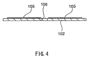
- FIG. 4 is a sectional view of the intermediate member 102.
- the intermediate member 102 has, in substantially the center thereof, the space 106 having a capacity that can house the IC device 104.
- the space 106 is the through hole formed by cutting or boring in the intermediate member 102.
- the conductive layer that is the antenna 105 is formed on the intermediate member 102.
- the thickness of the antenna 105 is enhanced for easy understanding, but actually, the thickness is almost negligible because the antenna can be formed by etching or printing.
- FIG. 5 is an enlarged sectional view of a state in which the front surface member 101, the intermediate member 102, and the rear surface member 103 are bonded to complete the game card 10, with the IC device 104 and portions therearound being enlarged.
- An adhesive layer 501 such as an adhesive is provided between the front surface member 101 and the intermediate member 102 so that the front surface member 101 and the intermediate member 102 do not easily peel.
- the conductive layer that is the antenna 105 is previously formed on one surface (an upper surface in FIG. 5) of the intermediate member 102 by printing or the like.
- the IC device 104 is housed in the space 106 formed in the intermediate member 102 so as to be completely housed in the intermediate member 102 so that the IC device 104 does not push up the front surface member 101 and the rear surface member 103.
- An adhesive layer 501 such as an adhesive is also provided between the rear surface member 103 and the intermediate member 102 so that the rear surface member 103 and the intermediate member 102 do not easily peel.
- the front surface member 101, the intermediate member 102, and the rear surface member 103 are integrated to complete the game card 10.
- FIG. 6 shows electromagnetic waves that the reader/writer 201 generates when reading the game card 10 placed on the game table 20.
- the reader/writer 201 generates electromagnetic waves of high frequency (for example, 880 MHz to 2.45 GHz) for reading the game card 10, and emits the electromagnetic waves 601 from an antenna (an electrode) 600 on the side of the reader/writer 201.
- the emitted electromagnetic waves are received by the antenna 105 of the game card 10 and supplied to the IC device 104 as electric power.
- the game card 10 receives the electromagnetic waves emitted from the reader/writer 201.
- the IC device 104 demodulates the received electromagnetic waves, recognizes a command or a request from the reader/writer 201, performs processing according thereto, and transmits data to the reader/writer 201 according to the request.
- the game card 10 transmits data (in this embodiment, authentication information) to the reader/writer 201
- data in this embodiment, authentication information
- the IC device 104 can modulate, by switching internal impedance, the electromagnetic waves reflected from the antenna of the game card 10, and transmit data from the game card 10 to the reader/writer 201.
- the game card 10 according to the second embodiment is constituted by two layers and different from the game card 10 according to the first embodiment constituted by the three layers.
- FIG. 7 is an exploded perspective view of the game card 10 according to the embodiment.
- the shown game card 10 includes a front surface member 701 on which a front surface (marks, numerals, pictures, or the like) of the card is printed, a rear surface member 702 that is a plate member on which an antenna 704 that is antenna means is provided by printing, in which a space 705 that is a housing space for housing an IC device 703 is formed, and on which a rear surface (patterns or pictures common to all cards) of the card is printed, and the IC device 703 that is circuit means stored in the above described space 705 and electrically connected to the antenna 704.
- the front surface member 701 and the rear surface member 702 are plate members of the size of the card, and made of appropriately strong material, for example, resin such as plastic or cardboard.
- the front surface member 701 and the rear surface member 702 need not to be made of the same material.
- the space 705 formed in the rear surface member 702 is a recess that can house the IC device 703, and thus the rear surface member 702 needs to have at least the same thickness as or a larger thickness than the IC device 703.
- the IC device 703 is an electronic component designed to execute functions of processing, storing, and controlling input/output, and has a function of providing stored information to a reader/writer 201 according to a request from the reader/writer 201.
- the IC device 703 needs not to be constituted by one chip, but may have a configuration in which a plurality of ICs or other electronic components are provided on a circuit board.
- the IC device 703 is stored in the space 705 formed in substantially the center of the rear surface member 702, and electrically connected to the antenna 704.
- the space 705 needs not to be formed in substantially the center of the rear surface member 702, but may be formed in any spot in the rear surface member.
- the space 705 may be formed in any of four corners of the rear surface member 702.
- the space 705 may have any shape as long as the space can house the IC device 703, and needs not have the same shape as the IC device 703.
- the antenna 704 is a member like the antenna 105 according to the first embodiment, and a conductive layer or a film formed on an inner surface of the rear surface member 702.
- the antenna 704 is provided by, for example, printing on the rear surface member 702 with conductive ink, or forming a conductive layer on the front surface of the rear surface member 702 by a technique (vapor deposition or spattering) that can replace the printing.
- the antenna 704 may be formed on an inner surface of the front surface member 701.
- Pasted indium oxide, ITO (Indium Tin Oxide), or the like is used as conductive ink for forming the antenna 704 to provide the antenna 704 formed of a transparent conductive layer or film.
- the antenna 704 formed of such a transparent conductive layer or film is used, the antenna 704 does not appear from a section when the game card 10 is torn, thereby preventing mistrust or discomfort from being caused to a player.
- the antenna 704 serves to transmit and receive signals between the reader/writer 201 and the IC device 703, and convert a carrier wave from the reader/writer 201 to electric power to supply the electric power to the IC device 703.
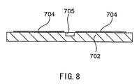
- FIG. 8 is a sectional view of the rear surface member 702.
- the rear surface member 702 has, in substantially the center thereof, the space 705 having a capacity that can house the IC device 703.
- the space 705 is the recess formed by pressing the rear surface member 702.
- the conductive layer that is the antenna 704 is formed on one surface (a surface that is not exposed in the game card 10) of the rear surface member 702.
- the thickness of the antenna 704 is enhanced for easy understanding, but actually, the antenna is formed by etching or printing and the thickness is almost negligible.
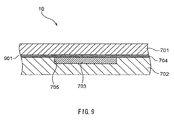
- FIG. 9 is an enlarged sectional view of a state in which the front surface member 701 and the rear surface member 702 are bonded to complete the game card 10, with the IC device 703 and portions therearound being enlarged.
- An adhesive layer 901 such as an adhesive is provided between the front surface member 701 and the rear surface member 702 so that the front surface member 701 and the rear surface member 702 do not easily peel. Thus, the front surface member 101 and the rear surface member 702 are integrated to complete the game card 10.
- the conductive layer that is the antenna 704 is previously formed on one surface (an upper surface in FIG. 9) of the rear surface member 702 by printing or the like.
- the IC device 703 is housed in the space 705 formed in the rear surface member 702 so as to be completely housed in the rear surface member 702 so that the IC device 703 does not push up the front surface member 701 and the rear surface member 702.
- the antenna 704 and the space 705 are provided in the rear surface member 702, but the present invention holds even if the antenna 704 and the space 705 are provided in the front surface member 701.
- a reading operation of the game card 10 according to the second embodiment by the reader/writer 201 is the same as the game card 10 according to the first embodiment, and thus the description thereof will be omitted.
- the game card including the IC device can be formed into a completely flat shape.
- the game cards can be handled in completely the same manner as cards including no IC device even in stacking or shuffling.
- the card is flat without bulging caused by the IC device, and thus even if strong pressure is applied to the card (for example, if the cards are stacked and hit on the table, or the card is pressed on the table with a casino chip or the like being placed on the card), the pressure is not concentrated on the IC device, thereby significantly reducing the possibility of damage to the IC device.
Landscapes
- Engineering & Computer Science (AREA)
- Computer Hardware Design (AREA)
- Microelectronics & Electronic Packaging (AREA)
- Physics & Mathematics (AREA)
- General Physics & Mathematics (AREA)
- Theoretical Computer Science (AREA)
- Multimedia (AREA)
- Credit Cards Or The Like (AREA)
- Pinball Game Machines (AREA)
Abstract
Description
- The present disclosure relates to subject matters contained in
Japanese Patent Application No. 2005-93671 filed on March 29, 2005 - The present invention relates to a game card, and more particularly to a game card from which data can be read by a reading device such as an IC card reader/writer.
- Many of games that have been enjoying popularity use game cards. Such games include card games such as poker and black jack, and trading games using trading cards. Such games are sometimes played in recreation halls such as casinos, betting money or game values valid only in the recreation halls.
- Imprudent players sometimes cheat at games using the game cards. For example, "switching" is often performed to previously prepare game cards of the same type as game cards used in a recreation hall, and switch the game cards dealt on a game table by a dealer so as to be in favor of a player him/herself. An imprudent player thus freely controls development of the game to obtain a large amount of payoff.
- Such cheating is disadvantageous for the recreation hall because of loss of a large amount of payoff, and also for other honest players because of loss of interest.
- Thus, management of a recreation hall proposes a technique of embedding an IC device (a resonant tag) having a proximity communication function in a game card and distinguishing between a normal game card and an unfair game card placed by the "switching" in order to prevent cheating by the "switching" (for example,
Japanese Patent Laid-Open No. 2004-213276 - A conventional game card including an IC device is such that a coil-shaped antenna is connected to the IC device, which is packed with plastic or paper. In this case, a thickness of the game card is relatively larger than a general game card, and thus the card cannot be practically used.
- In casinos or the like, cards are generally torn after the finish of a game. When a conventional card including a coil-shaped antenna is torn, the coil-shaped antenna appears and a tag is found to be embedded in the card, which may cause discomfort to a player.
- The present invention provides a game card including an IC device and an antenna that is hard to be found when the card is torn to be discarded.
- A first aspect of the present invention proposes a game card that stores data readable by a reading device having an antenna that emits electromagnetic waves.
- This game card includes circuit means (for example, an IC device) for transmitting and receiving data according to a request from the reading device, a plate member (for example, an intermediate member or a rear surface member) having a housing space (for example, a space) for housing the circuit means, and antenna means (for example, an antenna or an antenna pattern) provided on the plate member and connected to the circuit means, the antenna means being a conductive layer provided on the plate member.
- In the game card, the antenna means may be formed by printing with conductive ink. Further, white or transparent conducive ink may be used to provide a game card including an antenna that is hard to be found by a player.
- The present invention provides the game card including the antenna that is hard to be found when the card is torn to be discarded.
-
- FIG. 1 is a perspective view of an appearance of a game table;
- FIG. 2 is a block diagram of a function of the game table;
- FIG. 3 is an exploded perspective view of a game card according to a first embodiment;
- FIG. 4 is a sectional view of an intermediate member according to the first embodiment;
- FIG. 5 is a sectional view of an enlarged portion of the game card according to the first embodiment;
- FIG. 6 shows electromagnetic waves that a reader/writer generates when reading the game card;
- FIG. 7 is an exploded perspective view of a game card according to a second embodiment;
- FIG. 8 is a sectional view of a rear surface member according to the second embodiment; and
- FIG. 9 is a sectional view of an enlarged portion of the game card according to the second embodiment.
- The accompanying drawings, which are incorporated in and constitute apart of the specification, illustrate embodiments of the invention, and together with the general description given above and the detailed description of the embodiments given below, serve to explain the principles of the invention.
- Now, embodiments according to the present invention will be described in detail with reference to the drawings.
- First, a game table on which a game card according to the embodiments will be described. FIG. 1 is a perspective view of an appearance of the game table on which the game card according to the embodiments is used.
- The game table 20 according to the embodiments having a table surface on which
game cards 10 are placed is a tool or a facility for a game using the game cards. - In the embodiments, a
dealer 30 and a plurality ofplayers 40 stand or sit face-to-face around the game table 20 for a game. - The
game cards 10 are dealt from a pile by thedealer 30 to thedealer 30 and theplayers 40 and placed on the game table 20. Theplayers 40 take thegame cards 10 in the hands, look at details of thegame cards 10, and sometimes request thedealer 30 to replace thegame cards 10. Thedealer 30 replaces thegame cards 10 according to the request of the players. - Switching of the
game cards 10 that is cheating is likely to be performed, for example, when theplayers 40 take thegame cards 10 to confirm the details of the cards as described above. - FIG. 2 is a block diagram of a function showing a main internal configuration of the game table 20. In the game table 20, a plurality of reader/
writers 201, acontrol device 202 connected to the reader/writers 201, and adisplay device 203 connected to thecontrol device 202 are provided in the game table 20 for reading thegame cards 10 placed on the game table 20. - The
reader 201 that is a reading device reads information (in this example, authentication information) stored in thegame card 10 when thegame card 10 is placed in a reading range, and outputs read information to thecontrol device 202. The reader is herein referred to as a "reader/writer", which does not mean that a writing function is always necessary. A device having at least a function of reading data stored in thegame card 10 corresponds to the "reader/writer" in the specification. - The
game card 10 stores the authentication information. The authentication information is data indicating that thegame card 10 is allowed to be used in the game, for example, predetermined N-bite numbers. The authentication information may be different among or common to thegame cards 10. For example, all of the 53game cards 10 that constitute a set of playing cards may store common authentication information. The 53game cards 10 may store different authentication information so as to be distinguishable among the kinds of the cards (for example, A (ace) of spade, 2 of heart, or the like). - The
control device 202 stores the authentication information of thegame cards 10 that are allowed to be used. When receiving the read authentication information from the reader/writer 201, thecontrol device 202 compares the authentication information read by the reader/writer 201 and the stored authentication information, and determines whether the read authentication information is information of thegame card 10 that is allowed to be used. Thecontrol device 202 outputs a determination result to adisplay device 203. - The
display device 203 displays the determination result as an image, and thedealer 30 can learn whether thegame card 10 used on the game table 20 is thegame card 10 that is allowed to be used, that is, whether an unfair game card is not used by switching or the like. - The
display device 203 needs not to be provided in the game table 20, but may be provided in an environment remote from the game table 20, for example, a monitoring room in a casino hall. The image needs not to be displayed as long as an occurrence of cheating can be notified, and notifying means (a lamp or a speaker) may be provided instead of thedisplay device 203. - Next, a configuration example of the
game card 10 according to this embodiment will be described with reference to FIGS. 3 to 5. - FIG. 3 is an exploded perspective view of the
game card 10. The showngame card 10 includes afront surface member 101 on which a front surface (marks, numerals, pictures, or the like) of the card is printed, anintermediate member 102 that is a plate member on which anantenna 105 that is antenna means is provided by printing, and in which aspace 106 that is a housing space for housing anIC device 104 is formed, arear surface member 103 on which a rear surface (patterns or pictures common to all cards) of the card is printed, and theIC device 104 that is circuit means stored in thespace 106 and electrically connected to theantenna 105. - The
front surface member 101, theintermediate member 102, and therear surface member 103 are plate members of the size of the card, and made of appropriately strong material, for example, resin such as plastic or cardboard. Thefront surface member 101, theintermediate member 102, and therear surface member 103 needs not to be made of the same material. - The
space 106 formed in theintermediate member 102 is a through hole that can house theIC device 104, and thus theintermediate member 102 needs to have at least the same thickness as or a larger thickness than theIC device 104. - The
IC device 104 is an electronic component designed to execute functions of processing, storing, and controlling input/output, and has a function of providing stored information to the reader/writer 201 according to a request from the reader/writer 201. TheIC device 104 needs not to be constituted by one chip, but may have a configuration in which a plurality of ICs or other electronic components are provided on a circuit board. - The
IC device 104 is stored in thespace 106 formed in substantially the center of theintermediate member 102, and electrically connected to theantenna 105. Thespace 106 needs not to be formed in substantially the center of theintermediate member 102, but may be formed in any spot in the intermediate member. For example, thespace 106 may be formed in any of four corners of theintermediate member 102. Thespace 106 may have any shape as long as the space can house theIC device 104, and needs not have the same shape as the IC device. - The
antenna 105 is a conductive layer formed on the front surface of theintermediate member 102. Theantenna 105 may be provided on at least one surface of theintermediate member 102. Theantenna 105 is provided by, for example, printing on theintermediate member 102 with conductive ink, or forming a conductive layer on the front surface of theintermediate member 102 by a technique (vapor deposition or spattering) that can replace the printing. When a configuration electrically connectable to theIC device 104 is used, theantenna 105 may be formed on thefront surface member 101 and/or therear surface member 103. - Pasted indium oxide, ITO (Indium Tin Oxide), or the like is used as conductive ink for forming the
antenna 105 to provide theantenna 105 formedof a transparent conductive layer. When theantenna 105 formed of such a transparent conductive layer is used, theantenna 105 does not appear from a section when thegame card 10 is torn, thereby preventing mistrust or discomfort from being caused to a player. - The
antenna 105 serves to transmit and receive signals between the reader/writer 201 and theIC device 104, and convert a carrier wave from the reader/writer 201 to electric power to supply the electric power to theIC device 104. - FIG. 4 is a sectional view of the
intermediate member 102. Theintermediate member 102 has, in substantially the center thereof, thespace 106 having a capacity that can house theIC device 104. Thespace 106 is the through hole formed by cutting or boring in theintermediate member 102. - The conductive layer that is the
antenna 105 is formed on theintermediate member 102. In FIG. 4, the thickness of theantenna 105 is enhanced for easy understanding, but actually, the thickness is almost negligible because the antenna can be formed by etching or printing. - FIG. 5 is an enlarged sectional view of a state in which the
front surface member 101, theintermediate member 102, and therear surface member 103 are bonded to complete thegame card 10, with theIC device 104 and portions therearound being enlarged. - An
adhesive layer 501 such as an adhesive is provided between thefront surface member 101 and theintermediate member 102 so that thefront surface member 101 and theintermediate member 102 do not easily peel. - The conductive layer that is the
antenna 105 is previously formed on one surface (an upper surface in FIG. 5) of theintermediate member 102 by printing or the like. TheIC device 104 is housed in thespace 106 formed in theintermediate member 102 so as to be completely housed in theintermediate member 102 so that theIC device 104 does not push up thefront surface member 101 and therear surface member 103. - An
adhesive layer 501 such as an adhesive is also provided between therear surface member 103 and theintermediate member 102 so that therear surface member 103 and theintermediate member 102 do not easily peel. Thus, thefront surface member 101, theintermediate member 102, and therear surface member 103 are integrated to complete thegame card 10. - Next, an operation example of the
game card 10 will be described. - FIG. 6 shows electromagnetic waves that the reader/
writer 201 generates when reading thegame card 10 placed on the game table 20. - The reader/
writer 201 generates electromagnetic waves of high frequency (for example, 880 MHz to 2.45 GHz) for reading thegame card 10, and emits theelectromagnetic waves 601 from an antenna (an electrode) 600 on the side of the reader/writer 201. The emitted electromagnetic waves are received by theantenna 105 of thegame card 10 and supplied to theIC device 104 as electric power. - The
game card 10 receives the electromagnetic waves emitted from the reader/writer 201. TheIC device 104 demodulates the received electromagnetic waves, recognizes a command or a request from the reader/writer 201, performs processing according thereto, and transmits data to the reader/writer 201 according to the request. - When the
game card 10 transmits data (in this embodiment, authentication information) to the reader/writer 201, a so-called back scattering coupling method can be used. Thus, theIC device 104 can modulate, by switching internal impedance, the electromagnetic waves reflected from the antenna of thegame card 10, and transmit data from thegame card 10 to the reader/writer 201. - Next, a configuration example of a
game card 10 according to a second embodiment will be described with reference to FIGS. 7 to 9. Thegame card 10 according to the second embodiment is constituted by two layers and different from thegame card 10 according to the first embodiment constituted by the three layers. - FIG. 7 is an exploded perspective view of the
game card 10 according to the embodiment. The showngame card 10 includes afront surface member 701 on which a front surface (marks, numerals, pictures, or the like) of the card is printed, arear surface member 702 that is a plate member on which anantenna 704 that is antenna means is provided by printing, in which aspace 705 that is a housing space for housing anIC device 703 is formed, and on which a rear surface (patterns or pictures common to all cards) of the card is printed, and theIC device 703 that is circuit means stored in the above describedspace 705 and electrically connected to theantenna 704. - The
front surface member 701 and therear surface member 702 are plate members of the size of the card, and made of appropriately strong material, for example, resin such as plastic or cardboard. Thefront surface member 701 and therear surface member 702 need not to be made of the same material. - The
space 705 formed in therear surface member 702 is a recess that can house theIC device 703, and thus therear surface member 702 needs to have at least the same thickness as or a larger thickness than theIC device 703. - Like the
IC device 104 according to the first embodiment, theIC device 703 is an electronic component designed to execute functions of processing, storing, and controlling input/output, and has a function of providing stored information to a reader/writer 201 according to a request from the reader/writer 201. TheIC device 703 needs not to be constituted by one chip, but may have a configuration in which a plurality of ICs or other electronic components are provided on a circuit board. - The
IC device 703 is stored in thespace 705 formed in substantially the center of therear surface member 702, and electrically connected to theantenna 704. Thespace 705 needs not to be formed in substantially the center of therear surface member 702, but may be formed in any spot in the rear surface member. For example, thespace 705 may be formed in any of four corners of therear surface member 702. Thespace 705 may have any shape as long as the space can house theIC device 703, and needs not have the same shape as theIC device 703. - The
antenna 704 is a member like theantenna 105 according to the first embodiment, and a conductive layer or a film formed on an inner surface of therear surface member 702. Theantenna 704 is provided by, for example, printing on therear surface member 702 with conductive ink, or forming a conductive layer on the front surface of therear surface member 702 by a technique (vapor deposition or spattering) that can replace the printing. When a configuration electrically connectable to theIC device 703 is used, theantenna 704 may be formed on an inner surface of thefront surface member 701. - Pasted indium oxide, ITO (Indium Tin Oxide), or the like is used as conductive ink for forming the
antenna 704 to provide theantenna 704 formed of a transparent conductive layer or film. When theantenna 704 formed of such a transparent conductive layer or film is used, theantenna 704 does not appear from a section when thegame card 10 is torn, thereby preventing mistrust or discomfort from being caused to a player. - The
antenna 704 serves to transmit and receive signals between the reader/writer 201 and theIC device 703, and convert a carrier wave from the reader/writer 201 to electric power to supply the electric power to theIC device 703. - FIG. 8 is a sectional view of the
rear surface member 702. Therear surface member 702 has, in substantially the center thereof, thespace 705 having a capacity that can house theIC device 703. Thespace 705 is the recess formed by pressing therear surface member 702. - The conductive layer that is the
antenna 704 is formed on one surface (a surface that is not exposed in the game card 10) of therear surface member 702. In FIG. 8, the thickness of theantenna 704 is enhanced for easy understanding, but actually, the antenna is formed by etching or printing and the thickness is almost negligible. - FIG. 9 is an enlarged sectional view of a state in which the
front surface member 701 and therear surface member 702 are bonded to complete thegame card 10, with theIC device 703 and portions therearound being enlarged. - An
adhesive layer 901 such as an adhesive is provided between thefront surface member 701 and therear surface member 702 so that thefront surface member 701 and therear surface member 702 do not easily peel. Thus, thefront surface member 101 and therear surface member 702 are integrated to complete thegame card 10. - The conductive layer that is the
antenna 704 is previously formed on one surface (an upper surface in FIG. 9) of therear surface member 702 by printing or the like. TheIC device 703 is housed in thespace 705 formed in therear surface member 702 so as to be completely housed in therear surface member 702 so that theIC device 703 does not push up thefront surface member 701 and therear surface member 702. - In the above described configuration example, the
antenna 704 and thespace 705 are provided in therear surface member 702, but the present invention holds even if theantenna 704 and thespace 705 are provided in thefront surface member 701. - A reading operation of the
game card 10 according to the second embodiment by the reader/writer 201 is the same as thegame card 10 according to the first embodiment, and thus the description thereof will be omitted. - According to the present invention, the game card including the IC device can be formed into a completely flat shape. Thus, the game cards can be handled in completely the same manner as cards including no IC device even in stacking or shuffling.
- Further, the card is flat without bulging caused by the IC device, and thus even if strong pressure is applied to the card (for example, if the cards are stacked and hit on the table, or the card is pressed on the table with a casino chip or the like being placed on the card), the pressure is not concentrated on the IC device, thereby significantly reducing the possibility of damage to the IC device.
- Additional advantages and modifications will readily occur to those skilled in the art. Therefore, the invention in its broader aspects is not limited to the specific details or representative embodiments shown and described herein. Accordingly, various modification may be made without departing from the spirit or scope of the general inventive concept as defined by the appended claims and their equivalents.
Claims (6)
- A game card that stores data readable by a reading device that emits electromagnetic waves, characterized in that said game card comprises:circuit means for transmitting and receiving data according to a request from the reading device;a plate member having a housing space for housing said circuit means; andantenna means provided on said plate member and connected to said circuit means,wherein said antenna means is a conductive layer provided on said plate member.
- The game card according to claim 1, wherein said antenna means is formed by providing a conductive material on said plate member.
- The game card according to claim 2, wherein said antenna means is formed by printing with conductive ink.
- The game card according to claim 2, wherein said antenna means is formed by depositing conductive material on said plate member.
- The game card according to claim 2, wherein said antenna means is formed by spattering conductive material on said plate member.
- The game card according to any one of claims 1 to 5, wherein said antenna means is transparent conductive layers.
Applications Claiming Priority (1)
| Application Number | Priority Date | Filing Date | Title |
|---|---|---|---|
| JP2005093671A JP2006271596A (en) | 2005-03-29 | 2005-03-29 | Game cards |
Publications (2)
| Publication Number | Publication Date |
|---|---|
| EP1713027A2 true EP1713027A2 (en) | 2006-10-18 |
| EP1713027A3 EP1713027A3 (en) | 2008-06-11 |
Family
ID=36933349
Family Applications (1)
| Application Number | Title | Priority Date | Filing Date |
|---|---|---|---|
| EP06006239A Withdrawn EP1713027A3 (en) | 2005-03-29 | 2006-03-27 | Game card with an IC device and an antenna |
Country Status (3)
| Country | Link |
|---|---|
| US (1) | US20060219797A1 (en) |
| EP (1) | EP1713027A3 (en) |
| JP (1) | JP2006271596A (en) |
Cited By (2)
| Publication number | Priority date | Publication date | Assignee | Title |
|---|---|---|---|---|
| DE102007007022A1 (en) * | 2007-02-08 | 2008-08-21 | Bruno Ernst | Playing card for e.g. poker game, has electronically readable identification device for storing information that is used to uniquely identify card, and reading device of table reading information, which includes characteristic and value |
| US8894495B1 (en) | 2014-01-08 | 2014-11-25 | David Saul Vogel | Multi-part system for deploying near field communications in order to facilitate the ability of a visually-impaired person to ascertain the identity of a playing card |
Families Citing this family (8)
| Publication number | Priority date | Publication date | Assignee | Title |
|---|---|---|---|---|
| JP2006277178A (en) * | 2005-03-29 | 2006-10-12 | Aruze Corp | Game cards |
| JP2008246104A (en) * | 2007-03-30 | 2008-10-16 | Angel Shoji Kk | Game card incorporating rfid and its manufacturing method |
| KR101171920B1 (en) * | 2010-01-14 | 2012-08-08 | 박기업 | Card game device |
| DE112010005633T5 (en) * | 2010-07-09 | 2013-03-28 | Hewlett-Packard Development Co., L.P. | RFID antenna and 2D barcode |
| US9662562B2 (en) | 2010-10-18 | 2017-05-30 | Angel Playing Cards Co., Ltd. | Table game system |
| JP2014003989A (en) * | 2010-10-18 | 2014-01-16 | Angel Playing Cards Co Ltd | Card reader and table game system |
| JP2015128458A (en) | 2012-04-23 | 2015-07-16 | エンゼルプレイングカード株式会社 | card reader and table game system |
| EP3269558B1 (en) | 2016-07-15 | 2019-01-23 | Cartamundi Turnhout N.V. | A manufacturing process for a laminated paper product |
Citations (3)
| Publication number | Priority date | Publication date | Assignee | Title |
|---|---|---|---|---|
| FR2775196A1 (en) | 1998-02-26 | 1999-08-27 | Gemplus Sca | Playing card/gambling token/ticket identification |
| JP2003085510A (en) * | 2001-09-13 | 2003-03-20 | Dainippon Printing Co Ltd | Paper IC card having contactless communication function, paper IC card base material, and game paper IC card |
| WO2003096384A2 (en) | 2002-05-07 | 2003-11-20 | Reveo, Inc. | Conductive ink |
Family Cites Families (26)
| Publication number | Priority date | Publication date | Assignee | Title |
|---|---|---|---|---|
| DE4431605C2 (en) * | 1994-09-05 | 1998-06-04 | Siemens Ag | Method for producing a chip card module for contactless chip cards |
| JPH08216573A (en) * | 1995-02-09 | 1996-08-27 | Hitachi Chem Co Ltd | Ic card |
| FR2743649B1 (en) * | 1996-01-17 | 1998-04-03 | Gemplus Card Int | CONTACTLESS ELECTRONIC MODULE, ELECTRONIC LABEL CARD INCORPORATING THE SAME, AND METHODS OF MAKING SAME |
| US5955949A (en) * | 1997-08-18 | 1999-09-21 | X-Cyte, Inc. | Layered structure for a transponder tag |
| JPH11234163A (en) * | 1998-02-10 | 1999-08-27 | Sony Corp | IC card and IC card system |
| US6010131A (en) * | 1998-07-13 | 2000-01-04 | George C. Matteson Co. Inc. | Machine for voiding playing cards |
| JP3649374B2 (en) * | 1998-11-30 | 2005-05-18 | ソニー株式会社 | Antenna device and card-like storage medium |
| US6460848B1 (en) * | 1999-04-21 | 2002-10-08 | Mindplay Llc | Method and apparatus for monitoring casinos and gaming |
| DE20017736U1 (en) * | 2000-10-16 | 2002-02-28 | Euro Event Marketing Consulting GmbH, 44319 Dortmund | transponder card |
| US6558528B1 (en) * | 2000-12-20 | 2003-05-06 | Lifescan, Inc. | Electrochemical test strip cards that include an integral dessicant |
| FR2826154B1 (en) * | 2001-06-14 | 2004-07-23 | A S K | CHIP CARD WITHOUT CONTACT WITH AN ANTENNA SUPPORT AND CHIP SUPPORT OF FIBROUS MATERIAL |
| JP4397553B2 (en) * | 2001-09-07 | 2010-01-13 | 株式会社ユニバーサルエンターテインメント | Card game monitoring system and card game table |
| KR20030076274A (en) * | 2002-03-18 | 2003-09-26 | 도레 엔지니아린구 가부시키가이샤 | Non-contact id card and the method for producing thereof |
| US6677906B2 (en) * | 2002-04-17 | 2004-01-13 | Dell Products L.P. | Glass antenna for laptop computers |
| FR2844621A1 (en) * | 2002-09-13 | 2004-03-19 | A S K | Method for manufacturing without contact or hybrid integrated circuit card, comprises application of two thermoplastic layers under temperature and pressure followed by two hot pressed plastic layers |
| EP1585056A4 (en) * | 2002-12-27 | 2006-04-26 | Aruze Corp | CARD HOLDER WITH INTEGRATED RESONANCE LABEL, PROCESS FOR PRODUCING THE CARD HOLDER, AND DEVICE IDENTIFYING AN OBJECT |
| US7575234B2 (en) * | 2003-04-17 | 2009-08-18 | Bally Gaming, Inc. | Wireless monitoring of playing cards and/or wagers in gaming |
| US7806408B2 (en) * | 2003-06-18 | 2010-10-05 | Thwartpoker, Inc. | Table with computer for playing card selection game |
| JP2005033500A (en) * | 2003-07-14 | 2005-02-03 | Hitachi Ltd | Antenna coil design apparatus and design method |
| US20050054408A1 (en) * | 2003-09-08 | 2005-03-10 | Steil Rolland Nicholas | Smart casino live card playing system and method |
| JP2005093867A (en) * | 2003-09-19 | 2005-04-07 | Seiko Epson Corp | Semiconductor device and manufacturing method thereof |
| JP3982476B2 (en) * | 2003-10-01 | 2007-09-26 | ソニー株式会社 | Communications system |
| AU2005254570A1 (en) * | 2004-06-15 | 2005-12-29 | Real Time Graphics, Llc | Automated playing card identification and tracking system |
| JP2006167329A (en) * | 2004-12-20 | 2006-06-29 | Aruze Corp | Gaming chips |
| US7689195B2 (en) * | 2005-02-22 | 2010-03-30 | Broadcom Corporation | Multi-protocol radio frequency identification transponder tranceiver |
| US20060205508A1 (en) * | 2005-03-14 | 2006-09-14 | Original Deal, Inc. | On-line table gaming with physical game objects |
-
2005
- 2005-03-29 JP JP2005093671A patent/JP2006271596A/en active Pending
-
2006
- 2006-03-14 US US11/374,474 patent/US20060219797A1/en not_active Abandoned
- 2006-03-27 EP EP06006239A patent/EP1713027A3/en not_active Withdrawn
Patent Citations (3)
| Publication number | Priority date | Publication date | Assignee | Title |
|---|---|---|---|---|
| FR2775196A1 (en) | 1998-02-26 | 1999-08-27 | Gemplus Sca | Playing card/gambling token/ticket identification |
| JP2003085510A (en) * | 2001-09-13 | 2003-03-20 | Dainippon Printing Co Ltd | Paper IC card having contactless communication function, paper IC card base material, and game paper IC card |
| WO2003096384A2 (en) | 2002-05-07 | 2003-11-20 | Reveo, Inc. | Conductive ink |
Cited By (2)
| Publication number | Priority date | Publication date | Assignee | Title |
|---|---|---|---|---|
| DE102007007022A1 (en) * | 2007-02-08 | 2008-08-21 | Bruno Ernst | Playing card for e.g. poker game, has electronically readable identification device for storing information that is used to uniquely identify card, and reading device of table reading information, which includes characteristic and value |
| US8894495B1 (en) | 2014-01-08 | 2014-11-25 | David Saul Vogel | Multi-part system for deploying near field communications in order to facilitate the ability of a visually-impaired person to ascertain the identity of a playing card |
Also Published As
| Publication number | Publication date |
|---|---|
| US20060219797A1 (en) | 2006-10-05 |
| EP1713027A3 (en) | 2008-06-11 |
| JP2006271596A (en) | 2006-10-12 |
Similar Documents
| Publication | Publication Date | Title |
|---|---|---|
| EP1713026A1 (en) | Game card | |
| EP1672567A1 (en) | Game chip | |
| US10155152B2 (en) | Intelligent game system including intelligent foldable three-dimensional terrain | |
| US20060219797A1 (en) | Game card | |
| US20040207156A1 (en) | Wireless monitoring of playing cards and/or wagers in gaming | |
| KR101185963B1 (en) | Rfid reader for use in casinochip tray | |
| CN1867383A (en) | Electronic educational game set having communicating elements with a radio-frequency tag | |
| JP2002018098A (en) | Game device | |
| CN101960467A (en) | Light guide device, non-contact communication medium reading and writing device and electronic equipment | |
| US20070052167A1 (en) | Radio frequency identification (RFID) poker table | |
| WO2009026110A2 (en) | Table with indicators and smart card holder for automated gaming system and gaming cards | |
| JP4357010B2 (en) | Game machine | |
| JP2008114040A (en) | Discrete type prize | |
| EP1672602A1 (en) | Game chip | |
| US20090181741A1 (en) | Card game apparatus with card displays | |
| JP3935102B2 (en) | Game device | |
| CN207817755U (en) | Trading Cards with Voice Recording and Playback | |
| JP2002126301A (en) | Board case for game machine | |
| US12434131B2 (en) | Gaming hardware device, a board game kit and related control method | |
| TWI251503B (en) | Game image display control device, game image display control method, and game image display control program | |
| JP4201787B2 (en) | Game machine, storage medium, and game machine body | |
| JP2005028104A (en) | Game system using game card equipped with image display screen | |
| US20060178210A1 (en) | Game playing device | |
| AU2013205817B2 (en) | Gaming table for use with gaming chips incorporating an electronic microchip | |
| JP3100869U (en) | Arm type card game machine |
Legal Events
| Date | Code | Title | Description |
|---|---|---|---|
| PUAI | Public reference made under article 153(3) epc to a published international application that has entered the european phase |
Free format text: ORIGINAL CODE: 0009012 |
|
| AK | Designated contracting states |
Kind code of ref document: A2 Designated state(s): AT BE BG CH CY CZ DE DK EE ES FI FR GB GR HU IE IS IT LI LT LU LV MC NL PL PT RO SE SI SK TR |
|
| AX | Request for extension of the european patent |
Extension state: AL BA HR MK YU |
|
| PUAL | Search report despatched |
Free format text: ORIGINAL CODE: 0009013 |
|
| AK | Designated contracting states |
Kind code of ref document: A3 Designated state(s): AT BE BG CH CY CZ DE DK EE ES FI FR GB GR HU IE IS IT LI LT LU LV MC NL PL PT RO SE SI SK TR |
|
| AX | Request for extension of the european patent |
Extension state: AL BA HR MK YU |
|
| 17P | Request for examination filed |
Effective date: 20080819 |
|
| AKX | Designation fees paid |
Designated state(s): AT BE BG CH CY CZ DE DK EE ES FI FR GB GR HU IE IS IT LI LT LU LV MC NL PL PT RO SE SI SK TR |
|
| 17Q | First examination report despatched |
Effective date: 20100112 |
|
| STAA | Information on the status of an ep patent application or granted ep patent |
Free format text: STATUS: THE APPLICATION IS DEEMED TO BE WITHDRAWN |
|
| 18D | Application deemed to be withdrawn |
Effective date: 20121122 |