EP1712772A2 - Hybrid vehicle and engine therefor - Google Patents
Hybrid vehicle and engine therefor Download PDFInfo
- Publication number
- EP1712772A2 EP1712772A2 EP06007703A EP06007703A EP1712772A2 EP 1712772 A2 EP1712772 A2 EP 1712772A2 EP 06007703 A EP06007703 A EP 06007703A EP 06007703 A EP06007703 A EP 06007703A EP 1712772 A2 EP1712772 A2 EP 1712772A2
- Authority
- EP
- European Patent Office
- Prior art keywords
- air
- intake pipe
- engine
- cleaner
- fuel
- Prior art date
- Legal status (The legal status is an assumption and is not a legal conclusion. Google has not performed a legal analysis and makes no representation as to the accuracy of the status listed.)
- Withdrawn
Links
Images




Classifications
-
- F—MECHANICAL ENGINEERING; LIGHTING; HEATING; WEAPONS; BLASTING
- F02—COMBUSTION ENGINES; HOT-GAS OR COMBUSTION-PRODUCT ENGINE PLANTS
- F02M—SUPPLYING COMBUSTION ENGINES IN GENERAL WITH COMBUSTIBLE MIXTURES OR CONSTITUENTS THEREOF
- F02M35/00—Combustion-air cleaners, air intakes, intake silencers, or induction systems specially adapted for, or arranged on, internal-combustion engines
- F02M35/16—Combustion-air cleaners, air intakes, intake silencers, or induction systems specially adapted for, or arranged on, internal-combustion engines characterised by use in vehicles
- F02M35/162—Motorcycles; All-terrain vehicles, e.g. quads, snowmobiles; Small vehicles, e.g. forklifts
-
- B—PERFORMING OPERATIONS; TRANSPORTING
- B60—VEHICLES IN GENERAL
- B60K—ARRANGEMENT OR MOUNTING OF PROPULSION UNITS OR OF TRANSMISSIONS IN VEHICLES; ARRANGEMENT OR MOUNTING OF PLURAL DIVERSE PRIME-MOVERS IN VEHICLES; AUXILIARY DRIVES FOR VEHICLES; INSTRUMENTATION OR DASHBOARDS FOR VEHICLES; ARRANGEMENTS IN CONNECTION WITH COOLING, AIR INTAKE, GAS EXHAUST OR FUEL SUPPLY OF PROPULSION UNITS IN VEHICLES
- B60K6/00—Arrangement or mounting of plural diverse prime-movers for mutual or common propulsion, e.g. hybrid propulsion systems comprising electric motors and internal combustion engines
- B60K6/20—Arrangement or mounting of plural diverse prime-movers for mutual or common propulsion, e.g. hybrid propulsion systems comprising electric motors and internal combustion engines the prime-movers consisting of electric motors and internal combustion engines, e.g. HEVs
- B60K6/22—Arrangement or mounting of plural diverse prime-movers for mutual or common propulsion, e.g. hybrid propulsion systems comprising electric motors and internal combustion engines the prime-movers consisting of electric motors and internal combustion engines, e.g. HEVs characterised by apparatus, components or means specially adapted for HEVs
- B60K6/24—Arrangement or mounting of plural diverse prime-movers for mutual or common propulsion, e.g. hybrid propulsion systems comprising electric motors and internal combustion engines the prime-movers consisting of electric motors and internal combustion engines, e.g. HEVs characterised by apparatus, components or means specially adapted for HEVs characterised by the combustion engines
-
- B—PERFORMING OPERATIONS; TRANSPORTING
- B60—VEHICLES IN GENERAL
- B60K—ARRANGEMENT OR MOUNTING OF PROPULSION UNITS OR OF TRANSMISSIONS IN VEHICLES; ARRANGEMENT OR MOUNTING OF PLURAL DIVERSE PRIME-MOVERS IN VEHICLES; AUXILIARY DRIVES FOR VEHICLES; INSTRUMENTATION OR DASHBOARDS FOR VEHICLES; ARRANGEMENTS IN CONNECTION WITH COOLING, AIR INTAKE, GAS EXHAUST OR FUEL SUPPLY OF PROPULSION UNITS IN VEHICLES
- B60K6/00—Arrangement or mounting of plural diverse prime-movers for mutual or common propulsion, e.g. hybrid propulsion systems comprising electric motors and internal combustion engines
- B60K6/20—Arrangement or mounting of plural diverse prime-movers for mutual or common propulsion, e.g. hybrid propulsion systems comprising electric motors and internal combustion engines the prime-movers consisting of electric motors and internal combustion engines, e.g. HEVs
- B60K6/42—Arrangement or mounting of plural diverse prime-movers for mutual or common propulsion, e.g. hybrid propulsion systems comprising electric motors and internal combustion engines the prime-movers consisting of electric motors and internal combustion engines, e.g. HEVs characterised by the architecture of the hybrid electric vehicle
- B60K6/48—Parallel type
-
- B—PERFORMING OPERATIONS; TRANSPORTING
- B60—VEHICLES IN GENERAL
- B60L—PROPULSION OF ELECTRICALLY-PROPELLED VEHICLES; SUPPLYING ELECTRIC POWER FOR AUXILIARY EQUIPMENT OF ELECTRICALLY-PROPELLED VEHICLES; ELECTRODYNAMIC BRAKE SYSTEMS FOR VEHICLES IN GENERAL; MAGNETIC SUSPENSION OR LEVITATION FOR VEHICLES; MONITORING OPERATING VARIABLES OF ELECTRICALLY-PROPELLED VEHICLES; ELECTRIC SAFETY DEVICES FOR ELECTRICALLY-PROPELLED VEHICLES
- B60L50/00—Electric propulsion with power supplied within the vehicle
- B60L50/10—Electric propulsion with power supplied within the vehicle using propulsion power supplied by engine-driven generators, e.g. generators driven by combustion engines
- B60L50/15—Electric propulsion with power supplied within the vehicle using propulsion power supplied by engine-driven generators, e.g. generators driven by combustion engines with additional electric power supply
-
- B—PERFORMING OPERATIONS; TRANSPORTING
- B62—LAND VEHICLES FOR TRAVELLING OTHERWISE THAN ON RAILS
- B62M—RIDER PROPULSION OF WHEELED VEHICLES OR SLEDGES; POWERED PROPULSION OF SLEDGES OR SINGLE-TRACK CYCLES; TRANSMISSIONS SPECIALLY ADAPTED FOR SUCH VEHICLES
- B62M7/00—Motorcycles characterised by position of motor or engine
- B62M7/12—Motorcycles characterised by position of motor or engine with the engine beside or within the driven wheel
-
- F—MECHANICAL ENGINEERING; LIGHTING; HEATING; WEAPONS; BLASTING
- F02—COMBUSTION ENGINES; HOT-GAS OR COMBUSTION-PRODUCT ENGINE PLANTS
- F02M—SUPPLYING COMBUSTION ENGINES IN GENERAL WITH COMBUSTIBLE MIXTURES OR CONSTITUENTS THEREOF
- F02M35/00—Combustion-air cleaners, air intakes, intake silencers, or induction systems specially adapted for, or arranged on, internal-combustion engines
- F02M35/02—Air cleaners
- F02M35/04—Air cleaners specially arranged with respect to engine, to intake system or specially adapted to vehicle; Mounting thereon ; Combinations with other devices
-
- F—MECHANICAL ENGINEERING; LIGHTING; HEATING; WEAPONS; BLASTING
- F02—COMBUSTION ENGINES; HOT-GAS OR COMBUSTION-PRODUCT ENGINE PLANTS
- F02M—SUPPLYING COMBUSTION ENGINES IN GENERAL WITH COMBUSTIBLE MIXTURES OR CONSTITUENTS THEREOF
- F02M35/00—Combustion-air cleaners, air intakes, intake silencers, or induction systems specially adapted for, or arranged on, internal-combustion engines
- F02M35/10—Air intakes; Induction systems
- F02M35/10091—Air intakes; Induction systems characterised by details of intake ducts: shapes; connections; arrangements
-
- B—PERFORMING OPERATIONS; TRANSPORTING
- B60—VEHICLES IN GENERAL
- B60L—PROPULSION OF ELECTRICALLY-PROPELLED VEHICLES; SUPPLYING ELECTRIC POWER FOR AUXILIARY EQUIPMENT OF ELECTRICALLY-PROPELLED VEHICLES; ELECTRODYNAMIC BRAKE SYSTEMS FOR VEHICLES IN GENERAL; MAGNETIC SUSPENSION OR LEVITATION FOR VEHICLES; MONITORING OPERATING VARIABLES OF ELECTRICALLY-PROPELLED VEHICLES; ELECTRIC SAFETY DEVICES FOR ELECTRICALLY-PROPELLED VEHICLES
- B60L2200/00—Type of vehicles
- B60L2200/12—Bikes
-
- B—PERFORMING OPERATIONS; TRANSPORTING
- B60—VEHICLES IN GENERAL
- B60Y—INDEXING SCHEME RELATING TO ASPECTS CROSS-CUTTING VEHICLE TECHNOLOGY
- B60Y2200/00—Type of vehicle
- B60Y2200/10—Road Vehicles
- B60Y2200/12—Motorcycles, Trikes; Quads; Scooters
-
- B—PERFORMING OPERATIONS; TRANSPORTING
- B62—LAND VEHICLES FOR TRAVELLING OTHERWISE THAN ON RAILS
- B62K—CYCLES; CYCLE FRAMES; CYCLE STEERING DEVICES; RIDER-OPERATED TERMINAL CONTROLS SPECIALLY ADAPTED FOR CYCLES; CYCLE AXLE SUSPENSIONS; CYCLE SIDECARS, FORECARS, OR THE LIKE
- B62K2202/00—Motorised scooters
-
- B—PERFORMING OPERATIONS; TRANSPORTING
- B62—LAND VEHICLES FOR TRAVELLING OTHERWISE THAN ON RAILS
- B62K—CYCLES; CYCLE FRAMES; CYCLE STEERING DEVICES; RIDER-OPERATED TERMINAL CONTROLS SPECIALLY ADAPTED FOR CYCLES; CYCLE AXLE SUSPENSIONS; CYCLE SIDECARS, FORECARS, OR THE LIKE
- B62K2204/00—Adaptations for driving cycles by electric motor
-
- F—MECHANICAL ENGINEERING; LIGHTING; HEATING; WEAPONS; BLASTING
- F02—COMBUSTION ENGINES; HOT-GAS OR COMBUSTION-PRODUCT ENGINE PLANTS
- F02B—INTERNAL-COMBUSTION PISTON ENGINES; COMBUSTION ENGINES IN GENERAL
- F02B61/00—Adaptations of engines for driving vehicles or for driving propellers; Combinations of engines with gearing
- F02B61/02—Adaptations of engines for driving vehicles or for driving propellers; Combinations of engines with gearing for driving cycles
-
- Y—GENERAL TAGGING OF NEW TECHNOLOGICAL DEVELOPMENTS; GENERAL TAGGING OF CROSS-SECTIONAL TECHNOLOGIES SPANNING OVER SEVERAL SECTIONS OF THE IPC; TECHNICAL SUBJECTS COVERED BY FORMER USPC CROSS-REFERENCE ART COLLECTIONS [XRACs] AND DIGESTS
- Y02—TECHNOLOGIES OR APPLICATIONS FOR MITIGATION OR ADAPTATION AGAINST CLIMATE CHANGE
- Y02T—CLIMATE CHANGE MITIGATION TECHNOLOGIES RELATED TO TRANSPORTATION
- Y02T10/00—Road transport of goods or passengers
- Y02T10/60—Other road transportation technologies with climate change mitigation effect
- Y02T10/62—Hybrid vehicles
-
- Y—GENERAL TAGGING OF NEW TECHNOLOGICAL DEVELOPMENTS; GENERAL TAGGING OF CROSS-SECTIONAL TECHNOLOGIES SPANNING OVER SEVERAL SECTIONS OF THE IPC; TECHNICAL SUBJECTS COVERED BY FORMER USPC CROSS-REFERENCE ART COLLECTIONS [XRACs] AND DIGESTS
- Y02—TECHNOLOGIES OR APPLICATIONS FOR MITIGATION OR ADAPTATION AGAINST CLIMATE CHANGE
- Y02T—CLIMATE CHANGE MITIGATION TECHNOLOGIES RELATED TO TRANSPORTATION
- Y02T10/00—Road transport of goods or passengers
- Y02T10/60—Other road transportation technologies with climate change mitigation effect
- Y02T10/7072—Electromobility specific charging systems or methods for batteries, ultracapacitors, supercapacitors or double-layer capacitors
Definitions
- the present invention relates to an engine, in particular for a hybrid vehicle and to a hybrid vehicle having an engine, a motor, a generator rotated by the engine, and a wheel driven at least either by the engine or by the motor.
- hybrid vehicle Such hybrid-driven type vehicle (hereinafter referred to as “hybrid vehicle”) has typically employed high speed type engine that mainly uses the engine horsepower for obtaining necessary and sufficient acceleration performance with limited output power, as is the case for a small vehicle relying on an engine as its power source (the engine with the displacement of 50cc, for instance) ( JP-A-2000-13913 (Pages 3, FIG. 1)).
- the engine (internal combustion engine) used in the conventional hybrid vehicle described above had problems as stated below. Namely, such problem includes high noise level and vibration emitted during the operation of hybrid vehicle, which is attributable to the higher speed of the engine. In other words, difficulty lies in the conventional hybrid vehicle to attain low noise level and low vibration, the advantage of the electric bestriding (saddle-riding) vehicle.
- the present invention has been made in light of the circumstances described above. It is therefore an object of the present invention to provide an engine and a hybrid vehicle that can reduce noise level and vibration during the vehicle operation, and also can reduce the fuel consumption.
- an engine in particular for a hybrid vehicle, comprising a fuel-air mixture delivery system delivering fuel-air mixture to a cylinder of the engine and a main intake pipe connecting the fuel-air mixture delivery system to an intake port inlet portion of the cylinder, wherein a length along a centerline of the main intake pipe measured from an intake port end of the main intake pipe to the intake port inlet portion is in the range of 3 to 15 times larger than an inside diameter of the main intake pipe.
- the main intake pipe has a generally cylindrical shape.
- the fuel-air mixture delivery system has a fuel-air mixture passing portion through which the fuel-air mixture or the air flows, and wherein a cross-sectional area of said fuel-air mixture passing portion, cut along a direction generally orthogonal to the passing flow of the fuel-air mixture or air, is designed to be 15 % to 25 % of a cross-sectional area of a cylinder bore.
- the engine further comprises an air cleaner and an air-cleaner side intake pipe, said air-cleaner side intake pipe having a generally cylindrical shape and being connected to the air cleaner, wherein a centerline length of the air-cleaner side intake pipe is 4 to 10 times larger than an inside diameter of the air-cleaner side intake pipe.
- one end of the air-cleaner side intake pipe may have a protrusion projecting into an inside space of the air cleaner; wherein a centerline length of said protrusion may be twice or more larger than the inside diameter of the air-cleaner side intake pipe.
- the air cleaner may have an ambient air intake duct section, wherein a part of said ambient air intake duct section may be disposed in the inner space of the air cleaner. Also, a capacity of the air cleaner may be 30 to 150 times larger than a displacement of the engine.
- a hybrid vehicle having an engine, a motor, a generator rotated by the engine, and a wheel driven at least either by the engine or by the motor
- the engine comprises a cylinder, an intake port communicating with the cylinder, a fuel-air mixture delivery system for delivering fuel-air mixture, that is the fuel mixed with the air introduced from the outside, to the inside of a cylinder via the intake port, and a main intake pipe having generally cylindrical shape and connecting the fuel-air mixture delivery system to the intake port; and a centerline length (L1 ) measured from the intake port end of the main intake pipe to the intake port inlet is 3 to 15 times larger than the inside diameter of the main intake pipe.
- the fuel-air mixture delivery system has a fuel-air mixture passing portion through which the fuel-air mixture or the air flows, and the cross-sectional area of the fuel-air mixture passing portion, cut along the direction generally orthogonal to the passing flow of the fuel-air mixture or air, is designed to be 15 % to 25 % relative to the cross-sectional area of a cylinder bore.
- the hybrid vehicle further comprises an air cleaner and an air-cleaner side intake pipe taking generally cylindrical shape and connected to the air cleaner, wherein a centerline length of the air-cleaner side intake pipe is 4 to 10 times larger than the inside diameter of the air-cleaner side intake pipe.
- one end of the air-cleaner side intake pipe has a protrusion projecting into the inside space of the air cleaner; and a centerline length of the protrusion is twice or more larger than the inside diameter of the air-cleaner side intake pipe.
- the air cleaner may have an ambient air intake duct section, and a part of the ambient air intake duct section may be disposed in the inner space of the air cleaner.
- a capacity of the air cleaner may be 30 to 150 times larger than a displacement of the engine.
- the motorcycle 10 is a straddle type two-wheel vehicle having a front wheel 20 and a rear wheel 90.
- the motorcycle 10 is so called a hybrid-driven type (more specifically, series-hybrid-driven type) vehicle, in which the rear wheel 90 is rotated by an electric motor unit 80 (an electric motor) disposing forward side of a rear wheel axle 91.
- an electric motor unit 80 an electric motor
- a generator unit 60 (see FIG. 4) is connected to a battery 61 which accumulates electric power to be supplied to the electric motor unit 80 and the like.
- the generator unit 60 (generator) is rotated by an engine 40, and the generated electric power is accumulated in the battery 61.
- an air cleaner 46 for purifying the air supplied to the engine 40, or to a carburetor 48 to be more precise, as well as a muffler 47 for reducing the exhaust noise from the engine 40 are connected to the engine 40.
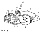
- FIG. 2 is a left side view including the engine 40, the electric motor unit 80, and other components. As shown in FIG. 2, the air cleaner 46 is disposed above the electric motor unit 80.
- the air cleaner 46 is connected to the carburetor 48 via an air-cleaner side intake pipe 49B.
- the air cleaner 46 has an element (now shown) inside that purifies the air supplied to the carburetor 48 by removing the coarse particulate in the atmospheric air.
- the air-cleaner side intake pipe 49B is connected to the air cleaner 46, and has generally cylindrical shape.
- the carburetor 48 delivers fuel-air mixture, the fuel mixed with the air introduced from the outside, to the inside of a cylinder 42A (see FIG. 4) via an intake port inlet portion 41. Also, the carburetor 48 is connected to the intake port inlet portion 41 by means of a main intake pipe 49A. According to this embodiment, the carburetor 48 constitutes a fuel-air mixture delivery system.
- the main intake pipe 49A is connecting the carburetor 48 to the intake port inlet portion 41, and have generally cylindrical shape.
- the layout of the carburetor 48, the main intake pipe 49A, and the air-cleaner side intake pipe 49B is arranged to fit into the space formed above a crankshaft 43 of the engine 40.
- a radiator unit 45 to carry out cooling by means of the cooling water (LLC) of the engine 40, and the muffler 47 for reducing the exhaust noise from the engine 40 are connected to the engine 40.
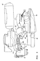
- FIG. 3 is a view on arrow F3 shown in FIG. 2.
- the air cleaner 46 is disposed at the left side of the rear wheel 90 in reference to the traveling direction of the motorcycle 10.
- the main intake pipe 49A and the air-cleaner side intake pipe 49B have arched shape in order to connect the air cleaner 46 disposed at the left side of the rear wheel 90 to the intake port inlet portion 41 disposed generally in the transverse center of the motorcycle 10.
- a protrusion 49Bp projecting into the internal space of the air cleaner 46 is provided at one end of the air-cleaner side intake pipe 49B.
- the muffler 47 is disposed at the right side of the rear wheel 90 in reference to the traveling direction of the motorcycle 10.
- the muffler 47 is connected to an exhaust port (not shown) of the engine 40 via an exhaust pipe 44.
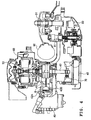
- FIG. 4 is a cross-sectional view along the line F4 - F4 in FIG. 1.
- the engine 40 rotates the generator unit 60 that generates electric power necessary for the electric motor unit 80 to rotate.
- the engine 40 is a single-cylinder four-stroke engine, in which a piston 42B provided within a cylinder 42A makes reciprocating movement to rotate a crankshaft 43 connected to it via a connecting rod 42C.
- the diameter of the bore B is designed at approximately 38mm according to this embodiment.
- a generator cooling fan 50 is mounted at one end of the crankshaft 43 that is located in the transversely outer position relative to the generator unit 60.
- a radiator cooling fan 70 to cool down the engine 40 (the radiator unit 45) is mounted at the other end of the crankshaft 43 located in the opposite side of the generator unit 60.
- the generator cooling fan 50 and the radiator cooling fan 70 rotate in conjunction with the rotation of the crankshaft 43.
- the generator cooling fan 50 and the radiator cooling fan 70 provide the cooling function for the generator unit 60 and for the electric motor unit 80, respectively.
- the electric motor unit 80 has a rotating shaft 81.
- the rotating shaft 81 rotates the rear wheel axle 91 via a transmission gear (not shown).
- the rear wheel 90 fixed to the rear wheel axle 91 is also made to rotate.
- the centerline length L1 measured from one end of the main intake pipe 49A at the intake port (the carburetor 48) side (position P1 in FIG. 5) to the intake port inlet portion 41 (position P2) is designed to be 3 to 15 times larger than the inside diameter ⁇ 1 of the main intake pipe 49A.
- a protrusion 49Bp projecting into the internal space of the air cleaner 46 is provided at one end of the air-cleaner side intake pipe 49B.
- the centerline length L2 of the air-cleaner side intake pipe 49B is designed to be 4 to 10 times larger than the inside diameter ⁇ 2 of the air-cleaner side intake pipe 49B.
- the centerline length L3 of the projection 49Bp is designed to be at least 2 times larger than the inside diameter ⁇ 2 of the air-cleaner side intake pipe 49B.
- the air cleaner 46 has an ambient air intake duct section 46a to take-in the outside air. A part of the ambient air intake duct section 46a is disposed in the inner space of the air cleaner 46.
- the capacity of the air cleaner 46 is designed to be 30 to 150 times larger than the displacement of the engine 40.
- the carburetor 48 has a venturi portion 48a (fuel-air mixture passing area) that fuel-air mixture (or air) flows through.
- the venturi portion 48a is a part with smaller bore diameter (the part of bore diameter ⁇ 3 as indicated in the Figure) relative to other part of the passage, in order to increase the flow velocity of fuel-air mixture.
- the fuel-air mixture is delivered into the engine 40 (not shown in FIG. 6) by way of the main intake pipe 49A having the inside diameter ⁇ 1 that is larger than the bore diameter ⁇ 3 at the venturi portion 48a.
- the cross-sectional area of the venturi portion 48a is designed to be 15 to 25 % relative to the cross-sectional area of the bore B (see FIG. 4) of the cylinder 42A.
- FIG. 7 shows the effects of the change in the centerline length L1 of the main intake pipe 49A on the torque characteristics of the engine 40.
- the dimensions of the main intake pipe 49A employed in the comparative example and the embodiment illustrated in FIG. 7 are as follows:
- the length L1 is designed to be about 11.7 times larger than the inside diameter ⁇ 1.
- maximum torque increases on the engine 40 equipped with the main intake pipe 49A according to the embodiment.
- the peak point of the torque is shifted into the lower engine speed range.
- centerline length L1 of the main intake pipe 49A is designed to fall under the range of 3 to 15 times larger than the inside diameter ⁇ 1 in the case of engine 40 according to the embodiment, such engine has been turned into a "low engine speed type" that generates high torque at the lower engine speed than the comparative example (conventional hybrid vehicle), without the need for substantial change in the engine components basic layout.
- the hybrid-driven vehicle such as the motorcycle 10
- FIG. 8 shows the effect of the change in the cross-sectional area of the venturi portion 48a in the carburetor 48, on the output power characteristics of the engine 40.
- the dimensions of the main intake pipe 49A employed in the comparative example and the embodiments illustrated in FIG. 8 are as follows:
- the cross-sectional area of the venturi portion 48a according to the embodiment 1 and the embodiment 2 is designed to fall under the range of 15 to 25 % of the cross-sectional area of the bore B, the maximum output power of the engine 40 according to the embodiment 1 and the embodiment 2 is higher than that of the comparative example.
- FIG. 9 describes the effect of the change in the centerline length L2 of the air-cleaner side intake pipe 49B, on the torque characteristics of the engine 40.
- the dimensions of the air-cleaner side intake pipe 49B employed in the comparative example and the embodiments 1 through 4 in FIG. 9 are as follows:
- maximum torque increases on the engine 40 equipped with the air-cleaner side intake pipe 49B according to the embodiments 1 through 4.
- the peak point of the torque is shifted into lower engine speed range.
- centerline length L2 of the air-cleaner side intake pipe 49B is designed to fall under the range of 4 to 10 times larger than the inside diameter ⁇ 2 in the case of engine 40 according to the embodiments 1 though 4, such engine has been turned into a "low engine speed type" that generates high torque at the lower engine speed than the comparative example.
- the centerline length L2 of the air-cleaner side intake pipe 49B is designed not to fall under the range of 4 to 10 times larger than the inside diameter ⁇ 2, the engine 40 cannot be turned into a "low engine speed type" that generates high torque at the lower engine speed than the comparative example.
- one end of the air-cleaner side intake pipe 49B is projected into the internal space of the air cleaner 46 (in the embodiments 3 and 4). Setting adjustments, such as changing the engine speed at which the maximum torque is generated, can be made easily by varying the relevant projected length.
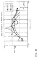
- FIG. 10 shows the effect of the change in the capacity of the air cleaner 46 on the torque characteristics of the engine 40.
- the capacity of the air cleaner 46 employed in the comparative example and the embodiments 1 through 4 in FIG. 10 are as follows:
- the engine 40 according to the embodiments 1 through 4 attains higher maximum torque than that of the comparative example, as the capacity of the air cleaner 46 is designed to fall under the range of 30, 38 to 150 times larger than the displacement of the engine 40. In addition, the peak point of the torque is shifted into the lower engine speed range.
- the air cleaner 46 as described above may be altered as follows:
- FIG. 11 is a schematic perspective view of an air cleaner 46V according to the alternative embodiment of this invention.
- the air cleaner 46V may be coupled to the engine 40 in place of the air cleaner 46 described above.
- the air cleaner 46V has the first air cleaner 461 and the second air cleaner 462.
- the first air cleaner 461 and the second air cleaner 462 are communicated by a connecting part 463.
- the air cleaner 46V is equipped to the motorcycle 10 in the manner that the rear wheel 90 is disposed in the space in between the first air cleaner 461 and the second air cleaner 462 which are communicated by the connecting part 463.
- the first air cleaner 461 is disposed at the right side of the rear wheel 90, and the second air cleaner 462 is disposed at the left side of the rear wheel 90, both in reference to the traveling direction of the motorcycle 10.
- air cleaner 46V By employing the air cleaner 46V, air cleaner having larger capacity (up to 150 times larger) relative to the displacement of the engine 40 can be equipped easily to the motorcycle 10, without making an impact on the external appearance of the motorcycle 10 and the drivability of the motorcycle 10.
- the ambient air intake duct section 46a is provided as shown in FIG. 5.
- an ambient air intake duct section 46b (shown with long and short dashed line in FIG. 5) may be provided in place of the ambient air intake duct section 46a.
- the capacity of the air cleaner 46 is set to be 30 to 150 times larger than the displacement of the engine 40.
- the capacity of the air cleaner 46 is not necessarily in the range of 30 to 150 times larger than the displacement of the engine 40.
- a part of the ambient air intake duct section 46a is disposed in the inner space of the air cleaner 46.
- a part of the ambient air intake duct section 46a is not necessarily disposed in the inner space of the air cleaner 46.
- the air-cleaner side intake pipe 49B falls under the given range (4 to 10 times larger than the inside diameter ⁇ 2), and that one end of the air-cleaner side intake pipe 49B projects into the inner space of the air cleaner 46.
- the air-cleaner side intake pipe 49B does not always have to be arranged this way.
- the cross-sectional area of the venture portion 48a is designed to be 15 to 25 % of the cross-sectional area of the bore B.
- the cross-sectional area of the venture portion 48a is not necessarily designed to be 15 to 25 % of the cross-sectional area of the bore B.
- the carburetor 48 is formed to use the carburetor 48 as the fuel-air mixture delivery system.
- a fuel injection system may be used in place of the carburetor 48.
- the bore diameter of the position where fuel-air mixture (or air) passes through in the throttle body can be considered as equal to the bore diameter ⁇ 3 of the venture portion 48a.
- the series-hybrid-driven system is employed in the motorcycle 10 according to the embodiment of this invention described above.
- the invention may be applied to the parallel-hybrid-driven vehicle in which the rear wheel 90 is driven by the engine and the motor (electric motor unit).
- teaching of this invention may be applied to any hybrid vehicle in which the rear wheel 90 is driven at least either by the engine or by the motor.
- a hybrid vehicle having: an engine (an engine 40), a motor (an electric motor unit 80); a generator (a generator unit 60) rotated by the engine; and a wheel driven at least either by the engine or by the motor (a rear wheel 90), wherein the engine has a cylinder (a cylinder 42A), an intake port communicating with the cylinder (an intake port inlet portion 41), a fuel-air mixture delivery system (a carburetor 48) for delivering fuel-air mixture, that is the fuel mixed with the air introduced from the outside, to the inside of a cylinder via the intake port, and a main intake pipe (a main intake pipe 49A) having generally cylindrical shape and connecting the fuel-air mixture delivery system to the intake port; and the centerline length (a length L1) measured from the intake port end of the main intake pipe (position P1) to the intake port inlet (position P2) is 3 (three) to 15 (fifteen) times larger than the inside diameter of the main intake pipe (
- the centerline length of the main intake pipe is designed to be 3 to 15 times larger than the inside diameter, higher torque is generated at lower engine speed than the conventional hybrid vehicle, without the need for substantial change in the engine components basic layout found in the conventional hybrid vehicle.
- the hybrid vehicle Especially for the hybrid vehicle, it is necessary to restrict the upper limit of the speed for the internal combustion engine to approximately 6,000 engine speed, in order to realize low noise and low vibration that is comparable to those of electric vehicles.
- the peak point of the torque is shifted into lower engine speed range in comparison with the traditional hybrid vehicle, and thus, necessary and sufficient torque is generated while restricting the engine speed upper limit of the internal combustion engine at 6,000 engine speed or lower.
- a hybrid vehicle that allows reduction of sound level, vibration, and fuel consumption involving the vehicle operation can be provided.
- the fuel-air mixture delivery system has a fuel-air mixture passing portion (a venture portion 48a) through which the fuel-air mixture or the air flows, and the cross-sectional area of the fuel-air mixture passing portion, cut along the direction generally orthogonal to the passing flow of the fuel-air mixture or air, is designed to be 15 to 25 % relative to the cross-sectional area of a bore of the cylinder.
- the hybrid vehicle further has an air cleaner (an air cleaner 46), and an air-cleaner side intake pipe taking generally cylindrical shape and connected to the air cleaner (an air-cleaner side intake pipe 49B), wherein the centerline length of the air-cleaner side intake pipe (length L2) is 4 to 10 times larger than the inside diameter of the air-cleaner side intake pipe (inside diameter ⁇ 2).
- one end of the air-cleaner side intake pipe has a protrusion projecting into the inside space of the air cleaner; and the centerline length of the protrusion (length L3) is twice or more larger than the inside diameter of the air-cleaner side intake pipe.
- the air cleaner has an ambient air intake duct section (an ambient air intake duct section 46a) and a part of the ambient air intake duct section is disposed in the inner space of the air cleaner.
- the capacity of the air cleaner is 30 to 150 times larger than the displacement of the engine.
- a hybrid vehicle that allows reduction of sound level, vibration, and fuel consumption involving the vehicle operation can be provided.
- an engine 40 according to this invention has a carburetor 48 for delivering fuel-air mixture, i.e.
Landscapes
- Engineering & Computer Science (AREA)
- Mechanical Engineering (AREA)
- Chemical & Material Sciences (AREA)
- Combustion & Propulsion (AREA)
- Transportation (AREA)
- General Engineering & Computer Science (AREA)
- Power Engineering (AREA)
- Hybrid Electric Vehicles (AREA)
- Cooling, Air Intake And Gas Exhaust, And Fuel Tank Arrangements In Propulsion Units (AREA)
Abstract
Description
- The present invention relates to an engine, in particular for a hybrid vehicle and to a hybrid vehicle having an engine, a motor, a generator rotated by the engine, and a wheel driven at least either by the engine or by the motor.
- To date, a hybrid-driven type (so-called parallel-hybrid-driven type) vehicle (straddle type vehicle) has been proposed, which uses an engine (internal combustion engine) and an electric motor (motor) as the power source for driving wheels.
- In addition, another hybrid-driven type (so-called series-hybrid-driven type) vehicle (straddle type vehicle) has been proposed, which uses an electric motor as a power source for driving a wheel, a generator (electric motor) for charging the battery connected to the electric motor, and an engine for making the generator rotate.
- Such hybrid-driven type vehicle (hereinafter referred to as "hybrid vehicle") has typically employed high speed type engine that mainly uses the engine horsepower for obtaining necessary and sufficient acceleration performance with limited output power, as is the case for a small vehicle relying on an engine as its power source (the engine with the displacement of 50cc, for instance) (
JP-A-2000-13913 Pages 3, FIG. 1)). - However, the engine (internal combustion engine) used in the conventional hybrid vehicle described above had problems as stated below. Namely, such problem includes high noise level and vibration emitted during the operation of hybrid vehicle, which is attributable to the higher speed of the engine. In other words, difficulty lies in the conventional hybrid vehicle to attain low noise level and low vibration, the advantage of the electric bestriding (saddle-riding) vehicle.
- Further, it involved a problem of increased fuel consumption because of the higher speed of the engine. Also, it involved a problem of increased frictional loss because the drive train of the hybrid vehicle rotates in high speed corresponding to the higher speed of the engine.
- Thus, the present invention has been made in light of the circumstances described above. It is therefore an object of the present invention to provide an engine and a hybrid vehicle that can reduce noise level and vibration during the vehicle operation, and also can reduce the fuel consumption.
- This objective is solved in an inventive manner by an engine, in particular for a hybrid vehicle, comprising a fuel-air mixture delivery system delivering fuel-air mixture to a cylinder of the engine and a main intake pipe connecting the fuel-air mixture delivery system to an intake port inlet portion of the cylinder, wherein a length along a centerline of the main intake pipe measured from an intake port end of the main intake pipe to the intake port inlet portion is in the range of 3 to 15 times larger than an inside diameter of the main intake pipe.
- Preferably, the main intake pipe has a generally cylindrical shape.
- According to a further embodiment, the fuel-air mixture delivery system has a fuel-air mixture passing portion through which the fuel-air mixture or the air flows, and wherein a cross-sectional area of said fuel-air mixture passing portion, cut along a direction generally orthogonal to the passing flow of the fuel-air mixture or air, is designed to be 15 % to 25 % of a cross-sectional area of a cylinder bore.
- Further, preferably the engine further comprises an air cleaner and an air-cleaner side intake pipe, said air-cleaner side intake pipe having a generally cylindrical shape and being connected to the air cleaner, wherein a centerline length of the air-cleaner side intake pipe is 4 to 10 times larger than an inside diameter of the air-cleaner side intake pipe.
- Therein, one end of the air-cleaner side intake pipe may have a protrusion projecting into an inside space of the air cleaner; wherein a centerline length of said protrusion may be twice or more larger than the inside diameter of the air-cleaner side intake pipe. Further, the air cleaner may have an ambient air intake duct section, wherein a part of said ambient air intake duct section may be disposed in the inner space of the air cleaner. Also, a capacity of the air cleaner may be 30 to 150 times larger than a displacement of the engine.
- The above objective is further solved in an inventive manner by a hybrid vehicle, having an engine, a motor, a generator rotated by the engine, and a wheel driven at least either by the engine or by the motor, wherein the engine comprises a cylinder, an intake port communicating with the cylinder, a fuel-air mixture delivery system for delivering fuel-air mixture, that is the fuel mixed with the air introduced from the outside, to the inside of a cylinder via the intake port, and a main intake pipe having generally cylindrical shape and connecting the fuel-air mixture delivery system to the intake port; and a centerline length (L1 ) measured from the intake port end of the main intake pipe to the intake port inlet is 3 to 15 times larger than the inside diameter of the main intake pipe.
- Preferably, the fuel-air mixture delivery system has a fuel-air mixture passing portion through which the fuel-air mixture or the air flows, and the cross-sectional area of the fuel-air mixture passing portion, cut along the direction generally orthogonal to the passing flow of the fuel-air mixture or air, is designed to be 15 % to 25 % relative to the cross-sectional area of a cylinder bore.
- Further, preferably the hybrid vehicle further comprises an air cleaner and an air-cleaner side intake pipe taking generally cylindrical shape and connected to the air cleaner, wherein a centerline length of the air-cleaner side intake pipe is 4 to 10 times larger than the inside diameter of the air-cleaner side intake pipe.
- According to a further preferred embodiment, one end of the air-cleaner side intake pipe has a protrusion projecting into the inside space of the air cleaner; and a centerline length of the protrusion is twice or more larger than the inside diameter of the air-cleaner side intake pipe. Therein, the air cleaner may have an ambient air intake duct section, and a part of the ambient air intake duct section may be disposed in the inner space of the air cleaner.
- Further, a capacity of the air cleaner may be 30 to 150 times larger than a displacement of the engine.
- In the following, the present invention is explained in greater detail with respect to several embodiments thereof in conjunction with the accompanying drawings, wherein:
- FIG. 1
- is a left side view of a motorcycle according to the embodiment,
- FIG. 2
- is a left side view of an internal combustion engine, an electric motor, and the like according to the embodiment,
- FIG. 3
- is a view on arrow F3 shown in FIG. 2,
- FIG. 4
- is a cross-sectional view along the line F4 - F4 in FIG. 1,
- FIG. 5
- is a top plan view of an air cleaner, a main intake pipe, and an air-cleaner side intake pipe according to the embodiment,
- FIG. 6
- is a schematic perspective view of a fuel-air mixture delivery system (carburetor) according to the embodiment,
- FIG. 7
- is an illustration to show the relation between the main intake pipe length and the torque characteristics of an engine according to the embodiment,
- FIG. 8
- is an illustration to show the relation between the main intake pipe length and the torque characteristics of an engine according to the embodiment,
- FIG. 9
- is an illustration to show the relation between the length of air-cleaner side intake pipe and the torque characteristics of an engine according to the embodiment,
- FIG. 10
- is an illustration to show the relation between the capacity of the air cleaner and the torque characteristics of an engine according to the embodiment, and
- FIG. 11
- is a schematic perspective view of the air cleaner of an engine according to the embodiment.
-
- 10:
- is a motorcycle,
- 20:
- is a front wheel,
- 40:
- is an engine,
- 41:
- is an intake port inlet portion,
- 42A:
- is a cylinder,
- 42B:
- is a piston,
- 42C:
- is a connecting rod,
- 43:
- is a crankshaft,
- 44:
- is an exhaust pipe,
- 45:
- is a radiator unit,
- 46, 46V:
- is an air cleaner,
- 46a, 46b:
- is an ambient air intake duct section,
- 47:
- is a muffler,
- 48:
- is a carburetor,
- 48a:
- is a venturi portion,
- 49A:
- is a main intake pipe,
- 49b:
- is an air-cleaner side intake pipe,
- 49Bp:
- is a protrusion,
- 50:
- is a generator cooling fan,
- 60:
- is a generator unit,
- 61:
- is a battery,
- 70:
- is a radiator cooling fan,
- 80:
- is an electric motor unit,
- 81:
- is a rotating shaft,
- 90:
- is a rear wheel,
- 91:
- is a rear wheel axle,
- 461:
- is a first air cleaner part,
- 462:
- is a second air cleaner part, and
- 463:
- is a connecting part.
- Next, an embodiment of a vehicle (a motorcycle) will be described with reference to the drawings. For reference, identical or similar reference numerals or symbols are used to denote identical or similar parts in the description of the following drawings. It should be noted, however, that the drawings show typical configuration, and that they are different from the actual object in regard to the relative proportion between each dimension, etc.
- Thus, the specific dimensions or the like shall be established taking account of the following description. Needless to say, some differences exist in relative dimensions and proportions between the drawings.
- First, general structure of a
motorcycle 10, which is a hybrid vehicle according to this embodiment, will be described with reference to FIG. 1. - As shown in FIG. 1, the
motorcycle 10 is a straddle type two-wheel vehicle having afront wheel 20 and arear wheel 90. Themotorcycle 10 is so called a hybrid-driven type (more specifically, series-hybrid-driven type) vehicle, in which therear wheel 90 is rotated by an electric motor unit 80 (an electric motor) disposing forward side of arear wheel axle 91. - A generator unit 60 (see FIG. 4) is connected to a
battery 61 which accumulates electric power to be supplied to theelectric motor unit 80 and the like. The generator unit 60 (generator) is rotated by anengine 40, and the generated electric power is accumulated in thebattery 61. - In addition, an
air cleaner 46 for purifying the air supplied to theengine 40, or to acarburetor 48 to be more precise, as well as amuffler 47 for reducing the exhaust noise from theengine 40 are connected to theengine 40. - Next, the structure around the
engine 40 will be described with reference to FIG. 2 through FIG. 4. FIG. 2 is a left side view including theengine 40, theelectric motor unit 80, and other components. As shown in FIG. 2, theair cleaner 46 is disposed above theelectric motor unit 80. - The
air cleaner 46 is connected to thecarburetor 48 via an air-cleanerside intake pipe 49B. Theair cleaner 46 has an element (now shown) inside that purifies the air supplied to thecarburetor 48 by removing the coarse particulate in the atmospheric air. - The air-cleaner
side intake pipe 49B is connected to theair cleaner 46, and has generally cylindrical shape. - The
carburetor 48 delivers fuel-air mixture, the fuel mixed with the air introduced from the outside, to the inside of acylinder 42A (see FIG. 4) via an intakeport inlet portion 41. Also, thecarburetor 48 is connected to the intakeport inlet portion 41 by means of amain intake pipe 49A. According to this embodiment, thecarburetor 48 constitutes a fuel-air mixture delivery system. - The
main intake pipe 49A is connecting thecarburetor 48 to the intakeport inlet portion 41, and have generally cylindrical shape. - According to this embodiment, the layout of the
carburetor 48, themain intake pipe 49A, and the air-cleanerside intake pipe 49B is arranged to fit into the space formed above acrankshaft 43 of theengine 40. - Also, a
radiator unit 45 to carry out cooling by means of the cooling water (LLC) of theengine 40, and themuffler 47 for reducing the exhaust noise from theengine 40 are connected to theengine 40. - FIG. 3 is a view on arrow F3 shown in FIG. 2. As shown in FIG. 3, the
air cleaner 46 is disposed at the left side of therear wheel 90 in reference to the traveling direction of themotorcycle 10. Further, themain intake pipe 49A and the air-cleanerside intake pipe 49B have arched shape in order to connect theair cleaner 46 disposed at the left side of therear wheel 90 to the intakeport inlet portion 41 disposed generally in the transverse center of themotorcycle 10. - In addition, a protrusion 49Bp projecting into the internal space of the
air cleaner 46 is provided at one end of the air-cleanerside intake pipe 49B. - The
muffler 47 is disposed at the right side of therear wheel 90 in reference to the traveling direction of themotorcycle 10. Themuffler 47 is connected to an exhaust port (not shown) of theengine 40 via anexhaust pipe 44. - FIG. 4 is a cross-sectional view along the line F4 - F4 in FIG. 1. The
engine 40 rotates thegenerator unit 60 that generates electric power necessary for theelectric motor unit 80 to rotate. - The
engine 40 is a single-cylinder four-stroke engine, in which apiston 42B provided within acylinder 42A makes reciprocating movement to rotate acrankshaft 43 connected to it via a connectingrod 42C. The diameter of the bore B is designed at approximately 38mm according to this embodiment. - A
generator cooling fan 50 is mounted at one end of thecrankshaft 43 that is located in the transversely outer position relative to thegenerator unit 60. At the same time, aradiator cooling fan 70 to cool down the engine 40 (the radiator unit 45) is mounted at the other end of thecrankshaft 43 located in the opposite side of thegenerator unit 60. - The
generator cooling fan 50 and theradiator cooling fan 70 rotate in conjunction with the rotation of thecrankshaft 43. Thegenerator cooling fan 50 and theradiator cooling fan 70 provide the cooling function for thegenerator unit 60 and for theelectric motor unit 80, respectively. - The
electric motor unit 80 has arotating shaft 81. The rotatingshaft 81 rotates therear wheel axle 91 via a transmission gear (not shown). As therear wheel axle 91 is made to rotate by theelectric motor unit 80, therear wheel 90 fixed to therear wheel axle 91 is also made to rotate. - Next, the structure of the
air cleaner 46, themain intake pipe 49A, and the air-cleanerside intake pipe 49B will be described more specifically, referring to FIG. 5. - As shown in FIG. 5, according to this embodiment, the centerline length L1 measured from one end of the
main intake pipe 49A at the intake port (the carburetor 48) side (position P1 in FIG. 5) to the intake port inlet portion 41 (position P2) is designed to be 3 to 15 times larger than the inside diameter ϕ1 of themain intake pipe 49A. - In addition, as referred to above, a protrusion 49Bp projecting into the internal space of the
air cleaner 46 is provided at one end of the air-cleanerside intake pipe 49B. According to this embodiment, the centerline length L2 of the air-cleanerside intake pipe 49B is designed to be 4 to 10 times larger than the inside diameter ϕ2 of the air-cleanerside intake pipe 49B. - Further according to this embodiment, the centerline length L3 of the projection 49Bp is designed to be at least 2 times larger than the inside diameter ϕ2 of the air-cleaner
side intake pipe 49B. - The
air cleaner 46 has an ambient airintake duct section 46a to take-in the outside air. A part of the ambient airintake duct section 46a is disposed in the inner space of theair cleaner 46. In addition, according to this embodiment, the capacity of theair cleaner 46 is designed to be 30 to 150 times larger than the displacement of theengine 40. - Next, the structure of the
carburetor 48 that constitutes the fuel-air mixture delivery system according to this embodiment will be described more specifically, with reference to FIG. 6. - As shown in FIG. 6, the
carburetor 48 has aventuri portion 48a (fuel-air mixture passing area) that fuel-air mixture (or air) flows through. Theventuri portion 48a is a part with smaller bore diameter (the part of bore diameter ϕ3 as indicated in the Figure) relative to other part of the passage, in order to increase the flow velocity of fuel-air mixture. After passing through theventuri portion 48a, the fuel-air mixture is delivered into the engine 40 (not shown in FIG. 6) by way of themain intake pipe 49A having the inside diameter ϕ1 that is larger than the bore diameter ϕ3 at theventuri portion 48a. - According to this embodiment, the cross-sectional area of the
venturi portion 48a, or more specifically, the cross-sectional area of theventuri portion 48a cut along the direction generally orthogonal to the passing flow of the fuel-air mixture (or air), is designed to be 15 to 25 % relative to the cross-sectional area of the bore B (see FIG. 4) of thecylinder 42A. - Next, function and effectiveness of the
motorcycle 10 according to the aforementioned embodiment will be described referring to the FIG. 7 through FIG. 10. - FIG. 7 shows the effects of the change in the centerline length L1 of the
main intake pipe 49A on the torque characteristics of theengine 40. The dimensions of themain intake pipe 49A employed in the comparative example and the embodiment illustrated in FIG. 7 are as follows: - Comparative example: Length L1 = 50mm, Inside diameter ϕ1 = 19.5mm
- Embodiment: Length L1 = 230mm (+180mm), Inside diameter ϕ1 = 19.5mm
- This means that, in the
main intake pipe 49A according to the embodiment, the length L1 is designed to be about 11.7 times larger than the inside diameter ϕ1. - As shown in FIG. 7, maximum torque increases on the
engine 40 equipped with themain intake pipe 49A according to the embodiment. In addition, the peak point of the torque is shifted into the lower engine speed range. - In other words, as the centerline length L1 of the
main intake pipe 49A is designed to fall under the range of 3 to 15 times larger than the inside diameter ϕ1 in the case ofengine 40 according to the embodiment, such engine has been turned into a "low engine speed type" that generates high torque at the lower engine speed than the comparative example (conventional hybrid vehicle), without the need for substantial change in the engine components basic layout. - Especially for the hybrid-driven vehicle, such as the
motorcycle 10, it is necessary to restrict the upper limit of the speed for theengine 40 to approximately 6,000 engine speed, in order to realize low noise and low vibration that is comparable to those of electric vehicles. Since the peak point of the torque is shifted into the lower engine speed range in theengine 40 according to the embodiment, necessary and sufficient torque to rotate thegenerator unit 60 is attained while restricting the engine speed upper limit of theengine 40 at 6,000 engine speed or lower. - On the other hand, if the centerline length L1 of the
main intake pipe 49A is designed not to fall under the range of 3 to 15 times larger than the inside diameter φ1, it is impracticable to attain necessary and sufficient torque to rotate thegenerator unit 60, while restricting the speed upper limit of theengine 40 at 6,000 engine speed or lower. - FIG. 8 shows the effect of the change in the cross-sectional area of the
venturi portion 48a in thecarburetor 48, on the output power characteristics of theengine 40. The dimensions of themain intake pipe 49A employed in the comparative example and the embodiments illustrated in FIG. 8 are as follows: - Comparative example Bore diameter ϕ3 = 18.5mm (area ratio 24%)
-
Embodiment 1 Bore diameter ϕ3 = 15.0mm (area ratio 16%) -
Embodiment 2 Bore diameter ϕ3 = 18.0mm (area ratio 22%) - Note that "area ratio" means the percentage of the cross-sectional area at the
venture portion 48a relative to the cross-sectional area of the bore B in the engine 40 (diameter = approximately 38mm). - As shown in FIG. 8, since the cross-sectional area of the
venturi portion 48a according to theembodiment 1 and theembodiment 2 is designed to fall under the range of 15 to 25 % of the cross-sectional area of the bore B, the maximum output power of theengine 40 according to theembodiment 1 and theembodiment 2 is higher than that of the comparative example. - On the other hand, if the cross-sectional area of the
venturi portion 48a does not fall under the range of 15 to 25 % of the cross-sectional area of the bore B, the maximum output power of theengine 40 cannot be improved as shown in FIG. 8. - FIG. 9 describes the effect of the change in the centerline length L2 of the air-cleaner
side intake pipe 49B, on the torque characteristics of theengine 40. The dimensions of the air-cleanerside intake pipe 49B employed in the comparative example and theembodiments 1 through 4 in FIG. 9 are as follows: - Comparative example:
- Length L2 = 139mm, Inside diameter ϕ2 = 34mm (4.1)
- Protrusion projecting into the internal space of the air cleaner 46: None
- Embodiment 1:
- Length L2 = 200mm, Inside diameter ϕ2 = 34mm (5.9)
- Protrusion projecting into the internal space of the air cleaner 46: None
- Embodiment 2:
- Length L2 = 60mm, Inside diameter ϕ2 = 34mm
- Length L2 = 140mm, Inside diameter ϕ2 = 28mm (equivalent to 6.7)
- Protrusion projecting into the internal space of the air cleaner 46: None
- Embodiment 3:
- Length L2 = 60mm, Inside diameter ϕ2 = 34mm
- Length L2 = 140mm, Inside diameter ϕ2 = 26mm (equivalent to 6.7)
- Protrusion projecting into the internal space of the air cleaner 46: 100mm
- Embodiment 4:
- Length L2 = 60mm, Inside diameter ϕ2 = 34mm
- Length L2 = 140mm, Inside diameter ϕ2 = 24mm (equivalent to 6.7)
- Protrusion projecting into the internal space of the air cleaner 46: 160mm
- Note that the numerals in the parenthesis represent the proportion of the length L2 against the inside diameter ϕ2 of the air-cleaner
side intake pipe 49B. - As shown in FIG. 9, maximum torque increases on the
engine 40 equipped with the air-cleanerside intake pipe 49B according to theembodiments 1 through 4. In addition, the peak point of the torque is shifted into lower engine speed range. - In other words, as the centerline length L2 of the air-cleaner
side intake pipe 49B is designed to fall under the range of 4 to 10 times larger than theinside diameter φ 2 in the case ofengine 40 according to theembodiments 1 though 4, such engine has been turned into a "low engine speed type" that generates high torque at the lower engine speed than the comparative example. - On the other hand, the centerline length L2 of the air-cleaner
side intake pipe 49B is designed not to fall under the range of 4 to 10 times larger than theinside diameter φ 2, theengine 40 cannot be turned into a "low engine speed type" that generates high torque at the lower engine speed than the comparative example. - Further, one end of the air-cleaner
side intake pipe 49B is projected into the internal space of the air cleaner 46 (in theembodiments 3 and 4). Setting adjustments, such as changing the engine speed at which the maximum torque is generated, can be made easily by varying the relevant projected length. - FIG. 10 shows the effect of the change in the capacity of the
air cleaner 46 on the torque characteristics of theengine 40. The capacity of theair cleaner 46 employed in the comparative example and theembodiments 1 through 4 in FIG. 10 are as follows: - Comparative example: 1,500cc (30 times)
- Embodiment 1: 7,500cc (150 times)
- Embodiment 2: 1,900cc (38 times)
- Embodiment 3: 3,500cc (70 times)
- Embodiment 4: 6,700cc (134 times)
- Note that the numerals in the parenthesis represent the proportion of the capacity of
air cleaner 46 against the displacement (50cc) of theengine 40. - As shown in FIG. 10, the
engine 40 according to theembodiments 1 through 4 attains higher maximum torque than that of the comparative example, as the capacity of theair cleaner 46 is designed to fall under the range of 30, 38 to 150 times larger than the displacement of theengine 40. In addition, the peak point of the torque is shifted into the lower engine speed range. - On the other hand, if the capacity of the
air cleaner 46 does not fall under the range of 30, 38 to 150 times larger than the displacement of theengine 40, the torque characteristics of theengine 40 cannot be altered as shown in FIG. 10. - In the description so far, the contents of this invention has been disclosed through one of the embodiments according to the invention, but the statement and the drawings constituting a part of the disclosure should not be construed to limit the invention. One of ordinary skill in the art will be able to identify various alternative embodiments based on the disclosure above.
- For instance, the
air cleaner 46 as described above may be altered as follows: - FIG. 11 is a schematic perspective view of an
air cleaner 46V according to the alternative embodiment of this invention. Theair cleaner 46V may be coupled to theengine 40 in place of theair cleaner 46 described above. - The
air cleaner 46V has thefirst air cleaner 461 and thesecond air cleaner 462. Thefirst air cleaner 461 and thesecond air cleaner 462 are communicated by a connectingpart 463. - More specifically, the
air cleaner 46V is equipped to themotorcycle 10 in the manner that therear wheel 90 is disposed in the space in between thefirst air cleaner 461 and thesecond air cleaner 462 which are communicated by the connectingpart 463. - In other words, the
first air cleaner 461 is disposed at the right side of therear wheel 90, and thesecond air cleaner 462 is disposed at the left side of therear wheel 90, both in reference to the traveling direction of themotorcycle 10. - By employing the
air cleaner 46V, air cleaner having larger capacity (up to 150 times larger) relative to the displacement of theengine 40 can be equipped easily to themotorcycle 10, without making an impact on the external appearance of themotorcycle 10 and the drivability of themotorcycle 10. - Further, according to the embodiment of this invention described above, the ambient air
intake duct section 46a is provided as shown in FIG. 5. However, an ambient airintake duct section 46b (shown with long and short dashed line in FIG. 5) may be provided in place of the ambient airintake duct section 46a. - In addition, according to the embodiment of this invention described above, the capacity of the
air cleaner 46 is set to be 30 to 150 times larger than the displacement of theengine 40. However, the capacity of theair cleaner 46 is not necessarily in the range of 30 to 150 times larger than the displacement of theengine 40. - In addition, according to the embodiment of this invention described above, a part of the ambient air
intake duct section 46a is disposed in the inner space of theair cleaner 46. However, a part of the ambient airintake duct section 46a is not necessarily disposed in the inner space of theair cleaner 46. - Further in addition, according to the embodiment of this invention described above, it is formed in such a way that the centerline length L2 of the air-cleaner
side intake pipe 49B falls under the given range (4 to 10 times larger than the inside diameter ϕ2), and that one end of the air-cleanerside intake pipe 49B projects into the inner space of theair cleaner 46. However, the air-cleanerside intake pipe 49B does not always have to be arranged this way. - According to the embodiment of this invention described above, the cross-sectional area of the
venture portion 48a is designed to be 15 to 25 % of the cross-sectional area of the bore B. However, the cross-sectional area of theventure portion 48a is not necessarily designed to be 15 to 25 % of the cross-sectional area of the bore B. - Further, according to the embodiment of this invention described above, it is formed to use the
carburetor 48 as the fuel-air mixture delivery system. However, a fuel injection system may be used in place of thecarburetor 48. In such case, the bore diameter of the position where fuel-air mixture (or air) passes through in the throttle body can be considered as equal to the bore diameter ϕ3 of theventure portion 48a. - In addition, the series-hybrid-driven system is employed in the
motorcycle 10 according to the embodiment of this invention described above. However, the invention may be applied to the parallel-hybrid-driven vehicle in which therear wheel 90 is driven by the engine and the motor (electric motor unit). - In other words, the teaching of this invention may be applied to any hybrid vehicle in which the
rear wheel 90 is driven at least either by the engine or by the motor. - The description above discloses (amongst others) a first embodiment of a hybrid vehicle (a motorcycle 10), having: an engine (an engine 40), a motor (an electric motor unit 80); a generator (a generator unit 60) rotated by the engine; and a wheel driven at least either by the engine or by the motor (a rear wheel 90), wherein the engine has a cylinder (a
cylinder 42A), an intake port communicating with the cylinder (an intake port inlet portion 41), a fuel-air mixture delivery system (a carburetor 48) for delivering fuel-air mixture, that is the fuel mixed with the air introduced from the outside, to the inside of a cylinder via the intake port, and a main intake pipe (amain intake pipe 49A) having generally cylindrical shape and connecting the fuel-air mixture delivery system to the intake port; and the centerline length (a length L1) measured from the intake port end of the main intake pipe (position P1) to the intake port inlet (position P2) is 3 (three) to 15 (fifteen) times larger than the inside diameter of the main intake pipe (inside diameter ϕ1). - According to such characteristic, since the centerline length of the main intake pipe is designed to be 3 to 15 times larger than the inside diameter, higher torque is generated at lower engine speed than the conventional hybrid vehicle, without the need for substantial change in the engine components basic layout found in the conventional hybrid vehicle.
- Especially for the hybrid vehicle, it is necessary to restrict the upper limit of the speed for the internal combustion engine to approximately 6,000 engine speed, in order to realize low noise and low vibration that is comparable to those of electric vehicles. In the hybrid vehicle provided with the characteristics described above, the peak point of the torque is shifted into lower engine speed range in comparison with the traditional hybrid vehicle, and thus, necessary and sufficient torque is generated while restricting the engine speed upper limit of the internal combustion engine at 6,000 engine speed or lower.
- In other words, according to the characteristic, a hybrid vehicle that allows reduction of sound level, vibration, and fuel consumption involving the vehicle operation can be provided.
- According to a second embodiment, the fuel-air mixture delivery system has a fuel-air mixture passing portion (a
venture portion 48a) through which the fuel-air mixture or the air flows, and the cross-sectional area of the fuel-air mixture passing portion, cut along the direction generally orthogonal to the passing flow of the fuel-air mixture or air, is designed to be 15 to 25 % relative to the cross-sectional area of a bore of the cylinder. - According to a third embodiment, the hybrid vehicle further has an air cleaner (an air cleaner 46), and an air-cleaner side intake pipe taking generally cylindrical shape and connected to the air cleaner (an air-cleaner
side intake pipe 49B), wherein the centerline length of the air-cleaner side intake pipe (length L2) is 4 to 10 times larger than the inside diameter of the air-cleaner side intake pipe (inside diameter ϕ2). - According to a fourth embodiment, one end of the air-cleaner side intake pipe has a protrusion projecting into the inside space of the air cleaner; and the centerline length of the protrusion (length L3) is twice or more larger than the inside diameter of the air-cleaner side intake pipe.
- According to a fifth embodiment, the air cleaner has an ambient air intake duct section (an ambient air
intake duct section 46a) and a part of the ambient air intake duct section is disposed in the inner space of the air cleaner. - According to a sixth embodiment, the capacity of the air cleaner is 30 to 150 times larger than the displacement of the engine.
- According to the characteristics of the present embodiments, a hybrid vehicle that allows reduction of sound level, vibration, and fuel consumption involving the vehicle operation can be provided.
- The description above discloses, as a particularly preferred embodiment, in order to provide a hybrid vehicle that allows reduction of sound level, vibration, and fuel consumption involving the vehicle operation, an
engine 40 according to this invention has acarburetor 48 for delivering fuel-air mixture, i.e. the fuel mixed with the air introduced from the outside, to the inside of a cylinder via an intakeport inlet portion 41, and amain intake pipe 49A having generally cylindrical shape, and connecting thecarburetor 48 and the intakeport inlet portion 41, wherein the centerline length measured from the intake port end of themain intake pipe 49A (position P1) to the intake port inlet (position P2) along the centerline of themain intake pipe 49A is in the range of 3 to 15 times larger than the inside diameter ϕ1 of themain intake pipe 49A.
Claims (13)
- Engine, in particular for a hybrid vehicle, comprising a fuel-air mixture delivery system (48) delivering fuel-air mixture to a cylinder of the engine and a main intake pipe (49A) connecting the fuel-air mixture delivery system (48) to an intake port inlet portion (41) of the cylinder, wherein a length (L1) along a centerline of the main intake pipe (49A) measured from an intake port end of the main intake pipe (49A) to the intake port inlet portion (41) is in the range of 3 to 15 times larger than an inside diameter (ϕ1) of the main intake pipe (49A).
- Engine according to claim 1, wherein the main intake pipe has a generally cylindrical shape.
- Engine according to claim 1 or 2, wherein the fuel-air mixture delivery system has a fuel-air mixture passing portion through which the fuel-air mixture or the air flows, and wherein a cross-sectional area of said fuel-air mixture passing portion, cut along a direction generally orthogonal to the passing flow of the fuel-air mixture or air, is designed to be 15 % to 25 % of a cross-sectional area of a cylinder bore.
- Engine according to one of the claims 1 to 3, further comprising an air cleaner and an air-cleaner side intake pipe, said air-cleaner side intake pipe having a generally cylindrical shape and being connected to the air cleaner, wherein a centerline length (L2) of the air-cleaner side intake pipe is 4 to 10 times larger than an inside diameter (ϕ2) of the air-cleaner side intake pipe.
- Engine according to claim 4, wherein one end of the air-cleaner side intake pipe has a protrusion (49Bp) projecting into an inside space of the air cleaner; and wherein a centerline length (L3) of said protrusion (49Bp) is twice or more larger than the inside diameter (ϕ2) of the air-cleaner side intake pipe.
- Engine according to claim 4 or 5, wherein the air cleaner has an ambient air intake duct section, and wherein a part of said ambient air intake duct section is disposed in the inner space of the air cleaner.
- Engine according to one of the claims 4 to 6, wherein a capacity of the air cleaner is 30 to 150 times larger than a displacement of the engine.
- Hybrid vehicle, having an engine, a motor, a generator rotated by the engine, and a wheel driven at least either by the engine or by the motor, wherein the engine comprises a cylinder, an intake port communicating with the cylinder, a fuel-air mixture delivery system for delivering fuel-air mixture, that is the fuel mixed with the air introduced from the outside, to the inside of a cylinder via the intake port, and a main intake pipe having generally cylindrical shape and connecting the fuel-air mixture delivery system to the intake port; and a centerline length (L1) measured from the intake port end of the main intake pipe to the intake port inlet is 3 to 15 times larger than the inside diameter of the main intake pipe.
- Hybrid vehicle according to claim 8, wherein the fuel-air mixture delivery system has a fuel-air mixture passing portion through which the fuel-air mixture or the air flows, and the cross-sectional area of the fuel-air mixture passing portion, cut along the direction generally orthogonal to the passing flow of the fuel-air mixture or air, is designed to be 15 % to 25 % relative to the cross-sectional area of a cylinder bore.
- Hybrid vehicle according to claim 8 or 9, further comprising an air cleaner and an air-cleaner side intake pipe taking generally cylindrical shape and connected to the air cleaner, wherein a centerline length (L2) of the air-cleaner side intake pipe is 4 to 10 times larger than the inside diameter of the air-cleaner side intake pipe.
- Hybrid vehicle according to claim 10, wherein one end of the air-cleaner side intake pipe has a protrusion projecting into the inside space of the air cleaner; and a centerline length (L3) of the protrusion is twice or more larger than the inside diameter of the air-cleaner side intake pipe.
- Hybrid vehicle according to claim 10 or 11, wherein the air cleaner has an ambient air intake duct section, and a part of the ambient air intake duct section is disposed in the inner space of the air cleaner.
- Hybrid vehicle according to one of the claims 10 to 12, wherein a capacity of the air cleaner is 30 to 150 times larger than a displacement of the engine.
Applications Claiming Priority (2)
| Application Number | Priority Date | Filing Date | Title |
|---|---|---|---|
| JP2005117269A JP2006290295A (en) | 2005-04-14 | 2005-04-14 | Saddle riding vehicle |
| JP2005120166A JP2006298062A (en) | 2005-04-18 | 2005-04-18 | Hybrid vehicle |
Publications (2)
| Publication Number | Publication Date |
|---|---|
| EP1712772A2 true EP1712772A2 (en) | 2006-10-18 |
| EP1712772A3 EP1712772A3 (en) | 2010-01-06 |
Family
ID=36627581
Family Applications (1)
| Application Number | Title | Priority Date | Filing Date |
|---|---|---|---|
| EP06007703A Withdrawn EP1712772A3 (en) | 2005-04-14 | 2006-04-12 | Hybrid vehicle and engine therefor |
Country Status (1)
| Country | Link |
|---|---|
| EP (1) | EP1712772A3 (en) |
Cited By (8)
| Publication number | Priority date | Publication date | Assignee | Title |
|---|---|---|---|---|
| WO2010082979A1 (en) * | 2009-01-16 | 2010-07-22 | Polaris Industries Inc. | Air intake system for controlling sound emission |
| CN101804848B (en) * | 2009-02-17 | 2013-05-29 | 本田技研工业株式会社 | Engines for two-wheeled motorcycles |
| CN106321304A (en) * | 2016-11-25 | 2017-01-11 | 安徽江淮汽车集团股份有限公司 | Spiral air-intake pipeline |
| US9809195B2 (en) | 2008-10-10 | 2017-11-07 | Polaris Industries Inc. | Snowmobile |
| US9845004B2 (en) | 2014-01-10 | 2017-12-19 | Polaris Industries Inc. | Snowmobile |
| US10493846B2 (en) | 2007-05-16 | 2019-12-03 | Polaris Industries Inc. | All terrain vehicle |
| US11286019B2 (en) | 2014-01-10 | 2022-03-29 | Polaris Industries Inc. | Snowmobile |
| US11505263B2 (en) | 2012-02-09 | 2022-11-22 | Polaris Industries Inc. | Snowmobile |
Citations (1)
| Publication number | Priority date | Publication date | Assignee | Title |
|---|---|---|---|---|
| JP2000013913A (en) | 1998-06-24 | 2000-01-14 | Honda Motor Co Ltd | Engine start and assist device |
Family Cites Families (1)
| Publication number | Priority date | Publication date | Assignee | Title |
|---|---|---|---|---|
| US7210444B2 (en) * | 2002-05-17 | 2007-05-01 | Brp-Rotax Gmbh & Co. Kg | Variable air intake pipe length |
-
2006
- 2006-04-12 EP EP06007703A patent/EP1712772A3/en not_active Withdrawn
Patent Citations (1)
| Publication number | Priority date | Publication date | Assignee | Title |
|---|---|---|---|---|
| JP2000013913A (en) | 1998-06-24 | 2000-01-14 | Honda Motor Co Ltd | Engine start and assist device |
Cited By (14)
| Publication number | Priority date | Publication date | Assignee | Title |
|---|---|---|---|---|
| US10493846B2 (en) | 2007-05-16 | 2019-12-03 | Polaris Industries Inc. | All terrain vehicle |
| US10974595B2 (en) | 2007-05-16 | 2021-04-13 | Polaris Industries Inc. | All terrain vehicle |
| US8127877B2 (en) | 2008-10-10 | 2012-03-06 | Polaris Industries Inc. | Air intake system for controlling sound emission |
| US9809195B2 (en) | 2008-10-10 | 2017-11-07 | Polaris Industries Inc. | Snowmobile |
| US11772601B2 (en) | 2008-10-10 | 2023-10-03 | Polaris Industries Inc. | Vehicle security system |
| RU2514807C2 (en) * | 2009-01-16 | 2014-05-10 | Поларис Индастриз Инк. | Air intake system for control over sound emission |
| WO2010082979A1 (en) * | 2009-01-16 | 2010-07-22 | Polaris Industries Inc. | Air intake system for controlling sound emission |
| CN101804848B (en) * | 2009-02-17 | 2013-05-29 | 本田技研工业株式会社 | Engines for two-wheeled motorcycles |
| US11505263B2 (en) | 2012-02-09 | 2022-11-22 | Polaris Industries Inc. | Snowmobile |
| US12286175B2 (en) | 2012-02-09 | 2025-04-29 | Polaris Industries Inc. | Snowmobile |
| US9845004B2 (en) | 2014-01-10 | 2017-12-19 | Polaris Industries Inc. | Snowmobile |
| US11286019B2 (en) | 2014-01-10 | 2022-03-29 | Polaris Industries Inc. | Snowmobile |
| US12296920B2 (en) | 2014-01-10 | 2025-05-13 | Polaris Industries Inc. | Snowmobile |
| CN106321304A (en) * | 2016-11-25 | 2017-01-11 | 安徽江淮汽车集团股份有限公司 | Spiral air-intake pipeline |
Also Published As
| Publication number | Publication date |
|---|---|
| EP1712772A3 (en) | 2010-01-06 |
Similar Documents
| Publication | Publication Date | Title |
|---|---|---|
| US6170597B1 (en) | Transmission for offroad vehicle | |
| AU741386B2 (en) | Motorcycle with hybrid drive system | |
| AU734641B2 (en) | Power unit arrangement structure for motorcycle | |
| CN1223471C (en) | Monotrack automobile | |
| WO2005069801A3 (en) | Fuel saving and pollution emission reduction system for internal combustion engines | |
| JPH10297294A (en) | Engine power transmission | |
| CN104339033A (en) | Hand-held work implement | |
| US20110073391A1 (en) | Hybrid vehicle | |
| US20230202286A1 (en) | Hybrid Power Train Structure In Off-Road Vehicle | |
| US5531291A (en) | Power plant for automobile | |
| US10563726B2 (en) | Drive unite for a motor vehicle | |
| JP2006298062A (en) | Hybrid vehicle | |
| JP3153112U (en) | Energy-saving exhaust muffler with spiral tail | |
| CA2409572A1 (en) | Transmission of internal combustion engine | |
| WO2010110025A1 (en) | Spiral tail for energy-saving exhaust muffler and spiral tail using method | |
| CN1129704C (en) | Air door valve rock arm installation of top-set valve type engine | |
| JP7584544B2 (en) | Engine-driven power supply unit | |
| US1221337A (en) | Internal-combustion engine. | |
| JPS6141683A (en) | Power transmission gear for bicycle with prime mover | |
| CN1337524A (en) | Air-suction device of engine | |
| JP4079112B2 (en) | Connection structure of drive device and internal combustion engine | |
| JP3007433B2 (en) | Vehicle powertrain structure | |
| JP2000064925A (en) | Fuel injection two-stroke engine | |
| US20080110428A1 (en) | Intensity magnetic field axle-free turbo fuel saver | |
| JPH01208559A (en) | Air cleaner device for engine of motorcycle |
Legal Events
| Date | Code | Title | Description |
|---|---|---|---|
| PUAI | Public reference made under article 153(3) epc to a published international application that has entered the european phase |
Free format text: ORIGINAL CODE: 0009012 |
|
| AK | Designated contracting states |
Kind code of ref document: A2 Designated state(s): AT BE BG CH CY CZ DE DK EE ES FI FR GB GR HU IE IS IT LI LT LU LV MC NL PL PT RO SE SI SK TR |
|
| AX | Request for extension of the european patent |
Extension state: AL BA HR MK YU |
|
| 17P | Request for examination filed |
Effective date: 20070419 |
|
| PUAL | Search report despatched |
Free format text: ORIGINAL CODE: 0009013 |
|
| AK | Designated contracting states |
Kind code of ref document: A3 Designated state(s): AT BE BG CH CY CZ DE DK EE ES FI FR GB GR HU IE IS IT LI LT LU LV MC NL PL PT RO SE SI SK TR |
|
| AX | Request for extension of the european patent |
Extension state: AL BA HR MK YU |
|
| 17Q | First examination report despatched |
Effective date: 20100317 |
|
| AKX | Designation fees paid |
Designated state(s): ES FR IT |
|
| REG | Reference to a national code |
Ref country code: DE Ref legal event code: 8566 |
|
| STAA | Information on the status of an ep patent application or granted ep patent |
Free format text: STATUS: THE APPLICATION IS DEEMED TO BE WITHDRAWN |
|
| 18D | Application deemed to be withdrawn |
Effective date: 20100728 |