EP1712399A2 - Hydraulically driven working vehicle and hydraulic transaxle - Google Patents
Hydraulically driven working vehicle and hydraulic transaxle Download PDFInfo
- Publication number
- EP1712399A2 EP1712399A2 EP06007576A EP06007576A EP1712399A2 EP 1712399 A2 EP1712399 A2 EP 1712399A2 EP 06007576 A EP06007576 A EP 06007576A EP 06007576 A EP06007576 A EP 06007576A EP 1712399 A2 EP1712399 A2 EP 1712399A2
- Authority
- EP
- European Patent Office
- Prior art keywords
- ports
- transaxle
- pipes
- hydraulic
- pair
- Prior art date
- Legal status (The legal status is an assumption and is not a legal conclusion. Google has not performed a legal analysis and makes no representation as to the accuracy of the status listed.)
- Granted
Links
- 239000012530 fluid Substances 0.000 claims abstract description 338
- 230000005540 biological transmission Effects 0.000 claims description 58
- 239000002828 fuel tank Substances 0.000 claims description 10
- 210000003734 kidney Anatomy 0.000 description 54
- 230000002093 peripheral effect Effects 0.000 description 29
- 230000007246 mechanism Effects 0.000 description 25
- 238000006073 displacement reaction Methods 0.000 description 18
- 230000002452 interceptive effect Effects 0.000 description 13
- 230000007935 neutral effect Effects 0.000 description 13
- 238000001816 cooling Methods 0.000 description 11
- 230000000994 depressogenic effect Effects 0.000 description 10
- 244000309464 bull Species 0.000 description 9
- 230000008901 benefit Effects 0.000 description 7
- 239000000446 fuel Substances 0.000 description 7
- 230000033001 locomotion Effects 0.000 description 7
- 230000001276 controlling effect Effects 0.000 description 6
- 238000005192 partition Methods 0.000 description 6
- 229920001971 elastomer Polymers 0.000 description 5
- 239000005060 rubber Substances 0.000 description 5
- 238000012423 maintenance Methods 0.000 description 4
- 230000002265 prevention Effects 0.000 description 4
- 230000009467 reduction Effects 0.000 description 4
- 230000035939 shock Effects 0.000 description 4
- 238000005452 bending Methods 0.000 description 3
- 238000011144 upstream manufacturing Methods 0.000 description 3
- 229910000831 Steel Inorganic materials 0.000 description 2
- 239000006096 absorbing agent Substances 0.000 description 2
- 238000013459 approach Methods 0.000 description 2
- 230000008859 change Effects 0.000 description 2
- 238000010586 diagram Methods 0.000 description 2
- 239000002184 metal Substances 0.000 description 2
- 230000001105 regulatory effect Effects 0.000 description 2
- 239000010959 steel Substances 0.000 description 2
- 230000002159 abnormal effect Effects 0.000 description 1
- 230000001133 acceleration Effects 0.000 description 1
- 238000010276 construction Methods 0.000 description 1
- 230000007547 defect Effects 0.000 description 1
- 230000000881 depressing effect Effects 0.000 description 1
- 230000002706 hydrostatic effect Effects 0.000 description 1
- 230000010354 integration Effects 0.000 description 1
- 238000012986 modification Methods 0.000 description 1
- 230000004048 modification Effects 0.000 description 1
- 230000000149 penetrating effect Effects 0.000 description 1
- 238000011084 recovery Methods 0.000 description 1
- 238000010008 shearing Methods 0.000 description 1
Images















Classifications
-
- B—PERFORMING OPERATIONS; TRANSPORTING
- B60—VEHICLES IN GENERAL
- B60K—ARRANGEMENT OR MOUNTING OF PROPULSION UNITS OR OF TRANSMISSIONS IN VEHICLES; ARRANGEMENT OR MOUNTING OF PLURAL DIVERSE PRIME-MOVERS IN VEHICLES; AUXILIARY DRIVES FOR VEHICLES; INSTRUMENTATION OR DASHBOARDS FOR VEHICLES; ARRANGEMENTS IN CONNECTION WITH COOLING, AIR INTAKE, GAS EXHAUST OR FUEL SUPPLY OF PROPULSION UNITS IN VEHICLES
- B60K17/00—Arrangement or mounting of transmissions in vehicles
- B60K17/34—Arrangement or mounting of transmissions in vehicles for driving both front and rear wheels, e.g. four wheel drive vehicles
- B60K17/356—Arrangement or mounting of transmissions in vehicles for driving both front and rear wheels, e.g. four wheel drive vehicles having fluid or electric motor, for driving one or more wheels
-
- B—PERFORMING OPERATIONS; TRANSPORTING
- B60—VEHICLES IN GENERAL
- B60K—ARRANGEMENT OR MOUNTING OF PROPULSION UNITS OR OF TRANSMISSIONS IN VEHICLES; ARRANGEMENT OR MOUNTING OF PLURAL DIVERSE PRIME-MOVERS IN VEHICLES; AUXILIARY DRIVES FOR VEHICLES; INSTRUMENTATION OR DASHBOARDS FOR VEHICLES; ARRANGEMENTS IN CONNECTION WITH COOLING, AIR INTAKE, GAS EXHAUST OR FUEL SUPPLY OF PROPULSION UNITS IN VEHICLES
- B60K17/00—Arrangement or mounting of transmissions in vehicles
- B60K17/04—Arrangement or mounting of transmissions in vehicles characterised by arrangement, location or kind of gearing
- B60K17/10—Arrangement or mounting of transmissions in vehicles characterised by arrangement, location or kind of gearing of fluid gearing
- B60K17/105—Units comprising at least a part of the gearing and a torque-transmitting axle, e.g. transaxles
-
- B—PERFORMING OPERATIONS; TRANSPORTING
- B60—VEHICLES IN GENERAL
- B60Y—INDEXING SCHEME RELATING TO ASPECTS CROSS-CUTTING VEHICLE TECHNOLOGY
- B60Y2200/00—Type of vehicle
- B60Y2200/20—Off-Road Vehicles
- B60Y2200/22—Agricultural vehicles
- B60Y2200/223—Ridable lawn mowers
Definitions
- the axle-driving pipes have to be disposed in the space between the front and rear transaxles without interfering with the traveling power transmission system and the working power transmission system, and the working device at need. Further, to facilitate assembly works, the pipes are desirably disposed so as to require no device to be detached during the piping work of the pipes, and to require no pipe to be detached during attachment of other devices. On the other hand, in order to reduce internal pressure resistance in the pipes, the pipes are requested to have reduction of bent portions therein and to have rigid pipe portions as long as possible. Especially, the pipes have to be prevented at portions thereof adjacent to a center pivot of the front transaxle with being excessively twisted or bent, and prevented at portions thereof connected to ports from having oil leak or being damaged.
- the first transaxle housing includes a boss connected to the frame, and wherein the stay is mounted onto the boss. Consequently, due to the support by the stay on the first transaxle housing, the pipe end and the first port connected to each other are further surely prevented from moving relative to each other causing the oil leak and damage.
- the boss ordinarily formed on the first transaxle housing serves as a fixture portion onto which the stay is fixed, thereby requiring no additional fixture member and saving costs.
- the at least one of the pipes further includes a swivel joint disposed between the flexible pipe portion and the first rigid pipe portion.
- the swivel joint absorbs twist of the pipe caused by the swing of the second transaxle around the center pivot, thereby inexpensively providing the pipe having high durability against the swing of the second transaxle.
- the fore-and-aft extended portions of both of the pipes are extended along one of the left and right side plates of the frame and connected to the respective second ports.
- Both of the pipes include the respective laterally extended portions interposed between the respective first ports and the respective fore-and-aft extended portions thereof.
- the stay supports the laterally extended portions of both of the pipes. Therefore, both of the fore-and-aft extended portions of the pipes are juxtaposed in the limited space along the side plate so as to minimize the vehicle.
- the first transaxle further includes a charge pump casing incorporating the charge pump.
- the charge pump casing is disposed in the first transaxle housing and connected to the center section.
- the charge pump casing is provided with a passage directly connected to the pair of third ports. Due to the charge pump casing, the charge pump and associated equipments are compactly collected so as to minimize the first transaxle housing, thereby expanding the space for piping the axle-driving and power steering hydraulic pressure fluid pipes.
- a hydraulically driven working vehicle comprises: a frame extended in the fore-and-aft direction of the vehicle; a first transaxle supported by one of front and rear portions of the frame, the first transaxle including a hydraulic pump, a first hydraulic motor fluidly connected to the hydraulic pump, a first axle driven by the first hydraulic motor, and a first transaxle housing incorporating the hydraulic pump, the first hydraulic motor and the first axle, wherein the first transaxle is formed therein with a first fluid sump, and wherein the first transaxle housing is provided with a pair of outwardly opened first ports fluidly connected to the hydraulic pump and the first hydraulic motor, respectively; a second transaxle supported by the other rear or front portion of the frame, the second transaxle including a second hydraulic motor fluidly connected to the hydraulic pump, a second axle driven by the second hydraulic motor, and a second transaxle housing incorporating the second hydraulic motor and the second axle, wherein the second trans
- the reservoir tank is disposed just behind a rear end surface of the frame, Therefore, the reservoir tank exposed on the frame can be easily attached or detached onto and from the frame, and easily subjected to maintenance. Further, the reservoir tank can be disposed behind rear wheel tires so that the rear wheel tires do not hinder the attachment, detachment and maintenance of the reservoir tank, and the damage of the reservoir tank by mud and stones stuck on the tire is reduced.
- a fuel tank is joined to the reservoir tank. Therefore, the number of required component parts is reduced so as to facilitate assembling work of the vehicle.
- a driver's seat is disposed above the first transaxle, so that the fuel tank and the reservoir tank are disposed between the seat and the first transaxle. Therefore, the space between the first transaxle and the seat above the first transaxle is effectively used for arranging the reservoir tank so as to reduce a dead space, thereby minimizing the vehicle.
- a third object is to provide a hydraulic transaxle, which can serve as a main transaxle of a hydraulic four-wheel working vehicle, adapted to prevent pipes therearound from being complicated,
- hydraulic pressure fluid pipes for driving an auxiliary device (such as a power steering actuator) connected to the second ports can be compactly collected together with hydraulic pressure fluid pipes for driving the axle of the first transaxle connected to the pair of first ports.
- the auxiliary device (such as the power steering actuator) requires no additional fluid-supply device so as to save a space, i.e., to expand the space for the pipes, and to save the number of parts and costs.
- a charge pump casing incorporating the charge pump is disposed in the transaxle housing and connected to the center section.
- the charge pump casing is provided with a passage directly connected to the pair of second ports. Due to the charge pump casing, the charge pump and associated equipments are compactly collected so as to minimize the transaxle housing, thereby expanding the space for pipes connected to the first ports and the second ports.
- the charge pump casing is provided with another passage directly connected to the pair of first ports so as to fluidly connect the passage in the center section to the pair of first ports. Therefore, the inside portion of the charge pump casing is used for forming the passage directly connected to the first ports disposed on the same side surface of the transaxle housing with the second ports, so as to reduce a space in the transaxle housing for a passage interposed between the second ports and the first ports, i.e., minimize the transaxle housing, thereby expanding the space for pipes connected to the first ports and the second ports.
- a pair of third ports is provided for fluidly connecting the pair of first ports to a second hydraulic motor for driving another axle, Due to this arrangement, a vehicle equipped with the transaxle can be provided with compactly collected hydraulic pressure fluid pipes, thereby being minimized.
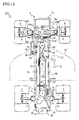
- Rear transaxle 1 is supported by a rear portion of frame 3.
- Rear transaxle 1 includes a rear transaxle housing 1H, incorporating a hydraulic pump P, a hydraulic motor M (serving as a first hydraulic motor) fluidly connected to hydraulic pump P, left and right rear wheel axles 6 (serving as a first axle), and a deceleration gear train 37 and a differential gear unit 38 (see Fig. 2) interposed between hydraulic motor M1 and axles 6.
- Rear transaxle housing 1H is outwardly opened by a pair of traveling hydraulic fluid supply-and-delivery ports 1a and 1b, which are connected to hydraulic pump P and hydraulic motor M1, respectively.
- rear transaxle housing 1H is formed with a boss to be attached to frame 3, and clamping stay 60 is fixed onto the boss.
- a hydraulic power steering valve 80 shown in Fig. 2 is disposed on frame 3 between rear and front transaxles 1 and 2.
- Rear transaxle housing 1H is rearwardly outwardly opened by auxiliary device driving hydraulic fluid supply-and-delivery ports 75 and 76.
- a pair of power steering hydraulic pressure fluid pipes 81 and 82 are interposed between ports 75a and 76 and valve 80 along pipes 23 and 26.
- a bracket 4 is fixed on the front portion of frame 3, and front transaxle housing 2H is swingably supported by bracket 4 through fore-and-aft horizontal center pivot 5, so that left and right ends of front transaxle housing 2H are vertically swingable.
- Left and right axles 6 are extended laterally outward from rear transaxle housing 1H, and fixed at distal ends thereof to center portions of unsteerable rear wheels 7, respectively.
- Left and right axles 8 are extended laterally outward from front transaxle housing 2H, and drivingly connected at distal ends thereof to steerable front wheels 9, respectively,
- mower unit 20 incorporating rotary blades 20a is vertically movably suspended under frame 3 between front wheels 9 and rear wheels 7.
- Mower unit 20 is provided at the top thereof with an input pulley 20b.
- a mower-driving belt (not shown) is looped over pulleys 10c and 20b so as to constitute the mower-driving power transmission system for drivingly connecting rotary blades 20a in mower unit 20 to engine 10.
- Electromagnetic clutch 10e interposed between pulley 10c and engine output shaft 10a is clutched on for transmitting power of engine 10 to mower unit 20, and clutched off for isolating mower unit 20 from the power of engine 10.
- a drive mode switching valve (not shown) for setting vehicle 100 into either a two-wheel drive mode or a four-wheel drive mode may be interposed between transaxles 1 and 2 across pipes 23 and 26.
- pipes 23 and 26 are entirely passed through the valve between ports 1a and 2a and between 1b and 2b, respectively, thereby circulating fluid from hydraulic pump P through hydraulic motor M1, M2 and M3.
- the valve when set at the two-wheel drive mode position makes a closed circuit between hydraulic pump P and hydraulic motor M isolated from ports 2a and 2b, so as to supply fluid from hydraulic pump P to hydraulic motor M1, thereby driving rear wheels 7 (axles 6), and the valve also makes a closed circuit between hydraulic motors M2 and M3 independent of the circuit between hydraulic pump P and hydraulic motor M1, so as to allow circulation of fluid between hydraulic motors M2 and M3, thereby allowing free differential rotation of front wheels 9.
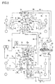
- Charge pump 33 is disposed in rear transaxle housing 1H so as to supply fluid to HST circuit HCl, and preferably driven by input shaft 17 which also serves as the pump shaft of hydraulic pump P.
- a suction line 31 is interposed between a fluid filter 32 submerged in the fluid sump and charge pump 33 so as to supply fluid to charge pump 33, Alternatively, charge pump 33 may suck fluid from reservoir tank 28 disposed outside rear transaxle housing 1H.
- a charge fluid passage 34 is extended from charge pump 33 and bifurcates to be connected to passages 21 and 27 with hydraulic pump P therebetween.
- a pair of check valves 36 are disposed on the bifurcating portions of charge fluid passage 34 connected to respective passages 21 and 27. Due to this structure, fluid delivered from charge pump 33 is introduced through corresponding check valve 36 into one of passages 21 and 27 which is pressurized lower than the other passage 27 or 21.
- a check valve 39 for preventing cavitation is connected in parallel with charge pump 33 to suction line 31, and connected to charge fluid passage 34 between charge check valves 35 through a later-discussed power steering hydraulic fluid circuit.
- check valve 39 introduces fluid from suction line 31 to depressed passage 21 or 27 so as to assist the fluid supply from charge pump 33.
- a check valve is connected to a portion of HST circuit HCl, which serves as a suction part of hydraulic motors M2 and M3 (the series of passages 22, 23 and 24 (24a and 24b) between hydraulic motor M1 and the pair of hydraulic motors M2 and M3 during forward traveling of vehicle 100, or the series of passages 21, 27, 26 and 25 (25a and 25b) between hydraulic motor M1 and the pair of hydraulic motors M2 and M3 through hydraulic pump P during backward traveling of vehicle 100), so as to supply fluid into HST circuit HC 1 from the outside of HST circuit HCl.
- the series of passages 22, 23 and 24 (24a and 24b) between hydraulic motor M1 and the pair of hydraulic motors M2 and M3 during forward traveling of vehicle 100 or the series of passages 21, 27, 26 and 25 (25a and 25b) between hydraulic motor M1 and the pair of hydraulic motors M2 and M3 through hydraulic pump P during backward traveling of vehicle 100
- Cam mechanism CM is disposed on the rear portion of front transaxle 2.
- a piston rod 90 of a power steering cylinder 79 is telescoped through the later-discussed power steering hydraulic circuit.
- the movement of piston rod 90 is transmitted to a left front wheel support unit 48L so as to laterally turn left front wheel 9 with left front wheel support unit 48L.
- the lateral turn of left front wheel 9 is transmitted to a right front wheel support unit 48R through a tie rod 49 so as to laterally turn right front wheel 9 with right front wheel support unit 48R in the same direction with left front wheel 9.
- the lateral turn of right front wheel support unit 48R is transmitted to cam mechanism CM through a control link 46.
- FIG. 5 The above-mentioned arrangement of pipes 23 and 26 is associated with the rightwardly outward opened ports 1a and 1b on the right side of rear transaxle 1.
- ports 1a and 1b are opened leftwardly outward on the left side of rear transaxle 1, i.e., on the same lateral side of vehicle 100 with ports 2a and 2b of front transaxle 2.
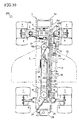
- rear rigid pipes 23b and 26b are bent upwardly forward from rear ends thereof connected to ports 1 a and 1b of rear transaxle 1, and bent again so as to be extended horizontally forward along left side plate 3L (along the bottom edge of left side plate 3L when viewed in side, and along the inside surface of left side plate 3L when viewed in plan).
- the arrangement of pipes 23 and 26 between swivel joints 54 and ports 2a and 2b is similar to the arrangement when ports 1a and 1b are disposed on the right side of rear transaxle 1.
- a port block PB is fixed onto the right side surface of rear transaxle housing 1H.
- Port block PB is bored with L-like shaped end portions of passages 22, 27, 98 and 99 (see Fig. 2).
- Ports 1a and 1b at front ends of respective passages 22 and 27, and ports 75 and 76 at front ends of respective passages 98 and 99 are forwardly outward opened on the front end surface of port block PB.
- the space within port block PB required for rightward-to-forward course change of passages 22, 27, 98 and 99 is smaller than the space required for rightward-to-forward course change of external pipes 23 (23b), 26 (26b), 81 and 82, i.e., for curving or bending the external pipes.
- reservoir tank 28 in vehicle 100 will be described.
- vehicle 100 shown in Figs. 1 and 3 (also in the cases of Figs. 5, 6 and 7), reservoir tank 28 is disposed just behind the rear end surface of frame 3, and disposed in rear cover 15, so that the fluid level in reservoir tank 28 is higher than the fluid levels of the respective fluid sumps in front and rear transaxle housings 1H and 2H.
- pipes 23 and 26 comprise flexible hoses (such as pressure rubber hoses) 23d and 26d and rigid pipes (such as metal or steel pipes) 23e and 26e.
- Flexible hoses 23d and 26d are connected to respective ports 2a and 2b of front transaxle 2.
- Rigid pipes 23e and 26e include the fore-and-aft main portion of pipes 23 and 26 and are connected to ports 1a and 1b of rear transaxle 1.
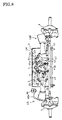
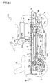
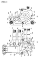
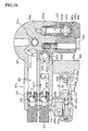
- Variable displacement hydraulic pump P having input shaft 17 serving as the vertical rotary axis thereof, is vertically mounted onto a rear top surface of center section 101 at which kidney ports 57a and 57b are opened.
- Fixed displacement hydraulic motor M1 having a laterally (leftward) horizontal motor shaft 127 serving as the rotary axis thereof, is mounted onto a front left side surface of center section 101 at which kidney ports 56a and 56b are opened, so as to be fluidly connected to hydraulic pump P.
- Motor shaft 127 is drivingly connected to deceleration gear train 37 so as to transmit the output force of hydraulic motor M1 to axles 6 through deceleration gear train 37 and differential gear unit 38.
- vertical input shaft 17 penetrates center section 101 and is inserted into charge pump casing 102 attached to the bottom surface of center section 101 so as to serve as the drive shaft of charge pump 33 in charge pump casing 102,
- Charge pump 33 sucks fluid from the fluid sump in rear transaxle housing 1H so as to supply fluid to the axle-driving hydraulic circuit, and to the auxiliary device (power steering) driving hydraulic circuit through ports 75 and 76.
- Pistons 109 are reciprocally slidably fitted in the respective cylinder holes of cylinder block 104, and project at heads thereof outward from cylinder block 104 so as to abut against movable swash plate Pa.
- Input shaft 17 projects upward from cylinder block 104, freely penetrates movable swash plate Pa, and projects upward from the top wall of rear transaxle housing 1H so as to be fixedly provided thereon with pulley 17a and cooling fan 17b, as mentioned above.
- Input shaft 17 inserted in shaft hole 17n also projects downward from center section 101 into charge pump casing 102 so as to serve as the drive shaft of charge pump 33.
- Fluid passage hole 27c is opened downward at the bottom surface of center section 101 so as to be directly coaxially connected to vertical fluid passage hole 27b bored in charge pump casing 102.
- the circular front left side surface of center section 101, onto which hydraulic motor M1 is mounted, serves as a motor contact surface 129.
- motor contact surface 129 rear motor kidney port 56a and front motor kidney port 56b are symmetrically opened leftward, and a lateral horizontal shaft hole 127a, into which motor shaft 127 is rotatably inserted, is opened leftward between rear and front motor kidney ports 56a and 56b.
- a cylinder block 120 of hydraulic motor M1 is slidably rotatably fitted onto motor contact surface 129 so as to open cylinder holes therein to motor kidney ports 56a and 56b, and is not-relatively rotatably fitted on motor shaft 127 inserted in shaft hole 127a (in a spline-engaging manner).
- motor shaft 127 rotatably fitted at a right end portion thereof in shaft hole 127a of center section 101, is journalled through a bearing 128 by the partition wall between the hydraulic circuit chamber and the transmission gear chamber, and extended at a left end portion thereof into the transmission gear chamber so as to be provided thereon with a gear 127b and a brake disc 140.
- center section 101 is bored in a rear portion thereof with a vertical fluid passage hole serving as passage 34, and provided therein with upper and lower charge check valves 35 interposed between fluid passage hole 34 and respective upper and lower parallel fluid passage holes 21 and 27d.
- Each of charge check valves 35 allows only flow from fluid from fluid passage hole (passage) 34 to corresponding fluid passage hole (passage) 21 or 27d (i.e., prevents backflow to fluid passage hole 34).
- Fluid passage hole 34 is opened downward at the bottom surface of center section 101, and connected an upwardly opened fluid passage hole 99c of passage 99 bored in charge pump casing 102.
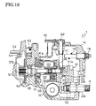
- FIG. 18 As mentioned above, upwardly opened vertical fluid passage hole 22b and 27b are bored in charge pump casing 102 so as to be coaxially connected to respective vertical fluid passage holes 22c and 27c bored in center section 101.
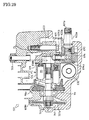
- FIGs. 18, 19, 20 and 24(a) front and rear laterally horizontal j oint plugs 22a and 27a are screwed into charge pump casing 102 so as to be connected to respective fluid passage holes 22b and 27b.
- charge pump casing 102 is bored with a vertical circular cylindrical trochoid gear chamber 137 which is opened upward to face the bottom surface of center section 101.
- a circular (in plan view) shaft hole 137a into which the lower portion of input shaft 17 is rotatably inserted, is extended downward from a bottom center portion of trochoid gear chamber 137.
- Charge pump casing 102 is bored from the bottom surface of trochoid gear chamber 137 with a vertical suction port 58a on the left side of shaft hole 137a, and with a vertical delivery port 58b on the right side of shaft hole 137a.
- a trochoid gear consisting of an inner gear 135 and an outer gear 136 is disposed in gear chamber 137.
- Inner gear 135 is fixed on input shaft 17 inserted in shaft hole 137a, so as to be rotatable integrally with input shaft 17.
- a lateral horizontal fluid passage hole 98b serving as a part of passage 98 is bored in charge pump casing 102, connected at a left end thereof to delivery port 58b, and connected at a right end thereof to a lateral horizontal joint plug 98a screwed into charge pump casing 102.
- a right end portion of joint plug 98a projects rightwardly outward from the right side surface of charge pump casing 102, and from the right side surface of rear transaxle housing 1H, so as to be provided with rightwardly outward opened port 75.
- passage 98 interposed between the delivery port of charge pump 33 and port 75 is constituted by fluid passage hole 98b and joint plug 98a, Referring to Figs.
- check valve 39 is disposed at a front end portion of fluid passage hole 99c.
- a fluid passage hole 50a is extended from an intermediate portion of fluid passage hole 99c to relief valve 50.
- a fluid passage hole 36b from a relief valve 36 is connected to a bottom portion of fluid passage hole 99c joining fluid passage hole 99b.
- Check valve 39, relief valve 50 and relief valve 36 will be detailed later.
- a horizontal control shaft 113 rotatably penetrates a right side wall of rear transaxle housing 1H.
- a control arm 114 is fixed on an inner end of control shaft 113 inside housing 1H and engages at a top portion thereof with swash plate Pa.
- Speed control lever 14 operatively connected to speed control pedal 13 is fixed on control arm 114 outside housing 1H.
- a torque spring 115 is wound around control shaft. 113 inside housing 1H and includes twisted and extended opposite end portions, so as to pinch a pin (not shown) fixed on control arm 114 and a retaining pin 117 planted into the right side wall of housing 1H.
- retaining pin 117 projects outward from housing 1H so as to be provided thereon with a nut 116 for fastening retaining pin 117 to housing 1H, Unless speed control pedal 13 is depressed, the force of spring 115 pinching both retaining pin 117 and the pin fixed on arm 114 keeps swash plate Ma at the neutral position.
- swash plate Pa When speed control pedal 13 is depressed on either front or rear side thereof, swash plate Pa is tilted integrally with the rotation of lever 14, shaft 113 and arm 114 so that spring 115 pushes the pin fixed on arm 114 at one end thereof away from retaining pin 117 retaining the other end thereof, so as to generate the neutral-returning biasing force. Due to the neutral-returning biasing force of spring 115, swash plate Pa is kept at the tilt position corresponding to the depression angle and direction of speed control pedal 13, and, if speed control pedal 13 is released from depression force, swash plate Pa and speed control pedal 13 return to the respective neutral positions.
- cylinder block 104 is rotated integrally with input shaft 17 so as to reciprocate pitons 109 at a stroke corresponding to the tilt angle of movable swash plate Pa, whereby hydraulic pump P sucks fluid from right pump kidney port 57a into the cylinder holes of cylinder block 104, and delivers fluid from the cylinder holes to left pump kidney port 57b.
- fluid in pump kidney port 57b from hydraulic pump P is led to port 1b through passage 27 consisting of fluid passage holes 27e, 27d, 27c and 27b and joint plug 27a.
- corresponding charge check valve 35 prevents high-pressurized fluid in passage 27 from entering charge fluid passage 34.
- fluid is introduced into front motor kidney port 56b through passage 22 consisting of joint plug 22a and fluid passage holes 22b, 22c and 22d.
- fluid is introduced from front motor kidney port 56b into the cylinder holes of cylinder block 120 of hydraulic motor M1 so as to reciprocate pitons 123 at a stroke corresponding to the tilt angle of fixed swash plate Ma, thereby rotating cylinder block 120 with motor shaft 127 for forward traveling rotation.
- the fluid in the cylinder holes of cylinder block 120 is delivered into rear motor kidney port 56a, and returns through passage 21 to right pump kidney port 57a serving as the suction port of hydraulic pump P.
- corresponding charge check valve 35 prevents high-pressurized fluid in passage 21 from entering charge fluid passage 34.
- check valve 39 is disposed at the front end of fluid passage hole 99c in charge pump casing 102.
- a vertical fluid passage hole 39a is extended downward from check valve 39, and a leftwardly horizontal fluid passage hole 39b is extended leftward from a bottom portion of vertical fluid passage hole 39a, so as to be connected to suction passage hole 31.
- Horizontal lever 161 is fixed on a top portion of camshaft 162 projecting upward from rear transaxle housing 1H.
- wheels 7 and 9 are requested to rotate freely from the hydraulic pressure in HST circuit HCl. Therefore, lever 161 is manually rotated together with camshaft 162 so that the cam portion of camshaft 162 thrusts pushpin 163 outward from motor contact surface 129, thereby pushing and separating cylinder block 120 from motor contact surface 129, and draining fluid from motor kidney ports 56a and 56b to the fluid sump in rear transaxle housing 1H. In this way, fluid in HST circuit HCl is reduced so as to allow the free rotation of wheels 7 and 9.
- Rear transaxle 1 is provided with a mechanism for expanding the neutral dead zone of hydraulic pump P relative to the tilt of movable swash plate Pa.
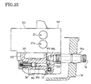
- upper and lower horizontal fluid passage holes 171 and 172 are extended rightward from respective upper and lower fluid passage holes 21 and 27d, and opened rightwardly outward at the right side surface of center section 101.
- a pair of upper and lower plugs provided at right end portions with respective rightwardly outward opened orifices 171a and 172a are fitted leftward into upper and lower fluid passage holes 171 and 172, and project at the right end portions thereof from the right openings of fluid passage holes 171 and 172 on the right side surface of center section 101.
- control arm 114 opposite to the end engaged to swash plate Pa with respect to control shaft 113 is extended so as to abut against the right end of the plugs.
- a groove 114a constantly opened to the fluid sump in rear transaxle housing 1H is formed on the surface of the extended portion of control arm 114 facing the plugs so as to correspond to a tilt range of swash plate Pa for making the expanded neutral dead zone of hydraulic pump P.
- the tilt angle of movable swash plate Pa with control arm 114 from the neutral position is increased so as to take groove 114a apart from both orifices 171 a and 172a, both the right end openings of orifices 171a and 172a are closed by the surface of the extended portion of control arm 114 so as to prevent fluid from being drained from higher-pressurized passage 21 or 27, thereby ensuring the proper volumetric efficiency between hydraulic pump P and hydraulic motors M1, M2 and M3.
- a passage 77d is disposed in rear transaxle housing 1H, and interposed between hydraulic motor M1 and port 77c.
- An external pipe 77b is disposed outside of pump housing PH and rear transaxle housing 1H, and interposed between ports 77a and 77c.
- Ports 75 and 76 connected to respective external pipes 81 and 82 are disposed on the same outer side surface of pump housing PH with port 1a.
- pump housing PH are disposed the charge fluid circuit portion between fluid filter 32 and port 75 through charge pump 33 and passage 98, the charge fluid circuit portion between port 76 and passages 21 and 27 through passage 99 and charge check valves 35, and associate valves and equipments, which are disposed in rear transaxle housing 1H in the embodiment of Fig. 2.
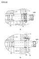
- each of the plug holes within the wall of rear transaxle housing 1H is tapped, and each of joint plugs 22a and 27a has an intermediate threaded portion corresponding to the tapped plug hole, so as to be immovably fastened to rear axle housing 1 H, while each of joint plugs 22a and 27a are slidably fitted into charge pump casing 102. Due to the screw-engagement of joint plugs 22a and 27a to rear transaxle housing 1H, joint plugs 22a and 27a are prevented from being axially deviated by movement of pipes 23 and 26 according to the swing of front transaxle 2 around center pivot 5, thereby preventing fluid leak from the gap between O-ring 175 and the peripheral wall surface of the shaft hole in rear transaxle housing 1H.
- vehicle 200 is provided with front transaxle 2 in which positions or directions of ports 2a and 2b are different from those of front transaxle 2 of vehicle 100.
- vehicle 200 according to a second embodiment is provided with front transaxle 2 serving as laterally reversed front transaxle 2 of vehicle 100.
- right fixed displacement hydraulic motor M2 and left variable displacement hydraulic motor M3 are disposed in front transaxle housing 2H.
- cam mechanism CM for controlling the tilt of swash plate M3 a of hydraulic motor M3 is disposed leftward in front transaxle 2.
- Ports 2a and 2b are disposed on a laterally intermediate rear potion of rear transaxle housing 2H so as to be rightwardly outward opened. Further, referring to Fig. 10, ports 1a and 1b are disposed on the right side surface of rear transaxle housing 1H. Vehicle 200 employs HST circuit HC1 I similar to that of Fig. 2.
- Rear rigid pipes 23b and 26b are extended rightward from respective ports 1a and 1b, bent and extended forwardly upward, and bent against and extended horizontally forward, so as to be clamped by clamping stay 62 fixed on the inside surface of right side plate 3R.
- Front rigid pipes 23c and 26c are extended in the fore-and-aft direction along right side plate 3R of frame 3 (along the bottom edge of right side plate 3R when viewed in side, and along the inside surface of right side plate 3R when viewed in plan), and connected to respective rear rigid pipes 23b and 26b through respective swivel joints 54, and to respective front rigid pipes 23c and 26c through respective swivel joints 55.
- This arrangement of pipes 23 and 26 between rear and front transaxles 1 and 2 has the same advantages as the arrangement of pipes 23 and 26 shown in the embodiment of Fig, 3 combined with the embodiment of Fig. S, That is, pipes 23 and 26 can be compactly disposed at the safe space inside frame 3 while they are prevented from interfering with the traveling power transmission system, the mower-driving power transmission system and mower unit 20, from having fluid leak and being damaged at ends thereof connected to ports 1a, 1b, 2a and 2b, and from being subjected to twisting stress caused by the swing of front transaxle 2 around center pivot 5.
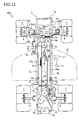
- ports 1a and 1b are disposed on the right side surface of rear transaxle housing 1H, Referring to Figs. 12 and 13, to correspond to this arrangement of ports 1a, 1b, 2a and 2b, arrangement of pipe 23 interposed between ports 1 a and 2a is similar to that of vehicle 100 shown in Fig. 3, and arrangement of pipe 26 interposed between ports 1b and 2b is similar to that of vehicle 200 shown in Fig. 10.
- pipe 23 includes the fore-and-aft main portion extended along left side plate 3L (along the bottom edge of left side plate 3L when viewed in side and along the inside surface of left side plate 3L when viewed in plan), and pipe 26 includes the fore-and-aft main portion extended along right side plate 3R (along the bottom edge of right side plate 3R when viewed in side and along the inside surface of right side plate 3R when viewed in plan).
- pipe 23 In association with the laterally opposite arrangement of ports 1a and 2a, pipe 23 includes the lateral extended portion disposed just in front of rear transaxle housing 1H (and clamped by clamping stay 60 fixed on rear transaxle housing 1H) so as to be extended at the fore-and-aft main portion thereof along left side plate 3L.
- pipe 26 is extended from port 1b to the fore-and-aft main portion thereof without bending to have a lateral extended portion just in front of rear transaxle housing 1H.
- pipe 23 comprises rear and front rigid pipes 23b and 23c and flexible hose 23a interposed between rigid pipes 23b and 23c
- pipe 26 comprises rear and front rigid pipes 26b and 26c and flexible hose 26a interposed between rigid pipes 26b and 26c.
- Flexible hose 23a is extended in the fore-and-aft direction along left side plate 3L, connected at the rear end thereof through swivel joint 54 to rear rigid pipe 23b connected to port 1a, and connected at the front end thereof through swivel joint 55 to front rigid pipe 23c connected to port 2a
- Flexible hose 26a is extended in the fore-and-aft direction along right side plate 3R, connected at the rear end thereof through swivel joint 54 to rear rigid pipe 26b connected to port 1b, and connected at the front end thereof through swivel joint 55 to front rigid pipe 26c connected to port 2b.
- Rear rigid pipe 23b includes the lateral extended portion which is disposed just in front of rear transaxle housing 1H and clamped by clamping stay 60 fixed on rear transaxle housing 1H.
- the forwardly extended front portion of rear rigid pipe 23b is clamped by clamping stay 61 fixed to left side plate 3L so as to be connected to flexible hole 23a through swivel joint 54.
- Rear rigid pipe 26b includes no lateral extended portion disposed just in front of rear transaxle housing 1H, but is extended substantially forward when viewed in plan so as to be connected to flexible hose 26R through swivel joint 54.
- pipe 23 comprises flexible hose 23d connected to port 2a, and rigid pipe 23e connected to port 1a.
- Pipe 26 comprises flexible hose 26d connected to port 2b, and rigid pipe 26e connected to port 1b.
- Rigid pipe 23e includes the fore-and-aft extended portion along left side plate 3L, and is connected at the rear end thereof to port 1a, and at the front end thereof to flexible hose 23d through swivel joint 55.
- rigid pipe 23e includes the lateral extended portion which is disposed just in front of rear transaxle housing 1H and clamped by clamping stay 60 fixed on rear transaxle housing 1H.
- Rigid pipe 26e includes the fore-and-aft extended portion along right side plate 3R, and is connected at the rear end thereof to port 1b, and at the front end thereof to flexible hose 26d through swivel joint 55.
- Rigid pipe 26e includes no lateral extended portion disposed just in front of rear transaxle housing 1H, but is extended substantially forward when viewed in plan so as to be disposed along right side plate 3R, and connected at the front end thereof to flexible hose 26d through swivel joint 55.
- power steering device 80 is disposed between rear and front transaxles 1 and 2
- power steering cylinder 79 is disposed along left side plate 3L and includes piston rod 90 connected to bracket 48a mounted on left front wheel support unit 48L.
- Ports 76 and 78 are disposed on the same right side surface of rear transaxle housing 1H with ports 1 a and 1b.
- pipes 81 and 82 interposed between valve 80 and respective ports 75 and 76, and pipes 83 and 84 interposed between valve 80 and cylinder 79 are disposed similar to those in the arrangement of Fig. 3.
- pipes 81 and 82 are disposed along pipe 26 along right side plate 3R.
- the features and advantages of the arrangement of power steering pipes are the same as those in the above description of Fig. 3.
- Each of hereinafter described vehicles 400 and 500 is provided with a reservoir tank arranged in a different manner from that of reservoir tank 28 in vehicle 100.
- a reservoir tank 428 is joined to a fuel tank FT.
- Fuel tank FT and reservoir tank 428 are disposed between rear transaxle 1 and driver's seat 16 above rear transaxle 1, i.e., below driver's seat 16 and above rear transaxle 1.
- a tank 451 whose inner space is divided into front and rear chambers by a partition 450.
- the front chamber in tank 451 serves as fuel tank FT.
- the rear chamber serves as reservoir tank 428, which is disposed just behind seat 16 mounted on the top of rear cover 15 in the fore-and-aft direction of vehicle 400.
- the top portion of rear cover 15 is bored with a hole just behind seat 16.
- An upright cylindrical fluid-supply portion 428a projects upward from tank 428 through the hole of rear cover 15 just behind seat 16.
- Breather 442 is provided on the top of fluid-supply portion 428a.
- Fluid-supply portion 428a is opened at the bottom thereof to fluid tank 428 in tank 451.
- a fuel-supply opening is disposed on the top of fuel tank FT of tank 451 under seat 16.
- Reservoir tank 428 is disposed so that the fluid level in reservoir tank 428 is higher than the fluid levels of the respective fluid sumps in rear and front transaxles 1 and 2.
- vehicle 400 is provided with left and right mower hangers 491 whose respective pivots 92 are disposed coaxially to axles 8 supported by rear transaxle housing 2H.
- Mower hangers 491 are pivoted at top portions thereof on respective pivots 92, and extended downward.
- Left and right link rods 91 a are pivoted at front ends thereof onto bottom portions of mower hangers 491, and hooked at rear ends thereof onto the front end of mower unit 20. Since pivots 92 of mower hangers 491 are disposed coaxially to axles 8, the accuracy of location of mower hangers 491 is improved so as to facilitate assembly work of suspending mower unit 20.
- reservoir tank 528 is disposed upright just behind engine 10 between front wheels 9 and rear wheels 7.
- the bottom of reservoir tank 528 is disposed at the vertical intermediate position of the inside of bonnet 11.
- a cylindrical upright fluid-supply portion 528a projects upward from the top of reservoir tank 528.
- a breather 542, also serve as a fluid-supply opening of reservoir tank 528, is disposed on the top of fluid-supply portion 528a so as to face the opening of the dashboard covered with lid 543.
- Reservoir tank 528 is fluidly connected to the fluid sump of rear transaxle 1 through drain pipe 29, and to the fluid sump of front transaxle 2 through drain pipe 30, so as to absorb excessive fluid from the respective fluid sumps.
- reservoir tank 528 Since reservoir tank 528 is disposed between rear wheels 7 and front wheels 9, reservoir tank 528 approaches the fore-and-aft middle portion of vehicle 500 so as to ensure good balance of vehicle 500 in the fore-and-aft direction. Due to the upright shape of reservoir tank 528, the fluid in reservoir tank 528 is prevented from being contaminated with air bubbles when vehicle 500 travels on a slope. Further, reservoir tank 528 disposed just behind engine 10 is easily subjected to the air for cooling engine 10.
- vehicle 500 is provided with mower hangers 491 pivoted on pivots 92 disposed coaxially to axles 8, so as to suspend mower unit 20 through link rods 91a, similar to those of vehicle 400 in Fig. 14.
- the arrangement of fixed displacement hydraulic motor M2 and variable displacement hydraulic motor M3 for respective axles 8 may be replaced with an arrangement of a single (variable displacement) hydraulic motor and a differential gear unit driven by the hydraulic motor.
- Left and right axles 8 mutually connected through the differential gear unit can be differentially driven similar left and right axles 8 driven by respective hydraulic motors M2 and M3.
- the single variable displacement hydraulic motor ensures acceleration of front wheels 9 during turning of the vehicle.
- a pair of hydraulic pressure fluid supply-and-delivery ports of the single hydraulic motor, and pipes interposed between these ports and ports 1a and 1b on rear transaxle 1 can be disposed on front transaxle housing 2H similar to any of the foregoing arrangements of ports 2a and 2b and pipes 23 and 26.
- transaxle 601 may replace rear transaxle 1 in the foregoing embodiments of vehicles 100 to 500 referring to Figs. 1 to 24.
- transaxle 601 includes housing 601H which is provided on a right side surface thereof with ports 601a and 601b for supply and delivery of hydraulic pressure fluid for driving axles, and with ports 675 and 676 for supply and delivery of hydraulic pressure fluid for driving an auxiliary (e.g., power steering) device.
- a hydraulic circuit of a hydraulic four-wheel driving vehicle equipped with transaxle 601 can be similar to the hydraulic circuit shown in Fig.
- transaxle 601 The main feature of transaxle 601 is that an adapter 693, formed therein with a fluid passage hole to be interposed between port 601 a and a passage in a center section 691, is detachably attached to center section 691, as shown in Flgs, 28 and 29, and a joint plug 627a including port 601b is fitted into center section 691 to be connected to another passage in center section 691, as shown in Figs. 28 and 32(b).
- transaxle 601 A general structure and function of transaxle 601 will be described. As shown in Fig. 27, the inner space of transaxle housing 601H is partitioned by a partition wall between a hydraulic circuit chamber and a transmission gear chamber.
- transaxle housing 601H is constituted by upper and lower halves joined to each other through bolts 653.
- fixed displacement hydraulic motor M6 having a laterally (leftward) horizontal motor shaft 727 serving as the rotary axis thereof, is mounted onto a front left side surface of center section 691 at which kidney ports 656a and 656b are opened, so as to be fluidly connected to hydraulic pump P6,
- Motor shaft 727 is drivingly connected to deceleration gear train 637 so as to transmit the output force of hydraulic motor M6 to axles 6 through deceleration gear train 637 and differential gear unit 638.
- vertical input shaft 617 penetrates center section 691 and is inserted into a charge pump casing 692 attached to the bottom surface of center section 691 so as to serve as the drive shaft of charge pump 633 in charge pump casing 692.
- Charge pump 633 sucks fluid from the fluid sump in transaxle housing 601H so as to supply fluid to the axle-driving hydraulic circuit, and to the auxiliary device (power steering) driving hydraulic circuit through ports 675 and 676.
- speed control lever 614 operatively connected to speed control pedal 13 is pivoted on transaxle housing 601 H so as to control the tilt angle and direction of a movable swash plate P6a of hydraulic pump P6,
- center section 691 is fastened to an inside wall of transaxle housing 601H through bolts 651.
- the circular rear top surface of center section 691, onto which hydraulic pump P6 is mounted serves as a pump contact surface 603.
- a right pump kidney port 657a and a left pump kidney port 657b are laterally symmetrically opened upward, and a vertical shaft hole 617n, into which input shaft 617 is rotatably inserted, is opened upward between right and left pump kidney ports 657a and 657b.
- Vertical shaft hole 617n is passed through center section 691 and also opened downward at the bottom surface of center section 691, as shown in Fig. 30.
- a cylinder block 604 of hydraulic pump P6 is slidably rotatably fitted onto pump contact surface 603 so as to open cylinder holes therein to kidney ports 657a and 657b, and is not-relatively rotatably fitted on input shaft 617 passed through shaft hole 617n (in a spline-engaging manner).
- Pistons 609 are reciprocally slidably fitted in the respective cylinder holes of cylinder block 604, and project at heads thereof outward from cylinder block 604 so as to abut against movable swash plate P6a.
- Input shaft 617 projects upward from cylinder block 604, freely penetrates movable swash plate P6a, and projects upward from the top wall of rear transaxle housing 1H so as to be fixedly provided thereon with pulley 617a and cooling fan 617b, as mentioned above.
- Input shaft 617 inserted in shaft hole 617n also projects downward from center section 691 into charge pump casing 692 so as to serve as the drive shaft of charge pump 633.
- Fluid passage hole 627e is extended rightwardly downward from left pump kidney port 657b to a fore-and-aft intermediate portion of fluid passage hole 627d. Fluid passage hole 627d is fore-and-aft horizontally extended under fluid passage hole 621 in parallel. Fluid passage hole 627b is extended horizontally rightward from a front end portion of fluid passage hole 627d, and opened outward at a right side surface of center section 691, Joint plug 627a provided at the outer end with port 601b is inserted horizontally leftward into fluid passage hole 627b through a right sidewall of transaxle housing 601H, so as to be fluidly connected to left pump kidney port 657b.
- the circular front left side surface of center section 291, onto which hydraulic motor M6 is mounted serves as a motor contact surface 729.
- motor contact surface 729 rear motor kidney port 756a and front motor kidney port 756b are symmetrically opened leftward, and a lateral horizontal shaft hole 727a, into which motor shaft 727 is rotatably inserted, is opened leftward between rear and front motor kidney ports 656a and 656b.
- a cylinder block 720 of hydraulic motor M6 is slidably rotatably fitted onto motor contact surface 729 so as to open cylinder holes therein to kidney ports 656a and 656b, and is not-relatively rotatably fitted on motor shaft 727 inserted in shaft hole 727a (in a spline-engaging manner).
- Pistons 723 are reciprocally slidably fitted in the respective cylinder holes of cylinder block 720, and project at heads thereof outward from cylinder block 720 so as to abut against a fixed swash plate M6a.
- rear motor kidney port 656a is connected to right pump kidney port 657a through horizontal fluid passage hole (passage) 621, as mentioned above.
- Joint plug 622a is screwed from the rightward outside of housing 601H into the horizontal tapped hole in adapter 622a through the right side wall of transaxle housing 601H.
- Joint plug 622a includes a horizontal penetrating axial fluid passage hole whose outer right end serves as port 601a.
- the fluid passage hole in joint plug 622a is opened at the inward end into hole 694a so as to be fluidly connected to vertical fluid passage hole 622b in plug 694, thereby fluidly connecting port 601a to motor kidney port 656b opened to hydraulic motor M6.
- adapter 693 may be formed therein with a fluid passage without fluid passage plug 694, Alternatively, both fluid passages to respective ports 601 a and 601b may be formed in adapter 693. Alternatively, adapter 693 may be formed therein with a fluid passage to port 641b, and a joint plug including port 601 a may be provided onto center section 691.
- Joint plugs 622a and 627a are screwed into the tapped hole in adapter 693 and tapped fluid passage hole 627b, respectively.
- joint plugs 622a and 627a may be screwed in respective tapped holes within The wall of transaxle housing 601H, similar to joint plug 22a (27a) of Fig. 33(a), or they may be fastened to the outer side surface of transaxle housing 601H through a flange, thereby improving the fluid tightness thereof.
- joint plugs 622a and 627a may be just slidably fitted into the hole in adapter 693 and fluid passage hole 627b, respectively (without screwing engagement).
- center section 691 is bored in a rear portion thereof with a vertical fluid passage hole 634, and provided therein with upper and lower charge check valves 635 interposed between fluid passage hole 634 and respective upper and lower parallel fluid passage holes 621 and 627d.
- charge check valves 635 allows only flow from fluid from fluid passage hole 634 to corresponding fluid passage hole 21 or 27d (i.e., prevents backflow to fluid passage hole 634).
- Fluid passage hole 634 is opened downward at the bottom surface of center section 691, and connected an upwardly opened fluid passage hole 699d bored in charge pump casing 692.
- Charge pump casing 692 is bored from the bottom surface of trochoid gear chamber 737 with a vertical suction port 658a on the left side of shaft hole 737a, and with a vertical delivery port 658b on the right side of shaft hole 737a.
- a trochoid gear consisting of an inner gear 735 and an outer gear 736 is disposed in gear chamber 737.
- Inner gear 735 is fixed on input shaft 617 inserted in shaft hole 737a, so as to be rotatable integrally with input shaft 617.
- a lateral horizontal fluid passage hole 698b is bored in charge pump casing 692, connected at a left end thereof to delivery port 658b, and connected at a right end thereof to a lateral horizontal joint plug 698a screwed into charge pump casing 692.
- a right end portion of joint plug 698a projects rightwardly outward from the right side surface of charge pump casing 692, and from the right side surface of rear transaxle housing 601H, so as to be provided with rightwardly outward opened port 675.
- a passage (coinciding to passage 98 of transaxle 1) interposed between the delivery port of charge pump 633 and port 675 is constituted by fluid passage hole 698b and joint plug 698a.
- a downwardly opened groove of charge pump casing 691 and an upwardly opened groove of charge pump 692 along a rear side edge of trochoid gear chamber 737 coincide with each other so as to form a substantially lateral fluid passage hole 699d.
- a vertical fluid passage hole 699c is extended downward from a right end portion of fluid passage hole 699d, and connected at the bottom thereof to a lateral horizontal fluid passage hole 699b.
- Fluid passage hole 699b is opened rightwardly outward at the right side surface of charge pump casing 692.
- a joint plug 699a is screwed into fluid passage hole 699b.
- a right end portion of joint plug 699a projects rightwardly outward from the right side surface of charge pump casing 692, and from the right side surface of transaxle housing 601H, so as to be provided with rightwardly outward opened port 676 adjacent to port 675.
- fluid passage hole 634 is connected to an intermediate portion of fluid passage hole 699d.
- fluid passage hole 634 is connected to fluid passage holes 621 and 627d through respective charge check valves 635.
- joint plug 699a and fluid passage holes 699b and 699c constitute a passage (coinciding to passage 99 of transaxle 1) interposed between port 676 and either lower pressurized passage hole 621 or 627d connected to the suction side of hydraulic pump P6 through corresponding charge check valve 635.
- a check valve 639 is disposed at a left end portion of fluid passage hole 699d.
- a vertical fluid passage hole 636b is extended downward from an intermediate portion of fluid passage hole 699d to a relief valve 636.
- a fore-and-aft horizontal drain hole 636c is extended from relief valve 636 and opened outward at the rear side surface of charge pump casing 692.
- Check valve 636 absorbs excessive fluid from fluid passage hole 699d through hole 636c and drains it to the fluid sump through drain hole 636c.
- a vertical fluid passage hole 650a is extended downward from fluid passage hole 699d to a relief valve 650.
- ports 601a, 601b, 675 and 676 are disposed on the respective right outer ends of joint plugs 622a, 627a, 698a and 699a projecting rightwardly outward from the right side wall of rear transaxle housing 601H. Therefore, pipes 23, 26, 81 and 82 can be compactly collected to be connected to respective ports 601 a, 601 b, 675 and 676.
- Fig. 1 For the arrangement of vehicle 100 as shown in Fig.
- front axle-driving hydraulic fluid port 601a is disposed higher than rear axle-driving hydraulic fluid port 601b.
- port 601b is disposed rightward from port 601a. Due to this arrangement of ports 601a and 601b, pipes 23 and 27 connected to respective ports 601a and 601b are can be smoothly extended forwardly upward without stressing bend, thereby being further compactly collected. Front and rear auxiliary (power steering) device driving hydraulic fluid ports 675 and 676 are disposed at the same height.
- control lever 614 and center section 691 may be provided with a mechanism for expanding a neutral dead zone of hydraulic pump P6 relative to the tilt angle of swash plate P6a similar to the mechanism including the orifice members having orifices 171 a, 172a fitted in center section 101 and groove 114a formed in arm 114 as shown in Fig. 21.
- transaxle 601 is provided with a forcible relief valve mechanism for draining fluid from the HST circuit when the vehicle is towed or for another purpose, similar to that shown in Fig. 19.
- a forcible relief lever 761 is pivoted on housing 601H so as to operate the forcible relief valve mechanism.
- fluid passage hole 621 serves as passage 21; the fluid passage formed by center section 691, adapter 693 and fluid passage plug 694 serves as passage 22; joint pipe 627a and fluid passage holes 627b, 627d and 627e constitute passage 27; fluid passage hole 698b and joint plug 698a constitute passage 98; joint plug 699a and fluid passage holes 699b and 699c constitute passage 99; and suction fluid passage hole 631, fluid filter 632, charge pump 633, fluid passage hole 634, check valves 635, relief valve 636, check valve 639 and relief valve 650 serve as respective components 31, 32, 33, 34, 35, 36, 39 and 50.
- the drive train from hydraulic motor M6 to axles 6 in transaxle 601 is similar to that from hydraulic motor M1 to axles 6 in transaxle 1, on the assumption that motor shaft 727, gear 727b, brake disc 740, deceleration gear train 637 and differential gear unit 638 including a bull gear 63 8a and a differential side gear 638b serve as respective components 127, 127b, 140, 37, 38, 38a and 38b.
- differential gear unit 638 comprises is provided with a differential lock mechanism, as shown in Fig.
- the differential lock mechanism comprises a differential lock pin 638d and a shifter 638e, Shifter 63 8 is manually operated from the outside of transaxle housing 601H, so as to slide along (right) axle :6.
- Differential lock pin 638d integrally movably engages with shifter 638dand is axially slidably fitted in (right) differential side gear 638b.
- shifter 638e slides (leftward) so as to push differential lock pin 638d into a hole of bull gear 638a through (right) differential side gear 638b, as shown in Fig.
- shifter 638e When shifter 638e is operated for canceling the differential locking, shifter 638e slides rightward so as to withdraw differential lock pin 638d from the hole of bull gear 638b, thereby allowing differential rotation of left and right axles 6.
Landscapes
- Engineering & Computer Science (AREA)
- Chemical & Material Sciences (AREA)
- Combustion & Propulsion (AREA)
- Transportation (AREA)
- Mechanical Engineering (AREA)
- Motor Power Transmission Devices (AREA)
- Arrangement And Driving Of Transmission Devices (AREA)
Abstract
Description
- The invention relates to a hydraulically driven working vehicle, especially, a four-wheel drive working vehicle, equipped with front wheels and rear wheels driven by respective hydraulic motors, and relates to a hydraulic transaxle including the hydraulic motor applicable to the vehicle, An example of the hydraulically driven working vehicle according to the invention is a lawn tractor equipped at the middle body portion thereof with a mower unit. The transaxle according to the invention can supply fluid to hydraulic equipments equipped on the hydraulically driven vehicle, e.g., a hydraulic power steering system, in addition to the hydraulic motor for driving an axle.
- Conventionally, there are well-known hydraulic four-wheel drive working vehicles, each of which is equipped with front and rear hydraulic motors for driving front wheels and rear wheels. A hydraulic four-wheel drive working vehicle, as disclosed in
International Publication No. 2004/062956 , is provided with a rear transaxle including a hydraulic motor for driving left and right rear wheels, and with a front transaxle including a pair of left and right hydraulic motors for driving respective left and right front steerable wheels. This type hydraulic four-wheel drive working vehicle is equipped at a middle portion thereof between the front and rear transaxles with a traveling power transmission system for transmitting power from a prime mover to the rear transaxle, and with a working power transmission system for transmitting power from the prime mover to a working device, In this situation, the front and rear transaxles are fluidly connected to each other via pipes for driving the front and rear wheels (axles), and the axle-driving pipes have to be disposed at the middle portion without interfering with the traveling power transmission system and the working power transmission system. - To miniaturizing the hydraulic four-wheel drive working vehicle, the pipes are requested to be disposed within a space inside a vehicle body frame, However, the space is mainly occupied by the traveling power transmission system and the working power transmission system. Further, the vehicle may be equipped under the fore-and-aft middle portion of the vehicle body frame with a working device, such as a mower unit.
- The axle-driving pipes have to be disposed in the space between the front and rear transaxles without interfering with the traveling power transmission system and the working power transmission system, and the working device at need. Further, to facilitate assembly works, the pipes are desirably disposed so as to require no device to be detached during the piping work of the pipes, and to require no pipe to be detached during attachment of other devices. On the other hand, in order to reduce internal pressure resistance in the pipes, the pipes are requested to have reduction of bent portions therein and to have rigid pipe portions as long as possible. Especially, the pipes have to be prevented at portions thereof adjacent to a center pivot of the front transaxle with being excessively twisted or bent, and prevented at portions thereof connected to ports from having oil leak or being damaged.
- If the hydraulic four-wheel drive vehicle includes a hydraulic power steering system, hydraulic fluid pipes for the power steering system must be disposed so as to solve the same problems as the axle-driving pipes.
- Further, if the vehicle is provided with a reservoir tank for supplying fluid to the hydraulic motors in the front and rear transaxles, it is requested that the reservoir tank is disposed so as to be prevented from interfering with the traveling power transmission system and the working power transmission system, to have easy oiling and maintenance, and to effectively supply fluid into the housings of the front and rear transaxles. Especially, when the front transaxle housing is swingably supported onto the vehicle body frame via a center pivot, the reservoir tank is requested to prevent fluid therein from being contaminated with air by tilt of the fluid level surface according to the swing of the front transaxle housing, and to prevent hydraulic pressure fluid pipes between the reservoir tank and the transaxles from being twisted by the swing of the front transaxle housing,
- A first object of the invention is to provide a hydraulic four-wheel drive working vehicle with a simple hydraulic pressure piping structure solving the above problems.
- To achieve the first object, in a first aspect of the invention, a hydraulically driven working vehicle comprises: a frame including a pair of left and right side plates extended in the fore-and-aft direction of the vehicle; a first transaxle supported by one of front and rear portions of the frame, the first transaxle including a hydraulic pump, a first hydraulic motor fluidly connected to the hydraulic pump, a first axle driven by the first hydraulic motor, and a first transaxle housing incorporating the hydraulic pump, the first hydraulic motor and the first axle, wherein the first transaxle housing is provided with a pair of outwardly opened first ports fluidly connected to the hydraulic pump and the first hydraulic motor, respectively; a second transaxle supported by the other rear or front portion of the frame, the second transaxle including a second hydraulic motor fluidly connected to the hydraulic pump, a second axle driven by the second hydraulic motor, and a second transaxle housing swingably supported on the rear or front portion of the frame through a center pivot, and incorporating the second hydraulic motor and the second axle, wherein the second transaxle housing is provided with a pair of second ports fluidly connected to the second hydraulic motor; a prime mover supported by the frame between the fist and second transaxles; a traveling power transmission system supported by the frame between the prime mover and the first transaxle so as to drivingly connect the hydraulic pump to the prime mover; a working device disposed under the frame between the first and second transaxles; a working power transmission system supported by the frame between the prime mover and the working device so as to drivingly connect the working device to the prime mover; and a pair of axle-driving hydraulic pressure fluid pipes interposed between the pair of first ports and the pair of second ports so as to fluidly connect the second hydraulic motor to the hydraulic pump. The pipes include respective fore-and-aft extended portions which are extended in the fore-and-aft direction of the vehicle between an inside surface of at least one of the left and right side plates of the frame and the traveling and working power transmission systems.
- In the vehicle according to the first aspect, the axle-driving hydraulic pressure fluid pipes disposed so as not to be exposed sideward from the frame vehicle, thereby being protected from external obstacles. Consequently, the traveling performance of the vehicle can be safely maintained. Further, the vehicle has good appearance because of the hidden pipes.
- In the vehicle according to the first aspect, preferably, the fore-and-aft extended portions of both of the pipes are extended along the inside surface of one of the left and right side plate. Due to the simple arrangement of the pipes in the narrow space along the inside surface of the side plate, the vehicle can be minimized while ensuring prevention of the pipes from interfering with the traveling and working power transmission systems and the working device. Further, the piping work for this arrangement of the pipes can be easy.
- Alternatively, in the vehicle according to the first aspect, preferably, the fore-and-aft extended portion of one of the pipes is extended along the inside surface of one of the left and right side plates, and the fore-and-aft extended portion of the other pipe is extended along the inside surface of the other right or left side plate. Due to the simple arrangement of the pipes in the narrow spaces along the inside surfaces of the side plates, the vehicle can be minimized while ensuring prevention of the pipes from interfering with the traveling and working power transmission systems and the working device. Further, the piping work for this arrangement of the pipes can be easy.
- Further preferably, at least one of the pipes includes: a first rigid pipe portion connected to one of the first ports; a second rigid pipe portion connected to one of the second ports; and a flexible pipe portion interposed between the first and second rigid pipe portions. The flexible hose is extended along one of the left and right side plates of the frame. Therefore, the flexible hose can be bent or curved so as to absorb stress on the pipe according to the swing of the second transaxle around the center pivot. Consequently, the at least one pipe can be durable against the frequent swing of the second transaxle.
- Alternatively, preferably, at least one of the pipes includes: a rigid pipe portion connected to one of the first ports and extended along one of the left and right side plates of the frame; and a flexible pipe portion interposed between the rigid pipe portion and one of the second ports. Consequently, the main portion of the at least one pipe is the rigid pipe portion whose internal pressure resistance is small so as to ensure good fuel efficiency.
- In either of the above two cases where the at least one pipe uses the rigid pipe portion, preferably, a stay is supported on either the first transaxle housing or one of the left and right side plates of the frame so as to support the rigid pipe portion connected to the first port. Therefore, the stay prevents warp of the pipe caused by the swing of the second transaxle around the center pivot from being transmitted to the end of the pipe connected to the corresponding first port, thereby preventing the pipe end and the first port from having oil leak and from being damaged.
- Further preferably, the first transaxle housing includes a boss connected to the frame, and the stay is mounted onto the boss. Consequently, due to the support by the stay on the first transaxle housing, the pipe end and the first port connected to each other are further surely prevented from moving relative to each other causing the oil leak and damage. The boss ordinarily formed on the first transaxle housing serves as a fixture portion onto which the stay is fixed, thereby requiring no additional fixture member and saving costs.
- Further preferably, the at least one of the pipes further includes a swivel joint disposed between the flexible pipe portion and at least one of the first and second rigid pipe portions. The swivel joint absorbs twist of the pipe caused by the swing of the second transaxle around the center pivot, thereby inexpensively providing the pipe having high durability against the swing of the second transaxle.
- Alternatively, in the vehicle according to the first aspect, preferably, the pair of first ports are disposed at one of left and right sides of the vehicle, and the pair of second ports are disposed at the other right or left side of the vehicle. The fore-and-aft extended portion of at least one of the pipes is extended along one of the left and right side plates of the frame and connected to the second port. The at least one of the pipes further includes a laterally extended portion which is extended in the lateral direction of the vehicle between the first port and the fore-and-aft extended portion of the at least one of the pipe. A stay is fixed on the first transaxle housing so as to support the laterally extended portion of the at least one of the pipes.
- Therefore, in the case that the pair of first ports and the pair of second ports are opened laterally opposite to each other, the limited spaces along the left and right side plates are used for piping of the axle-driving pipes without interfering with another equipment, thereby miniaturizing the vehicle. Further, the stay prevents warp of the corresponding pipe caused by the swing of the second transaxle around the center pivot from being transmitted to the end of the pipe connected to the corresponding first port, thereby preventing the pipe end and the first port from having oil leak and from being damaged.
- Further preferably, the first transaxle housing includes a boss connected to the frame, and wherein the stay is mounted onto the boss. Consequently, due to the support by the stay on the first transaxle housing, the pipe end and the first port connected to each other are further surely prevented from moving relative to each other causing the oil leak and damage. The boss ordinarily formed on the first transaxle housing serves as a fixture portion onto which the stay is fixed, thereby requiring no additional fixture member and saving costs.
- Further preferably, the at least one of the pipes includes: a first rigid pipe portion connected to one of the first ports and serving as the laterally extended portion of the at least one of the pipes; a second rigid pipe portion connected to one of the second ports; and a flexible pipe portion interposed between the first and second rigid pipe portions, wherein the flexible hose is extended along one of the left and right side plates of the frame. Therefore, the flexible hose can be bent or curved so as to absorb stress on the pipe according to the swing of the second transaxle around the center pivot. Consequently, the at least one pipe can be durable against the frequent swing of the second transaxle.
- Alternatively, further preferably, the at least one of the pipes includes: a rigid pipe portion connected to one of the first ports and extended along one of the left and right side plates of the frame so as to serve as the fore-and-aft extended portion; and a flexible pipe portion interposed between the rigid pipe portion and one of the second ports. Consequently, the main portion of the at least one pipe is the rigid pipe portion whose internal pressure resistance is small so as to ensure good fuel efficiency.
- In either of the above two cases where the at least one pipe includes the rigid pipe portion and the flexible pipe portion, the at least one of the pipes further includes a swivel joint disposed between the flexible pipe portion and the first rigid pipe portion. The swivel joint absorbs twist of the pipe caused by the swing of the second transaxle around the center pivot, thereby inexpensively providing the pipe having high durability against the swing of the second transaxle.
- In the pipe arrangement when the pair of first ports and the pair of second ports are laterally offset, preferably, the fore-and-aft extended portions of both of the pipes are extended along one of the left and right side plates of the frame and connected to the respective second ports. Both of the pipes include the respective laterally extended portions interposed between the respective first ports and the respective fore-and-aft extended portions thereof. The stay supports the laterally extended portions of both of the pipes. Therefore, both of the fore-and-aft extended portions of the pipes are juxtaposed in the limited space along the side plate so as to minimize the vehicle. Further, the stay prevents warp of both of the pipes caused by the swing of the second transaxle around the center pivot from being transmitted to the ends of the pipes connected to the respective first ports, thereby preventing the pipe ends and the first ports from having oil leak and from being damaged.
- In the pipe arrangement when the pair of first ports and the pair of second ports are laterally offset, alternatively, preferably, a first pipe of the pipes is extended in the fore-and-aft direction of the vehicle from the corresponding first port along one of left and right side plates of the frame, and a second pipe of the pipes includes the fore-and-aft extended portion extended along the other right or left side plate and connected to the corresponding second port, and includes the laterally extended portion connected to the corresponding first port and supported by the stay. Therefore, the fore-and-aft extended portions of the pipes are disposed in the limited spaces along the respective left and right side plates so as to minimize the vehicle. Further, the stay prevents warp of the second pipe caused by the swing of the second transaxle around the center pivot from being transmitted to the end of the second pipe connected to the first port, thereby preventing the end of the second pipe and the first port from having oil leak and from being damaged.
- Further preferably, a stay is fixed onto the one of the left and right side plates so as to support the first pipe. The stay on the side plate prevents warp of the first pipe, which is not supported by the stay on the first transaxle housing, caused by the swing of the second transaxle around the center pivot from being transmitted to the end of the first pipe connected to the first port, thereby preventing the end of the first pipe and the first port from having oil leak and from being damaged. In the vehicle according to the first aspect, preferably, the first transaxle housing is provided with a pair of outwardly opened third ports, a hydraulic power steering valve is disposed on the frame between the first and second transaxles, and a pair of power steering hydraulic pressure fluid pipes are interposed between the hydraulic power steering valve and the pair of third ports and extended along at least one of the axle-driving hydraulic pressure fluid pipes. Therefore, the space required for piping the pair of axle-driving hydraulic pressure fluid pipes and the pair of power steering hydraulic pressure fluid pipes and the at least one axle-driving hydraulic pressure pipe is saved.
- In the vehicle according to the first aspect, preferably, the pair of first ports and the pair of third ports are disposed on the same side surface of the first transaxle housing. Consequently, the pair of power steering hydraulic pressure fluid pipes and the at least one axle-driving hydraulic pressure fluid pipe are compactly collected in the vicinity of the first transaxle so as to be connected to the respective third ports and the corresponding first port.
- In the vehicle according to the first aspect, the first transaxle further includes a center section disposed in the first transaxle housing and interposed between the hydraulic pump and the first hydraulic motor. The center section is provided with a pair of first and second pump ports fluidly connected to the hydraulic pump, a pair of first and second motor ports fluidly connected to the first hydraulic motor, and a passage interposed between the first pump port and the first motor port. The pair of first ports are fluidly connected to the second pump port and the second motor port, respectively. Due to the center section, the component devices such as the hydraulic pump and the first hydraulic motor and the passage for connection of the hydraulic pump, the first hydraulic motor and the first ports are compactly assembled together so as to minimize the first transaxle housing and expand the space for piping.
- Further preferably, the first transaxle further includes a charge pump disposed in the first transaxle housing so as to be driven together with the hydraulic pump by the power from the prime mover through the traveling power transmission system. One of the third ports is fluidly connected to the charge pump, and the other third port is fluidly connected to a fluid-suction side of the hydraulic pump, Due to the charge pump, no additional device for supplying fluid to a hydraulic power steering actuator is required so as to expand an area in the limited space for piping the axle-driving and power steering hydraulic pressure fluid pipes, and save costs.
- Further preferably, the first transaxle further includes a charge pump casing incorporating the charge pump. The charge pump casing is disposed in the first transaxle housing and connected to the center section. The charge pump casing is provided with a passage directly connected to the pair of third ports. Due to the charge pump casing, the charge pump and associated equipments are compactly collected so as to minimize the first transaxle housing, thereby expanding the space for piping the axle-driving and power steering hydraulic pressure fluid pipes.
- Further preferably, the charge pump casing is provided with another passage directly connected to the pair of first ports so as to fluidly connect the passage in the center section to the pair of first ports. Therefore, the inside portion of the charge pump casing is used for forming the passage directly connected to the first ports disposed on the same side surface of the first transaxle housing with the third ports, so as to reduce a space in the first transaxle housing for a passage interposed between the third ports and the first ports, i.e., minimize the first transaxle housing, thereby expanding the space for piping the axle-driving and power steering hydraulic pressure fluid pipes.
- Further preferably, an adapter is attached onto the center section and provided therein with a passage through which the pair of first ports are fluidly connected to the center section. Due to the easily removable adapter, the passage directly connected to the first ports disposed on the same side surface of the first transaxle housing with the third ports can be easily formed, and a space in the first transaxle housing for a passage interposed between the third ports and the first ports is reduced, that is, the first transaxle housing is minimized, thereby expanding the space for piping the axle-driving and power steering hydraulic pressure fluid pipes.
- A second object of the invention is to provide a hydraulic four-wheel drive working vehicle equipped with a reservoir tank which prevents fuel therein from being contaminated with air so as to solve the above problems.
- To achieve the second object, in a second aspect of the invention, a hydraulically driven working vehicle comprises: a frame extended in the fore-and-aft direction of the vehicle; a first transaxle supported by one of front and rear portions of the frame, the first transaxle including a hydraulic pump, a first hydraulic motor fluidly connected to the hydraulic pump, a first axle driven by the first hydraulic motor, and a first transaxle housing incorporating the hydraulic pump, the first hydraulic motor and the first axle, wherein the first transaxle is formed therein with a first fluid sump, and wherein the first transaxle housing is provided with a pair of outwardly opened first ports fluidly connected to the hydraulic pump and the first hydraulic motor, respectively; a second transaxle supported by the other rear or front portion of the frame, the second transaxle including a second hydraulic motor fluidly connected to the hydraulic pump, a second axle driven by the second hydraulic motor, and a second transaxle housing incorporating the second hydraulic motor and the second axle, wherein the second transaxle is formed therein with a second fluid sump, and wherein the second transaxle housing is provided with a pair of second ports fluidly connected to the second hydraulic motor; a pair of hydraulic pressure fluid pipes interposed between the pair of first ports and the pair of second ports; a prime mover supported by the frame between the fist and second transaxles; a traveling power transmission system supported by the frame between the prime mover and the first transaxle so as to drivingly connect the hydraulic pump to the prime mover; a working device disposed under the frame between the first and second transaxles; a working power transmission system supported by the frame between the prime mover and the working device so as to drivingly connect the working device to the prime mover, and a reservoir tank fluidly connected to the hydraulic pump and the first and second hydraulic motors. The reservoir tank is disposed so that a fluid level in the reservoir tank is higher than levels of the first and second fluid sumps. Therefore, fluid flowing from the reservoir tank to the first or second transaxle housing is prevented from being contaminated with air.
- In the vehicle according to the second aspect, preferably, the reservoir tank is disposed just behind a rear end surface of the frame, Therefore, the reservoir tank exposed on the frame can be easily attached or detached onto and from the frame, and easily subjected to maintenance. Further, the reservoir tank can be disposed behind rear wheel tires so that the rear wheel tires do not hinder the attachment, detachment and maintenance of the reservoir tank, and the damage of the reservoir tank by mud and stones stuck on the tire is reduced.
- Alternatively, in the vehicle according to the second aspect, preferably, a breather provided on a top of the reservoir tank, which also serves as a fluid-supply opening of the reservoir tank, is disposed behind a driver's seat of the vehicle. Therefore, the top of the breather disposed outward of the vehicle facilitate fluid-supply to the reservoir tank.
- In the vehicle according to the second aspect, preferably, a fuel tank is joined to the reservoir tank. Therefore, the number of required component parts is reduced so as to facilitate assembling work of the vehicle.
- Further preferably, a driver's seat is disposed above the first transaxle, so that the fuel tank and the reservoir tank are disposed between the seat and the first transaxle. Therefore, the space between the first transaxle and the seat above the first transaxle is effectively used for arranging the reservoir tank so as to reduce a dead space, thereby minimizing the vehicle.
- Further preferably, a breather provided on a top of the reservoir tank, which also serves as a fuel-support opening of the reservoir tank, is disposed behind the seat. Therefore, fuel can be easily supplied to the reservoir tank,
- Alternatively, in the vehicle according to the second aspect, the reservoir tank is disposed between a first wheel provided onto the first axle and a second wheel provided onto the second axle. This arrangement of the heavy reservoir tank improves the weight balance of the vehicle in the fore-and-aft direction.
- Further preferably, a bonnet incorporating the prime mover also incorporates the reservoir tank. Therefore, the inner space of the bonnet is effectively used for arranging the reservoir tank so as to minimize the vehicle. Further, the cooling wind for the prime mover in the bonnet can also cool the reservoir tank, thereby requiring no additional device for cooling the reservoir tank.
- Further preferably, a breather provided on a top of the reservoir tank, which also serves as a fluid-supply opening of the reservoir tank, is disposed behind the seat. A dashboard of the vehicle is provided with an opening, which faces the top of the breather and is covered with a removable lid. Due to such a simple structure, fuel can be easily supplied through the dashboard into the reservoir tank.
- A third object is to provide a hydraulic transaxle, which can serve as a main transaxle of a hydraulic four-wheel working vehicle, adapted to prevent pipes therearound from being complicated,
- To achieve the third object, in a third aspect of the invention, a transaxle comprises: a transaxle housing supported by one of front and rear portions of a vehicle body frame; a hydraulic pump disposed in the transaxle housing so as to be driven by power from a prime mover through a traveling power transmission system; a charge pump disposed in the transaxle housing so as to be driven by the power from the prime mover through the traveling power transmission system; an axle disposed in the transaxle housing so as to be driven by the hydraulic motor; a pair of first ports provided on a side surface of the transaxle housing so as to be fluidly connected to the hydraulic pump and the hydraulic motor respectively; and a pair of second ports provided on the same side surface of the transaxle housing with the first ports. One of the second ports is fluidly connected to the charge pump, and the other second port is fluidly connected to a fluid-suction side of the hydraulic pump.
- Therefore, hydraulic pressure fluid pipes for driving an auxiliary device (such as a power steering actuator) connected to the second ports can be compactly collected together with hydraulic pressure fluid pipes for driving the axle of the first transaxle connected to the pair of first ports. Further, due to the charge pump, the auxiliary device (such as the power steering actuator) requires no additional fluid-supply device so as to save a space, i.e., to expand the space for the pipes, and to save the number of parts and costs.
- In the transaxle according to the third aspect, preferably, a center section is disposed in the transaxle housing and interposed between the hydraulic pump and the hydraulic motor. The center section is provided with a pair of first and second pump ports fluidly connected to the hydraulic pump, a pair of first and second motor ports fluidly connected to the hydraulic motor, and a passage interposed between the first pump port and the first motor port, The pair of first ports are fluidly connected to the second pump port and the second motor port, respectively. Due to the center section, the component devices such as the hydraulic pump and the first hydraulic motor and the passage for connection of the hydraulic pump, the first hydraulic motor and the first ports are compactly assembled together so as to minimize the transaxle housing and expand the space for pipes connected to the first ports and the second ports.
- In the transaxle according to the third aspect, preferably, a charge pump casing incorporating the charge pump is disposed in the transaxle housing and connected to the center section. The charge pump casing is provided with a passage directly connected to the pair of second ports. Due to the charge pump casing, the charge pump and associated equipments are compactly collected so as to minimize the transaxle housing, thereby expanding the space for pipes connected to the first ports and the second ports.
- Further preferably, the charge pump casing is provided with another passage directly connected to the pair of first ports so as to fluidly connect the passage in the center section to the pair of first ports. Therefore, the inside portion of the charge pump casing is used for forming the passage directly connected to the first ports disposed on the same side surface of the transaxle housing with the second ports, so as to reduce a space in the transaxle housing for a passage interposed between the second ports and the first ports, i.e., minimize the transaxle housing, thereby expanding the space for pipes connected to the first ports and the second ports.
- Alternatively, further preferably, an adapter is attached onto the center section and provided therein with a passage through which the pair of first ports are fluidly connected to the center section. Due to the easily removable adapter, the passage directly connected to the first ports disposed on the same side surface of the transaxle housing with the second ports can be easily formed, and a space in the transaxle housing for a passage interposed between the second ports and the first ports is reduced, that is, the transaxle housing is minimized, thereby expanding the space for pipes connected to the first ports and the second ports.
- In the transaxle according to the third aspect, preferably, a pair of third ports is provided for fluidly connecting the pair of first ports to a second hydraulic motor for driving another axle, Due to this arrangement, a vehicle equipped with the transaxle can be provided with compactly collected hydraulic pressure fluid pipes, thereby being minimized.
- These, further and other objects, features and advantages will appear more fully from the following description with reference to the accompanying drawings.
-
- Fig. 1 is a sectional side view of a hydraulic four-wheel drive working vehicle according to a first embodiment of the invention.
- Fig. 2 is a hydraulic circuit diagram of the hydraulic four-wheel drive working vehicle according to the invention.
- Fig. 3 is a sectional plan view of the hydraulic four-wheel drive working vehicle according to the first embodiment, provided with an arrangement of hydraulic pressure fluid pipes.
- Fig. 4 is a sectional view of a pipe stay support portion.
- Fig. 5 is a sectional plan view of a rear transaxle provided on a left side surface thereof with hydraulic fluid supply-and-delivery ports.
- Fig. 6 is a sectional plan view of a rear transaxle provided on a right side surface thereof with hydraulic fluid supply-and-delivery ports facing forward.
- Fig. 7 is a sectional plan view of a rear transaxle provided on a left side surface thereof with hydraulic fluid supply-and-delivery ports facing forward.
- Fig. 8 is a rear view of a front transaxle.
- Fig. 9 is a sectional plan view of the hydraulic four-wheel drive working vehicle according to the first embodiment, provided with another arrangement of hydraulic pressure fluid pipes.
- Fig. 10 is a sectional plan view of a hydraulic four-wheel drive working vehicle according to a second embodiment of the invention, provided with an arrangement of hydraulic pressure fluid pipes.
- Fig. 11 is a sectional plan view of the hydraulic four-wheel drive working vehicle according to the second embodiment, provided with another arrangement of hydraulic pressure fluid pipes.
- Fig. 12 is a sectional plan view of a hydraulic four-wheel drive working vehicle according to a third embodiment of the invention, provided with an arrangement of hydraulic pressure fluid pipes.
- Fig. 13 is a sectional plan view of the hydraulic four-wheel drive working vehicle according to the third embodiment, provided with another arrangement of hydraulic pressure fluid pipes.
- Fig. 14 is a sectional side view of a hydraulic four-wheel drive working vehicle according to a fourth embodiment of the invention, provided with an arrangement of a reservoir tank.
- Fig. 15 is a sectional side view of a hydraulic four-wheel drive working vehicle according to a fifth embodiment, provided with another arrangement of a reservoir tank.
- Fig. 16 is a right side view of a rear transaxle for the vehicle according to the first embodiment.
- Fig. 17 is a left side view of the rear transaxle according to the first embodiment. Fig. 18 is a sectional right side view of the rear transaxle according to the first embodiment, showing a center section and a charge pump casing in a transaxle housing.
- Fig. 19 is a cross sectional view of the rear transaxle taken along an A-A line of Fig. 17.
- Fig. 20 is a cross sectional view of the rear transaxle taken along a B-B line of Fig. 17.
- Fig. 21 is a cross sectional view of the rear transaxle taken along a C-C line of Fig. 17.
- Fig. 22 is a cross sectional view of the rear transaxle taken along a D-D line of Fig. 17.
- Fig. 23 is a cross sectional view of the rear transaxle taken along an E-E line of Fig. 17.
- Fig. 24(a) is a plan view of a bottom surface of the center section joined to the charge pump casing, and Fig. 24(b) is a plan view of a top surface of the charge pump casing joined to the center section.
- Fig. 25 is another hydraulic circuit diagram of a rear transaxle separated from a pump housing.
- Fig. 26 is a right side view of a rear transaxle according to a sixth embodiment.
- Fig. 27 is a sectional plan view of the rear transaxle according to the sixth embodiment.
- Fig. 28 is a sectional right side view of the rear transaxle according to the sixth embodiment, showing a center section and a charge pump casing in a transaxle housing.
- Fig. 29 is a cross sectional view of the rear transaxle taken along an A-A line of Fig. 27.
- Fig. 30 is a cross sectional view of the rear transaxle taken along a B-B line of Fig. 27.
- Fig. 31(a) is a sectional plan view of the charge pump casing in the rear transaxle according to the sixth embodiment, and Fig. 31(b) is a sectional side view of the charge pump casing.
- Fig. 32(a) is a plan view of a bottom surface of the center section joined to the charge pump casing, and Fig. 32(b) is a plan view of a top surface of the charge pump casing joined to the center section, wherein the center section and the charge pump casing are provided for the rear transaxle according to the sixth embodiment.
- Fig. 33(a) is a sectional side view of a pipe connecter fitted in a transaxle housing, and Fig. 33(b) is a sectional side view of another pipe connecter fitted in a transaxle housing.
- Referring to Figs. 1 to 3, a hydraulic four-wheel
drive working vehicle 100 according to a first embodiment of the invention will be described.Vehicle 100 is an Ackerman type steered lawn tractor, comprising; aframe 3; arear transaxle 1; afront transaxle 2; anengine 10; a traveling power transmission system; amower unit 20; and a mower driving power transmission system.Frame 3 includes parallel left andright side plates vehicle 100. -
Rear transaxle 1 is supported by a rear portion offrame 3.Rear transaxle 1 includes arear transaxle housing 1H, incorporating a hydraulic pump P, a hydraulic motor M (serving as a first hydraulic motor) fluidly connected to hydraulic pump P, left and right rear wheel axles 6 (serving as a first axle), and adeceleration gear train 37 and a differential gear unit 38 (see Fig. 2) interposed between hydraulic motor M1 andaxles 6.Rear transaxle housing 1H is outwardly opened by a pair of traveling hydraulic fluid supply-and-delivery ports -
Front transaxle 2 is supported by a front portion offrame 3.Front transaxle 2 includes afront transaxle housing 2H swingably supported ontoframe 3 through acenter pivot 5.Front transaxle housing 2H incorporates a pair of hydraulic motors M2 and M3, and left and rightfront wheel axles 8 driven by respective hydraulic motors M2 and M3.Front transaxle housing 2H is outwardly opened by a pair of traveling hydraulic fluid supply-and-delivery ports rear transaxle 1. -
Engine 10 is supported byframe 3 between rear andfront transaxles engine 10 is supported byframe 3 betweenengine 10 andrear transaxle 1. -
Mower unit 20 is disposed underframe 3 between rear andfront transaxles mower unit 20 toengine 10 is supported byframe 3 betweenengine 10 andmower unit 20. -
Vehicle 100 is provided with a pair of axle-driving hydraulicpressure fluid pipes ports ports ports rear transaxle housing 1H are disposed rightward ofvehicle 100, andports front transaxle housing 2H are disposed leftward ofvehicle 100.Pipes respective ports left side plate 3L offrame 3 in a gap between the inside surface ofleft side plate 3L and the traveling power transmission system and the mower-driving power transmission system, so as to be connected torespective ports - The laterally extended portions of
pipes stay 60 fixed onrear transaxle housing 1H. More specifically,rear transaxle housing 1H is formed with a boss to be attached toframe 3, and clampingstay 60 is fixed onto the boss. -
Pipes rigid pipes ports rigid pipes ports Rigid pipes Flexible hoses left side plate 3L so as to be interposed betweenrigid pipes rigid pipes Flexible hoses Rigid pipes pipes first ports Rigid pipes flexible hoses swivel joints 54, respectively, andrigid pipes flexible hoses swivel joints 55, respectively. - A hydraulic
power steering valve 80 shown in Fig. 2 is disposed onframe 3 between rear andfront transaxles Rear transaxle housing 1H is rearwardly outwardly opened by auxiliary device driving hydraulic fluid supply-and-delivery ports pressure fluid pipes ports 75a and 76 andvalve 80 alongpipes - In this embodiment, a
reservoir tank 28 is disposed just behind a rear end surface offrame 3 so as to be fluidly connected to hydraulic pump P and hydraulic motors M1, M2 and M3.Reservoir tank 28 is disposed so that a fluid level inreservoir tank 28 is higher than fluid levels of the fuel sumps inrespective transaxle housings Reservoir tank 28 is formed with an upright cylindrical fluid-supply portion 28a. Abreather 42, which also serves as a fluid-supply opening, is disposed on the top of fluid-supply portion 28a behind a driver's seat. - Various sections in
vehicle 100 will be more detailed. With respect to the support offront transaxle 2 by the front portion offrame 3, as shown in Figs. 1 to 3, abracket 4 is fixed on the front portion offrame 3, andfront transaxle housing 2H is swingably supported bybracket 4 through fore-and-afthorizontal center pivot 5, so that left and right ends offront transaxle housing 2H are vertically swingable. - Left and
right axles 6 are extended laterally outward fromrear transaxle housing 1H, and fixed at distal ends thereof to center portions of unsteerablerear wheels 7, respectively. Left andright axles 8 are extended laterally outward fromfront transaxle housing 2H, and drivingly connected at distal ends thereof to steerablefront wheels 9, respectively, -
Engine 10 is vibro-isolatingly supported on an upper front portion offrame 3 through vibro-isolating rubbers or the like, and covered with a bonnet. Asteering wheel 12 is disposed upwardly rearward from the rear end ofbonnet 11, and aspeed control pedal 13 is disposed at a bottom portion of the rear end ofbonnet 11. In seesaw-like shapedspeed control pedal 13, a front portion is depressed for controlling forward traveling speed ofvehicle 100, and a rear portion is depressed for controlling backward traveling speed ofvehicle 100. Aspeed control lever 14 pivoted onrear transaxle housing 1H interlocks withspeed control pedal 13. Abrake pedal 41 is disposed in front ofspeed control pedal 13. Arear cover 15 is mounted on an upper rear portion offrame 3, and a driver'sseat 16 is disposed on the top ofrear cover 15. -
Engine 10 is provided with a downwardvertical output shaft 10a. Apulley 10b is fixed onoutput shaft 10a, and apulley 10c is provided on a lower portion ofoutput shaft 10a belowpulley 10b through an electromagnetic clutch 10e.Rear transaxle 1 is provided with aninput shaft 17, which serves as a common pump shaft for hydraulic pump P and acharge pump 33, projecting upward fromrear transaxle housing 1H. Apulley 17a is fixed oninput shaft 17. A belt is looped overpulleys rear transaxle 1 toengine 10. A coolingfan 17b is fixed oninput shaft 17 so as to blow cooling wind torear transaxle housing 1H, - As shown in Fig. 3, twin tension pulleys 52 guide an intermediate portion of
belt 18. Either ofpulleys 52 has a pivot extended downward fromframe 3, Aspring 53 for applying tension is hooked at one end thereof onto anarm supporting pulleys 52, and connected at the other end thereof toframe 3. - As shown in Fig. 1,
mower unit 20 incorporatingrotary blades 20a is vertically movably suspended underframe 3 betweenfront wheels 9 andrear wheels 7.Mower unit 20 is provided at the top thereof with aninput pulley 20b. A mower-driving belt (not shown) is looped overpulleys rotary blades 20a inmower unit 20 toengine 10. Electromagnetic clutch 10e interposed betweenpulley 10c andengine output shaft 10a is clutched on for transmitting power ofengine 10 tomower unit 20, and clutched off for isolatingmower unit 20 from the power ofengine 10. -
Rear transaxle housing 1H incorporates hydraulic pump P and hydraulic motor M1 for driving rear wheels 7 (axles 6),front transaxle housing 2H incorporates hydraulic motors M2 and M3 for driving respective front wheels 9 (axles 8), andpipes transaxle housings - HST circuit HCl of
vehicle 100 will be described with reference to Fig. 2, As mentioned above,pipe 23 is interposed betweenport 1a ofrear transaxle housing 1H andport 2a offront transaxle housing 2H, andpipe 26 is interposed betweenport 1b ofrear transaxle housing 1H andport 2b offront transaxle housing 2H. Inrear transaxle housing 1 H, apassage 21 is interposed between hydraulic pump P and hydraulic motor M1, apassage 27 is interposed between hydraulic pump P andport 1b, and apassage 22 is interposed between hydraulic motor M andport 1a. - In
rear transaxle housing 2H, fixed displacement hydraulic motor M2 and variable displacement hydraulic motor M3 are connected toport 2a through apassage 24 in parallel, and connected toport 2b through apassage 25 in parallel. -
Passage 24 is bifurcated into a passage 24a connected to hydraulic motor M2 and apassage 24b to hydraulic motor M3, andpassage 25 is bifurcated into apassage 25a connected to hydraulic motor M2 and apassage 25b connected to hydraulic motor M3. - In HST circuit having the above structure, hydraulic motor M1 of
rear transaxle 1 and the pair of hydraulic motors M2 and M3 offront transaxle 2 are fluidly connected in series to hydraulic pump P. Hydraulic motors M2 and M3 infront transaxle 2 are fluidly connected in parallel with each other to hydraulic pump P so as to be differentially driven in correspondence to difference of load between left and rightfront wheels 9. - Regarding to circulation route in HST circuit HCl, when
vehicle 100 travels forward, fluid delivered from hydraulic pump P flows to hydraulic motors M2 and M3 throughpassage 27,port 1b,pipe 26,port 2b andpassage 25, and then flows to hydraulic motor M1 throughpassage 25,port 2a,pipe 23,port 1a andpassage 22, and returns to hydraulic pump P throughpassage 21. In other words, when vehicle travels forward, hydraulic pump P supplies fluid to hydraulic motors M2 and M3 offront transaxle 2 prior to hydraulic motor M1 ofrear transaxle 1. Whenvehicle 100 travels backward, fluid flow delivered from hydraulic pump takes a route opposite to the above route during forward traveling ofvehicle 100, so as to be supplied to hydraulic motor M1 ofrear transaxle 1 prior to hydraulic motors M2 and M3 offront transaxle 2. - A drive mode switching valve (not shown) for setting
vehicle 100 into either a two-wheel drive mode or a four-wheel drive mode may be interposed betweentransaxles pipes pipes ports ports front wheels 9. - Transaxle housings I H and 2H are filled with fluid so as to make respective fluid sumps therein.
Rear transaxle housing 1H is formed with adrain port 1c connected toreservoir tank 28 through adrainpipe 29,Front transaxle housing 2H is formed with adrain port 2c connected toreservoir tank 28 through adrainpipe 30. Therefore,reservoir tank 28 absorbs fluid excessively expanded in the respective fluid sumps intransaxle housings -
Charge pump 33 is disposed inrear transaxle housing 1H so as to supply fluid to HST circuit HCl, and preferably driven byinput shaft 17 which also serves as the pump shaft of hydraulic pump P. Inrear transaxle housing 1H, asuction line 31 is interposed between afluid filter 32 submerged in the fluid sump andcharge pump 33 so as to supply fluid to chargepump 33, Alternatively,charge pump 33 may suck fluid fromreservoir tank 28 disposed outsiderear transaxle housing 1H. - A
charge fluid passage 34 is extended fromcharge pump 33 and bifurcates to be connected topassages check valves 36 are disposed on the bifurcating portions ofcharge fluid passage 34 connected torespective passages charge pump 33 is introduced throughcorresponding check valve 36 into one ofpassages other passage - A
check valve 39 for preventing cavitation is connected in parallel withcharge pump 33 tosuction line 31, and connected to chargefluid passage 34 betweencharge check valves 35 through a later-discussed power steering hydraulic fluid circuit. When one ofpipes check valve 39 introduces fluid fromsuction line 31 todepressed passage charge pump 33. - In
rear transaxle housing 1H,differential gear unit 38 differentially connectsaxles 6 to each other, anddeceleration gear train 37 is interposed between a motor shaft of hydraulic motor M1 anddifferential gear unit 38. Due to this structure, the output force of hydraulic motor M1 driven by hydraulic pump P is transmitted torear wheels 7 onaxles 6 throughdeceleration gear train 37 anddifferential gear unit 38. Variable displacement hydraulic pump P is provided with a movable swash plate Pa interlocking with speed control lever 14 (see Fig. 1), which is pivoted onrear transaxle housing 1H and operatively connected to speedcontrol pedal 13. Due to the depression amount and direction ofspeed control pedal 13, the tilt angle of swash plate Pa is controlled so as to determine the fluid delivery amount and direction from hydraulic pump P, thereby determining the rotary speed and direction of rear wheels 7 (andfront wheels 9 in the four-wheel drive mode). - A manner of setting peripheral speeds of
rear wheels 7 andfront wheels 9 according to the output rotation speed of hydraulic motor M1 and hydraulic motors M2 and M3, and a mechanism for setting the peripheral speeds will now be described. In an ordinary manner, the peripheral speeds ofrear wheels 7 andfront wheels 9 are set so that the peripheral speed ofrear wheels 7 is equal to the peripheral speed offront wheels 9 whenvehicle 100 travels straight. However, the strict equalization of peripheral speed betweenrear wheels 7 andfront wheels 9 causes frequent reverse of large and small peripheral speed relation betweenrear wheels 7 andfront wheels 9 depending on the ground condition. More specifically, during traveling ofvehicle 100, the state that the peripheral speed ofrear wheels 7 exceeds the peripheral speed of front wheels 9 (i.e.,front wheels 9 rotate followingrear wheels 7, because front wheel orwheels 9 are loaded by the ground so that the peripheral speed offront wheels 9 becomes lower than the proper peripheral speed thereof corresponding to the set output of hydraulic motors M2 and M3) altemates with the state that the peripheral speed offront wheels 9 exceeds the peripheral speed of rear wheels 7 (i.e.,rear wheels 7 rotate followingfront wheels 9, because rear wheel orwheels 7 are loaded by the ground so that the peripheral speed ofrear wheels 7 becomes lower than the proper peripheral speed thereof corresponding to the set output of hydraulic motor M1). Consequently,vehicle 100 travels in uncomfortable stiff movement. - To solve the problem, in
present vehicle 100, the output speeds of hydraulic motor M1 and motors M2 and M3 are set so that the peripheral speed ofrear wheels 7 becomes slightly higher than the peripheral speed offront wheels 9 during straight traveling ofvehicle 100. In other words, a front assist ratio (a degree of assisting the rotation ofrear wheels 7 by the rotation offront wheels 9, i.e., a ratio of the set peripheral speed offront wheels 9 to the set peripheral speed of rear wheels 7) is set to be smaller than 1.0. Consequently, during straight traveling ofvehicle 100,front wheels 9 almost rotate followingrear wheels 7. Even if rear wheel orwheels 7 are loaded and slowed down to some degree so that the peripheral speed ofrear wheels 7 becomes lower than the proper peripheral speed thereof corresponding to the set output speed of hydraulic motor M1, the peripheral speed ofrear wheels 7 is still higher than or equal to the peripheral speed offront wheels 9, i,e., the state that the rotation ofrear wheels 7 assists the rotation offront wheels 9 is still maintained. In other words, during straight traveling ofvehicle 100 with hydraulic motors M1, M2 and M3 set as the above, it rarely occurs that the peripheral speed offront wheels 9 abnormally exceeds the peripheral speed ofrear wheels 7. Therefore,vehicle 100 can comfortably travel without stiff movement. - However, due to the output rotary speed setting of hydraulic motors M1, M2 and M3 for making the peripheral speed of
rear wheels 7 exceed the peripheral speed offront wheels 9, the rotation offront wheels 9 follows the rotation ofrear wheels 7 so as to cause a counter driving force fromaxles 8 to hydraulic motors M2 and M3, whereby hydraulic motors M2 and M3 act as pumps so as to hydraulically depress the suction ports of motors M2 and M3, thereby causing cavitation in HST circuit HCl and causing hunting ofvehicle 100 . This phenomenon remarkably occurs whenvehicle 100 turns, especially sharply turns. - To solve the problem, a check valve is connected to a portion of HST circuit HCl, which serves as a suction part of hydraulic motors M2 and M3 (the series of
passages vehicle 100, or the series ofpassages HST circuit HC 1 from the outside of HST circuit HCl. In the embodiment of Fig. 2, acheck valve 40 is disposed infront transaxle 2 so as to introduce fluid from the fluid sump infront transaxle housing 2H into the suction part of hydraulic motors M2 and M3 during forward traveling ofvehicle 100, and acheck valve 39 is disposed inrear transaxle 1 so as to introduce fluid from the fluid sump inrear transaxle housing 1H into the suction part of hydraulic motors M2 and M3 during backward traveling ofvehicle 100. - Incidentally, as mentioned above, during forward traveling of
vehicle 100, invehicle 100, fluid is supplied to front hydraulic motors M2 and M3 prior to rear hydraulic motor M1. This fluid circulation route is advantageous for forward descending a slope. Whenvehicle 100 travels forward on a downhill, the weight ofvehicle 100 applied onfront wheels 9 is larger than that applied onrear wheels 7, so that power required for drivingfront wheels 9 is larger than that for drivingrear wheels 7. The fluid circulation route smoothens forward traveling ofvehicle 100 on a downhill, - However, when
vehicle 100 travels forward on an uphill, the weight ofvehicle 100 applied onrear wheels 7 is larger than that applied onfront wheels 9, so that power required for drivingrear wheels 7 is larger than that for drivingfront wheels 9. To correspond to this case, alternatively, the fluid circulation route may be reversed so as to supply fluid to rear hydraulic motor M1 prior to front hydraulic motors M2 and M3, thereby smoothening forward traveling ofvehicle 100 on an uphill. -
Vehicle 100 can be equipped with various working devices, such as a front blade, a front snowplow, a rear tiller and a plow, as well asmower unit 20. The diameter ratio between front tires and rear tires varies according to the weight and position of the working device equipped onvehicle 100. The variation of diameter ratio means variation of the front assist ratio.Vehicle 100 is provided onfront transaxle 2 with an adjustable cam mechanism CM for setting the front assist ratio into a range between 0.7 and 1.0 in correspondence to the target working device. - Cam mechanism CM will now be described with reference to Figs. 8 and others.
- Cam mechanism CM is disposed on the rear portion of
front transaxle 2. When steeringwheel 12 is rotated from a neutral position (straight traveling position), apiston rod 90 of apower steering cylinder 79 is telescoped through the later-discussed power steering hydraulic circuit. The movement ofpiston rod 90 is transmitted to a left frontwheel support unit 48L so as to laterally turn leftfront wheel 9 with left frontwheel support unit 48L. The lateral turn of leftfront wheel 9 is transmitted to a right frontwheel support unit 48R through atie rod 49 so as to laterally turn rightfront wheel 9 with right frontwheel support unit 48R in the same direction with leftfront wheel 9. The lateral turn of right frontwheel support unit 48R is transmitted to cam mechanism CM through acontrol link 46. Cam mechanism CM comprises: acontrol lever 45 pivotally connected to controllink 46 through apin 47; acontrol arm 43; and a swash plate pivot shaft M3b serving as a rotary axis of a movable swash plate M3a of hydraulic motor M3. Cam mechanism CM converts the movement of control link 46 into rotational movement of swash plate pivot shaft M3b so as to tilt swash plate M3a at a target angle for reducing the displacement of hydraulic motor M3, thereby acceleratingfront wheels 9 during turning ofvehicle 100. -
Control arm 43 is fixed at one end thereof onto a portion of swash plate pivot shaft M3b projecting rearward fromfront transaxle housing 2H so as to be rotatable integrally with swash plate M3a.Control arm 43 is provided on the other end portion thereof with a contact plate 44 abutting againstcontrol lever 45. Contact plate 44 is formed with two slots through which respective adjusting bolts 44a are screwed intocontrol arm 43. By loosening bolts 44a, the position of contact plate 44 can be adjusted so as to adjust the initial tilt angle of swash plate M3a (during straight traveling of vehicle 100), i.e., adjust the front assist ratio. As mentioned above, by this adjustment, the front assist ratio is set within the range between 0.7 and 1.0 in correspondence to the working device equipped ontovehicle 100. -
Pin 47 is disposed behindfront transaxle housing 2H, and the end ofcontrol link 46 is pivotally provided onpin 47 between the rear end surface offront transaxle housing 2H and controllever 45, i.e., in front ofcontrol lever 45. A pivot shaft ofcontrol lever 45 coaxially engages to pin 47, thereby pivotally connectingcontrol lever 45 to controllink 46, Due to this arrangement, control link 46 is disposed forward as far as possible, i.e., control link 46 extremely approaches the rear surface offront transaxle 2H, so as to reduce the fore-and-aft width offront transaxle 2 with cam mechanism CM. - A hydraulic piping construction in
vehicle 100 will be described. To minimize a vehicle, hydraulic pressure fluid pipes are requested to be collected inside a vehicle frame. In workingvehicle 100,front transaxle 2 incorporates left fixed displacement hydraulic motor M2 and right variable displacement hydraulic motor M3, as mentioned above. Therefore, cam mechanism CM for controlling swash plate M3a of hydraulic motor M3 is disposed eccentrically rightward on the rear portion offront transaxle 2, as shown in Fig. 8.Transaxle housing 2H projects rearward at the left portion thereof laterally opposite to cam mechanism CM so as to have the pair of leftwardly openedports - On the other hand, rightwardly opened
ports rear transaxle 1 are disposed at the right side surface ofrear transaxle housing 1H. This arrangement ofports ports pipes ports vehicle 100, and to be disposed leftward of the front portion ofvehicle 100 so as to be connected toports frame 3. Further,mower unit 20 is disposed under the middle portion offrame 3. Consequently, the space for arrangingpipes vehicle 100 without interfering with the power transmission systems andmower unit 20 is limited. - Other required things in arrangement of pipes are that the piping work requires no other device to be removed, and that work for attaching another device requires no pipe to be removed. Further, to reduce internal pressure resistance in pipes, the pipes include few bent portions as much as possible, and rigid pipes such as steel pipes are desired to serve as the hydraulic pressure fluid pipes. On the other hand, prevention of excessive twist and folding of the pipes caused by the swing of
front transaxle 2 aroundcenter pivot 5, and prevention of ends of pipes connected to ports from having fluid leak and from being damaged are requested. - Arrangement of pipes in
vehicle 100 solving these problems will be described. - In this regard, referring to Figs. 1 and 3, extension routes of
pipes ports rear transaxle housing 1 H will be described. Rearrigid pipes pipes ports rear transaxle housing 1H. Clampingstay 60 fixed onhousing 1H clamps the laterally (leftward) extended intermediate portions of rearrigid pipes stay 60 is fixed on amount boss 70 formed onhousing 1H.Mount boss 70 is used for attachingrear transaxle 1 onto a frame of another type vehicle. Arrangement of clampingstay 60 will be detailed later. - Rear
rigid pipes rear transaxle housing 1H are bent at the left portions thereof, extended vertically upward, bent again, and extended horizontally forward along the bottom edge ofleft side plate 3L when viewed in side as shown in Fig. 1, and along the inside surface ofleft side plate 3L when viewed in plan as shown in Fig. 3. A clampingstay 61 is fixed ontoleft side plate 3L so as to clamp the horizontally forward extended portions of rearrigid pipes - Rear
rigid pipes flexible hoses stay 61.Flexible hoses rigid pipes left side plate 3L when viewed in side as shown in Fig. 1, and along the inside surface ofleft side plate 3L when viewed in plan as shown in Fig. 3.Flexible hoses rigid pipes left side plate 3L. Frontrigid pipes front transaxle 2 so as to be connected torespective ports front transaxle housing 2H. Due to this arrangement, thewhole pipes ports ports - In this regard, the fare-and-aft extended main portions of
pipes 23 and 26 (includingflexible hoses left side plate 3L when viewed in side, higher thanmower unit 20, thereby being prevented from interfering withmower unit 20. Also, the fore-and-aft extended main portions ofpipes 23 and 26 (includingflexible hoses left side plate 3L when viewed in plan, leftward from the traveling power transmission system, includingpulley 10b andbelt 18, the mower-driving power transmission system, includingpulley 20b and the mower-driving belt, and the operation link mechanisms interlocking withspeed control pedal 13 andbrake pedal 41. -
Rigid pipes pipes rigid pipes Flexible hoses left side plate 3L so as to absorb the deflection ofpipes front transaxle 2 aroundcenter pivot 5, Consequently,pipes ports - Due to the clamping of rear
rigid pipes rigid pipes ports pipes front transaxle 2 aroundcenter pivot 5 so as to preventpipes - The power steering hydraulic circuit system and associate piping in
vehicle 100 will be described with reference to Fig. 2. Invehicle 100,power steering cylinder 79 is supplied with fluid fromcharge pump 33. The pair of auxiliary device driving hydraulic fluid supply-and-delivery ports rear transaxle housing 1H. Inrear transaxle housing 1H,charge pump 33 is connected through apassage 98 toport 75, and through apassage 99 toport 76. Hydraulicpower steering valve 80 is provided with a pair ofports respective ports rear transaxle housing 1H,pipe 81 is interposed betweenports pipe 82 is interposed betweenports power steering valve 80 is also provided with a pair ofports power steering cylinder 79. A hydraulicpressure fluid pipe 83 is interposed betweenport 87 and the front port ofpower steering cylinder 79, and a hydraulicpressure fluid pipe 84 is interposed betweenport 88 and the rear port ofpower steering cylinder 79. - In the above hydraulic circuit system,
valve 80 is switched correspondence to the rotation angle and direction ofsteering wheel 12, so as to control fluid-supply fromcharge pump 33 topower steering cylinder 79. - A
relief valve 50 is interposed betweenpipes pipe 98 is excessively pressurized,relief valve 50 is opened so as to bypass excessive pressure fluid from higher-pressurizedpipe 98 to lower-pressurizedpipe 99 so as to regulate the hydraulic pressure in the power steering hydraulic circuit system. Inrear transaxle housing 1 H, the recovery fluid flowing inpipe 82 joins the excessive pressure fluid released fromrelief valve 50 so as to be charged to HST circuit HCl. - Referring to arrangement of power steering hydraulic
pressure fluid pipes ports ports rear transaxle housing 1H.Pipes respective ports pipes pipes pipes left side plate 3L when viewed in plan.Pipes valve 80, extended upward, bent again and extended rightward abovebelt 18 so as to be connected toports valve 80. - In this way, the portions of
pipes ports pipes mower unit 20. Further, all the fore-and-aft extended main portions ofpipes pipes left side plate 3L. - As shown in Fig. 3,
power steering cylinder 79 is fixed ontoframe 3 so as to be disposed along the outside surface ofleft side plate 3L.Piston rod 90 ofpower steering cylinder 79 is pivotally connected at the front end thereof to abracket 48a extended from the top of left frontwheel support unit 48L, so as to be prevented from interfering with cam mechanism CM disposed rightward onrear transaxle 2 and connected to right frontwheel support unit 48R.Piston rod 90 is telescoped according to operatingsteering wheel 12, so as to leftwardly or rightwardly turn left and rightfront wheels 9 together with left and right frontwheel support units - Clamping stays 60 and 61 for clamping
pipes stay 60 comprises amain stay member 66 and a keepplate 67.Main stay member 66 includes a tab portion fastened to mountboss 70 ofrear transaxle housing 1H through abolt 71.Main stay member 66 also includes a pipe support portion for supporting rearrigid pipes pipes rigid pipes plate portion 67 is fastened to the pipe support portion ofmain stay member 66 throughbolts 72, whereby rearrigid pipes main stay member 66 and keepplate portion 67. Incidentally, ashock absorbing rubber 66a is fitted betweenstay member 66 and keepplate portion 67 so as to be wound aroundpipe portions rigid pipes stay 60. - In this way, clamping
stay 60 is fixed onrear transaxle housing 1H so as to clamp the laterally extended portions ofrigid pipes stay 60 is disposed so as to vertically align the laterally extended portions ofrigid pipes - Alternatively, clamping
stay 60 may be disposed ontorear transaxle housing 1H so as to horizontally align the laterally extended portions ofrigid pipes - Referring to Fig. 4(b), clamping
stay 61 comprises amain stay member 68 and a keepplate 69.Main stay member 68 includes a tab portion fastened toframe 3, more specifically,side plate left side plate 3L), through abolt 73.Main stay member 68 also includes a pipe support portion for supporting rearrigid pipes pipes rigid pipes plate portion 69 is fastened to the pipe support portion ofmain stay member 68 throughbolts 74, whereby rearrigid pipes main stay member 68 and keepplate portion 69. Incidentally, ashock absorbing rubber 68a is fitted betweenstay member 68 and keepplate portion 69 so as to be wound aroundpipe portions rigid pipes stay 61. - In this way, clamping
stay 61 is fixed onto left side platerear transaxle housing 1H so as to clamp the fore-and-aft extended portions ofrigid pipes - In the embodiment shown in Fig. 1 and 4(b), clamping
stay 61 is disposed so as to vertically align the fore-and-aft extended portions ofrigid pipes stay 61 may be disposed ontorear transaxle housing 1H so as to horizontally align the fore-and-aft extended portions ofrigid pipes - The above-mentioned arrangement of
pipes ports rear transaxle 1. Alternatively, referring to Fig. 5,ports rear transaxle 1, i.e., on the same lateral side ofvehicle 100 withports front transaxle 2. In this regard, rearrigid pipes ports rear transaxle 1, and bent again so as to be extended horizontally forward alongleft side plate 3L (along the bottom edge ofleft side plate 3L when viewed in side, and along the inside surface ofleft side plate 3L when viewed in plan). The arrangement ofpipes swivel joints 54 andports ports rear transaxle 1. - Further alternatively, referring to Fig. 6, a port block PB is fixed onto the right side surface of rear transaxle housing 1H. Port block PB is bored with L-like shaped end portions of
passages Ports respective passages ports respective passages passages ports pipes 23 and 26 (and 81 and 82) insideframe 3 invehicle 100 having a very narrow gap betweenrear transaxle housing 1H andright side plate 3R offrame 3, because, ifpipes ports rear transaxle housing 1H andright side plate 3R is very narrow,pipes ports rear transaxle housing 1 H andright side plate 3R (i.e.,pipes right side plate 3R offrame 3 to be curved forward). - Alternatively, referring to Fig. 7, port block PB bored with L-like shaped end portions of
passages rear transaxle housing 1 H, so as to provide fowardly outward openedports rear transaxle 1. Incidentally, the structure in the front portion ofvehicle 100 which is omitted in each of Figs. 5 to 7 is the same as that shown in Figs. 1 and 3. - Arrangement of
reservoir tank 28 invehicle 100 will be described. Invehicle 100 shown in Figs. 1 and 3 (also in the cases of Figs. 5, 6 and 7),reservoir tank 28 is disposed just behind the rear end surface offrame 3, and disposed inrear cover 15, so that the fluid level inreservoir tank 28 is higher than the fluid levels of the respective fluid sumps in front andrear transaxle housings -
Reservoir tank 28 is fluidly connected to front andrear transaxles respective drain pipes rear transaxle housings - The arrangement of
reservoir tank 28 behind the rear end surface offrame 3 is available for works of attachment, detachment and maintenance ofreservoir tank 28, becausereservoir tank 28 disposed at this position comes behind tires ofrear wheels 7, and does not requirerear wheels 7 to be detached for the works. During traveling ofvehicle 100, the defect ofreservoir tank 28 yielded to stones or mud spattered or knocked by the tires ofrear wheel 7 becomes fewer. -
Reservoir tank 28 is disposed upright (vertically long) so as to heighten the fluid level therein. Even ifvehicle 100 travels on a slope, the high fluid level inreservoir tank 28 prevents the fluid sump in front andrear transaxle housings upright reservoir tank 28 is sufficient to prevent the fluid level surface from touching the bottom surface ofreservoir tank 28 regardless of the swing offront transaxle 2 aroundcenter pivot 5. - Another advantage of
reservoir tank 28 disposed behind the rear end surface offrame 3 is to provide a sufficient length ofdrainpipe 30 betweenfront transaxle 2 andreservoir tank 28 so as to correspond to the swing offront transaxle 2 aroundcenter pivot 5. - Rear cover 15 is provided at a top portion thereof behind driver's
seat 16 with a hole, through which upright cylindrical fluid-supply portion 28a ofreservoir tank 28 projects upwardly outward.Breather 42, serving as the fluid-supply opening ofreservoir tank 28, is disposed on the top of fluid-supply portion 28a above the top ofrear cover 15, thereby facilitate fuel-supply work by a driver onseat 16. Further, due to such a high position of breather 42 (i.e., the fluid-supply opening of reservoir tank 28), fuel is prevented from overflowing frombreather 42 even whenvehicle 100 travels on a slope. - Alternatively, referring to Fig. 9,
pipes Flexible hoses respective ports front transaxle 2.Rigid pipes pipes ports rear transaxle 1. -
Rigid pipes rigid pipes rigid pipes ports rear transaxle housing 1H and clamped by clampingstay 60 fixed onmount boss 70 ofrear transaxle housing 1H. The fore-and-aft extended main portions ofrigid pipes left side plate 3L (along the bottom edge ofleft side plate 3L when viewed in side, and along the inside surface ofleft side plate 3L when viewed in plan), so as to replace the fore-and-aft extended front portions ofrigid pipes flexible hoses Rigid pipes flexible hoses rigid pipes stay 63 fixed ontoleft side plate 3 L just behind swivel joints 55. -
Vehicle 100 shown in Fig. 9 may be provided with any of other arrangements ofports rear transaxle 1 shown in Figs, 5, 6 and 7. In this case,rigid pipes ports -
Flexible hoses swivel joints 55 and bent rightwardly downward just behind ofrear transaxle 2 so as to be connected toports rear transaxle housing 2H. - The arrangement of
pipes pipes pipes - Referring to Fig. 1, a pair of left and
right mower hangers 91 are disposed in front offront transaxle 2.Mower hangers 91 are extended downward from bottoms ofrespective side plates 3L and 3Rjust in front offront transaxle 2, and bent to be extended rearwardly downward underfront transaxle 2. Left andright link rods 91 a are pivotally connected at front ends thereof onto rear ends ofrespective mower hangers 91, and extended rearwardly downward so as to be pivotally connected at rear ends thereof to respective front hooks ofmower unit 20, Therefore,mower unit 20 can be tilted in the fore-and-aft direction relative tovehicle 100, so as to fit the ground during traveling ofvehicle 100, - To ensure a proper performance of
link rods 91 a serving as a parallel linkage, location ofmower hangers 91 is important. Conventional mower hangers disposed behindfront transaxle 2 are troublesome to be attached or detached to and fromframe 3 or to be reformed. In thepresent vehicle 100,mower hangers 91 disposed in front offront transaxle 2 can be easily and efficiently attached toframe 3 while adjusting its vertical and fore-and-aft position. Further, due to the arrangement ofmower hangers 91 in front offront transaxle 2,front transaxle 2 is shifted rearward from its conventional position so as to shorten the gap betweenrear wheel axles 6 andfront wheel axles 8, thereby reducing the turning radius ofvehicle 100. - Incidentally,
engine 10 is provided with amuffler 10d disposed on a front end portion offrame 3 in front offront transaxle 2.Frame 3 is integrally formed with amuffler cover 3a covering a front surface ofmuffler 10d.Muffler cover 3a serves as a part of a bumper ofvehicle 100. - Structure of
rear transaxle 1 will be described with reference to Figs. 16 to 24. As shown in Fig. 16,main ports auxiliary ports housing 1H, thereby compactly collecting axle-driving hydraulicpressure fluid pipes pressure fluid pipes - As mentioned above, in
rear transaxle housing 1H are disposed hydraulic pump P andcharge pump 33, which are driven by power fromengine 10 through the traveling power transmission system disposed out ofrear transaxle 1, hydraulic motor M1 fluidly connected to hydraulic pump P, andaxles 6 driven by hydraulic motor M1. Also, inrear transaxle housing 1H are disposedpassage 21 interposed between hydraulic pump P andport 1a,passage 27 interposed between hydraulic motor M1 andport 1b,passage 98 interposed betweencharge pump 33 andport 75, andpassage 99 interposed (through either of charge check valves 35) between the suction (lower-pressurized) side of hydraulic pump P (i.e., either ofpassages 21 and 27) and port 76 (see Fig. 2). - Further, in
rear transaxle housing 1H is disposed acenter section 101 interposed between hydraulic pump P and hydraulic motor M1.Center section 101 is formed with a pair ofpump kidney ports motor kidney ports Passage 21 fluidly connecting hydraulic pump P and hydraulic motor M1 to each other is bored withincenter section 101 so as to be interposed betweenkidney ports passage 22 interposed between hydraulic pump P andport 1a is bored withincenter section 101 so as to be connected tokidney port 57b. A part ofpassage 27 interposed between hydraulic motor M1 andport 1b is bored withincenter section 101 so as to be connected tokidney port 56b. - In
rear transaxle housing 1H is also disposed acharge pump casing 102 joined tocenter section 101.Charge pump casing 102 incorporatescharge pump 33 and is formed therein with a part ofpassage 98 to be connected toport 75, and a part ofpassage 99 to be connectedport 76.Charge pump casing 102 is also formed therein with a part ofpassage 22 interposed between hydraulic pump P andport 1a, and a part ofpassage 27 interposed between hydraulic motor M1 andport 1b. The parts ofpassages charge pump casing 102 continue to the respective parts ofpassages center section 101 so as to be connected torespective kidney ports - Referring to Fig. 17, the inner space of
rear transaxle housing 1H is partitioned by a partition wall between a hydraulic circuit chamber and a transmission gear chamber. Hydraulic pump P and motor M1 are disposed in the hydraulic circuit chamber, anddeceleration gear train 37,differential gear unit 38 andaxles 6 are disposed in the transmission gear chamber, As shown in Figs. 16 and 23,rear transaxle housing 1H is constituted by upper and lower halves joined to each other throughbolts 153. - Referring to Fig. 21, as mentioned above, the upper portion of
input shaft 17 projecting vertically upward fromrear transaxle housing 1H is fixedly provided thereon withinput pulley 17a so as to be drivingly connected toengine 10 throughbelt 18, and is fixedly provided thereon with coolingfan 17b for coolingrear transaxle housing 1H underpulley 17a. Inrear transaxle housing 1H,vertical input pulley 17 serves as the rotary axial shaft of hydraulic pump P. - Variable displacement hydraulic pump P, having
input shaft 17 serving as the vertical rotary axis thereof, is vertically mounted onto a rear top surface ofcenter section 101 at whichkidney ports horizontal motor shaft 127 serving as the rotary axis thereof, is mounted onto a front left side surface ofcenter section 101 at whichkidney ports P. Motor shaft 127 is drivingly connected todeceleration gear train 37 so as to transmit the output force of hydraulic motor M1 toaxles 6 throughdeceleration gear train 37 anddifferential gear unit 38. - As shown in Fig. 23,
vertical input shaft 17 penetratescenter section 101 and is inserted intocharge pump casing 102 attached to the bottom surface ofcenter section 101 so as to serve as the drive shaft ofcharge pump 33 incharge pump casing 102,Charge pump 33 sucks fluid from the fluid sump inrear transaxle housing 1H so as to supply fluid to the axle-driving hydraulic circuit, and to the auxiliary device (power steering) driving hydraulic circuit throughports - As shown in Figs. 16 and 21,
speed control lever 14 operatively connected to speedcontrol pedal 13 is pivoted onrear transaxle housing 1 H so as to control the tilt angle and direction of swash plate Pa of hydraulic pump P. - The structure of the hydraulic circuit system in
rear transaxle 1 will be more detailed. As shown in Figs. 17 and 24(b),center section 101 is fastened to an inside wall ofrear transaxle housing 1H throughbolts 151. As shown in Fig. 17, the circular rear top surface ofcenter section 101, onto which hydraulic pump P is mounted, serves as apump contact surface 103. Inpump contact surface 103, rightpump kidney port 57a and leftpump kidney port 57b are laterally symmetrically opened upward, and avertical shaft hole 17n, into whichinput shaft 17 is rotatably inserted, is opened upward between right and leftpump kidney ports Vertical shaft hole 17n is passed throughcenter section 101 and also opened downward at the bottom surface ofcenter section 101. - As shown in Fig. 21, a
cylinder block 104 of hydraulic pump P is slidably rotatably fitted ontopump contact surface 103 so as to open cylinder holes therein to pumpkidney ports input shaft 17 passed throughshaft hole 17n (in a spline-engaging manner). -
Pistons 109 are reciprocally slidably fitted in the respective cylinder holes ofcylinder block 104, and project at heads thereof outward fromcylinder block 104 so as to abut against movable swash plate Pa.Input shaft 17 projects upward fromcylinder block 104, freely penetrates movable swash plate Pa, and projects upward from the top wall ofrear transaxle housing 1H so as to be fixedly provided thereon withpulley 17a and coolingfan 17b, as mentioned above.Input shaft 17 inserted inshaft hole 17n also projects downward fromcenter section 101 intocharge pump casing 102 so as to serve as the drive shaft ofcharge pump 33. - Referring to Figs. 17, 18 and 20, a fore-and-aft
horizontal passage hole 21, serving aspassage 21 interposed between hydraulic pump P and motor M1, is bored incenter section 101, so as to be connected at a rear upper end portion to rightpump kidney ports 57a, and at a front upper end portion thereof to rearmotor kidney port 56a. The part ofpassage 27 bored incenter section 101 comprisesfluid passage holes passage 27 bored incharge pump casing 102 is afluid passage hole 27b.Fluid passage hole 27e is extended rightwardly downward from leftpump kidney port 27b to a fore-and-aft intermediate portion offluid passage hole 27d.Fluid passage hole 27d is fore-and-aft horizontally extended underfluid passage hole 21 in parallel, and connected at a front end portion thereof to verticalfluid passage hole 27c. -
Fluid passage hole 27c is opened downward at the bottom surface ofcenter section 101 so as to be directly coaxially connected to verticalfluid passage hole 27b bored incharge pump casing 102. - As shown in Fig. 23, the circular front left side surface of
center section 101, onto which hydraulic motor M1 is mounted, serves as amotor contact surface 129. Inmotor contact surface 129, rearmotor kidney port 56a and frontmotor kidney port 56b are symmetrically opened leftward, and a lateralhorizontal shaft hole 127a, into whichmotor shaft 127 is rotatably inserted, is opened leftward between rear and frontmotor kidney ports - As shown in Fig. 17, a
cylinder block 120 of hydraulic motor M1 is slidably rotatably fitted ontomotor contact surface 129 so as to open cylinder holes therein tomotor kidney ports motor shaft 127 inserted inshaft hole 127a (in a spline-engaging manner). -
Pistons 123 are reciprocally slidably fitted in the respective cylinder holes ofcylinder block 120, and project at heads thereof outward fromcylinder block 120 so as to abut against a fixed swash plate M1a. - As shown in Fig. 17,
motor shaft 127, rotatably fitted at a right end portion thereof inshaft hole 127a ofcenter section 101, is journalled through abearing 128 by the partition wall between the hydraulic circuit chamber and the transmission gear chamber, and extended at a left end portion thereof into the transmission gear chamber so as to be provided thereon with agear 127b and abrake disc 140. - Referring to Figs. 17 and 18, rear
motor kidney port 56a is connected to rightpump kidney port 57a through horizontal fluid passage hole (passage) 21, as mentioned above. Referring to Figs, 18 and 24(b), the part ofpassage 22 bored incenter section 101 comprises fluid passage holes 22c and 22d, and the part ofpassage 22 bored incharge pump casing 102 is afluid passage hole 22b.Fluid passage hole 22d is fore-and-aft horizontally extended in a front portion ofcenter section 101, and connected at an upper portion thereof to frontmotor kidney port 56b. Verticalfluid passage hole 22c is extended fromfluid passage hole 22d, and opened downward at the bottom surface ofcenter section 101 just in front offluid passage hole 27c, so as to be directly coaxially to verticalfluid passage hole 22b bored incharge pump casing 102. - Referring to Fig. 18,
center section 101 is bored in a rear portion thereof with a vertical fluid passage hole serving aspassage 34, and provided therein with upper and lowercharge check valves 35 interposed betweenfluid passage hole 34 and respective upper and lower parallel fluid passage holes 21 and 27d. Each ofcharge check valves 35 allows only flow from fluid from fluid passage hole (passage) 34 to corresponding fluid passage hole (passage) 21 or 27d (i.e., prevents backflow to fluid passage hole 34).Fluid passage hole 34 is opened downward at the bottom surface ofcenter section 101, and connected an upwardly openedfluid passage hole 99c ofpassage 99 bored incharge pump casing 102. - Referring to Fig. 18,
charge pump casing 102 is fastened to center section throughbolts 150. Referring to Figs. 20, 24(a) and 24(b),charge pump casing 102 is provided at a bottom portion with a downwardly opened vertical pin hole, which coaxially coincides with an upwardly opened vertical pin hole bored in a bottom portion ofrear transaxle housing 1H, Alock pin 152 is fitted in the coinciding pin holes ofcharge pump casing 102 andrear transaxle housing 1H, so as to engagecharge pump casing 102 torear transaxle 1H at a determined position. - Referring to Fig. 18, as mentioned above, upwardly opened vertical
fluid passage hole charge pump casing 102 so as to be coaxially connected to respective vertical fluid passage holes 22c and 27c bored incenter section 101. Referring to Figs. 18, 19, 20 and 24(a), front and rear laterally horizontal j oint plugs 22a and 27a are screwed intocharge pump casing 102 so as to be connected to respective fluid passage holes 22b and 27b. Right end portions ofjoint plugs charge pump casing 102, and from the right side surface ofrear transaxle housing 1H, so as to be provided with respective rightwardly outward openedports passage 22 between hydraulic pump P (pumpkidney port 57b) andport 1a inrear transaxle housing 1H is constituted by the series offluid passage holes joint plug 22a, whilepassage 27 between hydraulic motor M1 (motor kidney port 56b) andport 1b inrear transaxle housing 1H is constituted by the series offluid passage holes joint plug 22a withport 1a is higher than rearjoint plug 27a withport 1b. In this regard, verticalfluid passage hole 27b is bored deeper than verticalfluid passage hole 22b. - Referring to Fig. 24(a),
charge pump casing 102 is bored with a vertical circular cylindricaltrochoid gear chamber 137 which is opened upward to face the bottom surface ofcenter section 101. Referring to Figs. 21 and 24(a), a circular (in plan view)shaft hole 137a, into which the lower portion ofinput shaft 17 is rotatably inserted, is extended downward from a bottom center portion oftrochoid gear chamber 137.Charge pump casing 102 is bored from the bottom surface oftrochoid gear chamber 137 with avertical suction port 58a on the left side ofshaft hole 137a, and with avertical delivery port 58b on the right side ofshaft hole 137a. Referring to Fig. 21, a trochoid gear consisting of aninner gear 135 and anouter gear 136 is disposed ingear chamber 137.Inner gear 135 is fixed oninput shaft 17 inserted inshaft hole 137a, so as to be rotatable integrally withinput shaft 17. - Referring to Figs. 23 and 24(a), a fore-and-aft horizontal fluid passage hole serving as
suction passage 31 is bored incharge pump casing 102, connected at a rear end thereof to suctionport 58a, and forwardly outward opened at arecess 32d formed on the front side surface ofcharge pump casing 102.Horizontal fluid filter 32 is fitted at a rear end thereof intorecess 32d so as to be fluidly connected tosuction passage hole 31, - Referring to Figs, 21 and 24(a), a lateral horizontal
fluid passage hole 98b serving as a part ofpassage 98 is bored incharge pump casing 102, connected at a left end thereof todelivery port 58b, and connected at a right end thereof to a lateral horizontaljoint plug 98a screwed intocharge pump casing 102. A right end portion ofjoint plug 98a projects rightwardly outward from the right side surface ofcharge pump casing 102, and from the right side surface ofrear transaxle housing 1H, so as to be provided with rightwardly outward openedport 75. In this way,passage 98 interposed between the delivery port ofcharge pump 33 andport 75 is constituted byfluid passage hole 98b andjoint plug 98a, Referring to Figs. 24(a) and 24(b), a downwardly opened groove ofcharge pump casing 101 and an upwardly opened groove ofcharge pump 102 along a right side edge oftrochoid gear chamber 137 coincide with each other so as to form a substantially fore-and-aftfluid passage hole 99c. Referring to Figs. 22 and 24(a), a lateral horizontalfluid passage hole 99b is bored incharge pump casing 102 leftwardly upward fromfluid passage hole 98b, connected at a left end portion thereof to an intermediate portion offluid passage hole 99c, and connected at a right end portion thereof to ajoint plug 99a screwed intocharge pump casing 102. A right end portion ofjoint plug 99a projects rightwardly outward from the right side surface ofcharge pump casing 102, and from the right side surface ofrear transaxle housing 1H, so as to be provided with rightwardly outward openedport 76. - Referring to Figs. 18 and 24(b), the bottom opening of vertical
fluid passage hole 34 is connected to a rear end portion offluid passage hole 99c, As mentioned above, incenter section 101,fluid passage hole 34 is connected to fluid passage holes 21 and 27d through respectivecharge check valves 35. In this way,joint plug 99a and fluid passage holes 99b and 99c constitutepassage 99 interposed betweenport 76 and either lowerpressurized passage charge check valve 35. - Referring to Figs. 18 and 24(a),
check valve 39 is disposed at a front end portion offluid passage hole 99c. Afluid passage hole 50a is extended from an intermediate portion offluid passage hole 99c torelief valve 50. Referring to Figs. 22 and 24(a), afluid passage hole 36b from arelief valve 36 is connected to a bottom portion offluid passage hole 99c joiningfluid passage hole 99b. Checkvalve 39,relief valve 50 andrelief valve 36 will be detailed later. - The above arrangement of
rear transaxle 1 shown in Figs, 16 to 24 is associated with the arrangement ofvehicle 100 shown in Fig. 3 or 9, so thatports joint plugs charge pump casing 102 through the right side wall ofrear transaxle housing 1H. Therefore,pipes respective ports vehicle 100 shown in Fig. 5,rear transaxle 1 may be disposed so thatports joint plugs charge pump casing 102 through the left side wall ofrear transaxle housing 1H, - As shown in Fig. 16, front axle-driving hydraulic
fluid port 1 a is disposed higher than rear axle-driving hydraulicfluid port 1b, and front auxiliary (power steering) device drivinghydraulic fluid port 75 is disposed lower than rear auxiliary (power steering) device drivinghydraulic fluid port 76. Due to the height difference,ports pipes - A mechanism for controlling the tilt angle and direction of movable swash plate Pa of hydraulic pump P will be described. Referring to Fig. 21, a
horizontal control shaft 113 rotatably penetrates a right side wall ofrear transaxle housing 1H. Acontrol arm 114 is fixed on an inner end ofcontrol shaft 113 insidehousing 1H and engages at a top portion thereof with swash plate Pa.Speed control lever 14 operatively connected to speedcontrol pedal 13 is fixed oncontrol arm 114outside housing 1H. - Referring to Figs. 21 and 23, a
torque spring 115 is wound around control shaft. 113 insidehousing 1H and includes twisted and extended opposite end portions, so as to pinch a pin (not shown) fixed oncontrol arm 114 and a retainingpin 117 planted into the right side wall ofhousing 1H. Referring to Figs. 16 and 21, retainingpin 117 projects outward fromhousing 1H so as to be provided thereon with anut 116 for fastening retainingpin 117 tohousing 1H, Unlessspeed control pedal 13 is depressed, the force ofspring 115 pinching both retainingpin 117 and the pin fixed onarm 114 keeps swash plate Ma at the neutral position. Whenspeed control pedal 13 is depressed on either front or rear side thereof, swash plate Pa is tilted integrally with the rotation oflever 14,shaft 113 andarm 114 so thatspring 115 pushes the pin fixed onarm 114 at one end thereof away from retainingpin 117 retaining the other end thereof, so as to generate the neutral-returning biasing force. Due to the neutral-returning biasing force ofspring 115, swash plate Pa is kept at the tilt position corresponding to the depression angle and direction ofspeed control pedal 13, and, ifspeed control pedal 13 is released from depression force, swash plate Pa andspeed control pedal 13 return to the respective neutral positions. - The flow of fluid in HST circuit HCl, especially in
rear transaxle 1, during forward traveling will be described. By depressingspeed control pedal 13 in the direction for forward traveling, swash plate Pa of hydraulic pump P is tilted from the neutral position (where swash plate Pa is disposed perpendicular to inputshaft 17, as shown in Fig. 23) to a position corresponding to the depression degree and direction ofspeed control pedal 13. In this state,cylinder block 104 is rotated integrally withinput shaft 17 so as to reciprocatepitons 109 at a stroke corresponding to the tilt angle of movable swash plate Pa, whereby hydraulic pump P sucks fluid from rightpump kidney port 57a into the cylinder holes ofcylinder block 104, and delivers fluid from the cylinder holes to leftpump kidney port 57b. - Referring to Figs. 2, 3, 18 and 20, fluid in
pump kidney port 57b from hydraulic pump P is led toport 1b throughpassage 27 consisting offluid passage holes joint plug 27a. In this state, correspondingcharge check valve 35 prevents high-pressurized fluid inpassage 27 from enteringcharge fluid passage 34. Fluid flows fromport 1b ofrear transaxle 1 to hydraulic motors M2 and M3 infront transaxle 2 throughpipe 26, and returns toport 1a ofrear transaxle 1 throughpipe 23. Referring to Figs. 18 and 19, inrear transaxle 1, fluid is introduced into frontmotor kidney port 56b throughpassage 22 consisting ofjoint plug 22a and fluid passage holes 22b, 22c and 22d. Referring to Fig. 17, fluid is introduced from frontmotor kidney port 56b into the cylinder holes ofcylinder block 120 of hydraulic motor M1 so as to reciprocatepitons 123 at a stroke corresponding to the tilt angle of fixed swash plate Ma, thereby rotatingcylinder block 120 withmotor shaft 127 for forward traveling rotation. Referring to Figs. 17, 18 and 20, the fluid in the cylinder holes ofcylinder block 120 is delivered into rearmotor kidney port 56a, and returns throughpassage 21 to rightpump kidney port 57a serving as the suction port of hydraulic pump P. In this state, correspondingcharge check valve 35 prevents high-pressurized fluid inpassage 21 from enteringcharge fluid passage 34. - When
speed control pedal 13 is depressed in the direction for backward traveling, the above fluid flow route is reversed. That is, leftpump kidney port 57b serves as the suction port of hydraulic pump P, and rightpump kidney port 57a serves as the delivery port of hydraulic pump P, so as to rotatemotor shaft 127 for backward traveling rotation. - The fluid flow concerned to charge
pump 33 will be described with reference to Figs. 2, 21 and 23. The trochoid gear consisting of inner andouter gears charge pump 33, is driven byinput shaft 17 so as to suck fluid from the fluid sump inrear transaxle housing 1H intotrochoid gear chamber 137 throughfluid filter 32,suction passage hole 31 andsuction port 58a,Charge pump 33 pressurizes fluid introchoid gear chamber 137 and delivers it to deliverport 58b.Relief valve 50 regulates the pressure of delivery fluid from deliverport 58b so as to correspond to the power steering device. The pressure-regulated fluid fromrelief valve 50 is led intoport 75 throughpassage 98 consisting offluid passage hole 98b andjoint plug 98a, and supplied fromport 75 to power steeringhydraulic valve 80 throughpipe 81. Fluid drained fromvalve 80 returns to port 76 ofrear transaxle 1 throughpipe 82. Fluid is supplied fromvalve 80 to one chamber ofpower steering cylinder 79 through eitherpipe power steering cylinder 79 through theother pipe piston rod 90 ofcylinder 79. - Referring to Figs. 18, 20 and 24(b), fluid returned from
valve 80 toport 76 is introduced to chargefluid passage 34 throughpassage 99 consisting ofjoint plug 99a and fluid passage holes 99b and 99c, and supplied to either lower-pressurizedpassage 21 and pumpkidney port 57a, during forward traveling, or lower-pressurizedpassage 27 and pumpkidney port 57b, during backward traveling, through correspondingcharge check valve 35. - The power transmission mechanism in
rear transaxle 1 betweenmotor shaft 127 andaxles 6 will be detailed with reference to Fig.17.Deceleration gear train 37 comprises a diametricallylarge gear 37a, a diametricallysmall gear 37b, acounter shaft 37c and a sleeve 37d. In the transmission gear chamber ofrear transaxle housing 1H, laterally horizontal counter shaft. 37c is fixedly spanned between the left side wall ofhousing 1H and the partition wall inhousing 1H behindmotor shaft 127 and in front ofaxles 6, Sleeve 37d is relatively rotatably provided oncounter shaft 37c, and diametrically large andsmall gears Large gear 37a meshes withgear 127b fixed onmotor shaft 127, andsmall gear 37b meshes with abull gear 38a ofdifferential gear unit 38. -
Differential gear unit 38 comprisesbull gear 38a, a pair of left and right differential side gears 38b, andpinions 38c. Differential side gears 38b are not-relatively rotatably (spline-fittingly) provided on respective proximal end portions of left andright axles 6.Pinions 38c are relatively rotatably supported inbull gear 37a, so as to have pivots disposed in the radial direction ofbull gear 37a. Eachpinion 38c meshes with both differential side gears 38b, so as to differentially distribute the rotary force ofbull gear 37a between left andright axles 6. - Referring to Fig. 19, a vertical brake camshaft 143 is rotatably supported in
rear transaxle housing 1H. Abrake arm 142 is fixed on a top portion of brake camshaft 143 projecting upward fromrear transaxle housing 1H, and operatively connected to brakepedal 41 through a linkage. Inrear transaxle housing 1H,brake camshaft 142 is formed at a vertically intermediate portion thereof with a sectionally semicircularly shapedcam 144 facingbrake disc 140 onmotor shaft 127 through abrake shoe 141. Whenbrake pedal 41 is depressed,brake arm 142 and brake camshaft 143 are integrally rotated, so as to slantcam 144 when viewed in plan, andpress brake shoe 141 againstbrke disc 140, thereby brakingmotor shaft 127, - A safety valve device for the hydraulic circuit system will be described with reference to Figs. 18, 20 and 24(a). As mentioned above,
check valve 39 is disposed at the front end offluid passage hole 99c incharge pump casing 102. - In
charge pump casing 102, a verticalfluid passage hole 39a is extended downward fromcheck valve 39, and a leftwardly horizontalfluid passage hole 39b is extended leftward from a bottom portion of verticalfluid passage hole 39a, so as to be connected tosuction passage hole 31. - When
vehicle 100 is parked on a slope, hydraulic motor M1 receives backflow driving force fromwheels 7 and acts as a pump so as to excessively pressurize HST circuit HCl. Hydraulic pump P andcharge pump 33 are not driven, and movable swash plate Pa of pump P is disposed at the neutral position. However, due to the excessive pressurization by hydraulic motor M1, fluid leaks from the gap between hydraulic pump P and pumpcontact surface 103 or the gap between hydraulic motor M1 andmotor contact surface 129. Consequently, HST circuit HCl becomes short of fluid so as to cause unexpected free rotation of hydraulic motor M1, i.e., cause the free wheel phenomenon thatvehicle 100 unexpectedly descends the slope. Therefore, when HST circuit HCl is hydraulically depressed by the fluid leak,check valve 39 is automatically opened to pass fluid from the fluid sump inrear transaxle housing 1H to either or both ofpassage valves 35. In this way, even whilecharge pump 33 is inactivated,check valve 39 suppliesHST circuit HC 1 with fluid so as to prevent the free wheel phenomenon. - Referring to Figs. 22 and 23,
charge pump casing 102 is bored in a left rear portion thereof with a lateral horizontal circular hole, into which pressure-regulatingrelief valve 36 is fitted. A horizontalfluid passage hole 36a is extended rightward from the upstream side ofrelief valve 36, and a verticalfluid passage hole 36b is extended upward fromfluid passage hole 36a tofluid passage hole 99c, so as to connect the upstream side ofrelief valve 36 to lower-pressurized passage 99 (fluid passage hole 99c). A verticalfluid passage hole 36c is extended downward from the downstream side ofcharge pump 36 and downwardly outwardly opened at the bottom surface ofcharge pump casing 102 to the fluid sump inrear transaxle housing 1H. When the charge fluid circuit is excessively supplied with fluid and the pressure inpassage 99 excesses a predetermined level,relief valve 36 is opened to drain fluid frompassage 99 to the fluid sump outside ofcharge pump casing 102 through fluid passage holes 36b, 36a and 36c, thereby keeping the proper pressure level of fluid charged to the axle-driving hydraulic fluid circuit in HST circuit HCl. - Referring to Figs. 18 and 20,
charge pump casing 102 is bored in a rear bottom portion thereof with a fore-and-aft horizontal circular hole, into which pressure-regulatingrelief valve 50 for regulating pressure in the auxiliary (e.g., power steering) device driving fluid circuit is fitted. The upstream side ofrelief valve 50 is connected to higher-pressurizedfluid passage hole 98b, and the downstream side ofrelief valve 50 is connected to lower-pressurizedfluid passage hole 99c through a verticalfluid passage hole 50a. In the auxiliary device driving fluid circuit, if higher-pressurizedpassage 98 is excessively pressurized,relief valve 50 is opened to bypass fluid from higher-pressurizedpassage 98 to lower-pressurizedpassage 99. - Referring to Fig. 19,
rear transaxle 1 is provided with aforcible relief valve 160 comprising alever 161, acamshaft 162, and apushpin 163.Vertical camshaft 163 is rotatably fitted at a cam-shaped bottom portion intocenter section 101. -
Horizontal pushpin 163 is axially slidably disposed incenter section 101 betweenmotor contact surface 129 and the cam portion ofcamshaft 163. -
Horizontal lever 161 is fixed on a top portion ofcamshaft 162 projecting upward fromrear transaxle housing 1H. Whenvehicle 100 is towed,wheels lever 161 is manually rotated together withcamshaft 162 so that the cam portion ofcamshaft 162 thrusts pushpin 163 outward frommotor contact surface 129, thereby pushing and separatingcylinder block 120 frommotor contact surface 129, and draining fluid frommotor kidney ports rear transaxle housing 1H. In this way, fluid in HST circuit HCl is reduced so as to allow the free rotation ofwheels -
Rear transaxle 1 is provided with a mechanism for expanding the neutral dead zone of hydraulic pump P relative to the tilt of movable swash plate Pa. Referring to Fig. 21, incenter section 101, upper and lower horizontal fluid passage holes 171 and 172 are extended rightward from respective upper and lower fluid passage holes 21 and 27d, and opened rightwardly outward at the right side surface ofcenter section 101. A pair of upper and lower plugs provided at right end portions with respective rightwardly outward openedorifices 171a and 172a are fitted leftward into upper and lower fluid passage holes 171 and 172, and project at the right end portions thereof from the right openings of fluid passage holes 171 and 172 on the right side surface ofcenter section 101. A portion ofcontrol arm 114 opposite to the end engaged to swash plate Pa with respect to controlshaft 113 is extended so as to abut against the right end of the plugs. A groove 114a constantly opened to the fluid sump inrear transaxle housing 1H is formed on the surface of the extended portion ofcontrol arm 114 facing the plugs so as to correspond to a tilt range of swash plate Pa for making the expanded neutral dead zone of hydraulic pump P. - While swash plate Pa is disposed within the tilt range including the neutral position so that either or both of
orifices 171a and 172a are opened to groove 114a (in Fig. 21, bothorifices 171a and 172a are opened to groove 114a), a certain amount of fluid is drained from higher-pressurizedpassage orifice 171 a or 172a and groove 114a, so as to prevent hydraulic pump P from supplying fluid to hydraulic motors M1, M2 and M3, thereby ensuring the extended neutral dead zone of hydraulic pump P for preventingvehicle 100 from moving. The tilt angle of movable swash plate Pa withcontrol arm 114 from the neutral position is increased so as to take groove 114a apart from bothorifices 171 a and 172a, both the right end openings oforifices 171a and 172a are closed by the surface of the extended portion ofcontrol arm 114 so as to prevent fluid from being drained from higher-pressurizedpassage - Alternatively, to expand the tilt range for the neutral dead zone of hydraulic pump P, a check and neutral valve may be interposed between
passages - Alternatively, referring to Fig. 25, a pump housing PH incorporating hydraulic pump P and
charge pump 33 is disposed outside ofrear transaxle housing 1H which incorporates hydraulic motor M1,deceleration gear train 37,differential gear unit 38 andaxles 6. - Referring to Fig. 25,
port 1a connected toexternal pipe 23 is disposed onrear transaxle housing 1H, andhydraulic motor M 1 is connected toport 1a throughpassage 22 in rear transaxlehousing 1H. Port 1b connected toexternal pipe 26 is disposed on an outer surface of pump housing PH, and hydraulic pump P is connected toport 1b throughpassage 27 in pump housing PH. An outward opened port 77a is disposed on an outer surface of pump housing PH, and a port 77c is disposed on an outer surface ofrear transaxle housing 1H.Passage 21 is disposed in pump housing PH, and interposed between hydraulic pump P and port 77a. Apassage 77d is disposed inrear transaxle housing 1H, and interposed between hydraulic motor M1 and port 77c. Anexternal pipe 77b is disposed outside of pump housing PH andrear transaxle housing 1H, and interposed between ports 77a and 77c.Ports external pipes port 1a. In pump housing PH are disposed the charge fluid circuit portion betweenfluid filter 32 andport 75 throughcharge pump 33 andpassage 98, the charge fluid circuit portion betweenport 76 andpassages passage 99 andcharge check valves 35, and associate valves and equipments, which are disposed inrear transaxle housing 1H in the embodiment of Fig. 2. - Pump housing PH is disposed adjacent to
rear transaxle housing 1H (e.g., just in front ofhousing 1H or just abovehousing 1 H). Preferably,ports port 1a is disposed on the right side surface ofrear transaxle housing 1H, thereby collectingports vehicle 100 so as to compactly collectpipes port 1a is disposed on the left side surface ofrear transaxle housing 1H,ports - Alternative arrangements of
joint plugs respective ports rear transaxle housing 1H will be described with reference to Figs. 33(a) and 33(b) (each of Figs. 33(a) and 33(b) illustrates only representativejoint plug 22a). Joint plugs 22a and 27a are provided thereon with respective O-rings 175 in respective plug holes through the wall ofrear transaxle housing 1H. Further, referring to Figs. 33 (a), each of the plug holes within the wall ofrear transaxle housing 1H is tapped, and each ofjoint plugs rear axle housing 1 H, while each ofjoint plugs charge pump casing 102. Due to the screw-engagement ofjoint plugs rear transaxle housing 1H,joint plugs pipes front transaxle 2 aroundcenter pivot 5, thereby preventing fluid leak from the gap between O-ring 175 and the peripheral wall surface of the shaft hole inrear transaxle housing 1H. Referring to Fig. 33(b), for the same purpose of the arrangement of Fig. 33(a), aflange 176 is fixed on the outer peripheral portion of each ofjoint plugs rear axle housing 1H, andflange 176 is fastened onto the outer side surface ofrear transaxle housing 1H through bolts or screws. In this way, the arrangements shown in Figs. 33(a) and 33(b) improve the fluid tightness ofjoint plugs rear transaxle housing 1H. - Alternatively,
vehicle 100 may be provided at a front portion thereof withtransaxle 1 incorporating hydraulic motor M1,deceleration gear train 37 anddifferential gear unit 38, and provided at a rear portion thereof withtransaxle 2 incorporating hydraulic motors M2 and M3 - In this regard, front wheels may be unsteerable, and rear wheel may be steerable. - Each of hereinafter described
vehicles front transaxle 2 in which positions or directions ofports front transaxle 2 ofvehicle 100. Referring to Fig. 10,vehicle 200 according to a second embodiment is provided withfront transaxle 2 serving as laterally reversedfront transaxle 2 ofvehicle 100. Namely, infront transaxle 2 of this embodiment, right fixed displacement hydraulic motor M2 and left variable displacement hydraulic motor M3 are disposed infront transaxle housing 2H. In this regard, cam mechanism CM for controlling the tilt of swash plate M3 a of hydraulic motor M3 is disposed leftward infront transaxle 2.Ports rear transaxle housing 2H so as to be rightwardly outward opened. Further, referring to Fig. 10,ports rear transaxle housing 1H.Vehicle 200 employs HST circuit HC1 I similar to that of Fig. 2. - To corresponding to
rightward ports front transaxle 2,pipes rear ports respective front ports right side plate 3R of frame 3 (along the bottom edge ofright side plate 3R when viewed in side, and along the inside surface ofright side plate 3R when viewed in plan).Pipe 23 includes rearrigid pipe 23b connected toport 1a, frontrigid pipe 23c connected toport 2a, andflexible hose 23a interposed between rear and frontrigid pipes Pipe 26 includes rearrigid pipe 26b connected toport 1b, frontrigid pipe 26c connected toport 2b, andflexible hose 26a interposed between rear and frontrigid pipes rigid pipes respective ports stay 62 fixed on the inside surface ofright side plate 3R. Frontrigid pipes right side plate 3R of frame 3 (along the bottom edge ofright side plate 3R when viewed in side, and along the inside surface ofright side plate 3R when viewed in plan), and connected to respective rearrigid pipes rigid pipes pipes pipes ports rear transaxle housing 1H andports front transaxle housing 2H. Further,tension pulley 52 withspring 53 also serves as the laterally reversedtension pulley 52 shown in Fig. 3 so as to be prevented from interfering withpipes right side plate 3R. - This arrangement of
pipes front transaxles pipes pipes frame 3 while they are prevented from interfering with the traveling power transmission system, the mower-driving power transmission system andmower unit 20, from having fluid leak and being damaged at ends thereof connected toports front transaxle 2 aroundcenter pivot 5. Further, since allrear ports front ports rigid pipes rear transaxle housing 1 H, i.e., have bent portions reduced. - Referring to Fig. 10, power steering valve 80 (not shown) is disposed on
frame 3 between rear andfront transaxles power steering cylinder 79 is attached onto the outside surface ofright side plate 3R, andports rear transaxle housing 1H. Therefore,pipes pipes right side plate 3R. - The arrangement of
pipes power steering cylinder 79 rightward offrame 3,bracket 48a pivotally connected topiston rod 90 ofcylinder 79 is provided on right frontwheel support unit 48R in association with cam mechanism CM disposed leftward onfront transaxle 2. Other structure and parts invehicle 200 are similar tovehicle 100 whose rear portion is configured as shown in Fig. 5. - Referring to Fig. 11, in vehicle,
pipes ports rear transaxle 1 and rightward openedports front transaxle 2 compriseflexible pipes ports rigid pipes ports Rigid pipes right side plate 3R, clamped by clamping stays 62 and 63 fixed toright side plate 3R, and connected at front ends thereof to respectiverigid pipes pipes pipes flexible hoses rear transaxle housing 1H becauseports rear transaxle housing 1H. The increase of rigid pipe portions inpipes pipes - Referring to Figs. 12 and 13, each of
vehicles 300 according to a third embodiment is provided withfront transaxle 2 substantially similar tofront transaxle 2 ofvehicle 100 shown in Fig. 3. That is,front transaxle housing 2H incorporates left fixed displacement hydraulic motor M2 and right variable displacement hydraulic motor M3, cam mechanism CM is disposed in the rightward portion offront transaxle 2, andport 2a connected topipe 23 is rightwardly outward opened. The different point ofrear transaxle 2 ofvehicle 300 from that ofvehicle 100 is thatport 2b connected topipe 26 is rightwardly outward opened opposite toport 2a. Further, referring to Figs. 12 and 13,ports rear transaxle housing 1H, Referring to Figs. 12 and 13, to correspond to this arrangement ofports pipe 23 interposed betweenports vehicle 100 shown in Fig. 3, and arrangement ofpipe 26 interposed betweenports vehicle 200 shown in Fig. 10. That is,pipe 23 includes the fore-and-aft main portion extended alongleft side plate 3L (along the bottom edge ofleft side plate 3L when viewed in side and along the inside surface ofleft side plate 3L when viewed in plan), andpipe 26 includes the fore-and-aft main portion extended alongright side plate 3R (along the bottom edge ofright side plate 3R when viewed in side and along the inside surface ofright side plate 3R when viewed in plan). In association with the laterally opposite arrangement ofports pipe 23 includes the lateral extended portion disposed just in front ofrear transaxle housing 1H (and clamped by clampingstay 60 fixed onrear transaxle housing 1H) so as to be extended at the fore-and-aft main portion thereof alongleft side plate 3L. On the other hand, since bothports pipe 26 is extended fromport 1b to the fore-and-aft main portion thereof without bending to have a lateral extended portion just in front ofrear transaxle housing 1H. - More specifically, referring to Fig. 12,
pipe 23 comprises rear and frontrigid pipes flexible hose 23a interposed betweenrigid pipes pipe 26 comprises rear and frontrigid pipes flexible hose 26a interposed betweenrigid pipes Flexible hose 23a is extended in the fore-and-aft direction alongleft side plate 3L, connected at the rear end thereof through swivel joint 54 to rearrigid pipe 23b connected toport 1a, and connected at the front end thereof through swivel joint 55 to frontrigid pipe 23c connected toport 2a,Flexible hose 26a is extended in the fore-and-aft direction alongright side plate 3R, connected at the rear end thereof through swivel joint 54 to rearrigid pipe 26b connected toport 1b, and connected at the front end thereof through swivel joint 55 to frontrigid pipe 26c connected toport 2b. Rearrigid pipe 23b includes the lateral extended portion which is disposed just in front ofrear transaxle housing 1H and clamped by clampingstay 60 fixed onrear transaxle housing 1H. The forwardly extended front portion of rearrigid pipe 23b is clamped by clampingstay 61 fixed toleft side plate 3L so as to be connected toflexible hole 23a through swivel joint 54. Rearrigid pipe 26b includes no lateral extended portion disposed just in front ofrear transaxle housing 1H, but is extended substantially forward when viewed in plan so as to be connected to flexible hose 26R through swivel joint 54. - Referring to Fig. 13,
pipe 23 comprisesflexible hose 23d connected toport 2a, andrigid pipe 23e connected toport 1a.Pipe 26 comprisesflexible hose 26d connected toport 2b, andrigid pipe 26e connected toport 1b.Rigid pipe 23e includes the fore-and-aft extended portion alongleft side plate 3L, and is connected at the rear end thereof toport 1a, and at the front end thereof toflexible hose 23d through swivel joint 55. Further,rigid pipe 23e includes the lateral extended portion which is disposed just in front ofrear transaxle housing 1H and clamped by clampingstay 60 fixed onrear transaxle housing 1H. The front portion ofrigid pipe 23e is clamped by clampingstay 61 fixed toleft side plate 3L so as to be connected toflexible hose 23d through swivel joint 55,Rigid pipe 26e includes the fore-and-aft extended portion alongright side plate 3R, and is connected at the rear end thereof toport 1b, and at the front end thereof toflexible hose 26d through swivel joint 55.Rigid pipe 26e includes no lateral extended portion disposed just in front ofrear transaxle housing 1H, but is extended substantially forward when viewed in plan so as to be disposed alongright side plate 3R, and connected at the front end thereof toflexible hose 26d through swivel joint 55. - Other features and advantages in these arrangements of
pipes - Further, referring to Figs. 12 and 13,
power steering device 80 is disposed between rear andfront transaxles power steering cylinder 79 is disposed alongleft side plate 3L and includespiston rod 90 connected tobracket 48a mounted on left frontwheel support unit 48L.Ports 76 and 78 are disposed on the same right side surface ofrear transaxle housing 1H withports pipes valve 80 andrespective ports pipes valve 80 andcylinder 79 are disposed similar to those in the arrangement of Fig. 3. In this regard,pipes pipe 26 alongright side plate 3R. The features and advantages of the arrangement of power steering pipes are the same as those in the above description of Fig. 3. - Alternatively, each of
vehicle 300 may be provided with any ofrear transaxles 1 arranged as shown in Figs. 5, 6 and 7. If either of rear transaxles l shown in Figs. 5 and 7 is equipped onvehicle 300, sinceports rear transaxle housing 1H,pipe 26 including the fore-and-aft main portion extended alongright side plate 3R includes the lateral extended portion disposed just in front ofrear transaxle 1, andpipe 23 including the fore-and-aft main portion extended alongleft side plate 3L includes no lateral extended portion disposed just in front ofrear transaxle 1.Pipes pipe 23 alongleft side plate 3L. - Each of hereinafter described
vehicles reservoir tank 28 invehicle 100. - Referring to Fig. 14, in
vehicle 400 according to a fourth embodiment, areservoir tank 428 is joined to a fuel tank FT. Fuel tank FT andreservoir tank 428 are disposed betweenrear transaxle 1 and driver'sseat 16 aboverear transaxle 1, i.e., below driver'sseat 16 and aboverear transaxle 1. Abreather 442 ofreservoir tank 428, also serving as a fluid-supply opening ofreservoir tank 428, is disposed behindseat 16. - More specifically, in
rear cover 15 on the rear portion offrame 3 is disposed atank 451 whose inner space is divided into front and rear chambers by apartition 450. The front chamber intank 451 serves as fuel tank FT. The rear chamber serves asreservoir tank 428, which is disposed just behindseat 16 mounted on the top ofrear cover 15 in the fore-and-aft direction ofvehicle 400. - The top portion of
rear cover 15 is bored with a hole just behindseat 16. An upright cylindrical fluid-supply portion 428a projects upward fromtank 428 through the hole ofrear cover 15 just behindseat 16.Breather 442 is provided on the top of fluid-supply portion 428a. Fluid-supply portion 428a is opened at the bottom thereof tofluid tank 428 intank 451. A fuel-supply opening is disposed on the top of fuel tank FT oftank 451 underseat 16.Reservoir tank 428 is disposed so that the fluid level inreservoir tank 428 is higher than the fluid levels of the respective fluid sumps in rear andfront transaxles -
Reservoir tank 428 is fluidly connected to the fluid sump ofrear transaxle 1 throughdrain pipe 29, and to the fluid sump offront transaxle 2 throughdrain pipe 30, so as to absorb excessive fluid from the respective fluid sumps. - The integration of
reservoir tank 428 with fuel tank FT is advantageous in saving the number of required parts, and facilitates assembly of the reservoir tank and the fuel tank. Due to the position ofreservoir tank 428 just above the rear end offrame 3, the length ofdrain pipe 30 interposed betweenreservoir tank 428 andfront transaxle 2 is enough to ensure adequate flexibility ofdrain pipe 30 following the swing offront transaxle 2 aroundcenter pivot 5. - Further, referring to Fig. 14,
vehicle 400 is provided with left andright mower hangers 491 whoserespective pivots 92 are disposed coaxially toaxles 8 supported byrear transaxle housing 2H.Mower hangers 491 are pivoted at top portions thereof onrespective pivots 92, and extended downward. Left andright link rods 91 a are pivoted at front ends thereof onto bottom portions ofmower hangers 491, and hooked at rear ends thereof onto the front end ofmower unit 20. Sincepivots 92 ofmower hangers 491 are disposed coaxially toaxles 8, the accuracy of location ofmower hangers 491 is improved so as to facilitate assembly work of suspendingmower unit 20. - Referring to Fig. 15, in
vehicle 500 of a fifth embodiment, areservoir tank 528 is disposed betweenrear wheels 7 andfront wheels 9, and inbonnet 11 incorporatingengine 10. Abreather 542 ofreservoir tank 528, also serving as a fluid-supply opening ofreservoir tank 528, is disposed so as to face anopening 543 provided in the dashboard at the rear end ofbonnet 11,Opening 543 is normally covered with alid 543. - More specifically, in
bonnet 11,reservoir tank 528 is disposed upright just behindengine 10 betweenfront wheels 9 andrear wheels 7. The bottom ofreservoir tank 528 is disposed at the vertical intermediate position of the inside ofbonnet 11. A cylindrical upright fluid-supply portion 528a projects upward from the top ofreservoir tank 528. Abreather 542, also serve as a fluid-supply opening ofreservoir tank 528, is disposed on the top of fluid-supply portion 528a so as to face the opening of the dashboard covered withlid 543.Reservoir tank 528 is fluidly connected to the fluid sump ofrear transaxle 1 throughdrain pipe 29, and to the fluid sump offront transaxle 2 throughdrain pipe 30, so as to absorb excessive fluid from the respective fluid sumps. - Since
reservoir tank 528 is disposed betweenrear wheels 7 andfront wheels 9,reservoir tank 528 approaches the fore-and-aft middle portion ofvehicle 500 so as to ensure good balance ofvehicle 500 in the fore-and-aft direction. Due to the upright shape ofreservoir tank 528, the fluid inreservoir tank 528 is prevented from being contaminated with air bubbles whenvehicle 500 travels on a slope. Further,reservoir tank 528 disposed just behindengine 10 is easily subjected to the air for coolingengine 10. - Further,
vehicle 500 is provided withmower hangers 491 pivoted onpivots 92 disposed coaxially toaxles 8, so as to suspendmower unit 20 throughlink rods 91a, similar to those ofvehicle 400 in Fig. 14. - With respect to
front transaxle 2, in each of the foregoing embodiments ofvehicles respective axles 8 may be replaced with an arrangement of a single (variable displacement) hydraulic motor and a differential gear unit driven by the hydraulic motor. Left andright axles 8 mutually connected through the differential gear unit can be differentially driven similar left andright axles 8 driven by respective hydraulic motors M2 and M3. The single variable displacement hydraulic motor ensures acceleration offront wheels 9 during turning of the vehicle. A pair of hydraulic pressure fluid supply-and-delivery ports of the single hydraulic motor, and pipes interposed between these ports andports rear transaxle 1 can be disposed onfront transaxle housing 2H similar to any of the foregoing arrangements ofports pipes - Referring to Figs. 16 to 32, a
transaxle 601 may replacerear transaxle 1 in the foregoing embodiments ofvehicles 100 to 500 referring to Figs. 1 to 24. Referring to Fig. 26,transaxle 601 includeshousing 601H which is provided on a right side surface thereof withports ports transaxle 601 can be similar to the hydraulic circuit shown in Fig. 2, on the assumption that a hydraulic pump P6 and a hydraulic motor M6 intransaxle 601 coincide to hydraulic pump P and hydraulic motor M1 intransaxle 1, and almost other concerned parts and devices oftransaxle 601 coinciding to those oftransaxle 1 shown in Fig. 2 are marked by respective notations shown in Fig. 2 plus 600, - The main feature of
transaxle 601 is that anadapter 693, formed therein with a fluid passage hole to be interposed betweenport 601 a and a passage in acenter section 691, is detachably attached tocenter section 691, as shown in Flgs, 28 and 29, and ajoint plug 627a including port 601b is fitted intocenter section 691 to be connected to another passage incenter section 691, as shown in Figs. 28 and 32(b). - A general structure and function of
transaxle 601 will be described. As shown in Fig. 27, the inner space oftransaxle housing 601H is partitioned by a partition wall between a hydraulic circuit chamber and a transmission gear chamber. - Hydraulic pump P6 and hydraulic motor M6 are disposed in the hydraulic circuit chamber, and a
deceleration gear train 637, adifferential gear unit 638 andaxles 6 are disposed in the transmission gear chamber. As shown in Figs. 26 and 29,transaxle housing 601H is constituted by upper and lower halves joined to each other throughbolts 653. - Referring to Fig. 30, an upper portion of an
input shaft 617 projects vertically upward fromtransaxle housing 601H, and is fixedly provided thereon withinput pulley 617a so as to be drivingly connected toengine 10 throughbelt 18, and is fixedly provided thereon with coolingfan 617b for coolingtransaxle housing 601H underpulley 617a. Intransaxle housing 601H,vertical input pulley 617 serves as the rotary axial shaft of hydraulic pump P6. - Variable displacement hydraulic pump P6, having
input shaft 617 serving as the vertical rotary axis thereof, is vertically mounted onto a rear top surface ofcenter section 691 at whichkidney ports horizontal motor shaft 727 serving as the rotary axis thereof, is mounted onto a front left side surface ofcenter section 691 at whichkidney ports Motor shaft 727 is drivingly connected todeceleration gear train 637 so as to transmit the output force of hydraulic motor M6 toaxles 6 throughdeceleration gear train 637 anddifferential gear unit 638. - As shown in Figs. 28 and 29,
vertical input shaft 617 penetratescenter section 691 and is inserted into acharge pump casing 692 attached to the bottom surface ofcenter section 691 so as to serve as the drive shaft of charge pump 633 incharge pump casing 692. Charge pump 633 sucks fluid from the fluid sump intransaxle housing 601H so as to supply fluid to the axle-driving hydraulic circuit, and to the auxiliary device (power steering) driving hydraulic circuit throughports - As shown in Figs. 26 and 30,
speed control lever 614 operatively connected to speedcontrol pedal 13 is pivoted ontransaxle housing 601 H so as to control the tilt angle and direction of a movable swash plate P6a of hydraulic pump P6, The structure of the hydraulic circuit system intransaxle 601 will be more detailed. As shown in Figs. 27 and 32(b),center section 691 is fastened to an inside wall oftransaxle housing 601H throughbolts 651. As shown in Fig. 27, the circular rear top surface ofcenter section 691, onto which hydraulic pump P6 is mounted, serves as apump contact surface 603. Inpump contact surface 603, a rightpump kidney port 657a and a leftpump kidney port 657b are laterally symmetrically opened upward, and avertical shaft hole 617n, into whichinput shaft 617 is rotatably inserted, is opened upward between right and leftpump kidney ports Vertical shaft hole 617n is passed throughcenter section 691 and also opened downward at the bottom surface ofcenter section 691, as shown in Fig. 30. - As shown in Figs. 27, 28 and 30, a cylinder block 604 of hydraulic pump P6 is slidably rotatably fitted onto
pump contact surface 603 so as to open cylinder holes therein tokidney ports input shaft 617 passed throughshaft hole 617n (in a spline-engaging manner). -
Pistons 609 are reciprocally slidably fitted in the respective cylinder holes of cylinder block 604, and project at heads thereof outward from cylinder block 604 so as to abut against movable swash plate P6a.Input shaft 617 projects upward from cylinder block 604, freely penetrates movable swash plate P6a, and projects upward from the top wall ofrear transaxle housing 1H so as to be fixedly provided thereon withpulley 617a and coolingfan 617b, as mentioned above.Input shaft 617 inserted inshaft hole 617n also projects downward fromcenter section 691 intocharge pump casing 692 so as to serve as the drive shaft of charge pump 633. - Referring to Figs. 27 and 28, a fore-and-aft horizontal fluid passage hole 621 (coinciding to
fluid passage hole 21 in transaxle 1) interposed between hydraulic pump P6 and motor M6 is bored incenter section 101, so as to be connected at a rear upper end portion to rightpump kidney ports 657a, and at a front upper end portion thereof to a rearmotor kidney port 656a. Incenter section 691 is bored therein with a part of a passage interposed between hydraulic pump P6 andport 601b (coinciding topassage 27 of transaxle 1) comprising fluid passage holes 627b, 627d and 627e.Fluid passage hole 627e is extended rightwardly downward from leftpump kidney port 657b to a fore-and-aft intermediate portion offluid passage hole 627d.Fluid passage hole 627d is fore-and-aft horizontally extended underfluid passage hole 621 in parallel.Fluid passage hole 627b is extended horizontally rightward from a front end portion offluid passage hole 627d, and opened outward at a right side surface ofcenter section 691,Joint plug 627a provided at the outer end withport 601b is inserted horizontally leftward intofluid passage hole 627b through a right sidewall oftransaxle housing 601H, so as to be fluidly connected to leftpump kidney port 657b. - As shown in Figs. 27 and 28, the circular front left side surface of center section 291, onto which hydraulic motor M6 is mounted, serves as a
motor contact surface 729. Inmotor contact surface 729, rear motor kidney port 756a and front motor kidney port 756b are symmetrically opened leftward, and a lateralhorizontal shaft hole 727a, into whichmotor shaft 727 is rotatably inserted, is opened leftward between rear and frontmotor kidney ports - As shown in Figs. 27 and 29, a
cylinder block 720 of hydraulic motor M6 is slidably rotatably fitted ontomotor contact surface 729 so as to open cylinder holes therein tokidney ports motor shaft 727 inserted inshaft hole 727a (in a spline-engaging manner).Pistons 723 are reciprocally slidably fitted in the respective cylinder holes ofcylinder block 720, and project at heads thereof outward fromcylinder block 720 so as to abut against a fixed swash plate M6a. As shown in Figs. 27 and 29,motor shaft 727, rotatably fitted at a right end portion thereof inshaft hole 727a ofcenter section 691, is journalled through abearing 728 by the partition wall between the hydraulic circuit chamber and the transmission gear chamber, and extended at a left end portion thereof into the transmission gear chamber so as to be provided thereon with agear 727b and abrake disc 740. - Referring to Figs. 27 and 28, rear
motor kidney port 656a is connected to rightpump kidney port 657a through horizontal fluid passage hole (passage) 621, as mentioned above. - Referring to Figs. 28, 29 and 32(b), a passage interposed between hydraulic motor M6 and
port 601a (coinciding topassage 22 of transaxle 1) is formed byadapter 693 attached to the bottom surface ofcenter section 691, horizontaljoint plug 622a screwed intoadapter 693, and a verticalfluid passage plug 694 fitted intocenter section 691 throughadapter 693. In this regard, avertical hole 694b is bored vertically downward from frontmotor kidney port 656b and downwardly opened at the bottom surface ofcenter section 691.Center section 691 andadapter 693 are bored with coaxial vertical bolt holes 695b and 695a. -
Adapter 693 is fastened to this bottom surface ofcenter section 691 through avertical bolt 695 screwed intobolt holes vertical hole 694a is bored throughadapter 693 so as to be coaxially connected at the top thereof to hole 694b incenter section 691. Verticalfluid passage plug 694 is upwardly inserted intohole 694b throughhole 694a. A vertical axialfluid passage hole 622b is bored inplug 694.Hole 622b is opened at the top ofplug 694 inhole 694b withincenter section 691, and opened at a vertical intermediate portion of plug through radial horizontal ports intohole 694a. A lateral horizontal tapped hole is bored inadapter 693 so as to be connectedvertical hole 694a and opened rightwardly outward.Joint plug 622a is screwed from the rightward outside ofhousing 601H into the horizontal tapped hole inadapter 622a through the right side wall oftransaxle housing 601H.Joint plug 622a includes a horizontal penetrating axial fluid passage hole whose outer right end serves asport 601a. - The fluid passage hole in
joint plug 622a is opened at the inward end intohole 694a so as to be fluidly connected to verticalfluid passage hole 622b inplug 694, thereby fluidly connectingport 601a tomotor kidney port 656b opened to hydraulic motor M6. - Alternatively,
adapter 693 may be formed therein with a fluid passage withoutfluid passage plug 694, Alternatively, both fluid passages torespective ports adapter 693. Alternatively,adapter 693 may be formed therein with a fluid passage to port 641b, and a jointplug including port 601 a may be provided ontocenter section 691. -
Joint plugs adapter 693 and tappedfluid passage hole 627b, respectively. Alternatively,joint plugs transaxle housing 601H, similar tojoint plug 22a (27a) of Fig. 33(a), or they may be fastened to the outer side surface oftransaxle housing 601H through a flange, thereby improving the fluid tightness thereof. In either of the two cases,joint plugs adapter 693 andfluid passage hole 627b, respectively (without screwing engagement). - Referring to Fig. 28,
center section 691 is bored in a rear portion thereof with a verticalfluid passage hole 634, and provided therein with upper and lowercharge check valves 635 interposed betweenfluid passage hole 634 and respective upper and lower parallel fluid passage holes 621 and 627d. Each ofcharge check valves 635 allows only flow from fluid fromfluid passage hole 634 to correspondingfluid passage hole Fluid passage hole 634 is opened downward at the bottom surface ofcenter section 691, and connected an upwardly openedfluid passage hole 699d bored incharge pump casing 692. - Referring to Figs. 28, 30, 31(a), 31(b), 32(a) and 32(b), the structure charge pump 633 and
charge pump casing 692 will be described. As shown in Figs. 32(a) and 32(b),charge pump casing 692 is fastened to center section throughbolts 660. As shown in Fig. 32(a),charge pump casing 692 is bored with a vertical circular cylindricaltrochoid gear chamber 737 which is opened upward to face the bottom surface ofcenter section 691, As shown in Figs. 30 and 32(a), circular (in plan view)shaft hole 737a, into which the lower portion ofinput shaft 617 is rotatably inserted, is extended downward from a bottom center portion oftrochoid gear chamber 737.Charge pump casing 692 is bored from the bottom surface oftrochoid gear chamber 737 with avertical suction port 658a on the left side ofshaft hole 737a, and with avertical delivery port 658b on the right side ofshaft hole 737a. As shown in Fig. 30, a trochoid gear consisting of aninner gear 735 and anouter gear 736 is disposed ingear chamber 737.Inner gear 735 is fixed oninput shaft 617 inserted inshaft hole 737a, so as to be rotatable integrally withinput shaft 617. - As shown in Fig. 32(a), a fore-and-aft horizontal fluid
suction passage hole 631 is bored incharge pump casing 692 connected at a rear end thereof tosuction port 658a, and forwardly outward opened at arecess 632d formed on the front side surface ofcharge pump casing 692. Ahorizontal fluid filter 632 is fitted at a rear end thereof intorecess 632d so as to be fluidly connected tosuction passage hole 631. - Referring to Figs. 30 and 32(a), a lateral horizontal
fluid passage hole 698b is bored incharge pump casing 692, connected at a left end thereof todelivery port 658b, and connected at a right end thereof to a lateral horizontaljoint plug 698a screwed intocharge pump casing 692. A right end portion ofjoint plug 698a projects rightwardly outward from the right side surface ofcharge pump casing 692, and from the right side surface ofrear transaxle housing 601H, so as to be provided with rightwardly outward openedport 675. In this way, a passage (coinciding topassage 98 of transaxle 1) interposed between the delivery port of charge pump 633 andport 675 is constituted byfluid passage hole 698b andjoint plug 698a. - Referring to Figs. 32(a) and 32(b), a downwardly opened groove of
charge pump casing 691 and an upwardly opened groove ofcharge pump 692 along a rear side edge oftrochoid gear chamber 737 coincide with each other so as to form a substantially lateralfluid passage hole 699d. Referring to Figs. 31 (a) and 32(a), a verticalfluid passage hole 699c is extended downward from a right end portion offluid passage hole 699d, and connected at the bottom thereof to a lateral horizontalfluid passage hole 699b.Fluid passage hole 699b is opened rightwardly outward at the right side surface ofcharge pump casing 692. Ajoint plug 699a is screwed intofluid passage hole 699b. A right end portion ofjoint plug 699a projects rightwardly outward from the right side surface ofcharge pump casing 692, and from the right side surface oftransaxle housing 601H, so as to be provided with rightwardly outward openedport 676 adjacent toport 675. - Referring to Figs. 28 and 32(b), the bottom opening of vertical
fluid passage hole 634 is connected to an intermediate portion offluid passage hole 699d. As mentioned above, incenter section 691,fluid passage hole 634 is connected to fluid passage holes 621 and 627d through respectivecharge check valves 635. - In this way,
joint plug 699a and fluid passage holes 699b and 699c constitute a passage (coinciding topassage 99 of transaxle 1) interposed betweenport 676 and either lowerpressurized passage hole charge check valve 635. - Referring to Figs. 31(a), 31(b) and 32(a), a
check valve 639 is disposed at a left end portion offluid passage hole 699d. A verticalfluid passage hole 636b is extended downward from an intermediate portion offluid passage hole 699d to arelief valve 636. Further, a fore-and-afthorizontal drain hole 636c is extended fromrelief valve 636 and opened outward at the rear side surface ofcharge pump casing 692.Check valve 636 absorbs excessive fluid fromfluid passage hole 699d throughhole 636c and drains it to the fluid sump throughdrain hole 636c. Referring to Figs, 28 and 31(a), a verticalfluid passage hole 650a is extended downward fromfluid passage hole 699d to arelief valve 650. Further, a fore-and-aft horizontalfluid passage hole 650b is extended from relief valve . 650 todelivery port 658b of charge pump 633.Relief valve 650 absorbs excessive fluid fromfluid passage hole 699d and supplies it todelivery port 658b of charge pump. Further description ofcheck valve 639 andrelief valves respective check valve 39 andrelief valves transaxle 1. - When
transaxle 601 replacesrear transaxle 1 in each of the foregoingvehicles 100 to 500,ports joint plugs rear transaxle housing 601H. Therefore,pipes respective ports vehicle 100 as shown in Fig. 5,transaxle 601 may be disposed so thatports joint plugs rear transaxle housing 601H. - As shown in Fig. 26, front axle-driving
hydraulic fluid port 601a is disposed higher than rear axle-driving hydraulicfluid port 601b. As shown in Figs. 27 and 32(b),port 601b is disposed rightward fromport 601a. Due to this arrangement ofports pipes respective ports hydraulic fluid ports - A mechanism for controlling the tilt angle and direction of movable swash plate P6a of hydraulic pump P6, including
speed control arm 614, is omitted because it is similar to that oftransaxle 1. Additionally, as shown in Fig. 26,transaxle 601 is provided with ashock absorber 614a, pivotally interposed between a tip ofspeed control arm 614 and a right rear portion oftransaxle housing 601H. When depressedspeed control pedal 13 is suddenly released from the depression force,shock absorber 614a slows down the neutral-returning motion of movable swash plate P6a, causing abnormal stress ontoengine 10 and the traveling power transmission system, against the neutral-biasing force of a spring (coinciding to spring 115). - In
transaxle 601,control lever 614 andcenter section 691 may be provided with a mechanism for expanding a neutral dead zone of hydraulic pump P6 relative to the tilt angle of swash plate P6a similar to the mechanism including the orificemembers having orifices 171 a, 172a fitted incenter section 101 and groove 114a formed inarm 114 as shown in Fig. 21. - Referring to Fig. 26,
transaxle 601 is provided with a forcible relief valve mechanism for draining fluid from the HST circuit when the vehicle is towed or for another purpose, similar to that shown in Fig. 19. In this regard, as shown in Fig. 26, aforcible relief lever 761 is pivoted onhousing 601H so as to operate the forcible relief valve mechanism. - The flow of fluid in HST circuit HCl (for driving
axles transaxle 601 replaces rear transaxle I, whether the vehicle travels forward or backward, is omitted because it is similar to the foregoing flow referring to Fig. 2, on the assumption that hydraulic pump P6 with swash plate P6a and hydraulic motor M6 serve as hydraulic pump P with swash plate Pa and hydraulic motor M1, respectively;fluid passage hole 621 serves aspassage 21; the fluid passage formed bycenter section 691,adapter 693 andfluid passage plug 694 serves aspassage 22;joint pipe 627a and fluid passage holes 627b, 627d and 627e constitutepassage 27;fluid passage hole 698b andjoint plug 698a constitutepassage 98;joint plug 699a and fluid passage holes 699b and 699c constitutepassage 99; and suctionfluid passage hole 631,fluid filter 632, charge pump 633,fluid passage hole 634,check valves 635,relief valve 636,check valve 639 andrelief valve 650 serve asrespective components - The drive train from hydraulic motor M6 to
axles 6 intransaxle 601 is similar to that from hydraulic motor M1 toaxles 6 intransaxle 1, on the assumption thatmotor shaft 727,gear 727b,brake disc 740,deceleration gear train 637 anddifferential gear unit 638 including abull gear 63 8a and adifferential side gear 638b serve asrespective components transaxle 601,differential gear unit 638 comprises is provided with a differential lock mechanism, as shown in Fig. 27, The differential lock mechanism comprises adifferential lock pin 638d and ashifter 638e,Shifter 63 8 is manually operated from the outside oftransaxle housing 601H, so as to slide along (right) axle :6.Differential lock pin 638d integrally movably engages with shifter 638dand is axially slidably fitted in (right)differential side gear 638b. Whenshifter 638e is operated for differential locking,shifter 638e slides (leftward) so as to pushdifferential lock pin 638d into a hole ofbull gear 638a through (right)differential side gear 638b, as shown in Fig. 27, thereby locking (right)axle 6 tobull gear 638a, whereby left andright axles 6 become rotatable integrally with each other. Whenshifter 638e is operated for canceling the differential locking,shifter 638e slides rightward so as to withdrawdifferential lock pin 638d from the hole ofbull gear 638b, thereby allowing differential rotation of left andright axles 6. - It is further understood by those skilled in the art that the foregoing description is a preferred embodiment of the disclosed apparatus and that various changes and modifications may be made in the invention without departing from the spirit and scope thereof defined by the following claims.
Claims (45)
- A hydraulically driven working vehicle comprising:a frame including a pair of left and right side plates extended in the fore-and-aft direction of the vehicle;a first transaxle supported by one of front and rear portions of the frame, the first transaxle includinga hydraulic pump,a first hydraulic motor fluidly connected to the hydraulic pump,a first axle driven by the first hydraulic motor, anda first transaxle housing incorporating the hydraulic pump, the first hydraulic motor and the first axle, wherein the first transaxle housing is provided with a pair of outwardly opened first ports fluidly connected to the hydraulic pump and the first hydraulic motor, respectively;a second transaxle supported by the other rear or front portion of the frame, the second transaxle includinga second hydraulic motor fluidly connected to the hydraulic pump,a second axle driven by the second hydraulic motor, anda second transaxle housing swingably supported on the rear or front portion of the frame through a center pivot, and incorporating the second hydraulic motor and the second axle, wherein the second transaxle housing is provided with a pair of second ports fluidly connected to the second hydraulic motor;a prime mover supported by the frame between the fist and second transaxles;a traveling power transmission system supported by the frame between the prime mover and the first transaxle so as to drivingly connect the hydraulic pump to the prime mover;a working device disposed under the frame between the first and second transaxles;a working power transmission system supported by the frame between the prime mover and the working device so as to drivingly connect the working device to the prime mover; anda pair of axle-driving hydraulic pressure fluid pipes interposed between the pair of first ports and the pair of second ports so as to fluidly connect the second hydraulic motor to the hydraulic pump, wherein the pipes include respective fore-and-aft extended portions which are extended in the fore-and-aft direction of the vehicle between an inside surface of at least one of the left and right side plates of the frame and the traveling and working power transmission systems.
- The hydraulically driven working vehicle according to claim 1, wherein the fore-and-aft extended portions of both of the pipes are extended along the inside surface of one of the left and right side plate.
- The hydraulically driven working vehicle according to claim 1, wherein the fore-and-aft extended portion of one of the pipes is extended along the inside surface of one of the left and right side plates, and the fore-and-aft extended portion of the other pipe is extended along the inside surface of the other right or left side plate.
- The hydraulically driven working vehicle according to claim 3, at least one of the pipes including:a first rigid pipe portion connected to one of the first ports;a second rigid pipe portion connected to one of the second ports; anda flexible pipe portion interposed between the first and second rigid pipe portions, wherein the flexible hose is extended along one of the left and right side plates of the frame.
- The hydraulically driven working vehicle according to claim 4, further comprising:a stay supported on either the first transaxle housing or one of the left and right side plates of the frame so as to support the rigid pipe portion connected to the first port.
- The hydraulically driven working vehicle according to claim 5, wherein the first transaxle housing includes a boss connected to the frame, and wherein the stay is mounted onto the boss.
- The hydraulically driven working vehicle according to claim 4, the at least one of the pipes further including:a swivel joint disposed between the flexible pipe portion and at least one of the first and second rigid pipe portions.
- The hydraulically driven working vehicle according to claim 1, at least one of the pipes including:a rigid pipe portion connected to one of the first ports and extended along one of the left and right side plates of the frame; anda flexible pipe portion interposed between the rigid pipe portion and one of the second ports.
- The hydraulically driven working vehicle according to claim 8, further comprising:a stay supported on either the first transaxle housing or one of the left and right side plates of the frame so as to support the rigid pipe portion.
- The hydraulically driven working vehicle according to claim 9, wherein the first transaxle housing includes a boss connected to the frame, and wherein the stay is mounted onto the boss.
- The hydraulically driven working vehicle according to claim 8, the at least one of the pipes further including:a swivel joint disposed between the flexible pipe portion and the rigid pipe portion.
- The hydraulically driven working vehicle according to claim 8, wherein the pair of first ports are disposed at one of left and right sides of the vehicle, wherein the pair of second ports are disposed at the other right or left side of the vehicle, wherein the fore-and-aft extended portion of at least one of the pipes is extended along one of the left and right side plates of the frame and connected to the second port, and wherein the at least one of the pipes further includes a laterally extended portion which is extended in the lateral direction of the vehicle between the first port and the fore-and-aft extended portion of the at least one of the pipe, further comprising:a stay fixed on the first transaxle housing so as to support the laterally extended portion of the at least one of the pipes.
- The hydraulically driven working vehicle according to claim 12, wherein the first transaxle housing includes a boss connected to the frame, and wherein the stay is mounted onto the boss.
- The hydraulically driven working vehicle according to claim 12, the at least one of the pipes including:a first rigid pipe portion connected to one of the first ports and serving as the laterally extended portion of the at least one of the pipes;a second rigid pipe portion connected to one of the second ports; anda flexible pipe portion interposed between the first and second rigid pipe portions, wherein the flexible hose is extended along one of the left and right side plates of the frame.
- The hydraulically driven working vehicle according to claim 14, the at least one of the pipes further including:a swivel joint disposed between the flexible pipe portion and the first rigid pipe portion.
- The hydraulically driven working vehicle according to claim 12, wherein the fore-and-aft extended portions of both of the pipes are extended along one of the left and right side plates of the frame and connected to the respective second ports, wherein both of the pipes include the respective laterally extended portions interposed between the respective first ports and the respective fore-and-aft extended portions thereof, and wherein the stay supports the laterally extended portions of both of the pipes.
- The hydraulically driven working vehicle according to claim 12, wherein a first pipe of the pipes is extended in the fore-and-aft direction of the vehicle from the corresponding first port along one of left and right side plates of the frame, and wherein a second pipe of the pipes includes the fore-and-aft extended portion extended along the other right or left side plate and connected to the corresponding second port, and includes the laterally extended portion connected to the corresponding first port and supported by the stay.
- The hydraulically driven working vehicle according to claim 17, further comprising:a stay fixed onto the one of the left and right side plates so as to support the first pipe.
- The hydraulically driven working vehicle according to claim 12, at least one of the pipes including:a rigid pipe portion connected to one of the first ports and extended along one of the left and right side plates of the frame so as to serve as the fore-and-aft extended portion; anda flexible pipe portion interposed between the rigid pipe portion and one of the second ports.
- The hydraulically driven working vehicle according to claim 19, the at least one of the pipes further including:a swivel joint disposed between the flexible pipe portion and the rigid pipe portion.
- The hydraulically driven working vehicle according to claim 19, wherein the fore-and-aft extended portions of both of the pipes are extended along one of the left and right side plates of the frame and connected to the respective second ports, wherein both of the pipes include respective laterally extended portions interposed between the respective first ports and the respective fore-and-aft extended portions thereof, further comprising:a stay fixed onto the first transaxle housing so as to support the laterally extended portions of both of the pipes.
- The hydraulically driven working vehicle according to claim 12, wherein a first pipe of the pipes is extended in the fore-and-aft direction of the vehicle from the corresponding first port along one of the left and right side plates of the frame, and wherein a second pipe of the pipes includes the fore-and-aft extended portion extended along the other right or left side plate and connected to the corresponding second port, and includes a laterally extended portion interposed between the corresponding first port and the fore-and-aft extended portion thereof, further comprising:a stay fixed onto the first transaxle housing so as to support the laterally extended portion of the second pipe.
- The hydraulically driven working vehicle according to claim 22, further comprising:a stay fixed onto the one of the left and right side plates so as to support the first pipe.
- The hydraulically driven working vehicle according to claim 1, the first transaxle housing being provided with a pair of outwardly opened third ports, further comprising:a hydraulic power steering valve disposed on the frame between the first and second transaxles; anda pair of power steering hydraulic pressure fluid pipes interposed between the hydraulic power steering valve and the pair of third ports and extended along at least one of the axle-driving hydraulic pressure fluid pipes.
- The hydraulically driven working vehicle according to claim 24, wherein the pair of first ports and the pair of third ports are disposed on the same side surface of the first transaxle housing.
- The hydraulically driven working vehicle according to claim 1, the first transaxle further including:a center section disposed in the first transaxle housing and interposed between the hydraulic pump and the first hydraulic motor, the center section being provided with a pair of first and second pump ports fluidly connected to the hydraulic pump, a pair of first and second motor ports fluidly connected to the first hydraulic motor, and a passage interposed between the first pump port and the first motor port, wherein the pair of first ports are fluidly connected to the second pump port and the second motor port, respectively.
- The hydraulically driven working vehicle according to claim 24, the first transaxle further including:a charge pump disposed in the first transaxle housing so as to be driven together with the hydraulic pump by the power from the prime mover through the traveling power transmission system, wherein one of the third ports is fluidly connected to the charge pump, and wherein the other third port is fluidly connected to a fluid-suction side of the hydraulic pump.
- The hydraulically driven working vehicle according to claim 27, the first transaxle further including
a charge pump casing incorporating the charge pump, the charge pump casing being disposed in the first transaxle housing and connected to the center section, wherein the charge pump casing is provided with a passage directly connected to the pair of third ports. - The hydraulically driven working vehicle according to claim 28, wherein the charge pump casing is provided with another passage directly connected to the pair of first ports so as to fluidly connect the passage in the center section to the pair of first ports.
- The hydraulically driven working vehicle according to claim 28, further comprising:an adapter attached onto the center section and provided therein with a passage through which the pair of first ports are fluidly connected to the center section.
- A hydraulically driven working vehicle comprising:a frame extended in the fore-and-aft direction of the vehicle;a first transaxle supported by one of front and rear portions of the frame, the first transaxle includinga hydraulic pump,a first hydraulic motor fluidly connected to the hydraulic pump,a first axle driven by the first hydraulic motor, anda first transaxle housing incorporating the hydraulic pump, thefirst hydraulic motor and the first axle, wherein the first transaxle is formed therein with a first fluid sump, and wherein the first transaxle housing is provided with a pair of outwardly opened first ports fluidly connected to the hydraulic pump and the first hydraulic motor, respectively;a second transaxle supported by the other rear or front portion of the frame, the second transaxle includinga second hydraulic motor fluidly connected to the hydraulic pump,a second axle driven by the second hydraulic motor, anda second transaxle housing incorporating the second hydraulic motor and the second axle, wherein the second transaxle is formed therein with a second fluid sump, and wherein the second transaxle housing is provided with a pair of second ports fluidly connected to the second hydraulic motor;a pair of hydraulic pressure fluid pipes interposed between the pair of first ports and the pair of second ports;a prime mover supported by the frame between the fist and second transaxles;a traveling power transmission system supported by the frame between the prime mover and the first transaxle so as to drivingly connect the hydraulic pump to the prime mover;a working device disposed under the frame between the first and second transaxles;a working power transmission system supported by the frame between the prime mover and the working device so as to drivingly connect the working device to the prime mover; anda reservoir tank fluidly connected to the hydraulic pump and the first and second hydraulic motors, wherein the reservoir tank is disposed so that a fluid level in the reservoir tank is higher than levels of the first and second fluid sumps.
- The hydraulically driven working vehicle according to claim 31, wherein the reservoir tank is disposed just behind a rear end surface of the frame.
- The hydraulically driven working vehicle according to claim 32, further comprising:a driver's seat; anda breather provided on a top of the reservoir tank disposed behind the sear, wherein the breather also serves as a fluid-supply opening of the reservoir, tank.
- The hydraulically driven working vehicle according to claim 31, further comprising:a fuel tank joined to the reservoir tank.
- The hydraulically driven working vehicle according to claim 34, further comprising:a driver's seat disposed above the first transaxle, wherein the fuel tank and the reservoir tank are disposed between the seat and the first transaxle.
- The hydraulically driven working vehicle according to claim 35, further comprising;a breather provided on a top of the reservoir tank disposed behind the seat, wherein the breather also serves as a fluid-supply opening of the reservoir tank.
- The hydraulically driven working vehicle according to claim 31, further comprising:a first wheel provided onto the first axle; anda second wheel provided onto the second axle, wherein the reservoir tank is disposed between the first and second wheels.
- The hydraulically driven working vehicle according to claim 37, further comprising:a bonnet incorporating the prime mover and the reservoir tank.
- The hydraulically driven working vehicle according to claim 38, further comprising:a breather provided on a top of the reservoir tank disposed behind the seat, wherein the breather also serves as a fluid-supply opening of the reservoir tank;a dashboard provided with an opening facing the top of the breather; anda removable lid covering the opening of the dashboard.
- A transaxle comprising:a transaxle housing supported by one of front and rear portions of a vehicle body frame;a hydraulic pump disposed in the transaxle housing so as to be driven by power from a prime mover through a traveling power transmission system;a charge pump disposed in the transaxle housing so as to be driven by the power from the prime mover through the traveling power transmission system;an axle disposed in the transaxle housing so as to be driven by the hydraulic motor;a pair of first ports provided on a side surface of the transaxle housing so as to be fluidly connected to the hydraulic pump and the hydraulic motor respectively; anda pair of second ports provided on the same side surface of the transaxle housing with the first ports, wherein one of the second ports is fluidly connected to the charge pump, and the other second port is fluidly connected to a fluid-suction side of the hydraulic pump.
- The transaxle according to claim 40, further comprising:a center section dispose d in the transaxle housing and interposed between the hydraulic pump and the hydraulic motor, the center section being provided with a pair of first and second pump ports fluidly connected to the hydraulic pump, a pair of first and second motor ports fluidly connected to the hydraulic motor, and a passage interposed between the first pump port and the first motor port, wherein the pair of first ports are fluidly connected to the second pump port and the second motor port, respectively.
- The transaxle according to claim 40, further comprising:a charge pump casing incorporating the charge pump, the charge pump casing being disposed in the transaxle housing and connected to the center section, wherein the charge pump casing is provided with a passage directly connected to the pair of second ports.
- The transaxle according to claim 42, wherein the charge pump casing is provided with another passage directly connected to the pair of first ports so as to fluidly connect the passage in the center section to the pair of first ports.
- The transaxle according to claim 42, further comprising:an adapter attached onto the center section and provided therein with a passage through which the pair of first ports are fluidly connected to the center section.
- The transaxle according to claim 40, further comprising:a pair of third ports for fluidly connecting the pair of first ports to a second hydraulic motor for driving another axle.
Applications Claiming Priority (2)
| Application Number | Priority Date | Filing Date | Title |
|---|---|---|---|
| JP2005114412 | 2005-04-12 | ||
| JP2005190788A JP2006315655A (en) | 2005-04-12 | 2005-06-29 | Hydraulic drive type working vehicle and axle drive device |
Publications (3)
| Publication Number | Publication Date |
|---|---|
| EP1712399A2 true EP1712399A2 (en) | 2006-10-18 |
| EP1712399A3 EP1712399A3 (en) | 2008-02-20 |
| EP1712399B1 EP1712399B1 (en) | 2010-03-24 |
Family
ID=36648637
Family Applications (1)
| Application Number | Title | Priority Date | Filing Date |
|---|---|---|---|
| EP06007576A Ceased EP1712399B1 (en) | 2005-04-12 | 2006-04-11 | Hydraulically driven working vehicle and hydraulic transaxle |
Country Status (4)
| Country | Link |
|---|---|
| US (2) | US7415823B2 (en) |
| EP (1) | EP1712399B1 (en) |
| JP (1) | JP2006315655A (en) |
| DE (1) | DE602006013060D1 (en) |
Cited By (2)
| Publication number | Priority date | Publication date | Assignee | Title |
|---|---|---|---|---|
| CN101982336A (en) * | 2010-11-15 | 2011-03-02 | 吉林大学 | Full hydraulic multi-wheel independent drive traction balance control system |
| EP3536566A1 (en) * | 2018-03-05 | 2019-09-11 | Kanzaki Kokyukoki Mfg. Co., Ltd. | Hydraulic transaxle |
Families Citing this family (26)
| Publication number | Priority date | Publication date | Assignee | Title |
|---|---|---|---|---|
| US6719080B1 (en) * | 2000-01-10 | 2004-04-13 | The United States Of America As Represented By The Administrator Of The Environmental Protection Agency | Hydraulic hybrid vehicle |
| US6732828B1 (en) * | 2002-10-22 | 2004-05-11 | Robert Abend | Hydraulically driven vehicle |
| US8205708B2 (en) * | 2003-01-08 | 2012-06-26 | Kanzaki Kokyukoki Mfg. Co., Ltd. | Hydraulic transaxle |
| WO2004062956A1 (en) * | 2003-01-08 | 2004-07-29 | Kanzaki Kokyukoki Mfg. Co., Ltd. | Hydraulic axle-drive device |
| JP2006315655A (en) * | 2005-04-12 | 2006-11-24 | Kanzaki Kokyukoki Mfg Co Ltd | Hydraulic drive type working vehicle and axle drive device |
| US7610985B2 (en) * | 2005-05-18 | 2009-11-03 | Kanzaki Kokyukoki Mfg. Co., Ltd. | HST unit |
| US7428884B2 (en) * | 2005-08-22 | 2008-09-30 | Wright Manufacturing, Inc. | Mower hydraulic tank cooling baffle positioned above engine flywheel |
| JP4648918B2 (en) * | 2007-03-30 | 2011-03-09 | 株式会社クボタ | Tractor |
| US7648002B2 (en) * | 2007-06-08 | 2010-01-19 | Deere & Company | Vehicle with coordinated Ackerman and differential steering |
| US8250862B1 (en) | 2007-09-21 | 2012-08-28 | Kanzaki Kokyukoki Mfg. Co., Ltd. | Vehicle |
| JP4952568B2 (en) * | 2007-12-21 | 2012-06-13 | 株式会社デンソー | Valve timing adjustment device |
| US7743590B1 (en) * | 2008-07-10 | 2010-06-29 | Liquid Combustion Technology, Inc. | Drive adapter for riding lawnmower |
| US20100122864A1 (en) * | 2008-11-17 | 2010-05-20 | Allan Rosman | Hybrid hydraulic drive system for all terrestrial vehicles, with the hydraulic accumulator as the vehicle chassis |
| US8079437B2 (en) | 2008-11-17 | 2011-12-20 | Allan Rosman | Hybrid hydraulic drive system with accumulator as the frame of vehicle |
| US9114703B1 (en) * | 2009-04-24 | 2015-08-25 | Hydro-Gear Limited Partnership | Modular transmission assembly |
| US8820066B1 (en) * | 2009-11-13 | 2014-09-02 | Hydro-Gear Limited Partnership | Steerable transaxle |
| US8522911B2 (en) | 2010-04-06 | 2013-09-03 | Polaris Industries Inc. | Prime mover and transmission support for a vehicle |
| US8944449B2 (en) | 2010-04-06 | 2015-02-03 | Polaris Industries Inc. | Side-by-side vehicle |
| KR101029371B1 (en) * | 2010-10-11 | 2011-04-15 | 대호 (주) | Tractor |
| FR2996177B1 (en) * | 2012-09-28 | 2014-10-03 | Poclain Hydraulics Ind | VEHICLE WITH IMPROVED HYDRAULIC ASSISTANCE INTEGRATING A SYSTEM FOR MANAGING OIL LEVELS IN THE HOUSINGS OF HYDRAULIC DEVICES |
| DE102012020821B4 (en) * | 2012-10-23 | 2021-07-15 | Liebherr-Werk Ehingen Gmbh | Emergency drive for a construction device and method for operating the emergency drive |
| CN103190231B (en) * | 2013-04-10 | 2016-02-03 | 莱恩农业装备有限公司 | A kind of full four-wheel guiding rice transplanter |
| CN104553769A (en) * | 2013-10-10 | 2015-04-29 | 宁夏琪凯节能设备有限公司 | Energy-saving hydraulic transmission device |
| JP2019132388A (en) * | 2018-02-01 | 2019-08-08 | 株式会社 神崎高級工機製作所 | Parking brake device for vehicle |
| JP7169919B2 (en) * | 2019-03-22 | 2022-11-11 | 株式会社クボタ | chemical sprayer |
| JP7846032B2 (en) * | 2023-02-27 | 2026-04-14 | 株式会社竹内製作所 | Work vehicles |
Citations (1)
| Publication number | Priority date | Publication date | Assignee | Title |
|---|---|---|---|---|
| WO2004062956A1 (en) | 2003-01-08 | 2004-07-29 | Kanzaki Kokyukoki Mfg. Co., Ltd. | Hydraulic axle-drive device |
Family Cites Families (9)
| Publication number | Priority date | Publication date | Assignee | Title |
|---|---|---|---|---|
| JPS60120947U (en) * | 1984-01-25 | 1985-08-15 | 川崎重工業株式会社 | Tank cap retention structure |
| JPH0732221Y2 (en) * | 1989-12-05 | 1995-07-26 | 株式会社神崎高級工機製作所 | Hydraulic supply for work vehicles |
| JP2996317B2 (en) * | 1991-09-19 | 1999-12-27 | 株式会社 神崎高級工機製作所 | Axle drive of work vehicle |
| JP2002022007A (en) * | 2000-07-04 | 2002-01-23 | Kanzaki Kokyukoki Mfg Co Ltd | Axle driving apparatus |
| US6845837B2 (en) * | 2002-10-15 | 2005-01-25 | Kanzaki Kokyukoki Mfg. Co., Ltd. | Hydraulic transaxle apparatus for a four-wheel driving vehicle and four-wheel driving vehicle using the apparatus |
| US6732828B1 (en) * | 2002-10-22 | 2004-05-11 | Robert Abend | Hydraulically driven vehicle |
| US7204779B2 (en) * | 2003-09-26 | 2007-04-17 | Koji Irikura | Hydraulic steering transaxle and hydraulic driving vehicle |
| US7082759B1 (en) * | 2004-09-02 | 2006-08-01 | Michio Tsukamoto | Hydraulic drive vehicle |
| JP2006315655A (en) * | 2005-04-12 | 2006-11-24 | Kanzaki Kokyukoki Mfg Co Ltd | Hydraulic drive type working vehicle and axle drive device |
-
2005
- 2005-06-29 JP JP2005190788A patent/JP2006315655A/en active Pending
-
2006
- 2006-04-11 DE DE602006013060T patent/DE602006013060D1/en not_active Expired - Lifetime
- 2006-04-11 EP EP06007576A patent/EP1712399B1/en not_active Ceased
- 2006-04-12 US US11/402,101 patent/US7415823B2/en active Active
-
2008
- 2008-07-23 US US12/178,252 patent/US7647770B2/en not_active Expired - Lifetime
Patent Citations (1)
| Publication number | Priority date | Publication date | Assignee | Title |
|---|---|---|---|---|
| WO2004062956A1 (en) | 2003-01-08 | 2004-07-29 | Kanzaki Kokyukoki Mfg. Co., Ltd. | Hydraulic axle-drive device |
Cited By (5)
| Publication number | Priority date | Publication date | Assignee | Title |
|---|---|---|---|---|
| CN101982336A (en) * | 2010-11-15 | 2011-03-02 | 吉林大学 | Full hydraulic multi-wheel independent drive traction balance control system |
| CN101982336B (en) * | 2010-11-15 | 2012-10-03 | 吉林大学 | Full hydraulic multi-wheel independent drive traction balance control system |
| EP3536566A1 (en) * | 2018-03-05 | 2019-09-11 | Kanzaki Kokyukoki Mfg. Co., Ltd. | Hydraulic transaxle |
| EP3747714A1 (en) * | 2018-03-05 | 2020-12-09 | Kanzaki Kokyukoki Mfg. Co., Ltd. | Hydraulic transaxle |
| US11535208B2 (en) | 2018-03-05 | 2022-12-27 | Kanzaki Kokyukoki Mfg. Co., Ltd. | Hydraulic transaxle |
Also Published As
| Publication number | Publication date |
|---|---|
| EP1712399A3 (en) | 2008-02-20 |
| US7647770B2 (en) | 2010-01-19 |
| US7415823B2 (en) | 2008-08-26 |
| US20060225927A1 (en) | 2006-10-12 |
| DE602006013060D1 (en) | 2010-05-06 |
| EP1712399B1 (en) | 2010-03-24 |
| US20080283324A1 (en) | 2008-11-20 |
| JP2006315655A (en) | 2006-11-24 |
Similar Documents
| Publication | Publication Date | Title |
|---|---|---|
| EP1712399B1 (en) | Hydraulically driven working vehicle and hydraulic transaxle | |
| US8109355B2 (en) | Hydrostatic transaxle and hydraulically driven vehicle | |
| EP1847441B1 (en) | Hydrostatic transaxle | |
| US7503172B2 (en) | Hydrostatic transaxle | |
| US6877580B2 (en) | Transmission for a working vehicle and vehicle | |
| US7921956B2 (en) | Hydraulic drive vehicle | |
| US7798259B2 (en) | Power transmission system and vehicle with it | |
| CN100422027C (en) | Caterpillar tractor | |
| US7775309B2 (en) | Pump unit | |
| US8281892B2 (en) | Working vehicle and HST unit | |
| US20080041048A1 (en) | Hydrostatic Transmission System | |
| US7237642B2 (en) | Frame structure of a vehicle | |
| WO2001034457A1 (en) | Front and rear wheel drive type vehicle | |
| JP4761316B2 (en) | Work vehicle | |
| US7273126B2 (en) | Traveling vehicle | |
| EP2567850A1 (en) | Hydraulic four-wheel-drive working vehicle | |
| JP4761317B2 (en) | Work vehicle | |
| JP2007290705A (en) | Working vehicle | |
| JP4941820B2 (en) | Hydraulic continuously variable transmission |
Legal Events
| Date | Code | Title | Description |
|---|---|---|---|
| PUAI | Public reference made under article 153(3) epc to a published international application that has entered the european phase |
Free format text: ORIGINAL CODE: 0009012 |
|
| AK | Designated contracting states |
Kind code of ref document: A2 Designated state(s): AT BE BG CH CY CZ DE DK EE ES FI FR GB GR HU IE IS IT LI LT LU LV MC NL PL PT RO SE SI SK TR |
|
| AX | Request for extension of the european patent |
Extension state: AL BA HR MK YU |
|
| PUAL | Search report despatched |
Free format text: ORIGINAL CODE: 0009013 |
|
| AK | Designated contracting states |
Kind code of ref document: A3 Designated state(s): AT BE BG CH CY CZ DE DK EE ES FI FR GB GR HU IE IS IT LI LT LU LV MC NL PL PT RO SE SI SK TR |
|
| AX | Request for extension of the european patent |
Extension state: AL BA HR MK YU |
|
| 17P | Request for examination filed |
Effective date: 20080820 |
|
| AKX | Designation fees paid |
Designated state(s): DE FR GB IT |
|
| GRAP | Despatch of communication of intention to grant a patent |
Free format text: ORIGINAL CODE: EPIDOSNIGR1 |
|
| RIN1 | Information on inventor provided before grant (corrected) |
Inventor name: SUGIMOTO, HIROSHI Inventor name: UENO, SHIRO Inventor name: ISHINO, FUMITOSHI Inventor name: ISHIL, NORIHIRO Inventor name: HIROSE, SHINICHI Inventor name: IWAKI, KOJI Inventor name: OKADA, HIDEAKI Inventor name: SUMOMOZAWA, HIRONORI |
|
| GRAS | Grant fee paid |
Free format text: ORIGINAL CODE: EPIDOSNIGR3 |
|
| GRAA | (expected) grant |
Free format text: ORIGINAL CODE: 0009210 |
|
| AK | Designated contracting states |
Kind code of ref document: B1 Designated state(s): DE FR GB IT |
|
| REG | Reference to a national code |
Ref country code: GB Ref legal event code: FG4D |
|
| REF | Corresponds to: |
Ref document number: 602006013060 Country of ref document: DE Date of ref document: 20100506 Kind code of ref document: P |
|
| PLBE | No opposition filed within time limit |
Free format text: ORIGINAL CODE: 0009261 |
|
| STAA | Information on the status of an ep patent application or granted ep patent |
Free format text: STATUS: NO OPPOSITION FILED WITHIN TIME LIMIT |
|
| GBPC | Gb: european patent ceased through non-payment of renewal fee |
Effective date: 20100624 |
|
| 26N | No opposition filed |
Effective date: 20101228 |
|
| PG25 | Lapsed in a contracting state [announced via postgrant information from national office to epo] |
Ref country code: GB Free format text: LAPSE BECAUSE OF NON-PAYMENT OF DUE FEES Effective date: 20100624 |
|
| REG | Reference to a national code |
Ref country code: FR Ref legal event code: PLFP Year of fee payment: 11 |
|
| REG | Reference to a national code |
Ref country code: FR Ref legal event code: PLFP Year of fee payment: 12 |
|
| REG | Reference to a national code |
Ref country code: FR Ref legal event code: PLFP Year of fee payment: 13 |
|
| PGFP | Annual fee paid to national office [announced via postgrant information from national office to epo] |
Ref country code: IT Payment date: 20190429 Year of fee payment: 14 |
|
| PGFP | Annual fee paid to national office [announced via postgrant information from national office to epo] |
Ref country code: FR Payment date: 20190418 Year of fee payment: 14 |
|
| PG25 | Lapsed in a contracting state [announced via postgrant information from national office to epo] |
Ref country code: FR Free format text: LAPSE BECAUSE OF NON-PAYMENT OF DUE FEES Effective date: 20200430 |
|
| PG25 | Lapsed in a contracting state [announced via postgrant information from national office to epo] |
Ref country code: IT Free format text: LAPSE BECAUSE OF NON-PAYMENT OF DUE FEES Effective date: 20200411 |
|
| PGFP | Annual fee paid to national office [announced via postgrant information from national office to epo] |
Ref country code: DE Payment date: 20220620 Year of fee payment: 18 |
|
| REG | Reference to a national code |
Ref country code: DE Ref legal event code: R119 Ref document number: 602006013060 Country of ref document: DE |
|
| PG25 | Lapsed in a contracting state [announced via postgrant information from national office to epo] |
Ref country code: DE Free format text: LAPSE BECAUSE OF NON-PAYMENT OF DUE FEES Effective date: 20241105 |
|
| PG25 | Lapsed in a contracting state [announced via postgrant information from national office to epo] |
Ref country code: DE Free format text: LAPSE BECAUSE OF NON-PAYMENT OF DUE FEES Effective date: 20241105 |