EP1710864A2 - Electrical connector, wire harness and method for arranging wire harness - Google Patents
Electrical connector, wire harness and method for arranging wire harness Download PDFInfo
- Publication number
- EP1710864A2 EP1710864A2 EP06111986A EP06111986A EP1710864A2 EP 1710864 A2 EP1710864 A2 EP 1710864A2 EP 06111986 A EP06111986 A EP 06111986A EP 06111986 A EP06111986 A EP 06111986A EP 1710864 A2 EP1710864 A2 EP 1710864A2
- Authority
- EP
- European Patent Office
- Prior art keywords
- stage
- housing
- base
- housings
- flat cable
- Prior art date
- Legal status (The legal status is an assumption and is not a legal conclusion. Google has not performed a legal analysis and makes no representation as to the accuracy of the status listed.)
- Pending
Links
Images





Classifications
-
- H—ELECTRICITY
- H01—ELECTRIC ELEMENTS
- H01R—ELECTRICALLY-CONDUCTIVE CONNECTIONS; STRUCTURAL ASSOCIATIONS OF A PLURALITY OF MUTUALLY-INSULATED ELECTRICAL CONNECTING ELEMENTS; COUPLING DEVICES; CURRENT COLLECTORS
- H01R13/00—Details of coupling devices of the kinds covered by groups H01R12/70 or H01R24/00 - H01R33/00
- H01R13/46—Bases; Cases
- H01R13/514—Bases; Cases composed as a modular blocks or assembly, i.e. composed of co-operating parts provided with contact members or holding contact members between them
-
- H—ELECTRICITY
- H01—ELECTRIC ELEMENTS
- H01R—ELECTRICALLY-CONDUCTIVE CONNECTIONS; STRUCTURAL ASSOCIATIONS OF A PLURALITY OF MUTUALLY-INSULATED ELECTRICAL CONNECTING ELEMENTS; COUPLING DEVICES; CURRENT COLLECTORS
- H01R12/00—Structural associations of a plurality of mutually-insulated electrical connecting elements, specially adapted for printed circuits, e.g. printed circuit boards [PCB], flat or ribbon cables, or like generally planar structures, e.g. terminal strips, terminal blocks; Coupling devices specially adapted for printed circuits, flat or ribbon cables, or like generally planar structures; Terminals specially adapted for contact with, or insertion into, printed circuits, flat or ribbon cables, or like generally planar structures
- H01R12/50—Fixed connections
- H01R12/59—Fixed connections for flexible printed circuits, flat or ribbon cables or like structures
-
- H—ELECTRICITY
- H01—ELECTRIC ELEMENTS
- H01R—ELECTRICALLY-CONDUCTIVE CONNECTIONS; STRUCTURAL ASSOCIATIONS OF A PLURALITY OF MUTUALLY-INSULATED ELECTRICAL CONNECTING ELEMENTS; COUPLING DEVICES; CURRENT COLLECTORS
- H01R13/00—Details of coupling devices of the kinds covered by groups H01R12/70 or H01R24/00 - H01R33/00
- H01R13/58—Means for relieving strain on wire connection, e.g. cord grip, for avoiding loosening of connections between wires and terminals within a coupling device terminating a cable
- H01R13/582—Means for relieving strain on wire connection, e.g. cord grip, for avoiding loosening of connections between wires and terminals within a coupling device terminating a cable the cable being clamped between assembled parts of the housing
- H01R13/5829—Means for relieving strain on wire connection, e.g. cord grip, for avoiding loosening of connections between wires and terminals within a coupling device terminating a cable the cable being clamped between assembled parts of the housing the clamping part being flexibly or hingedly connected to the housing
-
- H—ELECTRICITY
- H01—ELECTRIC ELEMENTS
- H01R—ELECTRICALLY-CONDUCTIVE CONNECTIONS; STRUCTURAL ASSOCIATIONS OF A PLURALITY OF MUTUALLY-INSULATED ELECTRICAL CONNECTING ELEMENTS; COUPLING DEVICES; CURRENT COLLECTORS
- H01R13/00—Details of coupling devices of the kinds covered by groups H01R12/70 or H01R24/00 - H01R33/00
- H01R13/46—Bases; Cases
- H01R13/502—Bases; Cases composed of different pieces
- H01R13/506—Bases; Cases composed of different pieces assembled by snap action of the parts
-
- H—ELECTRICITY
- H01—ELECTRIC ELEMENTS
- H01R—ELECTRICALLY-CONDUCTIVE CONNECTIONS; STRUCTURAL ASSOCIATIONS OF A PLURALITY OF MUTUALLY-INSULATED ELECTRICAL CONNECTING ELEMENTS; COUPLING DEVICES; CURRENT COLLECTORS
- H01R2201/00—Connectors or connections adapted for particular applications
- H01R2201/26—Connectors or connections adapted for particular applications for vehicles
-
- H—ELECTRICITY
- H01—ELECTRIC ELEMENTS
- H01R—ELECTRICALLY-CONDUCTIVE CONNECTIONS; STRUCTURAL ASSOCIATIONS OF A PLURALITY OF MUTUALLY-INSULATED ELECTRICAL CONNECTING ELEMENTS; COUPLING DEVICES; CURRENT COLLECTORS
- H01R43/00—Apparatus or processes specially adapted for manufacturing, assembling, maintaining, or repairing of line connectors or current collectors or for joining electric conductors
- H01R43/28—Apparatus or processes specially adapted for manufacturing, assembling, maintaining, or repairing of line connectors or current collectors or for joining electric conductors for wire processing before connecting to contact members, not provided for in groups H01R43/02 - H01R43/26
Definitions
- the present invention relates to an electrical connector connected to a flat cable, a wire harness, and a method for arranging wire harness.
- Wire harnesses in which electrical connectors are connected to flat cables have been used in the past mainly in electronic devices such as personal computers.
- FPC flexible circuit boards
- wire harnesses in which electrical connectors are connected to flat cables are used for connection to controllers used for automotive transmissions.
- installation work is performed which involves pulling an electrical connector connected to the end portion of a flat cable out of an opening formed in a transmission case.
- a method is canceivable in which a plurality of stackable connectors, each having a plurality of contacts arranged in a single row, are employed.
- the plurality of connectors are connected to an end portion of a flat cable, the individual connectors are successively pulled out through a relatively small opening bored in the transmission case, and finally the individual connectors are subsequently stacked up and integrated.
- the connector shown in Figs. 12 and 13A to 13C is a known stackable connector in which a plurality of contacts are arranged in a single row.
- Fig. 12 is a perspective view of upper-stage, middle-stage, and lower-stage base housings making up a conventional example of a connector.
- Figs. 13A to 13C are explanatory diagrams of a conventional example of a connector assembly.
- the connector 101 shown in Fig. 12 comprises upper-stage, middle-stage, and lower-stage base housings 110a, 110b, and 110c, and a plurality of contacts 120 (see Figs. 13A to 13C) accommodated in the respective base housings 110a, 110b, and 110c.
- a plurality of contact accommodating cavities 111 in a single row having the upper surfaces thereof open are formed in the upper-stage base housing 110a, and a cover body 115 that covers the upper surfaces of the contact accommodating cavities 111 is linked in an integral manner via hinges 115a to the upper-stage base housing 110a.
- a pair of locking projections 116 are formed at either end of the cover body 115, and a pair of locking recesses 114, with which the locking projections 116 are locked, are formed in either side wall of the base housing 110a.
- a plurality of contact accommodating cavities 111 in a single row having the upper surfaces thereof open are also formed in the middle-stage base housing 110b.
- a plurality of contact accommodating cavities 111 in a single row having the upper surfaces thereof open are likewise formed in the lower-stage base housing 110c.
- the upper-stage, middle-stage, and lower-stage base housings 110a, 110b, and 110c are arranged so that these base housings 110a, 110b, and 110c are linked in a staircase pattern with the upper surfaces of the contact accommodating cavities 111 in each of the base housings 110a, 110b, and 110c facing upward.
- the upper-stage and middle-stage base housings 110a and 110b are linked by a severable thin part 117a
- the middle-stage and lower-stage base housings 110b and 110c are linked by a severable thin part 117b
- these upper-stage, middle-stage, and lower-stage base housings 110a, 110b, and 110c are formed integrally from an insulating resin.
- these base housings are constructed so that the middle-stage base housing 110b can be stacked on top of the lower-stage base housing 110c, and so that the upper-stage base housing 110a can be stacked on top of the middle-stage base housing 110b.
- a pair of locking projections 112 are formed on the bottom wall of the middle-stage base housing 110b, and a pair of locking recesses 113 with which these locking projections 112 are locked when the middle-stage base housing 110b is stacked are formed in either side wall of the lower-stage base housing 110c.
- a pair of locking projections 112 are formed on the bottom wall of the upper-stage base housing 110a, and a pair of locking recesses 1 13, with which these locking projections 112 are locked when the upper-stage base housing 110a is stacked, are formed in either side wall of the middle-stage base housing 110b.
- the contacts 120 are first accommodated inside the contact accommodating cavities 111 of the respective base housings 110a, 110b, and 110c, and individual electrical wires W are connected by Insulation Displacement Connection (IDC) to the respective contacts 120 in this state.
- IDC Insulation Displacement Connection
- the thin part 117a that links the upper-stage base housing 110a and middle-stage base housing 110b and the thin part 117b that links the middle-stage base housing 110b and lower-stage base housing 110c are cut.
- the middle-stage base housing 110b is stacked on top of the lower-stage base housing 110c, and the upper-stage base housing 110a is stacked on top of the middle-stage base housing 110b.
- the cover body 115 provided on the upper-stage base housing 110a is pivoted in the direction of arrow A shown in Fig. 12 to cover the upper surfaces of the respective contact accommodating cavities 111.
- the connector 101 is completed.
- the number of base housings must be increased or decreased.
- the degree of freedom in the housing construction is low, and a new mold for molding base housings is required in such cases, so that the manufacture is complicated, and costs increase.
- the present invention was devised in light of the problems described above. It is an object of the present invention to provide an electrical connector connected to a flat cable, a wire harness, and a method for arranging a wire harness in which the work for arranging wire harness is simple and easy, the cost is low, and the degree of freedom in the housing construction is high.
- the electrical connector of claim 1 is an electrical connector connected to a flat cable, comprising: a plurality of mutually stackable base housings having the same shape, with each of these base housings having contact accommodating cavities in a single row; at least one lock housing that is attached to the uppermost and/or lowermost base housing of the plurality of stacked base housings; and a plurality of contacts that are connected to the flat cable and that are accommodated in the contact accommodating cavities in the plurality of base housings.
- the electrical connector of claim 2 is the invention according to claim 1, wherein a strain relief member that relieves the stress generated in the flat cable when an external force is applied to the flat cable is provided in an integral manner on each of the plurality of base housings via a hinge part.
- the wire harness of claim 3 is a wire harness in which an electrical connector is connected to a flat cable, wherein this electrical connector comprises: a plurality of mutually stackable base housings having the same shape, with each of these base housings having contact accommodating cavities in a single row; at least one lock housing that is attached to the uppermost and/or lowermost base housing of the plurality of stacked base housings; and a plurality of contacts that are connected to the flat cable and that are accommodated in the contact accommodating cavities in the plurality of base housings.
- the wire harness of claim 4 is the invention according to claim 3, wherein a strain relief member that relieves the stress generated in the flat cable when an external force is applied to the flat cable is provided in an integral manner on each of the plurality of base housings via a hinge part.
- the method for arranging wire harness of claim 5 is a method for arranging wire harness comprising the steps of: connecting a plurality of contacts to a flat cable: accommodating the plurality of contacts in the contact accommodating cavities in a single row in a plurality of base housings; passing each of the plurality of base housings successively through an opening in a housing; stacking the plurality of base housings; and attaching at least one lock housing to the uppermost and/or lowermost base housing of the plurality of stacked base housings.
- the method for arranging wire harness of claim 6 is the invention according to claim 5, wherein following the accommodation of the plurality of contacts in the contact accommodating cavities in the plurality of base housings, a strain relief member that is provided in an integral manner on each of the plurality of base housings via a hinge part and that relieves the stress generated in the flat cable is caused to pivot about the hinge part.
- the electrical connector of claim 1 comprises: a plurality of mutually stackable base housings having the same shape, with each of these base housings having contact accommodating cavities in a single row; and a plurality of contacts that are connected to a flat cable and that are accommodated in the contact accommodating cavities in the plurality of base housings. Accordingly, after the plurality of contacts are connected to the flat cable, the plurality of contacts are respectively accommodated in the contact accommodating cavities in a single row in the plurality of base housings, and the plurality of base housings are successively passed through the opening in a housing such as a transmission case, after which the plurality of base housings are stacked, thus accomplishing the arrangement of the wire harness. Consequently, the opening bored in the housing, such as a transmission case, can be made small.
- the plurality of base housings are formed to be mutually stackable and have the same shape, the number of parts is small, and when the number of base housings is increased or decreased in cases where the number of poles of the contacts is increased or decreased, it is not necessary to manufacture a new mold, so that it is possible to obtain an electrical connector at a low cost with a high degree of freedom in the housing construction.
- the contact accommodation work is easier than in the case of accommodating the plurality of contacts connected to the flat cable in contact accommodating cavities that are formed in multiple rows from the beginning, and the contact accommodation work, by means of an automated device or the like, also becomes possible.
- the electrical connector comprises at least one lock housing that is attached to the uppermost and/or lowermost base housing of the plurality of stacked base housings, locking with a mating connector is also possible.
- the electrical connector of claim 2 is the connector according to claim 1, wherein a strain relief member that relieves the stress generated in the flat cable when an external force is applied to the flat cable is provided in an integral manner on each of the plurality of base housings via a hinge part. Accordingly, these strain relief members can relieve the stress generated in the flat cable connected to the contacts that are accommodated in the base housings.
- a strain relief member that relieves the stress generated in the flat cable when an external force is applied to the flat cable is provided in an integral manner on each of the plurality of base housings via a hinge part. Accordingly, these strain relief members can relieve the stress generated in the flat cable connected to the contacts that are accommodated in the base housings.
- an excessive stress is applied to the flat cable due to vibration, so that the poor connection of the flat cable and contacts becomes a major problem.
- this electrical connector is used as an automotive connector, the stress generated in the flat cable, when vibration occurs, is relieved by the strain relief members, making the electrical connector more suitable for use.
- the wire harness of claim 3 is a wire harness in which an electrical connector is connected to a flat cable, wherein this electrical connector comprises: a plurality of mutually stackable base housings having the same shape, with each of these base housings having contact accommodating cavities in a single row; at least one lock housing that is attached to the uppermost and/or lowermost base housing of the plurality of stacked base housings; and a plurality of contacts that are connected to the flat cable and that are accommodated in the contact accommodating cavities in the plurality of base housings. Accordingly, the same effect as in the electrical connector of claim 1 can be obtained.
- the wire harness of claim 4 is a wire harness according to claim 3, wherein a strain relief member, that relieves the stress generated in the flat cable when an external force is applied to the flat cable, is provided in an integral manner on each of the plurality of base housings via a hinge part. Accordingly, the same effect as in the electrical connector of claim 2 can be obtained.
- the method for arranging wire harness of claim 5 comprises the steps of: connecting a plurality of contacts to a flat cable; accommodating the plurality of contacts in the contact accommodating cavities in a single row in a plurality of base housings; passing each of the plurality of base housings successively through an opening in a housing; stacking the plurality of base housings; and attaching at least one lock housing to the uppermost and/or lowermost base housing of the plurality of stacked base housings. Accordingly, the size of the opening bored in a housing, such as a transmission case, can be reduced.
- the contact accommodation work is facilitated compared to the case of accommodating the plurality of contacts connected to the flat cable in the contact accommodating cavities that are formed in multiple rows from the beginning, and the contact accommodation work, by means of an automated device or the like, also becomes possible.
- the method for arranging wire harness of claim 6 is the invention according to claim 5, wherein following the accommodation of the plurality of contacts in the contact accommodating cavities in the plurality of base housings, a strain relief member that is provided in an integral manner on each of the plurality of base housings via a hinge part and that relieves the stress generated in the flat cable is caused to pivot about the hinge part. Accordingly, the same effect as in the electrical connector of claim 2 can be obtained.
- Figs. 7 through 10 the lower-stage base housing is shown at the top, and the upper-stage base housing is shown at the bottom.
- the wire harness 1 is formed by connecting an electrical connector 10 to one end of an FPC 2.
- an FPC which has a plurality of conductor patterns 2a on one surface thereof, and which comprises three first connector connecting parts 3 on one end, five second connector connecting parts 4 on the other end, and one first connector connecting part 3 and two second connector connecting parts 4 substantially in the central portion.
- the electrical connector 10 comprises mutually stackable upper-stage, middle-stage, and lower-stage base housings 11a, 11b, and 11c that have the same shape, and a lock housing 40.
- the electrical connector 10 is not limited to a connector comprising upper-stage, middle-stage, and lower-stage base housings 11a, 11b, and 11c, i.e., three stages of base housings, a case in which the connector comprises base housings in three stages will be described below.
- the upper-stage base housing 11a comprises a substantially rectangular housing main body 12a that has a plurality of contact accommodating holes 14a in a single row, and a bottom plate part 13a that extends rearward (rightward in Fig. 7) from the housing main body 12a.
- the upper-stage base housing 11a is formed by molding an insulating resin.
- a plurality of pairs of side wall parts 15a that extend rearward from the rear surface of the housing main body 12a in positions corresponding to both sides of the contact accommodating holes 14a are formed on the bottom plate part 13a, and contact accommodating cavities 16a are defined by the contact accommodating holes 14a and the spaces between the pairs of side wall parts 15a.
- the plurality of contact accommodating cavities 16a in a single row are formed in the upper-stage base housing 11a.
- a strain relief member 17a is integrally provided via a hinge part 27a (see Fig. 9) on the undersurface (upper surface in Fig. 7) of the housing main body 12a of the upper-stage base housing 11 a.
- a strain relief projection 18a is formed so as to protrude substantially from the central portion in the direction of width of this strain relief member 17a, and a hole part 26a into which the strain relief projection 18a is inserted is formed in the bottom plate part 13a.
- a pair of locking projections 19a are provided on either side surface of the strain relief member 17a in the direction of width, and a pair of locking parts having locking holes 25a with which the locking projections 19a are locked are provided in an upright attitude on the bottom plate part 13a.
- a plurality of protruding parts 28a are provided on the upper surface of the housing main body 12a, and a pair of locking projections 24a that protrude upward are also provided on either side of the housing main body 12a.
- a pair of locking projections 24a that protrude upward are provided on either side of the bottom plate part 13a as well.
- These locking projections 24a, 24a respectively engage with locking recesses 44, 44 formed in the lock housing 40, and the protruding parts 28a are fitted into grooves 45 formed in the lock housing 40, so that these parts have the function of preventing excessive looseness of the lock housing 40.
- a plurality of grooves 20a are formed in the undersurface of the housing main body 12a, and a pair of locking recesses 21a are formed at either side of the housing main body 12a beneath the locking projections 24a.
- a pair of locking recesses 22a are also formed in either side of the strain relief member 17a.
- the middle-stage base housing 11b has the same shape as the upper-stage base housing 11a, and comprises a substantially rectangular housing main body 12b that has a plurality of contact accommodating holes 14b in a single row, and a bottom plate part 13b that extends rearward from the housing main body 12b as shown most clearly in Fig. 7; the middle-stage base housing 11b is formed by molding an insulating resin.
- a plurality of pairs of side wall parts 15b that extend rearward from the rear surface of the housing main body 12b in positions corresponding to both sides of the contact accommodating holes 14b are formed on the bottom plate part 13b, and contact accommodating cavities 16b are demarcated by the contact accommodating holes 14b and the spaces between the pairs of side wall parts 15b.
- the plurality of contact accommodating cavities 16b in a single row are formed in the middle-stage base housing 11b.
- a strain relief member 17b is integrally provided via a hinge part 27b (see Fig. 9) on the undersurface (upper surface in Fig. 7) of the housing main body 12b of the middle-stage base housing 11b.
- a strain relief projection 18b is formed so as to protrude substantially from the central portion in the direction of width of this strain relief member 17b, and a hole part 26b into which the strain relief projection 18b is inserted is formed in the bottom plate part 13b.
- a pair of locking projections 19b are provided on either side surface of the strain relief member 17b in the direction of width, and a pair of locking parts having locking holes 25b with which the locking projections 19b are locked are installed in an upright attitude on the bottom plate part 13b.
- a plurality of protruding parts are provided on the upper surface of the housing main body 12b, and a pair of locking projections 24b that protrude upward are also provided on either side of the housing main body 12b.
- a pair of locking projections 24b that protrude upward are provided on either side of the bottom plate part 13b as well.
- These locking projections 24b, 24b respectively engage with the locking recesses 2 1 a, 22a formed in the upper-stage base housing 11a, and the protruding parts are fitted into the grooves 20a formed in the upper-stage base housing 11a.
- a plurality of grooves 20b are formed in the undersurface of the housing main body 12b, and a pair of locking recesses 21b are formed at either side of the housing main body 12b beneath the locking projections 24b.
- a pair of locking recesses 22b are also formed in either side of the strain relief member 17b.
- the lower-stage base housing 11 c has the same shape as the upper-stage base housing 11a and middle-stage base housing 11b, and comprises a substantially rectangular housing main body 12c that has a plurality of contact accommodating holes 14c in a single row, and a bottom plate part 13c that extends rearward from the housing main body 12c as shown most clearly in Fig. 7; the lower-stage base housing 11c is formed by molding an insulating resin.
- a plurality of pairs of side wall parts 15c that extend rearward from the rear surface of the housing main body 12c in positions corresponding to both sides of the contact accommodating holes 14c are formed on the bottom plate part 13c, and contact accommodating cavities 16c are demarcated by the contact accommodating holes 14c and the spaces between the pairs of side wall parts 15c.
- the plurality of contact accommodating cavities 16c in a single row are formed in the lower-stage base housing 11c.
- a strain relief member 17c is integrally provided via a hinge part 27c (see Fig. 9) on the undersurface (upper surface in Fig. 7) of the housing main body 12c of the lower-stage base housing 11c.
- a strain relief projection 18c is formed so as to protrude substantially from the central portion in the direction of width of this strain relief member 17c, and a hole part 26c into which the strain relief projection 18c is inserted is formed in the bottom plate part 13c.
- a pair of locking projections 19c are provided on either side surface of the strain relief member 17c in the direction of width, and a pair of locking parts having locking holes 25c with which the locking projections 19c are locked are installed in an upright attitude on the bottom plate part 13c.
- a plurality of protruding parts are provided on the upper surface of the housing main body 12c, and a pair of locking projections 24c that protrude upward are also provided on either side of the housing main body 12c.
- a pair of locking projections 24c that protrude upward are provided on either side of the bottom plate part 13c as well.
- These locking projections 24c, 24c respectively engage with the locking recesses 21b, 22b formed in the middle-stage base housing 11b, and the protruding parts are fitted into the grooves 20b formed in the middle-stage base housing 11b.
- a plurality of grooves 20c are formed in the undersurface of the housing main body 12c, and a pair of locking recesses 21c are formed at either side of the housing main body 12c beneath the locking projections 24c.
- a pair of locking recesses 22c are also formed in either side of the strain relief member 17c.
- the lower-stage base housing 11c is constructed so that another base housing having the same shape as the upper-stage, middle-stage, and lower-stage base housings 11a, 11b, and 11c can also be stacked underneath this lower-stage base housing 11c. Furthermore, a pair of projections 23a, 23b, and 23c for preventing twisting during mating with a mating connector (not shown in the figures) are respectively provided on either end surface in the direction of width of the upper-stage, middle-stage, and lower-stage base housings 11a, 11b, and 11c.
- the lock housing 40 is to be attached to the surface of the upper-stage base housing 11a that is located in the uppermost position of the stacked upper-stage, middle-stage, and lower-stage base housings 11a, 11b, and 11c.
- the lock housing 40 comprises a substantially rectangular lock housing main body 41, a cantilever locking arm 42 that is provided substantially in the central portion of the lock housing main body 41 in the direction of width, and a locking projection 43 that is provided on the upper surface of the locking arm 42.
- the lock housing 40 is formed by molding an insulating resin.
- the locking projection 43 of the locking arm 42 engages with the locking part of a mating connector (not shown in the figures), thus having the function of preventing the electrical connector 10 from coming out of the mating connector.
- the locking recesses 44, 44 with which the locking projections 24a, 24a provided on the upper-stage base housing 11a respectively engage are formed in either side of the lock housing main body 41.
- a plurality of upper-stage contacts 30a are connected to the first connector connecting part 3 that is located on the rightmost side (left side in Fig. 7) of the three first connector connecting parts 3 provided on one end of the FPC 2, a plurality of middle-stage contacts 30b are connected to the first connector connecting part 3 located in the middle, and a plurality of lower-stage contacts 30c are connected to the first connector connecting part 3 located on the leftmost side.
- the upper-stage contacts 30a are designed to be accommodated inside the contact accommodating cavities 16a in the upper-stage base housing 11a
- the middle-stage contacts 30b are designed to be accommodated inside the contact accommodating cavities 16b in the middle-stage base housing 11b
- the lower-stage contacts 30c are designed to be accommodated inside the contact accommodating cavities 16c in the lower-stage base housing 11c.
- the "electrical connector" stipulated in claim 1 is constructed from the upper-stage, middle-stage, and lower-stage base housings 11a, 11b, and 11c, lock housing 40, and upper-stage, middle-stage, and lower-stage contacts 30a, 30b, and 30c.
- each of the upper-stage, middle-stage, and lower-stage contacts 30a, 30b, and 30c is formed by stamping and forming a metal plate, and comprises a substantially box-shaped receptacle part 31a, 31b, or 31c that receives a mating contact (not shown in the figures), a connecting part 32a, 32b, or 32c that extends from the receptacle part 31a, 31b, or 31c and that is connected to the corresponding first connector connecting part by piercing, and a locking part 33a, 33b, or 33c that is provided on the receptacle part 31a, 31b, or 31 c and that is locked inside the contact accommodating hole 14a, 14b, or 14c.
- the plurality of upper-stage contacts 30a are connected by piercing to the first connector connecting part 3 that is located on the rightmost side (left side in Fig. 7) of the three first connector connecting parts 3 provided on one end of the FPC 2.
- the plurality of middle-stage contacts 30b are connected by piercing to the first connector connecting part 3 located in the middle, and the plurality of lower-stage contacts 30c are connected by piercing to the first connector connecting part 3 located on the leftmost side.
- the plurality of upper-stage contacts 30a connected to the FPC 2 are accommodated in the contact accommodating cavities 16a in a single row in the upper-stage base housing 11a
- the plurality of middle-stage contacts 30b are accommodated in the contact accommodating cavities 16b in a single row in the middle-stage base housing 11b
- the plurality of lower-stage contacts 30c are accommodated in the contact accommodating cavities 16c in a single row in the lower-stage base housing 11c.
- the strain relief member 17a provided on the upper-stage base housing 11a is caused to pivot about the hinge part 27a, so that the strain relief projection 18a is engaged with the hole part 26a via an opening 5 formed in the FPC 2.
- the locking projections 19a are locked with the locking holes 25a, so that the strain relief member 17a is locked.
- the strain relief member 17b provided on the middle-stage base housing 11b is similarly caused to pivot about the hinge part 27b, so that the strain relief projection 18b is engaged with the hole part 26b via an opening 5 formed in the FPC 2, and the locking projections 19b are locked with the locking holes 25b, thus locking the strain relief member 17b.
- the strain relief member 17b provided on the middle-stage base housing 11b is similarly caused to pivot about the hinge part 27b, so that the strain relief projection 18b is engaged with the hole part 26b via an opening 5 formed in the FPC 2, and the locking projections 19b are locked with the locking holes 25b, thus locking the strain relief member 17b.
- the strain relief member 17c provided on the lower-stage base housing 11c is similarly caused to pivot about the hinge part 27c, so that the strain relief projection 18c is engaged with the hole part 26c via an opening 5 formed in the FPC 2, and the locking projections 19c are locked with the locking holes 25c, thus locking the strain relief member 17c.
- the strain relief member 17c provided on the lower-stage base housing 11c is similarly caused to pivot about the hinge part 27c, so that the strain relief projection 18c is engaged with the hole part 26c via an opening 5 formed in the FPC 2, and the locking projections 19c are locked with the locking holes 25c, thus locking the strain relief member 17c.
- the respective upper-stage, middle-stage, and lower-stage base housings 11a, 11b, and 11c are successively passed through an opening bored in the transmission case.
- the middle-stage base housing 11b is stacked on top of the lower-stage base housing 11c
- the upper-stage base housing 11a is stacked on top of the middle-stage base housing 11b as shown in Figs. 10 and 11.
- the locking projections 24c, 24c of the lower-stage base housing 11 c engage with the locking recesses 21b, 22b of the uaiddle-stage base housing 11b, so that the lower-stage base housing 11c and middle-stage base housing 11b are locked together.
- the locking projections 24b, 24b of the middle-stage base housing 11b engage with the locking recesses 21a, 22a of the upper-stage base housing 11a, so that the middle-stage base housing 11b and upper-stage base housing 11a are locked together.
- the protruding parts of the lower-stage base housing 11c are fitted into the grooves 20b in the middle-stage base housing 11b, thus preventing excessive looseness between the lower-stage base housing 11c and middle-stage base housing 11b
- the protruding parts of the middle-stage base housing 11b are fitted into the grooves 20a in the upper-stage base housing 11a, thus preventing excessive looseness between the middle-stage base housing 11b and upper-stage base housing 11a.
- the lock housing 40 is attached to the surface of the upper-stage base housing 11a located in the uppermost position of the stacked upper-stage, middle-stage, and lower-stage base housings 11a, 11b, and 11c.
- the locking projections 24a, 24a of the upper-stage base housing 11a engage with the locking recesses 44, 44 in the lock housing 40, so that the lock housing 40 is locked with the upper-stage base housing 11a.
- the protruding parts 28a of the upper-stage base housing 11a are fitted into the grooves 45 in the lock housing 40, thus preventing excessive looseness of the lock housing 40. As a result, arrangement of the wire harness 1 is completed.
- the upper-stage, middle-stage, and lower-stage base housings 11a, 11b, and 11c are formed to be mutually stackable and have the same shape, the number of parts is small, and when the number of base housings is increased or decreased in cases where the number of poles of the contacts is increased or decreased, it is not necessary to manufacture a new mold, so that it is possible to obtain an electrical connector at a low cost with a high degree of freedom in the housing construction.
- the plurality of contacts 30a, 30b, and 30c connected to the FPC 2 are respectively accommodated in the contact accommodating cavities 16a, 16b, and 16c in a single row in the upper-stage, middle-stage, and lower-stage base housings 11a, 11b, and 11c, so that the contact accommodation work is easier than in the case of accommodating a plurality of contacts connected to an FPC in the contact accommodating cavities that are formed in multiple rows to begin with, and the contact accommodation work by means of an automated device or the like also becomes possible.
- the electrical connector 10 is a connector that is connected to a flat cable such as a flexible flat cable (FFC) other than an FPC.
- a flat cable such as a flexible flat cable (FFC) other than an FPC.
- the electrical connector 10 may be connected to both ends or only to one end of an FPC 2 (flat cable), or may also be connected to a connecting part that is branched out from an intermediate portion of the FPC 2.
- the electrical connector 10 comprises a plurality of mutually stackable base housings
- the electrical connector is not limited to a connector comprising upper-stage, middle-stage, and lower-stage base housings 11a, 11b, and 11c.
- a lock housing 40 is attached only to the upper surface of upper-stage base housing 11a.
- the use of the wire harness 1 is not limited to a case in which this wire harness 1 is used for connection to a controller for an automotive transmission; this wire harness may also be used in another electrical circuitry.
- the respective upper-stage, middle-stage, and lower-stage base housings 11a, 11b, and 11c may also be passed successively through an opening bored in a housing other than a transmission case.
Landscapes
- Details Of Connecting Devices For Male And Female Coupling (AREA)
- Connector Housings Or Holding Contact Members (AREA)
- Manufacturing Of Electrical Connectors (AREA)
- Coupling Device And Connection With Printed Circuit (AREA)
Abstract
Description
- The present invention relates to an electrical connector connected to a flat cable, a wire harness, and a method for arranging wire harness.
- Wire harnesses in which electrical connectors are connected to flat cables (including flexible circuit boards (FPC)) have been used in the past mainly in electronic devices such as personal computers. In recent years, however, there has been an increasing demand for the use of such wire harnesses for the connection to controllers in the automotive field or the like.
- For example, wire harnesses in which electrical connectors are connected to flat cables are used for connection to controllers used for automotive transmissions. In such cases, installation work is performed which involves pulling an electrical connector connected to the end portion of a flat cable out of an opening formed in a transmission case.
- In such cases, when a multipole connector, in which a plurality of contacts are arranged in multiple rows is used, the size of the electrical connector is large, so the opening bored in the transmission case is also inevitably large. In order to solve this problem, a method is canceivable in which a plurality of stackable connectors, each having a plurality of contacts arranged in a single row, are employed. The plurality of connectors are connected to an end portion of a flat cable, the individual connectors are successively pulled out through a relatively small opening bored in the transmission case, and finally the individual connectors are subsequently stacked up and integrated.
- The connector shown in Figs. 12 and 13A to 13C (see also
JP10-74541A - The
connector 101 shown in Fig. 12 comprises upper-stage, middle-stage, and lower-stage base housings respective base housings - A plurality of
contact accommodating cavities 111 in a single row having the upper surfaces thereof open are formed in the upper-stage base housing 110a, and acover body 115 that covers the upper surfaces of thecontact accommodating cavities 111 is linked in an integral manner viahinges 115a to the upper-stage base housing 110a. A pair oflocking projections 116 are formed at either end of thecover body 115, and a pair oflocking recesses 114, with which thelocking projections 116 are locked, are formed in either side wall of thebase housing 110a. - A plurality of
contact accommodating cavities 111 in a single row having the upper surfaces thereof open are also formed in the middle-stage base housing 110b. - A plurality of
contact accommodating cavities 111 in a single row having the upper surfaces thereof open are likewise formed in the lower-stage base housing 110c. - In addition, the upper-stage, middle-stage, and lower-
stage base housings base housings contact accommodating cavities 111 in each of thebase housings stage base housings thin part 117a, the middle-stage and lower-stage base housings thin part 117b, and these upper-stage, middle-stage, and lower-stage base housings stage base housing 110b can be stacked on top of the lower-stage base housing 110c, and so that the upper-stage base housing 110a can be stacked on top of the middle-stage base housing 110b. Moreover, a pair oflocking projections 112 are formed on the bottom wall of the middle-stage base housing 110b, and a pair oflocking recesses 113 with which theselocking projections 112 are locked when the middle-stage base housing 110b is stacked are formed in either side wall of the lower-stage base housing 110c. Furthermore, a pair oflocking projections 112 are formed on the bottom wall of the upper-stage base housing 110a, and a pair oflocking recesses 1 13, with which theselocking projections 112 are locked when the upper-stage base housing 110a is stacked, are formed in either side wall of the middle-stage base housing 110b. - As is shown in Fig. 13A, when assembling the
connector 101, thecontacts 120 are first accommodated inside thecontact accommodating cavities 111 of therespective base housings respective contacts 120 in this state. - Next, as is shown in Fig. 13B, the
thin part 117a that links the upper-stage base housing 110a and middle-stage base housing 110b and thethin part 117b that links the middle-stage base housing 110b and lower-stage base housing 110c are cut. - Finally, as is shown in Fig. 13C, the middle-
stage base housing 110b is stacked on top of the lower-stage base housing 110c, and the upper-stage base housing 110a is stacked on top of the middle-stage base housing 110b. Subsequently, thecover body 115 provided on the upper-stage base housing 110a is pivoted in the direction of arrow A shown in Fig. 12 to cover the upper surfaces of the respectivecontact accommodating cavities 111. As a result, theconnector 101 is completed. - With this
connector 101, since a plurality ofbase housings - In the
connector 101 shown in Figs. 12 and 13A to 13C, individual electrical wires W are connected by IDC to therespective contacts 120, but it would also be possible to connect the end portion of a flat cable to therespective contacts 120. Furthermore, if thethin part 117a andthin part 117b are cut following the connection of the flat cable to the respective contacts, theindividual base housings individual base housings - However, in the case of the
connector 101 shown in Figs. 12 and 13A to 13C, during installation, it is necessary to cut thethin parts base housings - Furthermore, in cases where the number of poles of the
contacts 120 is increased or decreased in theconnector 101, the number of base housings must be increased or decreased. However, since thin parts that link adjacent base housings are present, the degree of freedom in the housing construction is low, and a new mold for molding base housings is required in such cases, so that the manufacture is complicated, and costs increase. - Accordingly, the present invention was devised in light of the problems described above. It is an object of the present invention to provide an electrical connector connected to a flat cable, a wire harness, and a method for arranging a wire harness in which the work for arranging wire harness is simple and easy, the cost is low, and the degree of freedom in the housing construction is high.
- In order to solve the problems described above, the electrical connector of
claim 1 is an electrical connector connected to a flat cable, comprising: a plurality of mutually stackable base housings having the same shape, with each of these base housings having contact accommodating cavities in a single row; at least one lock housing that is attached to the uppermost and/or lowermost base housing of the plurality of stacked base housings; and a plurality of contacts that are connected to the flat cable and that are accommodated in the contact accommodating cavities in the plurality of base housings. - Furthermore, the electrical connector of
claim 2 is the invention according toclaim 1, wherein a strain relief member that relieves the stress generated in the flat cable when an external force is applied to the flat cable is provided in an integral manner on each of the plurality of base housings via a hinge part. - Moreover, the wire harness of
claim 3 is a wire harness in which an electrical connector is connected to a flat cable, wherein this electrical connector comprises: a plurality of mutually stackable base housings having the same shape, with each of these base housings having contact accommodating cavities in a single row; at least one lock housing that is attached to the uppermost and/or lowermost base housing of the plurality of stacked base housings; and a plurality of contacts that are connected to the flat cable and that are accommodated in the contact accommodating cavities in the plurality of base housings. - In addition, the wire harness of
claim 4 is the invention according toclaim 3, wherein a strain relief member that relieves the stress generated in the flat cable when an external force is applied to the flat cable is provided in an integral manner on each of the plurality of base housings via a hinge part. - Furthermore, the method for arranging wire harness of
claim 5 is a method for arranging wire harness comprising the steps of: connecting a plurality of contacts to a flat cable: accommodating the plurality of contacts in the contact accommodating cavities in a single row in a plurality of base housings; passing each of the plurality of base housings successively through an opening in a housing; stacking the plurality of base housings; and attaching at least one lock housing to the uppermost and/or lowermost base housing of the plurality of stacked base housings. - Moreover, the method for arranging wire harness of claim 6 is the invention according to
claim 5, wherein following the accommodation of the plurality of contacts in the contact accommodating cavities in the plurality of base housings, a strain relief member that is provided in an integral manner on each of the plurality of base housings via a hinge part and that relieves the stress generated in the flat cable is caused to pivot about the hinge part. - The electrical connector of
claim 1 comprises: a plurality of mutually stackable base housings having the same shape, with each of these base housings having contact accommodating cavities in a single row; and a plurality of contacts that are connected to a flat cable and that are accommodated in the contact accommodating cavities in the plurality of base housings. Accordingly, after the plurality of contacts are connected to the flat cable, the plurality of contacts are respectively accommodated in the contact accommodating cavities in a single row in the plurality of base housings, and the plurality of base housings are successively passed through the opening in a housing such as a transmission case, after which the plurality of base housings are stacked, thus accomplishing the arrangement of the wire harness. Consequently, the opening bored in the housing, such as a transmission case, can be made small. Furthermore, there is no need to cut thin parts that are provided in order to form a plurality of base housings as one linked body in a single molding process as in the past, so that the work for fabricating a wire harness is facilitated and simplified. Moreover, since the plurality of base housings are formed to be mutually stackable and have the same shape, the number of parts is small, and when the number of base housings is increased or decreased in cases where the number of poles of the contacts is increased or decreased, it is not necessary to manufacture a new mold, so that it is possible to obtain an electrical connector at a low cost with a high degree of freedom in the housing construction. - In addition, since the plurality of contacts connected to the flat cable are accommodated in the contact accommodating cavities in a single row of the plurality of base housings, the contact accommodation work is easier than in the case of accommodating the plurality of contacts connected to the flat cable in contact accommodating cavities that are formed in multiple rows from the beginning, and the contact accommodation work, by means of an automated device or the like, also becomes possible.
- Furthermore, since the electrical connector comprises at least one lock housing that is attached to the uppermost and/or lowermost base housing of the plurality of stacked base housings, locking with a mating connector is also possible.
- The electrical connector of
claim 2 is the connector according toclaim 1, wherein a strain relief member that relieves the stress generated in the flat cable when an external force is applied to the flat cable is provided in an integral manner on each of the plurality of base housings via a hinge part. Accordingly, these strain relief members can relieve the stress generated in the flat cable connected to the contacts that are accommodated in the base housings. In an automotive connector, an excessive stress is applied to the flat cable due to vibration, so that the poor connection of the flat cable and contacts becomes a major problem. However, in cases where this electrical connector is used as an automotive connector, the stress generated in the flat cable, when vibration occurs, is relieved by the strain relief members, making the electrical connector more suitable for use. - The wire harness of
claim 3 is a wire harness in which an electrical connector is connected to a flat cable, wherein this electrical connector comprises: a plurality of mutually stackable base housings having the same shape, with each of these base housings having contact accommodating cavities in a single row; at least one lock housing that is attached to the uppermost and/or lowermost base housing of the plurality of stacked base housings; and a plurality of contacts that are connected to the flat cable and that are accommodated in the contact accommodating cavities in the plurality of base housings. Accordingly, the same effect as in the electrical connector ofclaim 1 can be obtained. - The wire harness of
claim 4 is a wire harness according toclaim 3, wherein a strain relief member, that relieves the stress generated in the flat cable when an external force is applied to the flat cable, is provided in an integral manner on each of the plurality of base housings via a hinge part. Accordingly, the same effect as in the electrical connector ofclaim 2 can be obtained. - The method for arranging wire harness of
claim 5 comprises the steps of: connecting a plurality of contacts to a flat cable; accommodating the plurality of contacts in the contact accommodating cavities in a single row in a plurality of base housings; passing each of the plurality of base housings successively through an opening in a housing; stacking the plurality of base housings; and attaching at least one lock housing to the uppermost and/or lowermost base housing of the plurality of stacked base housings. Accordingly, the size of the opening bored in a housing, such as a transmission case, can be reduced. Furthermore, it is not necessary to cut thin parts that are provided in order to form a plurality of base housings as one linked body in a single molding process as in the past, so that the work for fabricating a wire harness is facilitated and simplified. Moreover, locking with a mating connector is also possible. - Furthermore, since the plurality of contacts connected to the flat cable are accommodated in the contact accommodating cavities in a single row in the plurality of base housings, the contact accommodation work is facilitated compared to the case of accommodating the plurality of contacts connected to the flat cable in the contact accommodating cavities that are formed in multiple rows from the beginning, and the contact accommodation work, by means of an automated device or the like, also becomes possible.
- The method for arranging wire harness of claim 6 is the invention according to
claim 5, wherein following the accommodation of the plurality of contacts in the contact accommodating cavities in the plurality of base housings, a strain relief member that is provided in an integral manner on each of the plurality of base housings via a hinge part and that relieves the stress generated in the flat cable is caused to pivot about the hinge part. Accordingly, the same effect as in the electrical connector ofclaim 2 can be obtained. - The invention will now be described by way of example only with reference to the accompanying drawings in which:
- Fig. 1 is a perspective view of the wire harness of the present invention as seen from above at an inclination from the front;
- Fig. 2 is a perspective view of the wire harness shown in Fig. 1 as seen from above at an inclination from the back;
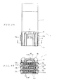
- Figs. 3A and 3B show the wire harness of Fig. 1, with Fig. 3A being a plan view, and Fig. 3B being a front view;
- Fig. 4 is a sectional view along line 4-4 in Fig. 3A;
- Fig. 5 is a sectional view along line 5-5 in Fig. 3B;
- Fig. 6 is a schematic plan view of a flexible circuit board (hereafter simply referred to as "FPC");
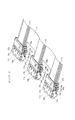
- Fig. 7 is a perspective view for illustrating a step of accommodating a plurality of contacts connected to the FPC in the contact accommodating cavities of upper-stage, middle-stage, and lower-stage base housings;
- Fig. 8 is a perspective view for illustrating a step of pivoting about hinge parts strain relief members respectively provided on the upper-stage, middle-stage, and lower-stage base housings;
- Fig. 9 is a perspective view in a state in which the strain relief members are pivoted about the hinge parts;
- Fig. 10 is a perspective view for illustrating a step of attaching a lock housing to the upper-stage base housing that is located at the very top of the stacked upper-stage, middle-stage, and lower-stage base housings;
- Fig. 11 is a perspective view for illustrating a step of attaching a lock housing to the upper-stage base housing that is located at the very top of the stacked upper-stage, middle-stage, and lower-stage base housings;
- Fig. 12 is a perspective view of the upper-stage, middle-stage, and lower-stage base housings constituting a conventional example of a connector; and
- Figs. 13A to 13C are further explanatory diagrams of a conventional example of a connector assembly.
- In Figs. 7 through 10, the lower-stage base housing is shown at the top, and the upper-stage base housing is shown at the bottom.
- In Figs. 1 through 5, the
wire harness 1 is formed by connecting anelectrical connector 10 to one end of anFPC 2. As is shown in Fig. 6, for example, theFPC 2 to which theelectrical connector 10 is connected, an FPC is used which has a plurality ofconductor patterns 2a on one surface thereof, and which comprises three firstconnector connecting parts 3 on one end, five secondconnector connecting parts 4 on the other end, and one firstconnector connecting part 3 and two secondconnector connecting parts 4 substantially in the central portion. - The
electrical connector 10 comprises mutually stackable upper-stage, middle-stage, and lower-stage base housings lock housing 40. Although theelectrical connector 10 is not limited to a connector comprising upper-stage, middle-stage, and lower-stage base housings - As is shown most clearly in Fig. 7, the upper-
stage base housing 11a comprises a substantially rectangular housingmain body 12a that has a plurality ofcontact accommodating holes 14a in a single row, and abottom plate part 13a that extends rearward (rightward in Fig. 7) from the housingmain body 12a. The upper-stage base housing 11a is formed by molding an insulating resin. A plurality of pairs ofside wall parts 15a that extend rearward from the rear surface of the housingmain body 12a in positions corresponding to both sides of thecontact accommodating holes 14a are formed on thebottom plate part 13a, and contactaccommodating cavities 16a are defined by thecontact accommodating holes 14a and the spaces between the pairs ofside wall parts 15a. Thus, the plurality ofcontact accommodating cavities 16a in a single row are formed in the upper-stage base housing 11a. Furthermore, astrain relief member 17a is integrally provided via ahinge part 27a (see Fig. 9) on the undersurface (upper surface in Fig. 7) of the housingmain body 12a of the upper-stage base housing 11 a. Astrain relief projection 18a is formed so as to protrude substantially from the central portion in the direction of width of thisstrain relief member 17a, and ahole part 26a into which thestrain relief projection 18a is inserted is formed in thebottom plate part 13a. Moreover, a pair of lockingprojections 19a are provided on either side surface of thestrain relief member 17a in the direction of width, and a pair of locking parts having lockingholes 25a with which thelocking projections 19a are locked are provided in an upright attitude on thebottom plate part 13a. In addition, a plurality of protrudingparts 28a (see Fig. 11) are provided on the upper surface of the housingmain body 12a, and a pair of lockingprojections 24a that protrude upward are also provided on either side of the housingmain body 12a. Furthermore, a pair of lockingprojections 24a that protrude upward are provided on either side of thebottom plate part 13a as well. These lockingprojections recesses lock housing 40, and the protrudingparts 28a are fitted intogrooves 45 formed in thelock housing 40, so that these parts have the function of preventing excessive looseness of thelock housing 40. Moreover, a plurality ofgrooves 20a are formed in the undersurface of the housingmain body 12a, and a pair of lockingrecesses 21a are formed at either side of the housingmain body 12a beneath the lockingprojections 24a. In addition, a pair of lockingrecesses 22a are also formed in either side of thestrain relief member 17a. - Furthermore, the middle-
stage base housing 11b has the same shape as the upper-stage base housing 11a, and comprises a substantially rectangular housingmain body 12b that has a plurality ofcontact accommodating holes 14b in a single row, and abottom plate part 13b that extends rearward from the housingmain body 12b as shown most clearly in Fig. 7; the middle-stage base housing 11b is formed by molding an insulating resin. A plurality of pairs ofside wall parts 15b that extend rearward from the rear surface of the housingmain body 12b in positions corresponding to both sides of thecontact accommodating holes 14b are formed on thebottom plate part 13b, and contactaccommodating cavities 16b are demarcated by thecontact accommodating holes 14b and the spaces between the pairs ofside wall parts 15b. Thus, the plurality ofcontact accommodating cavities 16b in a single row are formed in the middle-stage base housing 11b. Furthermore, astrain relief member 17b is integrally provided via ahinge part 27b (see Fig. 9) on the undersurface (upper surface in Fig. 7) of the housingmain body 12b of the middle-stage base housing 11b. Astrain relief projection 18b is formed so as to protrude substantially from the central portion in the direction of width of thisstrain relief member 17b, and ahole part 26b into which thestrain relief projection 18b is inserted is formed in thebottom plate part 13b. Moreover, a pair of lockingprojections 19b are provided on either side surface of thestrain relief member 17b in the direction of width, and a pair of locking parts having lockingholes 25b with which the lockingprojections 19b are locked are installed in an upright attitude on thebottom plate part 13b. In addition, a plurality of protruding parts (not shown in the figures) are provided on the upper surface of the housingmain body 12b, and a pair of lockingprojections 24b that protrude upward are also provided on either side of the housingmain body 12b. Furthermore, a pair of lockingprojections 24b that protrude upward are provided on either side of thebottom plate part 13b as well. These lockingprojections stage base housing 11a, and the protruding parts are fitted into thegrooves 20a formed in the upper-stage base housing 11a. Moreover, a plurality ofgrooves 20b are formed in the undersurface of the housingmain body 12b, and a pair of lockingrecesses 21b are formed at either side of the housingmain body 12b beneath the lockingprojections 24b. In addition, a pair of lockingrecesses 22b are also formed in either side of thestrain relief member 17b. - Furthermore, the lower-
stage base housing 11 c has the same shape as the upper-stage base housing 11a and middle-stage base housing 11b, and comprises a substantially rectangular housingmain body 12c that has a plurality ofcontact accommodating holes 14c in a single row, and abottom plate part 13c that extends rearward from the housingmain body 12c as shown most clearly in Fig. 7; the lower-stage base housing 11c is formed by molding an insulating resin. A plurality of pairs ofside wall parts 15c that extend rearward from the rear surface of the housingmain body 12c in positions corresponding to both sides of thecontact accommodating holes 14c are formed on thebottom plate part 13c, and contactaccommodating cavities 16c are demarcated by thecontact accommodating holes 14c and the spaces between the pairs ofside wall parts 15c. Thus, the plurality ofcontact accommodating cavities 16c in a single row are formed in the lower-stage base housing 11c. Furthermore, astrain relief member 17c is integrally provided via ahinge part 27c (see Fig. 9) on the undersurface (upper surface in Fig. 7) of the housingmain body 12c of the lower-stage base housing 11c. Astrain relief projection 18c is formed so as to protrude substantially from the central portion in the direction of width of thisstrain relief member 17c, and ahole part 26c into which thestrain relief projection 18c is inserted is formed in thebottom plate part 13c. Moreover, a pair of lockingprojections 19c are provided on either side surface of thestrain relief member 17c in the direction of width, and a pair of locking parts having lockingholes 25c with which the lockingprojections 19c are locked are installed in an upright attitude on thebottom plate part 13c. In addition, a plurality of protruding parts (not shown in the figures) are provided on the upper surface of the housingmain body 12c, and a pair of lockingprojections 24c that protrude upward are also provided on either side of the housingmain body 12c. Furthermore, a pair of lockingprojections 24c that protrude upward are provided on either side of thebottom plate part 13c as well. These lockingprojections stage base housing 11b, and the protruding parts are fitted into thegrooves 20b formed in the middle-stage base housing 11b. Moreover, a plurality ofgrooves 20c are formed in the undersurface of the housingmain body 12c, and a pair of lockingrecesses 21c are formed at either side of the housingmain body 12c beneath the lockingprojections 24c. In addition, a pair of lockingrecesses 22c are also formed in either side of thestrain relief member 17c. Thus, the lower-stage base housing 11c is constructed so that another base housing having the same shape as the upper-stage, middle-stage, and lower-stage base housings stage base housing 11c. Furthermore, a pair ofprojections stage base housings - The
lock housing 40 is to be attached to the surface of the upper-stage base housing 11a that is located in the uppermost position of the stacked upper-stage, middle-stage, and lower-stage base housings lock housing 40 comprises a substantially rectangular lock housingmain body 41, acantilever locking arm 42 that is provided substantially in the central portion of the lock housingmain body 41 in the direction of width, and a lockingprojection 43 that is provided on the upper surface of the lockingarm 42. Thelock housing 40 is formed by molding an insulating resin. The lockingprojection 43 of the lockingarm 42 engages with the locking part of a mating connector (not shown in the figures), thus having the function of preventing theelectrical connector 10 from coming out of the mating connector. Furthermore, the locking recesses 44, 44 with which thelocking projections stage base housing 11a respectively engage are formed in either side of the lock housingmain body 41. In addition, a plurality ofgrooves 45 into which the protrudingparts 28a, provided on the upper-stage base housing 11a are fitted, are formed in the undersurface of the lock housingmain body 41. - As is shown in Fig. 7, a plurality of upper-
stage contacts 30a are connected to the firstconnector connecting part 3 that is located on the rightmost side (left side in Fig. 7) of the three firstconnector connecting parts 3 provided on one end of theFPC 2, a plurality of middle-stage contacts 30b are connected to the firstconnector connecting part 3 located in the middle, and a plurality of lower-stage contacts 30c are connected to the firstconnector connecting part 3 located on the leftmost side. Among these connected contacts, the upper-stage contacts 30a are designed to be accommodated inside thecontact accommodating cavities 16a in the upper-stage base housing 11a, the middle-stage contacts 30b are designed to be accommodated inside thecontact accommodating cavities 16b in the middle-stage base housing 11b, and the lower-stage contacts 30c are designed to be accommodated inside thecontact accommodating cavities 16c in the lower-stage base housing 11c. The "electrical connector" stipulated inclaim 1 is constructed from the upper-stage, middle-stage, and lower-stage base housings housing 40, and upper-stage, middle-stage, and lower-stage contacts stage contacts receptacle part part receptacle part part receptacle part accommodating hole - Next, a method for arranging wire harness will be described in reference to Figs. 7 through 11.
- For example, if a description is given in a case where the wire harness I is connected to a controller for an automotive transmission, first, as is shown in Fig. 7, the plurality of upper-
stage contacts 30a are connected by piercing to the firstconnector connecting part 3 that is located on the rightmost side (left side in Fig. 7) of the three firstconnector connecting parts 3 provided on one end of theFPC 2. The plurality of middle-stage contacts 30b are connected by piercing to the firstconnector connecting part 3 located in the middle, and the plurality of lower-stage contacts 30c are connected by piercing to the firstconnector connecting part 3 located on the leftmost side. - Next, the plurality of upper-
stage contacts 30a connected to theFPC 2 are accommodated in thecontact accommodating cavities 16a in a single row in the upper-stage base housing 11a, the plurality of middle-stage contacts 30b are accommodated in thecontact accommodating cavities 16b in a single row in the middle-stage base housing 11b, and the plurality of lower-stage contacts 30c are accommodated in thecontact accommodating cavities 16c in a single row in the lower-stage base housing 11c. As a result, the arrangement shown in Fig. 8 is obtained. - Then, the
strain relief member 17a provided on the upper-stage base housing 11a is caused to pivot about thehinge part 27a, so that thestrain relief projection 18a is engaged with thehole part 26a via anopening 5 formed in theFPC 2. At this point, the lockingprojections 19a are locked with the lockingholes 25a, so that thestrain relief member 17a is locked. As a result, in cases where an external force is applied to theFPC 2, it is possible to relieve the stress generated in the firstconnector connecting part 3 of theFPC 2 to which the upper-stage contacts 30a are connected. Furthermore, thestrain relief member 17b provided on the middle-stage base housing 11b is similarly caused to pivot about thehinge part 27b, so that thestrain relief projection 18b is engaged with thehole part 26b via anopening 5 formed in theFPC 2, and the lockingprojections 19b are locked with the lockingholes 25b, thus locking thestrain relief member 17b. As a result, in cases where an external force is applied to theFPC 2, it is possible to relieve the stress generated in the firstconnector connecting part 3 of theFPC 2 to which the middle-stage contacts 30b are connected. Moreover, thestrain relief member 17c provided on the lower-stage base housing 11c is similarly caused to pivot about thehinge part 27c, so that thestrain relief projection 18c is engaged with thehole part 26c via anopening 5 formed in theFPC 2, and the lockingprojections 19c are locked with the lockingholes 25c, thus locking thestrain relief member 17c. As a result, in cases where an external force is applied to theFPC 2, it is possible to relieve the stress generated in the firstconnector connecting part 3 of theFPC 2 to which the lower-stage contacts 30c are connected. Consequently, in cases where vibration occurs, the stress generated in the firstconnector connecting parts 3 of theFPC 2 can be relieved by thestrain relief members - Next, the respective upper-stage, middle-stage, and lower-
stage base housings - Subsequently, by folding the
FPC 2, the middle-stage base housing 11b is stacked on top of the lower-stage base housing 11c, and the upper-stage base housing 11a is stacked on top of the middle-stage base housing 11b as shown in Figs. 10 and 11. In this case, the lockingprojections stage base housing 11 c engage with the locking recesses 21b, 22b of the uaiddle-stage base housing 11b, so that the lower-stage base housing 11c and middle-stage base housing 11b are locked together. Furthermore, the lockingprojections stage base housing 11b engage with the locking recesses 21a, 22a of the upper-stage base housing 11a, so that the middle-stage base housing 11b and upper-stage base housing 11a are locked together. Moreover, the protruding parts of the lower-stage base housing 11c are fitted into thegrooves 20b in the middle-stage base housing 11b, thus preventing excessive looseness between the lower-stage base housing 11c and middle-stage base housing 11b, and the protruding parts of the middle-stage base housing 11b are fitted into thegrooves 20a in the upper-stage base housing 11a, thus preventing excessive looseness between the middle-stage base housing 11b and upper-stage base housing 11a. - Finally, the
lock housing 40 is attached to the surface of the upper-stage base housing 11a located in the uppermost position of the stacked upper-stage, middle-stage, and lower-stage base housings projections stage base housing 11a engage with the locking recesses 44, 44 in thelock housing 40, so that thelock housing 40 is locked with the upper-stage base housing 11a. Furthermore, the protrudingparts 28a of the upper-stage base housing 11a are fitted into thegrooves 45 in thelock housing 40, thus preventing excessive looseness of thelock housing 40. As a result, arrangement of thewire harness 1 is completed. - In this method for arranging a
wire harness 1, after the plurality ofcontacts FPC 2, the plurality ofcontacts contact accommodating cavities stage base housings stage base housings stage base housings wire harness 1. Accordingly, the opening bored in the transmission case can be made small. Furthermore, there is no need to cut thin parts that are provided in order to form a plurality of base housings as one linked body in a single molding process as in the past, so that the work for arranging wire harness is facilitated and simplified. Moreover, since the upper-stage, middle-stage, and lower-stage base housings - In addition, the plurality of
contacts FPC 2 are respectively accommodated in thecontact accommodating cavities stage base housings - An embodiment of the present invention has been described above. However, the present invention is not limited to this embodiment, and various alterations and modifications can be made.
- For example, it is sufficient if the
electrical connector 10 is a connector that is connected to a flat cable such as a flexible flat cable (FFC) other than an FPC. - Furthermore the
electrical connector 10 may be connected to both ends or only to one end of an FPC 2 (flat cable), or may also be connected to a connecting part that is branched out from an intermediate portion of theFPC 2. - Moreover, as long as the
electrical connector 10 comprises a plurality of mutually stackable base housings, the electrical connector is not limited to a connector comprising upper-stage, middle-stage, and lower-stage base housings - In addition, in the embodiment described above, a
lock housing 40 is attached only to the upper surface of upper-stage base housing 11a. However, it would also be possible to attach twolock housings 40 to both the upper-stage and lower-stage base housings lock housing 40 only to the undersurface of the lower-stage base housing 11c. In other words, it is sufficient if at least one lock housing is attached to the uppermost and/or lowermost base housing of the plurality of stacked base housings. - Furthermore, the use of the
wire harness 1 is not limited to a case in which thiswire harness 1 is used for connection to a controller for an automotive transmission; this wire harness may also be used in another electrical circuitry. Moreover, when arrangingwire harness 1, the respective upper-stage, middle-stage, and lower-stage base housings
Claims (6)
- An electrical connector (10) for connection to a flat cable (2), comprising:a plurality of mutually stackable base housings (11a, 11b, 11c) having the same shape, with each of the base housings having contact accommodating cavities (16a, 16b, 16c) in a single row;at least one lock housing (40) that is attached to at least one of the uppermost base housing (11a) and the lowermost base housing (11c) of the plurality of stacked base housings (11a, 11b, 11c); anda plurality of contacts (30a, 30b, 30c) that are connected to the flat cable (2) and that are accommodated in the contact accommodating cavities (16a, 16b, 16c) in the plurality of base housings (11a, 11b, 11c).
- The electrical connector (10) according to claim 1, wherein a strain relief member (18a, 18b, 18c) is provided in an integral manner on each of the plurality of base housings via a hinge part (27a, 27b, 27c) for relieving stress generated in the flat cable (2) when an external force is applied to the flat cable (2).
- A wire harness (1) in which an electrical connector (10) is connected to a flat cable (2), wherein the electrical connector (10) comprises: a plurality of mutually stackable base housings (11a, 11b, 11c) having the same shape, with each of the base housings (11a, 11b, 11c) having contact accommodating cavities (16a, 16b, 16c) in a single row; at least one lock housing (40) that is attached to at least one of the uppermost base housing (11a) and the lowermost base housing (11c) of the plurality of stacked base housings (11a, 11b, 11c); and a plurality of contacts (30a, 30b, 30c) that are connected to the flat cable (2) and that are accommodated in the contact accommodating cavities (16a, 16b, 16c) in the plurality of base housings (11a, 11b, 11c).
- The wire harness (1) according to claim 3, wherein a strain relief member (18a, 18b, 18c) is provided in an integral manner on each of the plurality of base housings (11a, 11b, 11c) via a hinge part (27a, 27b, 27c) that relieves the stress generated in the flat cable (2) when an external force is applied to the flat cable.
- A method for arranging a wire harness (1) comprising the steps of:connecting a plurality of contacts (30a, 30b, 30c) to a flat cable (2);accommodating the plurality of contacts (30a, 30b, 30c) in contact accommodating cavities (16a, 16b, 16c) in a single row in a plurality of base housings (11a, 11b, 11c);passing each of the plurality of base housings (11a, 11b, 11c) successively through an opening in a housing;stacking the plurality of base housings (11a, 11b, 11c); andattaching at least one lock housing (40) to at least one of the uppermost base housing (11a) and the lowermost base housing (11c) of the plurality of stacked base housings.
- The method for arranging wire harness (1) according to claim 5, wherein following the accommodation of the plurality of contacts (30a, 30b, 30c) in the contact accommodating cavities (16a, 16b, 16c) in the plurality of base housings (11a, 11b, 11c), a strain relief member (18a, 18b, 18c), that is provided in an integral manner on each of the plurality of base housings (11a, 11b, 11c) via a hinge part (27a, 27b, 27c) and that relieves the stress generated in the flat cable (2), is caused to pivot about the hinge part (27a, 27b, 27c).
Applications Claiming Priority (1)
| Application Number | Priority Date | Filing Date | Title |
|---|---|---|---|
| JP2005112601A JP2006294386A (en) | 2005-04-08 | 2005-04-08 | Electric connector, wire harness and method for wire harness arrangement |
Publications (2)
| Publication Number | Publication Date |
|---|---|
| EP1710864A2 true EP1710864A2 (en) | 2006-10-11 |
| EP1710864A3 EP1710864A3 (en) | 2008-03-26 |
Family
ID=36644875
Family Applications (1)
| Application Number | Title | Priority Date | Filing Date |
|---|---|---|---|
| EP06111986A Pending EP1710864A3 (en) | 2005-04-08 | 2006-03-30 | Electrical connector, wire harness and method for arranging wire harness |
Country Status (4)
| Country | Link |
|---|---|
| US (1) | US7186151B2 (en) |
| EP (1) | EP1710864A3 (en) |
| JP (1) | JP2006294386A (en) |
| CN (1) | CN1845381A (en) |
Cited By (3)
| Publication number | Priority date | Publication date | Assignee | Title |
|---|---|---|---|---|
| EP1968162A3 (en) * | 2007-03-07 | 2009-12-30 | Yamaichi Electronics Deutschland GmbH | Harness and method for mounting a harness |
| US20240332848A1 (en) * | 2023-03-27 | 2024-10-03 | Tyco Electronics (Suzhou) Ltd. | Electrical Connector Housing and Electrical Connector |
| EP4692878A1 (en) | 2024-08-09 | 2026-02-11 | ODU GmbH & Co KG. | Modular connector housing |
Families Citing this family (30)
| Publication number | Priority date | Publication date | Assignee | Title |
|---|---|---|---|---|
| US8225498B2 (en) * | 2007-04-26 | 2012-07-24 | Siemens Industry, Inc. | System and method for reconfiguring a harness board |
| CN102148431B (en) * | 2010-02-04 | 2013-11-06 | 鸿富锦精密工业(深圳)有限公司 | Connector |
| JP5547525B2 (en) * | 2010-03-17 | 2014-07-16 | 矢崎総業株式会社 | Terminal connector |
| TWI425718B (en) * | 2011-06-21 | 2014-02-01 | 財團法人國家實驗研究院國家晶片系統設計中心 | Connector structure group and its connector structure |
| US9601880B2 (en) | 2011-11-08 | 2017-03-21 | Ortronics, Inc. | Cable assemblies and associated systems and methods |
| US20130115806A1 (en) * | 2011-11-08 | 2013-05-09 | Ortronics, Inc. | Patch Cord Assemblies, Methods and Systems |
| JP2013137922A (en) * | 2011-12-28 | 2013-07-11 | Tyco Electronics Japan Kk | Electric connector |
| CN202600189U (en) * | 2012-05-31 | 2012-12-12 | 泰科电子(上海)有限公司 | Adapter assembly and connector assembly |
| US8845366B2 (en) * | 2012-12-17 | 2014-09-30 | Derrick Lewis Brown | Apparatus, system and method for composite and symmetrical hybrid electronic connectors |
| US10322868B2 (en) | 2013-03-15 | 2019-06-18 | Ortronics, Inc. | Cable assembly dispenser systems and associated methods |
| JP6079399B2 (en) * | 2013-04-16 | 2017-02-15 | 住友電装株式会社 | Wire harness and connector member |
| US9166316B2 (en) * | 2013-11-05 | 2015-10-20 | Super Micro Computer Inc. | Data storage connecting device |
| JP6268602B2 (en) * | 2014-09-05 | 2018-01-31 | 株式会社オートネットワーク技術研究所 | connector |
| JP5926347B2 (en) * | 2014-09-26 | 2016-05-25 | ファナック株式会社 | Connector connection structure |
| KR102244266B1 (en) * | 2017-02-21 | 2021-04-26 | 현대자동차주식회사 | Connector device |
| JP6669996B2 (en) * | 2018-01-22 | 2020-03-18 | 株式会社オートネットワーク技術研究所 | connector |
| DE102018207794A1 (en) * | 2018-05-17 | 2019-11-21 | Te Connectivity Germany Gmbh | Ribbon cable connector, connector assembly and use of a connector |
| WO2020138191A1 (en) * | 2018-12-28 | 2020-07-02 | 株式会社オートネットワーク技術研究所 | Substrate connector, and device |
| JP7094641B2 (en) * | 2019-10-16 | 2022-07-04 | 矢崎総業株式会社 | connector |
| WO2021079587A1 (en) * | 2019-10-24 | 2021-04-29 | 株式会社オートネットワーク技術研究所 | Joint connector |
| JP7359080B2 (en) * | 2020-06-08 | 2023-10-11 | 株式会社オートネットワーク技術研究所 | connector unit |
| CN116171511B (en) * | 2020-08-26 | 2026-04-03 | 住友电装株式会社 | Molded connectors |
| JP7427167B2 (en) * | 2020-11-02 | 2024-02-05 | 株式会社オートネットワーク技術研究所 | connector |
| EP4318824A4 (en) * | 2021-03-23 | 2025-03-12 | Furukawa Electric Co., Ltd. | JUNCTION CONNECTOR, ELECTRICAL WIRE EQUIPPED WITH CONNECTOR AND CONNECTOR HOUSING |
| JP7779801B2 (en) * | 2022-05-20 | 2025-12-03 | 矢崎総業株式会社 | Flat Cable Connectors |
| KR102664641B1 (en) * | 2022-07-26 | 2024-05-10 | 주식회사 경신 | Ring terminal device for wiring grounding |
| JP7882763B2 (en) * | 2022-11-28 | 2026-06-30 | 矢崎総業株式会社 | Coupler device |
| JP2024078683A (en) * | 2022-11-30 | 2024-06-11 | 日本航空電子工業株式会社 | Connector assembly and connection method |
| JP7898394B2 (en) * | 2023-01-18 | 2026-07-31 | 日本航空電子工業株式会社 | Connector assemblies and structures |
| JP7587619B2 (en) * | 2023-03-08 | 2024-11-20 | 矢崎総業株式会社 | Wire harness manufacturing method and wire harness |
Citations (1)
| Publication number | Priority date | Publication date | Assignee | Title |
|---|---|---|---|---|
| JPH1074541A (en) | 1996-08-30 | 1998-03-17 | Yazaki Corp | Housing for crimping connector and method of assembling it |
Family Cites Families (13)
| Publication number | Priority date | Publication date | Assignee | Title |
|---|---|---|---|---|
| JPS5650695Y2 (en) * | 1976-06-22 | 1981-11-27 | ||
| JPS61202884U (en) * | 1985-06-11 | 1986-12-19 | ||
| JPH04129181A (en) * | 1990-09-19 | 1992-04-30 | Amp Japan Ltd | Connector module assembly body |
| JPH04233176A (en) * | 1990-12-28 | 1992-08-21 | Amp Japan Ltd | Plug connector |
| JP2518968Y2 (en) * | 1992-02-06 | 1996-12-04 | 矢崎総業株式会社 | Combined connector |
| JP4205240B2 (en) * | 1999-03-01 | 2009-01-07 | 矢崎総業株式会社 | Splice absorption structure |
| JP3701517B2 (en) * | 1999-08-06 | 2005-09-28 | 矢崎総業株式会社 | Pressure welding connector and union connector |
| JP2001210409A (en) * | 2000-01-28 | 2001-08-03 | Yazaki Corp | Connector for flat circuit body and connection structure of flat circuit body to connector |
| EP1178573A3 (en) * | 2000-07-31 | 2003-02-05 | TALLER Automotive GmbH | Connector for flexible printed circuit |
| JP3759869B2 (en) * | 2000-10-27 | 2006-03-29 | 住友電装株式会社 | Connector device |
| JP3879057B2 (en) * | 2001-03-30 | 2007-02-07 | 住友電装株式会社 | Joint connector |
| JP2002367714A (en) * | 2001-06-04 | 2002-12-20 | Yazaki Corp | Wire harness and method of manufacturing wire harness |
| JP3984560B2 (en) * | 2003-05-06 | 2007-10-03 | 株式会社オートネットワーク技術研究所 | Multilayer connector housing |
-
2005
- 2005-04-08 JP JP2005112601A patent/JP2006294386A/en active Pending
-
2006
- 2006-03-30 EP EP06111986A patent/EP1710864A3/en active Pending
- 2006-03-31 CN CN200610073356.3A patent/CN1845381A/en active Pending
- 2006-04-07 US US11/279,081 patent/US7186151B2/en not_active Expired - Fee Related
Patent Citations (1)
| Publication number | Priority date | Publication date | Assignee | Title |
|---|---|---|---|---|
| JPH1074541A (en) | 1996-08-30 | 1998-03-17 | Yazaki Corp | Housing for crimping connector and method of assembling it |
Cited By (5)
| Publication number | Priority date | Publication date | Assignee | Title |
|---|---|---|---|---|
| EP1968162A3 (en) * | 2007-03-07 | 2009-12-30 | Yamaichi Electronics Deutschland GmbH | Harness and method for mounting a harness |
| US20240332848A1 (en) * | 2023-03-27 | 2024-10-03 | Tyco Electronics (Suzhou) Ltd. | Electrical Connector Housing and Electrical Connector |
| EP4692878A1 (en) | 2024-08-09 | 2026-02-11 | ODU GmbH & Co KG. | Modular connector housing |
| EP4692876A1 (en) | 2024-08-09 | 2026-02-11 | ODU GmbH & Co KG. | Modular connector housing |
| JP2026031473A (en) * | 2024-08-09 | 2026-02-24 | オーデーウー ゲーエムベーハー ウント コー カーゲー | Modular Connector Housing |
Also Published As
| Publication number | Publication date |
|---|---|
| CN1845381A (en) | 2006-10-11 |
| EP1710864A3 (en) | 2008-03-26 |
| US20060228932A1 (en) | 2006-10-12 |
| US7186151B2 (en) | 2007-03-06 |
| JP2006294386A (en) | 2006-10-26 |
Similar Documents
| Publication | Publication Date | Title |
|---|---|---|
| US7186151B2 (en) | Electrical connector, wire harness, and method for arranging wire harness | |
| US5057026A (en) | Electric junction box | |
| US5229922A (en) | Electrical junction box with stacked insulating plates and bus-bars with stepped tabs | |
| US7927111B2 (en) | Electrical junction box | |
| JP5812429B2 (en) | Electrical junction box | |
| US7364449B2 (en) | Joint connector block | |
| EP0734097B1 (en) | A circuit member and an electrical connection box | |
| JP5696691B2 (en) | Electrical junction box | |
| CN101494336A (en) | Cable connector assembly | |
| CA2299855C (en) | Splice absorbing structure | |
| US6220876B1 (en) | Electrical interconnect system and method for integrating a bussed electrical distribution center with a printed circuit board | |
| JP5648981B2 (en) | Electrical junction box | |
| EP1248322A2 (en) | Mounting structure of connector for use with curcuit board | |
| EP1669247B1 (en) | Electric connection box | |
| KR20050085717A (en) | Flexible cable electrical connector | |
| EP1174311A1 (en) | Junction box | |
| JP7655777B2 (en) | Terminals, wire connectors and wire-to-board connectors | |
| JP3879750B2 (en) | Electrical junction box | |
| US6722905B2 (en) | Board connector | |
| KR20080076901A (en) | Electrical connector | |
| EP1713147B1 (en) | An electrical connector | |
| EP1577977B1 (en) | Electrical junction box | |
| EP1718140A2 (en) | Electric connection box | |
| JP2002305063A (en) | Conductor wiring structure and joint connector using the structure | |
| JP2006060970A (en) | Electric connection box |
Legal Events
| Date | Code | Title | Description |
|---|---|---|---|
| PUAI | Public reference made under article 153(3) epc to a published international application that has entered the european phase |
Free format text: ORIGINAL CODE: 0009012 |
|
| AK | Designated contracting states |
Kind code of ref document: A2 Designated state(s): AT BE BG CH CY CZ DE DK EE ES FI FR GB GR HU IE IS IT LI LT LU LV MC NL PL PT RO SE SI SK TR |
|
| AX | Request for extension of the european patent |
Extension state: AL BA HR MK YU |
|
| PUAL | Search report despatched |
Free format text: ORIGINAL CODE: 0009013 |
|
| AK | Designated contracting states |
Kind code of ref document: A3 Designated state(s): AT BE BG CH CY CZ DE DK EE ES FI FR GB GR HU IE IS IT LI LT LU LV MC NL PL PT RO SE SI SK TR |
|
| AX | Request for extension of the european patent |
Extension state: AL BA HR MK YU |
|
| RIC1 | Information provided on ipc code assigned before grant |
Ipc: H01R 13/58 20060101ALI20080221BHEP Ipc: H01R 12/08 20060101ALI20080221BHEP Ipc: H01R 13/514 20060101AFI20080221BHEP |
|
| 17P | Request for examination filed |
Effective date: 20080902 |
|
| AKX | Designation fees paid |
Designated state(s): DE ES FR |
|
| 17Q | First examination report despatched |
Effective date: 20081125 |
|
| STAA | Information on the status of an ep patent application or granted ep patent |
Free format text: STATUS: THE APPLICATION IS DEEMED TO BE WITHDRAWN |