EP1710508A1 - Steam cooking apparatus - Google Patents
Steam cooking apparatus Download PDFInfo
- Publication number
- EP1710508A1 EP1710508A1 EP04821013A EP04821013A EP1710508A1 EP 1710508 A1 EP1710508 A1 EP 1710508A1 EP 04821013 A EP04821013 A EP 04821013A EP 04821013 A EP04821013 A EP 04821013A EP 1710508 A1 EP1710508 A1 EP 1710508A1
- Authority
- EP
- European Patent Office
- Prior art keywords
- steam
- food
- heating chamber
- sub
- cavity
- Prior art date
- Legal status (The legal status is an assumption and is not a legal conclusion. Google has not performed a legal analysis and makes no representation as to the accuracy of the status listed.)
- Withdrawn
Links
- 238000010411 cooking Methods 0.000 title claims description 54
- 238000010438 heat treatment Methods 0.000 claims abstract description 112
- 235000013305 food Nutrition 0.000 claims abstract description 97
- 238000007667 floating Methods 0.000 claims abstract description 5
- XLYOFNOQVPJJNP-UHFFFAOYSA-N water Substances O XLYOFNOQVPJJNP-UHFFFAOYSA-N 0.000 description 63
- 238000010276 construction Methods 0.000 description 18
- 238000007664 blowing Methods 0.000 description 17
- 238000010586 diagram Methods 0.000 description 5
- 229910001220 stainless steel Inorganic materials 0.000 description 5
- 230000005494 condensation Effects 0.000 description 4
- 238000009833 condensation Methods 0.000 description 4
- 229910052751 metal Inorganic materials 0.000 description 4
- 239000002184 metal Substances 0.000 description 4
- 229920006395 saturated elastomer Polymers 0.000 description 4
- 239000010935 stainless steel Substances 0.000 description 4
- RYGMFSIKBFXOCR-UHFFFAOYSA-N Copper Chemical compound [Cu] RYGMFSIKBFXOCR-UHFFFAOYSA-N 0.000 description 2
- 241001311547 Patina Species 0.000 description 2
- 229910052802 copper Inorganic materials 0.000 description 2
- 239000010949 copper Substances 0.000 description 2
- 230000002708 enhancing effect Effects 0.000 description 2
- 238000000034 method Methods 0.000 description 2
- 230000002093 peripheral effect Effects 0.000 description 2
- 241000195493 Cryptophyta Species 0.000 description 1
- 229910045601 alloy Chemical group 0.000 description 1
- 239000000956 alloy Chemical group 0.000 description 1
- 229910052782 aluminium Inorganic materials 0.000 description 1
- XAGFODPZIPBFFR-UHFFFAOYSA-N aluminium Chemical compound [Al] XAGFODPZIPBFFR-UHFFFAOYSA-N 0.000 description 1
- 244000052616 bacterial pathogen Species 0.000 description 1
- 238000005452 bending Methods 0.000 description 1
- 235000013361 beverage Nutrition 0.000 description 1
- 230000015572 biosynthetic process Effects 0.000 description 1
- 239000000919 ceramic Substances 0.000 description 1
- 238000005034 decoration Methods 0.000 description 1
- 230000008014 freezing Effects 0.000 description 1
- 238000007710 freezing Methods 0.000 description 1
- 239000011521 glass Substances 0.000 description 1
- 239000011810 insulating material Substances 0.000 description 1
- 238000009413 insulation Methods 0.000 description 1
- JEIPFZHSYJVQDO-UHFFFAOYSA-N iron(III) oxide Inorganic materials O=[Fe]O[Fe]=O JEIPFZHSYJVQDO-UHFFFAOYSA-N 0.000 description 1
- 235000013372 meat Nutrition 0.000 description 1
- 239000007769 metal material Substances 0.000 description 1
- 150000002739 metals Chemical class 0.000 description 1
- 238000012986 modification Methods 0.000 description 1
- 230000004048 modification Effects 0.000 description 1
- 238000000465 moulding Methods 0.000 description 1
- 238000010422 painting Methods 0.000 description 1
- 230000000284 resting effect Effects 0.000 description 1
- 230000000630 rising effect Effects 0.000 description 1
- 238000004381 surface treatment Methods 0.000 description 1
- 238000011144 upstream manufacturing Methods 0.000 description 1
Images





Classifications
-
- F—MECHANICAL ENGINEERING; LIGHTING; HEATING; WEAPONS; BLASTING
- F24—HEATING; RANGES; VENTILATING
- F24C—DOMESTIC STOVES OR RANGES ; DETAILS OF DOMESTIC STOVES OR RANGES, OF GENERAL APPLICATION
- F24C15/00—Details
- F24C15/32—Arrangements of ducts for hot gases, e.g. in or around baking ovens
- F24C15/322—Arrangements of ducts for hot gases, e.g. in or around baking ovens with forced circulation
- F24C15/327—Arrangements of ducts for hot gases, e.g. in or around baking ovens with forced circulation with air moisturising
Definitions
- the present invention relates to a steam cooking apparatus.
- Patent Document 1 discloses a steam cooking apparatus wherein steam is jetted into food trays.
- Patent Document 2 discloses a cooking apparatus wherein overheated steam is blown into an oven chamber, or steam inside the oven chamber is turned into overheated steam by being radiation-heated.
- Patent Document 3 discloses a cooking apparatus wherein overheated steam is supplied to inside an entire heating chamber, or to around food, or to both.
- Patent Document 1 The steam cooking apparatus disclosed in Patent Document 1 is for business use.
- steam is supplied through a steam supply pipe to a plurality of food trays.
- the steam supply pipe running naked inside the food trays, however, this construction is visually unrefined, making the apparatus unsuitable for household use.
- the range over which steam is jetted is restricted by the shape of the steam supply tube, making it difficult to blow steam evenly onto articles-to-be-heated (food) placed inside individual heating chambers.
- Patent Document 2 The cooking apparatus disclosed in Patent Document 2 is so constructed that food is cooked by, instead of having steam jetted toward it, being enveloped in steam. This design is insufficient to apply a large amount of heat quickly to the food.
- the cooking apparatus disclosed in Patent Document 3 supplies steam through first steam guiding means to around food, from above it.
- overheated steam here permits an upper part of the food to be roasted brown.
- a lower part of the food in contrast, is simply heated by steam that is supplied to inside the entire heating chamber through second steam guiding means, and thus does not receive so much heat as the upper part does.
- the lower part is not roasted brown, nor does it even reach the temperature to which the upper part is heated. That is, different parts of the food is differently heated, causing it to be cooked unevenly.
- a steam cooking apparatus is provided with:
- the apparatus With this construction, steam is jetted out through the upper jet hole provided in the ceiling part of the heating chamber and through the side jet hole provided in the lower part of the side wall of the heating chamber at one or both sides thereof.
- the apparatus has a visually refined construction suitable in a cooking apparatus for household use.
- steam blows onto the food not only from above but also from the side, more specifically from both sides.
- the part of the food that is not hit by the steam from above is as well cooked as the upper part, contributing to an evenly-cooked, neat-looking result.
- the food receives heat from around the entire surface thereof, it is heated to the center sufficiently in a short time.
- the food is supported in a state floating above the floor surface of the heating chamber by supporting means, and, through the side jet hole, steam is blown toward under the food.
- the side jet hole is so positioned and/or directed that the steam jetted out from each side meets under the food.
- the steam jetted out through the side jet hole at each side meets under the food.
- the steam that has reached under the food does not flow straight on, but stagnates and fills under the food. This ensures that steam makes contact with the food.
- the steam there is directed originally in directions tangential to the surface of the food it behaves as if blown in directions normal to the surface of the food. This ensures that the heat of steam is delivered to the food.
- steam generated by the steam generating device is introduced into a sub-cavity provided adjacent to the heating chamber, the steam is then heated inside the sub-cavity by heating means, and the so heated steam is then distributed between the upper jet hole and the side jet hole.
- steam generated by the steam generating device is heated by the heating means in the sub-cavity provided adjacent to the heating chamber.
- steam can be heated to the desired temperature at a place close to the heating chamber. This helps reduce the heat loss that occurs on the way of the supply of steam.
- the steam heated inside the sub-cavity is distributed between the upper and side jet holes. This eliminates the need to provide heating means for each jet hole, and thus helps simplify the construction.
- the steam heated inside the sub-cavity is guided to the side jet hole through a duct formed of a pipe.
- the duct through which the steam heated inside the sub-cavity is guided to the side jet hole is formed of a pipe.
- This duct compared with one formed by bending and joining sheet metal, helps realize the guiding of steam without leakage, and is inexpensive to fabricate.
- the duct withstands an increased interior pressure, making it possible to jet steam out at an increased pressure and hence more strongly.
- the sub-cavity is provided in the ceiling part of the heating chamber.
- the distance from the sub-cavity to the upper jet hole is short. This helps reduce the loss of energy that occurs while the steam heated inside the sub-cavity flows to the upper jet hole.
- the upper jet hole is provided in the floor panel of the sub-cavity.
- the total area of the side jet hole is larger than the total area of the upper jet hole.
- the apparatus has a visually refined construction suitable in a cooking apparatus for household use.
- steam blows onto the food not only from above but also from the side, more specifically from both sides.
- the food is supported in a state floating above the floor surface of the heating chamber by supporting means, and, through the side jet hole, steam is blown toward under the food.
- FIG. 1 A perspective view showing the exterior of a steam cooking apparatus.
- the steam cooking apparatus 1 has a cabinet 10 in the shape of a rectangular parallelepiped.
- a door 11 On the front face of the cabinet 10, a door 11 is provided.
- the door 11 rotates about the bottom edge thereof in a vertical plane.
- a handle 12 fitted in an upper part of the door 11 When held and pulled frontward, the door 11 changes its position through 90 degrees from a vertical, closed state shown in FIG. 1 to a horizontal, opened state shown in FIG. 2.
- a middle part 11C of the door 11 has a pane of heat-resistant glass set therein to form a see-through part.
- a left-side part 11L and a right-side part 11R On the left and right of the middle part 11C, a left-side part 11L and a right-side part 11R, each finished with a metal decoration plate, are arranged symmetrically.
- an operation panel 13 On the right-side part 11 R, an operation panel 13 is provided.
- a heating chamber 20 is provided in the part of the cabinet 10 corresponding to the middle part 11C of the door 11.
- a water tank chamber 70 is provided in the part of the cabinet 10 corresponding to the left-side part 11L of the door 11.
- a control circuit board is arranged inside, with no opening provided in front thereof.
- the heating chamber 20 has the shape of a rectangular parallelepiped, and is completely open in the front face thereof at which it faces the door 11.
- the other faces of the heating chamber 20 are formed of stainless steel plates.
- heat insulation is applied.
- a tray 21 formed of a stainless steel plate is placed, and, above the tray 21, a rack 22 formed of stainless steel wire is placed for placing food 90 thereon.
- the outer circulation passage 30 starts at a blowing device 25 provided outside and above the heating chamber 20.
- the blowing device 25 is provided with a centrifugal fan 26, a fan casing 27 for housing it, and a motor (unillustrated) for rotating the centrifugal fan 26.
- a centrifugal fan 26 Used as the centrifugal fan 26 is a sirocco fan.
- Used as the motor for rotating the centrifugal fan 26 is a direct-current motor capable of high-speed rotation.
- a suction port 28 is provided in the rear wall of the heating chamber 20, in a corner in an upper part thereof.
- the suction port 28 consists of a plurality of parallel slits arranged one above the next. These slits are increasingly long upward and increasingly short downward so that they together form an opening in the shape of a right-angled triangle. The right-angled corner of the triangle fits the corner of the rear wall of the heating chamber 20.
- the suction port 28 is increasingly widely open toward the upper edge of the rear wall of the heating chamber 20, and is increasingly widely open toward the left edge thereof.
- the outer circulation passage 30 is formed largely of pipes having a circular cross-sectional shape.
- a first pipe 31 is connected, which has an exhaust port 32 at the other end thereof.
- a second pipe 33 is connected, which is elbow-shaped.
- a horizontal part of the second pipe 33 protrudes into an upper part of a steam generating device 50 (which will be described in detail later) to form a steam suction ejector 34.
- the outlet end of the second pipe 33 is tapered to serve as an inner nozzle of the steam suction ejector 34.
- a third pipe 35 is connected, which also forms part of the outer circulation passage 30.
- the outlet end of the third pipe 35 is connected to a sub-cavity 40 (which will be described in detail later).
- a bypass pipe 36 is connected, which branches off the first pipe 31.
- the sub-cavity 40 is provided above a ceiling part of the heating chamber 20 and, as viewed in a plan view, above a central part of the ceiling part.
- the sub-cavity 40 has a circular shape as viewed in a plan view, and, inside the sub-cavity 40, a steam heating heater 41 is arranged as means for heating steam.
- the steam heating heater 41 is built with a sheath heater.
- an opening as large as the sub-cavity 40 is formed, and, in this opening, a floor panel 42 that forms the floor surface of the sub-cavity 40 is fitted.
- upper jet holes 43 are formed in the floor panel 42.
- the upper jet holes 43 consist of small holes that are each directed straight downward and that are so located as to spread largely over the entire surface of the panel.
- the upper jet holes 43 are so located as to spread within a plane, that is, two-dimensionally. It is, however, also possible to form elevations and depressions on the floor panel 42 so that the locations of the upper jet holes 43 spread quasi-three-dimensionally.
- Both the upper and lower surfaces of the floor panel 42 are finished to be dark-colored through surface treatment such as painting.
- the floor panel 42 may be formed of a metal material whose color grows dark as use progresses; instead, the floor panel 42 may be formed of a dark-colored ceramic molding.
- the ceiling plate of the heating chamber 20 may, as it is, be shared as the floor surface of the sub-cavity 40.
- the part of the ceiling plate corresponding to the sub-cavity 40 has the upper jet holes 43 formed therein, and has the upper and lower surfaces thereof finished to be dark-colored.
- the sub-cavities 44 are connected to the sub-cavity 40 through ducts 45 to receive steam from the sub-cavity 40 (see FIGS. 5 and 6).
- the ducts 45 are formed as pipes having a circular cross-sectional shape. Here, it is preferable to use pipes of stainless steel.
- a plurality of side jet holes 46 are formed in positions corresponding to the sub-cavities 44.
- the side jet holes 46 are small holes that are each directed toward the food 90 placed inside the heating chamber 20, more precisely, toward under the food 90.
- the side jet holes 46 permit steam to be jetted out therethrough toward the food 90 placed on the rack 22.
- the heights and directions of the side jet holes 46 are so set that the steam blown out reaches under the food 90.
- the side jet holes 46 are so positioned and/or directed that the steam blown out from the left and right sides meets under the food 90.
- the side jet holes 46 may be formed in a separately provided panel, or may be formed in the side walls of the heating chamber 20 themselves, with small holes formed directly therein. In this respect, what has been stated above in connection with the upper jet holes 43 equally applies. In contrast to the sub-cavity 40, however, the parts corresponding to the sub-cavities 44 need not be finished to be dark-colored.
- the total area of the side jet holes 46 at the left and right sides is made larger than the total area of the upper jet holes 43. Since the side jet holes 46 thus have a large total area, a large amount of steam needs to be supplied thereto. To achieve this, for each sub-cavity 44, a plurality of ducts 45 (in the figures, three of them) are provided.
- a steam exhaust pipe 47 is connected to the first pipe 31, immediately inward of the exhaust port 32.
- a damper 48 is provided inside the first pipe 31, between where it is connected to the second pipe 33 and where it is connected to the steam exhaust pipe 47. The damper 48 opens and closes the passage leading from the blowing device 25 to the exhaust port 32.
- the steam generating device 50 is provided with a cylindrical pot 51 arranged with the center line thereof vertical.
- the pot 51 is closed at the top, and, as described previously, has the steam suction ejector 34 formed in a top part thereof.
- the pot 51 is formed of a metal having good thermal conductivity.
- metals include copper and aluminum. Since copper and its alloys form patina, however, it is possible to use, instead, stainless steel free from the disadvantage of forming patina, through with slightly lower thermal conductivity.
- Water is put inside the pot 51, and is heated with a steam generating heater 52 provided in close contact with the exterior surface of the pot 51.
- the steam generating heater 52 is built with a ring-shaped sheath heater.
- the pot 51 is flat, and is arranged with a flat face thereof placed along the rear wall of the heating chamber 20.
- the outer circulation passage 30 has three of the steam suction ejector 34, and accordingly three of the third pipe 35 are connected to the sub-cavity 40.
- the pot 51 has a funnel-shaped bottom part, from which a water drain pipe 53 runs downward.
- the water drain pipe 53 has a lower part thereof bent so as to run toward the heating chamber 20 with a slope of a predetermined angle, and, at the lower end, penetrates a side wall of the heating chamber 20 to reach above the tray 21.
- a water drain valve 54 is provided on the way along the drain pipe 53.
- the pot 51 is supplied with water through a water supply pipe 55.
- the water supply pipe 55 is connected to the water drain pipe 53, above the water drain valve 54. At the highest part of the water supply pipe 55, a water level sensor 56 is provided.
- the water supply pipe 55 is U-shaped, on the way along which part a water supply pump 57 is provided. This end of the water supply pipe 55 points sideways, and has a funnel-shaped inlet port 58 formed thereat.
- a water tank 71 in the shape of a rectangular parallelepiped having a small lateral width is inserted. From the water tank 71 runs an elbow-shaped water supply pipe 72, which is connected to the inlet port 58 of the water supply pipe 55.
- the operation of the steam cooking apparatus 1 is controlled by a control device 80 shown in FIG. 7.
- the control device 80 includes a microprocessor and a memory, and controls the steam cooking apparatus 1 according to a predetermined program.
- the status of control is indicated in a display portion on the operation panel 13.
- the control device 80 receives operation instructions from various operation keys arranged on the operation panel 13 as they are operated.
- a sound generating device is also arranged that generates various sounds.
- a water level sensor 81 for sensing the amount of water inside the water tank 71
- a temperature sensor 82 for sensing the temperature inside the heating chamber 20
- a humidity sensor 83 for sensing the humidity inside the heating chamber 20.
- the steam cooking apparatus 1 is operated and operates as follows. First, the door 11 is opened, then the water tank 71 is taken out of the water tank chamber 70, and then water is poured into the tank through an unillustrated water supply port thereof. Filled with water, the water tank 71 is then put back into the water tank chamber 70 and is set in position. When the end of the water supply pipe 72 is confirmed to have been securely connected to the inlet port 58 of the water supply pipe 55, the door 11 is closed, and then a power key on the operation panel 13 is pressed to turn the power on. Now, the water supply pump 57 starts to operate, and water starts to be supplied to the steam generating device 50. At this point, the water drain valve 54 is closed. Water collects inside the pot 51 from the bottom thereof up. When the water level there is detected to have reached a predetermined level by the water level sensor 56, water stops being supplied.
- the high flow speed of the stream here helps reduce the cross-sectional area of the flow passage in comparison with the flow rate.
- the outer circulation passage 30 dissipates less heat, enhancing the energy efficiency of the steam cooking apparatus 1.
- the amount of it needed can be reduced.
- the damper 48 closes the passage leading from the blowing device 25 to the exhaust port 32.
- the steam blown out of the blowing device 25 under pressure flows through the first pipe 31 into the second pipe 33, and then flows through the third pipe 35 into the sub-cavity 40.
- the water in the pot 51 boils, it generates saturated steam at 100 °C and at one atmosphere.
- the saturated steam mixes, at the steam suction ejector 34, with the stream circulated through the outer circulation passage 30.
- the ejector structure here permits the saturated steam to be sucked up and then out quickly. Moreover, the ejector structure prevents the steam generating device 50 from being acted upon by a pressure, and thereby permits the saturated steam to be discharged freely.
- the bypass pipe 36 thus helps reduce the pressure loss in the circulation passage, and thereby permits the centrifugal fan 26 to be driven efficiently.
- the steam that has exited from the steam suction ejector 34 flows, at a high speed, into the sub-cavity 40.
- the steam that has entered the sub-cavity 40 is heated to 300 °C by the steam heating heater 41, and is thus turned into overheated steam.
- Part of the overheated steam is jetted out downward through the upper jet holes 43.
- Another part of the overheated steam flows through the ducts 45 into the sub-cavities 44, and is then jetted out sideways through the side jet holes 46.
- FIGS. 8 and 9 show the flows of steam as observed when no food 90 is placed inside the heating chamber 20.
- steam is jetted out downward so strongly as to reach the floor surface of the heating chamber 20.
- the steam hits the floor surface and changes its flow direction outward.
- the steam thus moves out of the downward blow and starts to rise. Since steam, in particular overheated steam, is light, this turning of the flow direction occurs naturally. Consequently, inside the heating chamber 20, convection occurs with a falling stream at the center and a rising stream around, as indicated by arrows in the figure.
- the upper jet holes 43 are arranged ingeniously. Specifically, as shown in FIG. 10, the upper jet holes 43 are so arranged as to be dense in a central part of the floor panel 42 and sparse in a peripheral part thereof. This weakens the strength of the downward blow of steam in the peripheral part of the floor panel 42 so as not to hamper the rise of steam, and thus helps produce more effective convection.
- the amount of steam inside the heating chamber 20 increases. Excessive steam is exhausted out of the heating chamber 20 through the steam exhaust pipe 47 and the exhaust port 32. If the steam is exhausted, as it is, inside the cabinet 10, condensation occurs inside the cabinet 10, leading to undesirable results such as formation of rust and leakage of electric current. If the steam is exhausted, as it is, outside the cabinet 10, condensation occurs on a wall surface of a kitchen, leading to growth of mold. To avoid these inconveniences, the steam is condensed by being passed through a maze-like condensation passage (unillustrated). The water dripping out of the condensation passage is collected in the tray 21, so as to be disposed of, along with water produced otherwise, after the completion of cooking.
- the control device 80 When overheated steam starts to be jetted out, the temperature inside the heating chamber 20 rises quickly.
- the control device 80 indicates a corresponding message on the operation panel 13 and sounds an alert. Notified with these message and alert that the steam cooking apparatus 1 is ready to cook, the user opens the door 11, and puts food 90 in the heating chamber 20.
- the control device 80 switches the damper 48 into a state in which it opens the passage leading from the blowing device 25 to the exhaust port 32.
- the steam inside the heating chamber 20 is sucked out by the blowing device 25 and exhausted out through the exhaust port 32.
- the steam blown out of the blowing device 25 under pressure flows straight to the exhaust port 32, and thus almost no part of the steam flows to the steam generating device 50.
- the damper 48 opens the passage leading to the exhaust port 32.
- the blowing device 25 is started all over from a resting state to achieve exhaustion through the exhaust port 32, a time lag arises until it reaches a steadily blowing state.
- the blowing device 25 is already operating, and thus no time lag arises.
- the stream that has thus far been circulating through the heating chamber 20 and the outer circulation passage 30 becomes, as it is, the stream exhausted out through the exhaust port 32.
- no time lag arises even for changing the direction of the stream. This makes it possible to quickly exhaust the steam inside the heating chamber 20 and thereby to shorten the time for which the door 11 needs to be kept inhibited from being opened.
- a latch for keeping the door 11 closed is provided between the cabinet 10 and the door 11, and a latch lever for unlocking the latch is provided on the a handle 12 so as to be exposed out of it.
- a switch that opens and closes as the latch or the latch lever is operated is arranged inside the door 11 or the a handle 12 so that, when the user grips the handle 12 and the latch lever to unlock, the switch transmits a signal to the control device 80.
- the overheated steam hits the food 90 and delivers heat thereto.
- the temperature of the steam drops to about 250 °C.
- the overheated steam that has touched the surface of the food 90 condenses on the surface of the food 90 and thereby releases latent heat. This too heats the food 90.
- the steam changes its direction outward and moves out of the downward blow. Since steam is light as described previously, having moved out of the downward blow, the steam starts to rise, producing convection inside the heating chamber 20 as indicated by arrows. This convection maintains the temperature inside the heating chamber 20, and keeps the food 90 hit by the overheated steam just heated in the sub-cavity 40, permitting a large amount of heat to be applied quickly to the food 90.
- the steam jetted out sideways through the side jet holes 46 reaches, from the left and right sides, under the rack 22 and meets under the food 90.
- the steam jetted out through the side jet holes 46 is directed originally in directions tangential to the surface of the food 90, as a result of the steam from the left and right sides meeting, it does not flow straight on, but stagnates and fills under the food 90.
- the steam thus behaves as if blown in directions normal to the surface of the food 90. This ensures that the heat of steam is delivered to the lower part of the food 90.
- the part of the food 90 that is not hit by the steam from the upper jet holes 43 is as well cooked as the upper part. This contributes to an evenly-cooked, neat-looking result. Moreover, the food 90 receives heat evenly from around the surface thereof. Thus, the food 90 is heated to the center sufficiently in a short time.
- the steam from the side jet holes 46 too, originally has a temperature of about 300 °C, and, after it hits the food 90, its temperature drops to about 250 °, during which process the steam delivers heat to the food 90. Moreover, when the steam condenses on the surface of the food 90, it releases latent heat, and thereby heats the food 90.
- the steam from the side jet holes 46 enters the convection produced by the steam from the upper jet holes 43.
- the steam flowing by convection is partly sucked out through the suction port 28.
- the steam then circulates through the outer circulation passage 30 to the sub-cavity 40, and then returns to the heating chamber 20. In this way, the steam inside the heating chamber 20 repeatedly flows out into the outer circulation passage 30 and then back into the heating chamber 20.
- the side jet holes 46 are located away from the sub-cavity 40, and are therefore located disadvantageously from the perspective of jetting out steam. Nevertheless, as a result of the total area of the left and right side jet holes 46 being larger than the total area of the upper jet holes 43, a sufficient amount of steam can be guided to the side jet holes 46, permitting the upper and lower parts of the food 90 to be heated more evenly.
- the steam cooking apparatus 1 Since the food 90 is heated while the gas inside the heating chamber 20 is circulated, the steam cooking apparatus 1 operates with high energy efficiency. Moreover, since the overheated steam from above is jetted out downward through the plurality of upper jet holes 43 that are so located as to spread largely over the entire floor panel 42, largely the entire food 90 is enveloped in the steam from above. As a result of overheated steam hitting the food 90, and this hitting taking place over a large area, the heat of overheated steam is quickly delivered to the food 90. Moreover, as a result of the steam having entered the sub-cavity 40 being heated by the steam heating heater 41 and thus expanding, the steam is jetted out with increased strength, and thus hits the food 90 at an increased speed. This permits the food 90 to be heated further quickly.
- the centrifugal fan 26 can generate a pressure higher than a propeller fan, and thus helps increase the strength with which steam is jetted out through the upper jet holes 43. This permits overheated steam to be jetted out so strongly as to reach the floor surface of the heating chamber 20, and thus permits the food 90 to be heated intensely.
- the centrifugal fan 26 is rotated at a high speed with a direct-current motor to produce a strong stream. This helps enhance the benefits mentioned above.
- blowing device 25 producing a strong stream greatly helps to quickly exhaust steam through the exhaust port 32 when the door 11 is opened.
- the upper surface of the floor panel 42 of the sub-cavity 40 is dark-colored, and thus absorbs the heat radiated from the steam heating heater 41 well.
- the heat thus absorbed by the floor panel 42 is then, through the lower surface thereof also dark-colored, radiated to the heating chamber 20.
- the heating chamber 20 is heated more efficiently.
- the floor panel 42 may have a circular shape, or may have a rectangular shape geometrically similar to the heating chamber 20 as viewed in a plan view.
- the ceiling wall of the heating chamber 20 may be shared as the floor panel of the sub-cavity 40.
- the food 90 In a case where the food 90 is meat or the like, as temperature rises, melted fat may drip down. In a case where the food 90 is a beverage or the like in a container, when it boils, part of it may boil over. Anything that drips down or boils over in such a way is collected in the tray 21, so as to be disposed of after the completion of cooking.
- the control device 80 restarts the operation of the water supply pump 57.
- the water supply pump 57 sucks up water from the water tank 71 to supply as much water as has evaporated.
- the control device 80 stops the operation of the water supply pump 57.
- control device 80 On completion of cooking, the control device 80 indicates a corresponding message on the operation panel 13 and sounds an alert. Notified with these message and alert that the steam cooking apparatus 1 has finished cooking, the user opens the door 11, and takes the food 90 out of the heating chamber 20. At this point also, the damper 48 is so switched that the steam inside the heating chamber 20 is exhausted through the exhaust port 32. This permits the user to take out the food 90 safely.
- the water drain valve 54 is opened through operation on the operation panel 13 to remove water from the pot 51. This prevents the water inside the pot 51 from being infected with germs, algae, and the like and from freezing.
- the steam inside the heating chamber 20 is circulated through the outer circulation passage 30 and the sub-cavity 40 to flow back to the heating chamber 20.
- the sub-cavity 40 may be supplied with new steam all the time while the steam spilling out of the heating chamber 20 is kept exhausted through the steam exhaust pipe 47.
- the present invention finds wide application in cooking apparatuses in general that perform cooking by use of overheated steam, irrespective of whether they are designed for household or business use.
Landscapes
- Engineering & Computer Science (AREA)
- Chemical & Material Sciences (AREA)
- Combustion & Propulsion (AREA)
- Mechanical Engineering (AREA)
- General Engineering & Computer Science (AREA)
- Commercial Cooking Devices (AREA)
Abstract
Description
- The present invention relates to a steam cooking apparatus.
- To date, various proposals have been made in the field of steam cooking apparatuses that perform cooking through application of heat by use of steam. Examples of such steam cooking apparatuses are seen in
Patent Documents 1 to 3 listed below.Patent Document 1 discloses a steam cooking apparatus wherein steam is jetted into food trays. Patent Document 2 discloses a cooking apparatus wherein overheated steam is blown into an oven chamber, or steam inside the oven chamber is turned into overheated steam by being radiation-heated. Patent Document 3 discloses a cooking apparatus wherein overheated steam is supplied to inside an entire heating chamber, or to around food, or to both. - Patent Document 1:
JP-U1-H3-67902 - Patent Document 2:
JP-A-H8-49854 - Patent Document 3:
JP-A-H11-141881 - The steam cooking apparatus disclosed in
Patent Document 1 is for business use. Here, steam is supplied through a steam supply pipe to a plurality of food trays. With the steam supply pipe running naked inside the food trays, however, this construction is visually unrefined, making the apparatus unsuitable for household use. Moreover, the range over which steam is jetted is restricted by the shape of the steam supply tube, making it difficult to blow steam evenly onto articles-to-be-heated (food) placed inside individual heating chambers. - The cooking apparatus disclosed in Patent Document 2 is so constructed that food is cooked by, instead of having steam jetted toward it, being enveloped in steam. This design is insufficient to apply a large amount of heat quickly to the food.
- The cooking apparatus disclosed in Patent Document 3 supplies steam through first steam guiding means to around food, from above it. Using overheated steam here permits an upper part of the food to be roasted brown. A lower part of the food, in contrast, is simply heated by steam that is supplied to inside the entire heating chamber through second steam guiding means, and thus does not receive so much heat as the upper part does. Thus, the lower part is not roasted brown, nor does it even reach the temperature to which the upper part is heated. That is, different parts of the food is differently heated, causing it to be cooked unevenly.
- Moreover, in the cooking apparatus disclosed in Patent Document 3, the pipe through which steam is supplied to near the food protrudes into the heating chamber. This construction, like that disclosed in
Patent Document 1, is visually unrefined, making the apparatus unsuitable for household use. Moreover, the range over which steam is jetted spreads in spots, making it difficult to blow steam evenly onto the food. - In view of the conventionally experienced inconveniences mentioned above, it is an object of the present invention to provide a steam cooking apparatus that has a visually refined construction suitable for household use and that can apply a large amount of heat evenly and quickly to food so that it is heated in a concentrated fashion and hence with high heating efficiency. It is another object of the present invention to provide a steam cooking apparatus that can evenly heat upper and lower parts of food.
- To achieve the above object, according to the present invention, a steam cooking apparatus is provided with:
- (a) a heating chamber in which food is placed;
- (b) a steam generating device;
- (c) an upper jet hole that is provided in a ceiling part of the heating chamber and through which steam supplied from the steam generating device is jetted toward the food placed in the heating chamber; and
- (d) a side jet hole that is provided in a lower part of a side wall of the heating chamber at one or both sides thereof and through which steam supplied from the steam generating device is jetted toward the food.
- With this construction, steam is jetted out through the upper jet hole provided in the ceiling part of the heating chamber and through the side jet hole provided in the lower part of the side wall of the heating chamber at one or both sides thereof. Thus, with no piping for supplying steam running naked inside the heating chamber, the apparatus has a visually refined construction suitable in a cooking apparatus for household use. Moreover, steam blows onto the food not only from above but also from the side, more specifically from both sides. Thus, even the part of the food that is not hit by the steam from above is as well cooked as the upper part, contributing to an evenly-cooked, neat-looking result. Moreover, since the food receives heat from around the entire surface thereof, it is heated to the center sufficiently in a short time.
- According to the present invention, in the steam cooking apparatus constructed as described above, the food is supported in a state floating above the floor surface of the heating chamber by supporting means, and, through the side jet hole, steam is blown toward under the food.
- With this construction, steam is jetted out through the side jet hole toward under the food supported in a state floating above the floor surface of the heating chamber by the supporting means. This ensures that steam reaches the lower part of the food, permitting it to be heated sufficiently both from above and from below.
- According to the present invention, in the steam cooking apparatus constructed as described above, the side jet hole is so positioned and/or directed that the steam jetted out from each side meets under the food.
- With this construction, the steam jetted out through the side jet hole at each side meets under the food. Thus, the steam that has reached under the food does not flow straight on, but stagnates and fills under the food. This ensures that steam makes contact with the food. Thus, although the steam there is directed originally in directions tangential to the surface of the food, it behaves as if blown in directions normal to the surface of the food. This ensures that the heat of steam is delivered to the food.
- According to the present invention, in the steam cooking apparatus constructed as described above, steam generated by the steam generating device is introduced into a sub-cavity provided adjacent to the heating chamber, the steam is then heated inside the sub-cavity by heating means, and the so heated steam is then distributed between the upper jet hole and the side jet hole.
- With this construction, steam generated by the steam generating device is heated by the heating means in the sub-cavity provided adjacent to the heating chamber. Thus, steam can be heated to the desired temperature at a place close to the heating chamber. This helps reduce the heat loss that occurs on the way of the supply of steam. Moreover, the steam heated inside the sub-cavity is distributed between the upper and side jet holes. This eliminates the need to provide heating means for each jet hole, and thus helps simplify the construction.
- According to the present invention, in the steam cooking apparatus constructed as described above, the steam heated inside the sub-cavity is guided to the side jet hole through a duct formed of a pipe.
- With this construction, the duct through which the steam heated inside the sub-cavity is guided to the side jet hole is formed of a pipe. This duct, compared with one formed by bending and joining sheet metal, helps realize the guiding of steam without leakage, and is inexpensive to fabricate. Moreover, the duct withstands an increased interior pressure, making it possible to jet steam out at an increased pressure and hence more strongly.
- According to the present invention, in the steam cooking apparatus constructed as described above, the sub-cavity is provided in the ceiling part of the heating chamber.
- With this construction, the distance from the sub-cavity to the upper jet hole is short. This helps reduce the loss of energy that occurs while the steam heated inside the sub-cavity flows to the upper jet hole.
- According to the present invention, in the steam cooking apparatus constructed as described above, the upper jet hole is provided in the floor panel of the sub-cavity.
- With this construction, the steam heated inside the sub-cavity can immediately be jetted out. This reduce the loss of heat and of pressure.
- According to the present invention, in the steam cooking apparatus constructed as described above, the total area of the side jet hole is larger than the total area of the upper jet hole.
- With this construction, since the total area of the side jet hole is larger than the total area of the upper jet hole, although the distance from the sub-cavity is longer to the side jet hole than to the upper jet hole, a sufficient amount of steam can be guided to the side jet hole. This permits the upper and lower parts of the food to be heated more evenly.
- According to the present invention, steam is jetted out through the upper jet hole provided in the ceiling part of the heating chamber and through the side jet hole provided in the lower part of the side wall of the heating chamber at one or both sides thereof, and no piping for supplying steam runs naked inside the heating chamber. Thus, the apparatus has a visually refined construction suitable in a cooking apparatus for household use. Moreover, steam blows onto the food not only from above but also from the side, more specifically from both sides. Thus, even the part of the food that is not hit by the steam from above is as well cooked as the upper part, contributing to an evenly-cooked, neat-looking result. Moreover, the food is supported in a state floating above the floor surface of the heating chamber by supporting means, and, through the side jet hole, steam is blown toward under the food. This ensures that steam reaches the lower part of the food, permitting it to be heated sufficiently both from above and from below. Furthermore, the steam jetted out through the side jet hole at each side meets under the food. Thus, the steam that has reached under the food does not flow on unimpeded, but stagnates and fills under the food. This ensures that steam makes contact with the food. Thus, although the steam there is directed originally in directions tangential to the surface of the food, it behaves as if blown in directions normal to the surface of the food. This ensures that the heat of steam is delivered to the food.
- [FIG. 1] A perspective view showing the exterior of a steam cooking apparatus.
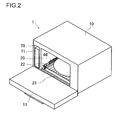
- [FIG. 2] A perspective view showing the exterior, with the door to the heating chamber opened.
- [FIG. 3] A front view, with the door to the heating chamber removed.
- [FIG. 4] A diagram schematically showing an outline of the interior construction.
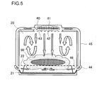
- [FIG. 5] A diagram schematically showing an outline of the interior construction, as viewed from a direction perpendicular to FIG. 4.
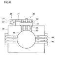
- [FIG. 6] A top view of the heating chamber.
- [FIG. 7] A block diagram showing individual functional blocks.
- [FIG. 8] A diagram similar to FIG. 4, schematically showing an outline of the interior construction in a state different from that shown in FIG 4.
- [FIG. 9] A diagram similar to FIG. 5, schematically showing an outline of the interior construction in a state different from that shown in FIG 5.
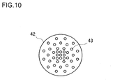
- [FIG. 10] A top view of the floor panel of the sub-cavity.
-
- 1
- steam cooking apparatus
- 20
- heating chamber
- 22
- rack
- 25
- blowing device
- 28
- suction port
- 30
- outer circulation passage
- 40
- sub-cavity
- 41
- steam heating heater
- 42
- floor panel
- 43
- upper jet holes
- 45
- duct
- 46
- side jet holes
- 50
- steam generating device
- 90
- food
- Hereinafter, an embodiment of the present invention will be described with reference to the accompanying drawings.
- The
steam cooking apparatus 1 has acabinet 10 in the shape of a rectangular parallelepiped. On the front face of thecabinet 10, adoor 11 is provided. Thedoor 11 rotates about the bottom edge thereof in a vertical plane. When ahandle 12 fitted in an upper part of thedoor 11 is held and pulled frontward, thedoor 11 changes its position through 90 degrees from a vertical, closed state shown in FIG. 1 to a horizontal, opened state shown in FIG. 2. Amiddle part 11C of thedoor 11 has a pane of heat-resistant glass set therein to form a see-through part. On the left and right of themiddle part 11C, a left-side part 11L and a right-side part 11R, each finished with a metal decoration plate, are arranged symmetrically. On the right-side part 11 R, anoperation panel 13 is provided. - When the
door 11 is opened, the front face of thecabinet 10 appears. In the part of thecabinet 10 corresponding to themiddle part 11C of thedoor 11, aheating chamber 20 is provided. In the part of thecabinet 10 corresponding to the left-side part 11L of thedoor 11, awater tank chamber 70 is provided. In the part of thecabinet 10 corresponding to the right-side part 11R of thedoor 11, a control circuit board is arranged inside, with no opening provided in front thereof. - The
heating chamber 20 has the shape of a rectangular parallelepiped, and is completely open in the front face thereof at which it faces thedoor 11. The other faces of theheating chamber 20 are formed of stainless steel plates. Around theheating chamber 20 and inside thedoor 11, heat insulation is applied. On the floor surface of theheating chamber 20, atray 21 formed of a stainless steel plate is placed, and, above thetray 21, arack 22 formed of stainless steel wire is placed for placingfood 90 thereon. - Inside the
heating chamber 20, steam is present that is circulated through anouter circulation passage 30. shown in FIG. 4 (initially, inside theheating chamber 20, air is dominant; when steam cooking is started, however, the air is gradually replaced with steam; throughout the following description, it is assumed that the gas inside theheating chamber 20 has completely been replaced with steam). - The
outer circulation passage 30 starts at ablowing device 25 provided outside and above theheating chamber 20. The blowingdevice 25 is provided with acentrifugal fan 26, afan casing 27 for housing it, and a motor (unillustrated) for rotating thecentrifugal fan 26. Used as thecentrifugal fan 26 is a sirocco fan. Used as the motor for rotating thecentrifugal fan 26 is a direct-current motor capable of high-speed rotation. - In the rear wall of the
heating chamber 20, in a corner in an upper part thereof, asuction port 28 is provided. Through thesuction port 28, the steam inside theheating chamber 20 is sucked into thefan casing 27. As shown in FIG. 3, thesuction port 28 consists of a plurality of parallel slits arranged one above the next. These slits are increasingly long upward and increasingly short downward so that they together form an opening in the shape of a right-angled triangle. The right-angled corner of the triangle fits the corner of the rear wall of theheating chamber 20. Thus, thesuction port 28 is increasingly widely open toward the upper edge of the rear wall of theheating chamber 20, and is increasingly widely open toward the left edge thereof. - After exiting from the
fan casing 27 through an outlet port thereof, theouter circulation passage 30 is formed largely of pipes having a circular cross-sectional shape. To the outlet port of thefan casing 27, afirst pipe 31 is connected, which has anexhaust port 32 at the other end thereof. To thefirst pipe 31, a short distance on the upstream side of theexhaust port 32, asecond pipe 33 is connected, which is elbow-shaped. A horizontal part of thesecond pipe 33 protrudes into an upper part of a steam generating device 50 (which will be described in detail later) to form asteam suction ejector 34. The outlet end of thesecond pipe 33 is tapered to serve as an inner nozzle of thesteam suction ejector 34. - To the exit of the
steam suction ejector 34, athird pipe 35 is connected, which also forms part of theouter circulation passage 30. The outlet end of thethird pipe 35 is connected to a sub-cavity 40 (which will be described in detail later). To thethird pipe 35, abypass pipe 36 is connected, which branches off thefirst pipe 31. - The sub-cavity 40 is provided above a ceiling part of the
heating chamber 20 and, as viewed in a plan view, above a central part of the ceiling part. The sub-cavity 40 has a circular shape as viewed in a plan view, and, inside the sub-cavity 40, asteam heating heater 41 is arranged as means for heating steam. Thesteam heating heater 41 is built with a sheath heater. In the ceiling part of theheating chamber 20, an opening as large as the sub-cavity 40 is formed, and, in this opening, afloor panel 42 that forms the floor surface of the sub-cavity 40 is fitted. - In the
floor panel 42, upper jet holes 43 are formed. The upper jet holes 43 consist of small holes that are each directed straight downward and that are so located as to spread largely over the entire surface of the panel. Here, the upper jet holes 43 are so located as to spread within a plane, that is, two-dimensionally. It is, however, also possible to form elevations and depressions on thefloor panel 42 so that the locations of the upper jet holes 43 spread quasi-three-dimensionally. - Both the upper and lower surfaces of the
floor panel 42 are finished to be dark-colored through surface treatment such as painting. Instead, thefloor panel 42 may be formed of a metal material whose color grows dark as use progresses; instead, thefloor panel 42 may be formed of a dark-colored ceramic molding. - Instead the floor surface of the sub-cavity 40 being formed with the
floor panel 42 separately provided, the ceiling plate of theheating chamber 20 may, as it is, be shared as the floor surface of the sub-cavity 40. In this case, the part of the ceiling plate corresponding to the sub-cavity 40 has the upper jet holes 43 formed therein, and has the upper and lower surfaces thereof finished to be dark-colored. - Outside the left and right side walls of the
heating chamber 20, small sub-cavities 44 are provided as shown in FIG. 5. The sub-cavities 44 are connected to the sub-cavity 40 throughducts 45 to receive steam from the sub-cavity 40 (see FIGS. 5 and 6). Theducts 45 are formed as pipes having a circular cross-sectional shape. Here, it is preferable to use pipes of stainless steel. - In lower parts of the side walls of the
heating chamber 20, a plurality of side jet holes 46 are formed in positions corresponding to the sub-cavities 44. The side jet holes 46 are small holes that are each directed toward thefood 90 placed inside theheating chamber 20, more precisely, toward under thefood 90. The side jet holes 46 permit steam to be jetted out therethrough toward thefood 90 placed on therack 22. The heights and directions of the side jet holes 46 are so set that the steam blown out reaches under thefood 90. Moreover, the side jet holes 46 are so positioned and/or directed that the steam blown out from the left and right sides meets under thefood 90. - The side jet holes 46 may be formed in a separately provided panel, or may be formed in the side walls of the
heating chamber 20 themselves, with small holes formed directly therein. In this respect, what has been stated above in connection with the upper jet holes 43 equally applies. In contrast to the sub-cavity 40, however, the parts corresponding to the sub-cavities 44 need not be finished to be dark-colored. - The total area of the side jet holes 46 at the left and right sides is made larger than the total area of the upper jet holes 43. Since the side jet holes 46 thus have a large total area, a large amount of steam needs to be supplied thereto. To achieve this, for each sub-cavity 44, a plurality of ducts 45 (in the figures, three of them) are provided.
- Back in FIG. 4, to the upper part of the
heating chamber 20, one end of asteam exhaust pipe 47 is connected. The other end of thesteam exhaust pipe 47 is connected to thefirst pipe 31, immediately inward of theexhaust port 32. Inside thefirst pipe 31, between where it is connected to thesecond pipe 33 and where it is connected to thesteam exhaust pipe 47, adamper 48 is provided that is electrically driven. Thedamper 48 opens and closes the passage leading from the blowingdevice 25 to theexhaust port 32. - Next, the structure of the
steam generating device 50 will be described. Thesteam generating device 50 is provided with acylindrical pot 51 arranged with the center line thereof vertical. Thepot 51 is closed at the top, and, as described previously, has thesteam suction ejector 34 formed in a top part thereof. - The
pot 51 is formed of a metal having good thermal conductivity. Examples of such metals include copper and aluminum. Since copper and its alloys form patina, however, it is possible to use, instead, stainless steel free from the disadvantage of forming patina, through with slightly lower thermal conductivity. - Water is put inside the
pot 51, and is heated with asteam generating heater 52 provided in close contact with the exterior surface of thepot 51. Thesteam generating heater 52 is built with a ring-shaped sheath heater. - As shown in FIG. 6, as viewed in a plan view, the
pot 51 is flat, and is arranged with a flat face thereof placed along the rear wall of theheating chamber 20. Theouter circulation passage 30 has three of thesteam suction ejector 34, and accordingly three of thethird pipe 35 are connected to thesub-cavity 40. - The
pot 51 has a funnel-shaped bottom part, from which awater drain pipe 53 runs downward. Thewater drain pipe 53 has a lower part thereof bent so as to run toward theheating chamber 20 with a slope of a predetermined angle, and, at the lower end, penetrates a side wall of theheating chamber 20 to reach above thetray 21. On the way along thedrain pipe 53, awater drain valve 54 is provided. - The
pot 51 is supplied with water through awater supply pipe 55. Thewater supply pipe 55 is connected to thewater drain pipe 53, above thewater drain valve 54. At the highest part of thewater supply pipe 55, awater level sensor 56 is provided. - From the part where the
water level sensor 56 is provided to the other end thereof, thewater supply pipe 55 is U-shaped, on the way along which part awater supply pump 57 is provided. This end of thewater supply pipe 55 points sideways, and has a funnel-shapedinlet port 58 formed thereat. - Into the
water tank chamber 70, awater tank 71 in the shape of a rectangular parallelepiped having a small lateral width is inserted. From thewater tank 71 runs an elbow-shapedwater supply pipe 72, which is connected to theinlet port 58 of thewater supply pipe 55. - The operation of the
steam cooking apparatus 1 is controlled by acontrol device 80 shown in FIG. 7. Thecontrol device 80 includes a microprocessor and a memory, and controls thesteam cooking apparatus 1 according to a predetermined program. The status of control is indicated in a display portion on theoperation panel 13. Thecontrol device 80 receives operation instructions from various operation keys arranged on theoperation panel 13 as they are operated. On theoperation panel 13, a sound generating device is also arranged that generates various sounds. - Connected to the
control device 80 is not only theoperation panel 13 but also theblowing device 25, thesteam heating heater 41, thedamper 48, thesteam generating heater 52, thewater drain valve 54, thewater level sensor 56, and thewater supply pump 57. Further connected to thecontrol device 80 are: awater level sensor 81 for sensing the amount of water inside thewater tank 71; atemperature sensor 82 for sensing the temperature inside theheating chamber 20; and ahumidity sensor 83 for sensing the humidity inside theheating chamber 20. - The
steam cooking apparatus 1 is operated and operates as follows. First, thedoor 11 is opened, then thewater tank 71 is taken out of thewater tank chamber 70, and then water is poured into the tank through an unillustrated water supply port thereof. Filled with water, thewater tank 71 is then put back into thewater tank chamber 70 and is set in position. When the end of thewater supply pipe 72 is confirmed to have been securely connected to theinlet port 58 of thewater supply pipe 55, thedoor 11 is closed, and then a power key on theoperation panel 13 is pressed to turn the power on. Now, thewater supply pump 57 starts to operate, and water starts to be supplied to thesteam generating device 50. At this point, thewater drain valve 54 is closed. Water collects inside thepot 51 from the bottom thereof up. When the water level there is detected to have reached a predetermined level by thewater level sensor 56, water stops being supplied. - Now, with a predetermined amount of water in the
pot 51, electric power starts to be supplied to thesteam generating heater 52. The water in thepot 51 is heated, through the side wall of thepot 51, by thesteam generating heater 52. - At the same time that electric power starts to be supplied to the
steam generating heater 52, or when the temperature of the water in thepot 51 has reached a predetermined temperature, electric power starts to be supplied also to theblowing device 25 and thesteam heating heater 41. The blowingdevice 25 sucks in the steam in theheating chamber 20, and blows it out into theouter circulation passage 30. Here, the blowing out of steam is achieved with thecentrifugal fan 26, a higher pressure can be produced than with a propeller fan. In addition, since thecentrifugal fan 26 is rotated at a high speed with a direct-current motor, the stream produced has an extremely high flow speed. - The high flow speed of the stream here helps reduce the cross-sectional area of the flow passage in comparison with the flow rate. This permits the pipe that largely forms the
outer circulation passage 30 to have a circular cross-sectional shape and a comparatively small diameter, and thus helps give the outer circulation passage 30 a smaller surface area than when it is formed as a duct having a rectangular cross-sectional shape. Thus, although hot steam passes through it, theouter circulation passage 30 dissipates less heat, enhancing the energy efficiency of thesteam cooking apparatus 1. In a case where theouter circulation passage 30 is wrapped with a heat insulating material, the amount of it needed can be reduced. - At this point, the
damper 48 closes the passage leading from the blowingdevice 25 to theexhaust port 32. The steam blown out of theblowing device 25 under pressure flows through thefirst pipe 31 into thesecond pipe 33, and then flows through thethird pipe 35 into thesub-cavity 40. - When the water in the
pot 51 boils, it generates saturated steam at 100 °C and at one atmosphere. The saturated steam mixes, at thesteam suction ejector 34, with the stream circulated through theouter circulation passage 30. The ejector structure here permits the saturated steam to be sucked up and then out quickly. Moreover, the ejector structure prevents thesteam generating device 50 from being acted upon by a pressure, and thereby permits the saturated steam to be discharged freely. - On the downstream side of the
steam suction ejector 34, steam is blown into thethird pipe 35 from thefirst pipe 31 through thebypass pipe 36. Thebypass pipe 36 thus helps reduce the pressure loss in the circulation passage, and thereby permits thecentrifugal fan 26 to be driven efficiently. - The steam that has exited from the
steam suction ejector 34 flows, at a high speed, into thesub-cavity 40. The steam that has entered the sub-cavity 40 is heated to 300 °C by thesteam heating heater 41, and is thus turned into overheated steam. Part of the overheated steam is jetted out downward through the upper jet holes 43. Another part of the overheated steam flows through theducts 45 into the sub-cavities 44, and is then jetted out sideways through the side jet holes 46. - FIGS. 8 and 9 show the flows of steam as observed when no
food 90 is placed inside theheating chamber 20. Through the upper jet holes 43, steam is jetted out downward so strongly as to reach the floor surface of theheating chamber 20. The steam hits the floor surface and changes its flow direction outward. The steam thus moves out of the downward blow and starts to rise. Since steam, in particular overheated steam, is light, this turning of the flow direction occurs naturally. Consequently, inside theheating chamber 20, convection occurs with a falling stream at the center and a rising stream around, as indicated by arrows in the figure. - To produce effective convection, the upper jet holes 43 are arranged ingeniously. Specifically, as shown in FIG. 10, the upper jet holes 43 are so arranged as to be dense in a central part of the
floor panel 42 and sparse in a peripheral part thereof. This weakens the strength of the downward blow of steam in the peripheral part of thefloor panel 42 so as not to hamper the rise of steam, and thus helps produce more effective convection. - Through the side jet holes 46, steam is jetted out sideways. The steam meets in a central part of the
heating chamber 20, and then enters the convection produced by the steam from the upper jet holes 43. The steam flowing by convection is partly sucked out through thesuction port 28. The steam then circulates through theouter circulation passage 30 to the sub-cavity 40, and then returns to theheating chamber 20. In this way, the steam inside theheating chamber 20 repeatedly flows out into theouter circulation passage 30 and then back into theheating chamber 20. - As time passes, the amount of steam inside the
heating chamber 20 increases. Excessive steam is exhausted out of theheating chamber 20 through thesteam exhaust pipe 47 and theexhaust port 32. If the steam is exhausted, as it is, inside thecabinet 10, condensation occurs inside thecabinet 10, leading to undesirable results such as formation of rust and leakage of electric current. If the steam is exhausted, as it is, outside thecabinet 10, condensation occurs on a wall surface of a kitchen, leading to growth of mold. To avoid these inconveniences, the steam is condensed by being passed through a maze-like condensation passage (unillustrated). The water dripping out of the condensation passage is collected in thetray 21, so as to be disposed of, along with water produced otherwise, after the completion of cooking. - When overheated steam starts to be jetted out, the temperature inside the
heating chamber 20 rises quickly. When thetemperature sensor 82 detects that the temperature inside theheating chamber 20 has reached the range of temperature in which cooking is possible, thecontrol device 80 indicates a corresponding message on theoperation panel 13 and sounds an alert. Notified with these message and alert that thesteam cooking apparatus 1 is ready to cook, the user opens thedoor 11, and putsfood 90 in theheating chamber 20. - When the
door 11 is about to be opened, thecontrol device 80 switches thedamper 48 into a state in which it opens the passage leading from the blowingdevice 25 to theexhaust port 32. The steam inside theheating chamber 20 is sucked out by the blowingdevice 25 and exhausted out through theexhaust port 32. The steam blown out of theblowing device 25 under pressure flows straight to theexhaust port 32, and thus almost no part of the steam flows to thesteam generating device 50. This reduces the amount of steam that flows into the sub-cavity 40, and thus now the jetting out, if ever, of steam through the upper jet holes 43 and the side jet holes 46 is extremely weak. This prevents the user from getting exposed to and burnt with steam on the face or hand. As long as thedoor 11 is open, thedamper 48 opens the passage leading to theexhaust port 32. - Here, if the
blowing device 25 is started all over from a resting state to achieve exhaustion through theexhaust port 32, a time lag arises until it reaches a steadily blowing state. In this embodiment, the blowingdevice 25 is already operating, and thus no time lag arises. Moreover, the stream that has thus far been circulating through theheating chamber 20 and theouter circulation passage 30 becomes, as it is, the stream exhausted out through theexhaust port 32. Thus, no time lag arises even for changing the direction of the stream. This makes it possible to quickly exhaust the steam inside theheating chamber 20 and thereby to shorten the time for which thedoor 11 needs to be kept inhibited from being opened. - When the user is about to open the
door 11, this condition can be recognized by thecontrol device 80, for example, in the following manner. A latch for keeping thedoor 11 closed is provided between thecabinet 10 and thedoor 11, and a latch lever for unlocking the latch is provided on the ahandle 12 so as to be exposed out of it. A switch that opens and closes as the latch or the latch lever is operated is arranged inside thedoor 11 or the ahandle 12 so that, when the user grips thehandle 12 and the latch lever to unlock, the switch transmits a signal to thecontrol device 80. - When
food 90 is placed on therack 22 and thedoor 11 is closed, thedamper 48 is switched back to a state in which it closes the passage leading to theexhaust port 32. Now, steam starts to flow into the sub-cavity 40 again, and overheated steam starts to be jetted out through the upper jet holes 43 and the side jet holes 46 again, starting the cooking of thefood 90. - Heated to about 300 °C and jetted out through the upper jet holes 43, the overheated steam hits the
food 90 and delivers heat thereto. In this process, the temperature of the steam drops to about 250 °C. The overheated steam that has touched the surface of thefood 90 condenses on the surface of thefood 90 and thereby releases latent heat. This too heats thefood 90. - As shown in FIGS. 4 and 5, after delivering heat to the
food 90, the steam changes its direction outward and moves out of the downward blow. Since steam is light as described previously, having moved out of the downward blow, the steam starts to rise, producing convection inside theheating chamber 20 as indicated by arrows. This convection maintains the temperature inside theheating chamber 20, and keeps thefood 90 hit by the overheated steam just heated in the sub-cavity 40, permitting a large amount of heat to be applied quickly to thefood 90. - The steam jetted out sideways through the side jet holes 46 reaches, from the left and right sides, under the
rack 22 and meets under thefood 90. Although the steam jetted out through the side jet holes 46 is directed originally in directions tangential to the surface of thefood 90, as a result of the steam from the left and right sides meeting, it does not flow straight on, but stagnates and fills under thefood 90. The steam thus behaves as if blown in directions normal to the surface of thefood 90. This ensures that the heat of steam is delivered to the lower part of thefood 90. - As described above, with the steam from the side jet holes 46, the part of the
food 90 that is not hit by the steam from the upper jet holes 43 is as well cooked as the upper part. This contributes to an evenly-cooked, neat-looking result. Moreover, thefood 90 receives heat evenly from around the surface thereof. Thus, thefood 90 is heated to the center sufficiently in a short time. - The steam from the side jet holes 46, too, originally has a temperature of about 300 °C, and, after it hits the
food 90, its temperature drops to about 250 °, during which process the steam delivers heat to thefood 90. Moreover, when the steam condenses on the surface of thefood 90, it releases latent heat, and thereby heats thefood 90. - After delivering heat to the lower part of the
food 90, the steam from the side jet holes 46 enters the convection produced by the steam from the upper jet holes 43. The steam flowing by convection is partly sucked out through thesuction port 28. The steam then circulates through theouter circulation passage 30 to the sub-cavity 40, and then returns to theheating chamber 20. In this way, the steam inside theheating chamber 20 repeatedly flows out into theouter circulation passage 30 and then back into theheating chamber 20. - The side jet holes 46 are located away from the sub-cavity 40, and are therefore located disadvantageously from the perspective of jetting out steam. Nevertheless, as a result of the total area of the left and right side jet holes 46 being larger than the total area of the upper jet holes 43, a sufficient amount of steam can be guided to the side jet holes 46, permitting the upper and lower parts of the
food 90 to be heated more evenly. - Since the
food 90 is heated while the gas inside theheating chamber 20 is circulated, thesteam cooking apparatus 1 operates with high energy efficiency. Moreover, since the overheated steam from above is jetted out downward through the plurality of upper jet holes 43 that are so located as to spread largely over theentire floor panel 42, largely theentire food 90 is enveloped in the steam from above. As a result of overheated steam hitting thefood 90, and this hitting taking place over a large area, the heat of overheated steam is quickly delivered to thefood 90. Moreover, as a result of the steam having entered the sub-cavity 40 being heated by thesteam heating heater 41 and thus expanding, the steam is jetted out with increased strength, and thus hits thefood 90 at an increased speed. This permits thefood 90 to be heated further quickly. - The
centrifugal fan 26 can generate a pressure higher than a propeller fan, and thus helps increase the strength with which steam is jetted out through the upper jet holes 43. This permits overheated steam to be jetted out so strongly as to reach the floor surface of theheating chamber 20, and thus permits thefood 90 to be heated intensely. Thecentrifugal fan 26 is rotated at a high speed with a direct-current motor to produce a strong stream. This helps enhance the benefits mentioned above. - Moreover, the blowing
device 25 producing a strong stream greatly helps to quickly exhaust steam through theexhaust port 32 when thedoor 11 is opened. - The upper surface of the
floor panel 42 of the sub-cavity 40 is dark-colored, and thus absorbs the heat radiated from thesteam heating heater 41 well. The heat thus absorbed by thefloor panel 42 is then, through the lower surface thereof also dark-colored, radiated to theheating chamber 20. This reduces the rise in the temperatures inside and on the exterior surface of the sub-cavity 40, enhancing safety. Moreover, as a result of the heat radiated from thesteam heating heater 41 being conducted through thefloor panel 42 to theheating chamber 20, theheating chamber 20 is heated more efficiently. As viewed in a plan view, thefloor panel 42 may have a circular shape, or may have a rectangular shape geometrically similar to theheating chamber 20 as viewed in a plan view. As described previously, the ceiling wall of theheating chamber 20 may be shared as the floor panel of the sub-cavity 40. - In a case where the
food 90 is meat or the like, as temperature rises, melted fat may drip down. In a case where thefood 90 is a beverage or the like in a container, when it boils, part of it may boil over. Anything that drips down or boils over in such a way is collected in thetray 21, so as to be disposed of after the completion of cooking. - As the
steam generating device 50 continues generating steam, the water level inside thepot 51 falls. When thewater level sensor 56 detects that the water level has fallen to a predetermined level, thecontrol device 80 restarts the operation of thewater supply pump 57. Thewater supply pump 57 sucks up water from thewater tank 71 to supply as much water as has evaporated. When thewater level sensor 56 detects that the water level inside thepot 51 has risen to a predetermined level, thecontrol device 80 stops the operation of thewater supply pump 57. - On completion of cooking, the
control device 80 indicates a corresponding message on theoperation panel 13 and sounds an alert. Notified with these message and alert that thesteam cooking apparatus 1 has finished cooking, the user opens thedoor 11, and takes thefood 90 out of theheating chamber 20. At this point also, thedamper 48 is so switched that the steam inside theheating chamber 20 is exhausted through theexhaust port 32. This permits the user to take out thefood 90 safely. - In a case where there is a long pause before cooking is performed next time, or in a case where, in a cold-climate area, no cooking is scheduled until the morning the next day, after the completion of cooking, the
water drain valve 54 is opened through operation on theoperation panel 13 to remove water from thepot 51. This prevents the water inside thepot 51 from being infected with germs, algae, and the like and from freezing. - In the embodiment described above, the steam inside the
heating chamber 20 is circulated through theouter circulation passage 30 and the sub-cavity 40 to flow back to theheating chamber 20. This, however, may be modified. For example, the sub-cavity 40 may be supplied with new steam all the time while the steam spilling out of theheating chamber 20 is kept exhausted through thesteam exhaust pipe 47. - It should be understood that, in the embodiment described above, many other modifications and variations are possible within the scope of the present invention.
- The present invention finds wide application in cooking apparatuses in general that perform cooking by use of overheated steam, irrespective of whether they are designed for household or business use.
Claims (8)
- A steam cooking apparatus comprising:(a) a heating chamber in which food is placed;(b) a steam generating device;(c) an upper jet hole that is provided in a ceiling part of the heating chamber and through which steam supplied from the steam generating device is jetted toward the food placed in the heating chamber; and(d) a side jet hole that is provided in a lower part of a side wall of the heating chamber at one or both sides thereof and through which steam supplied from the steam generating device is jetted toward the food.
- The steam cooking apparatus of claim 1,
wherein the food is supported in a state floating above a floor surface of the heating chamber by supporting means, and, through the side jet hole, steam is blown toward under the food. - The steam cooking apparatus of claim 2,
wherein the side jet hole is so positioned and/or directed that the steam jetted out from each side meets under the food. - The steam cooking apparatus of one of claims 1 to 3,
wherein steam generated by the steam generating device is introduced into a sub-cavity provided adjacent to the heating chamber, the steam is then heated inside the sub-cavity by heating means, and the so heated steam is then distributed between the upper jet hole and the side jet hole. - The steam cooking apparatus of claim 4,
wherein the steam heated inside the sub-cavity is guided to the side jet hole through a duct formed of a pipe. - The steam cooking apparatus of claim 4,
wherein the sub-cavity is provided in the ceiling part of the heating chamber. - The steam cooking apparatus of claim 6,
wherein the upper jet hole is provided in a floor panel of the sub-cavity. - The steam cooking apparatus of claim 1,
wherein a total area of the side jet hole is larger than a total area of the upper jet hole.
Applications Claiming Priority (2)
| Application Number | Priority Date | Filing Date | Title |
|---|---|---|---|
| JP2004001842A JP3737094B2 (en) | 2004-01-07 | 2004-01-07 | Steam cooker |
| PCT/JP2004/018247 WO2005066544A1 (en) | 2004-01-07 | 2004-12-08 | Steam cooking apparatus |
Publications (2)
| Publication Number | Publication Date |
|---|---|
| EP1710508A1 true EP1710508A1 (en) | 2006-10-11 |
| EP1710508A4 EP1710508A4 (en) | 2017-02-01 |
Family
ID=34747005
Family Applications (1)
| Application Number | Title | Priority Date | Filing Date |
|---|---|---|---|
| EP04821013.2A Withdrawn EP1710508A4 (en) | 2004-01-07 | 2004-12-08 | Steam cooking apparatus |
Country Status (5)
| Country | Link |
|---|---|
| US (1) | US7802564B2 (en) |
| EP (1) | EP1710508A4 (en) |
| JP (1) | JP3737094B2 (en) |
| CN (1) | CN100464126C (en) |
| WO (1) | WO2005066544A1 (en) |
Cited By (1)
| Publication number | Priority date | Publication date | Assignee | Title |
|---|---|---|---|---|
| EP2469191A1 (en) | 2010-12-23 | 2012-06-27 | Miele & Cie. KG | Cooking device |
Families Citing this family (21)
| Publication number | Priority date | Publication date | Assignee | Title |
|---|---|---|---|---|
| KR100953234B1 (en) | 2005-07-25 | 2010-04-16 | 샤프 가부시키가이샤 | Trays for heated cookers and cookers |
| JP2007064530A (en) * | 2005-08-30 | 2007-03-15 | Toshiba Corp | Cooker |
| JP4641005B2 (en) * | 2006-05-29 | 2011-03-02 | シャープ株式会社 | Cooker |
| JP4311688B2 (en) * | 2006-11-02 | 2009-08-12 | シャープ株式会社 | Exhaust steam diluting apparatus and cooking device equipped with the same |
| JP2007187443A (en) * | 2007-04-23 | 2007-07-26 | Sharp Corp | Cooker |
| CN102472498B (en) * | 2009-07-30 | 2015-06-24 | 夏普株式会社 | Cooking device |
| JP4843100B1 (en) * | 2010-08-31 | 2011-12-21 | シャープ株式会社 | Cooker |
| EP2697569B1 (en) * | 2011-04-15 | 2017-07-12 | BSH Hausgeräte GmbH | Steam cooking appliance, in particular a steam oven |
| US9872581B2 (en) | 2012-05-16 | 2018-01-23 | Bsh Home Appliances Corporation | Home appliance with recessed water vessel housing |
| US10119708B2 (en) * | 2013-04-23 | 2018-11-06 | Alto-Shaam, Inc. | Oven with automatic open/closed system mode control |
| EP4063730B1 (en) * | 2014-01-15 | 2024-04-03 | Electrolux Appliances Aktiebolag | Steam oven having a l-shaped steam generator |
| US9777417B2 (en) | 2015-01-20 | 2017-10-03 | Bekir Beyer | Fluid regulating apparatus |
| JP5979802B1 (en) * | 2015-03-25 | 2016-08-31 | シャープ株式会社 | Cooker |
| TWI568354B (en) * | 2015-11-19 | 2017-02-01 | 舞蘊有限公司 | Floating barbecue appliance and barbecue method thereof |
| WO2017116352A1 (en) * | 2015-12-29 | 2017-07-06 | Arcelik Anonim Sirketi | An oven comprising a water tank |
| US10208417B2 (en) * | 2016-04-13 | 2019-02-19 | Bekir Beyer | Dye exhaustion and dryer apparatus |
| DE102016215650A1 (en) * | 2016-08-19 | 2018-02-22 | BSH Hausgeräte GmbH | Haushaltsgargerät |
| US11118293B2 (en) | 2019-03-08 | 2021-09-14 | Bekir Beyer | Dye exhaustion and dryer apparatus |
| CN114098418B (en) * | 2020-08-28 | 2023-03-21 | 佛山市顺德区美的电热电器制造有限公司 | Cooking appliance, control method, control device and computer-readable storage medium |
| CN112656201B (en) * | 2020-12-18 | 2022-02-11 | 珠海格力电器股份有限公司 | Lunch box |
| EP4018892A1 (en) * | 2020-12-22 | 2022-06-29 | Koninklijke Philips N.V. | Cooking apparatus |
Family Cites Families (21)
| Publication number | Priority date | Publication date | Assignee | Title |
|---|---|---|---|---|
| US2719211A (en) * | 1954-02-25 | 1955-09-27 | Albert M Lewis | Food steamer |
| JPS5459372A (en) * | 1977-10-13 | 1979-05-12 | Matsushita Electric Industrial Co Ltd | Steam oven |
| JPS54127769A (en) * | 1978-03-27 | 1979-10-03 | Mitsubishi Electric Corp | Cooker |
| JPS56148502A (en) | 1980-04-19 | 1981-11-18 | Meinan Machinery Works | Method of supplying veneer on which adhesive is applied |
| JPS56148502U (en) * | 1981-03-26 | 1981-11-09 | ||
| US4460822A (en) * | 1982-02-01 | 1984-07-17 | Market Forge, Div. Of Beatrice Foods Co. | Pressureless steam cooker |
| JPS58194747U (en) * | 1982-06-18 | 1983-12-24 | 大畠 隆 | processed food storage |
| US4552123A (en) * | 1984-12-12 | 1985-11-12 | Thermo Electron Corporation | Gas-fired steam cooker |
| FR2619613B1 (en) * | 1987-08-18 | 1989-11-24 | Grandi Rene | MODULAR FLOWING STEAM COOKING UNIT DEVICE WITH PREFERENTIAL PATH WITH SUPERHEATERS AND CONDENSATION CORRIDOR OF RESIDUAL VAPORS |
| US5215000A (en) * | 1988-03-29 | 1993-06-01 | A.R.M.I.N.E.S. | Method and apparatus for thermal treatment of alimentary substances |
| US4951648A (en) * | 1989-03-23 | 1990-08-28 | Tecogen, Inc. | Conveyor oven |
| JPH09126458A (en) * | 1995-11-01 | 1997-05-16 | Tokyo Gas Co Ltd | Convection oven |
| US6454176B1 (en) * | 1999-09-28 | 2002-09-24 | Henny Penny Corporation | Holding cabinet with closed-loop humidity control system and method for controlling humidity in a holding cabinet |
| JP2002153380A (en) * | 2000-11-17 | 2002-05-28 | Nakanishi Mfg Co Ltd | Cooking and heating device |
| JP2003302049A (en) * | 2002-04-09 | 2003-10-24 | Sharp Corp | Cooking device |
| JP3894825B2 (en) * | 2001-12-28 | 2007-03-22 | シャープ株式会社 | Cooker |
| US8006685B2 (en) * | 2002-07-05 | 2011-08-30 | Turbochef Technologies, Inc. | Re-circulating oven with gas clean-up |
| EP1534999B1 (en) * | 2002-07-05 | 2017-11-01 | TurboChef Technologies, Inc. | Speed cooking oven |
| JP2004138346A (en) | 2002-10-18 | 2004-05-13 | Matsushita Electric Ind Co Ltd | Superheated steam cooking device |
| JP4334201B2 (en) | 2002-11-11 | 2009-09-30 | シャープ株式会社 | Cooker |
| KR20060070910A (en) * | 2004-12-21 | 2006-06-26 | 삼성전자주식회사 | Electric oven |
-
2004
- 2004-01-07 JP JP2004001842A patent/JP3737094B2/en not_active Expired - Fee Related
- 2004-12-08 EP EP04821013.2A patent/EP1710508A4/en not_active Withdrawn
- 2004-12-08 US US10/583,974 patent/US7802564B2/en not_active Expired - Fee Related
- 2004-12-08 WO PCT/JP2004/018247 patent/WO2005066544A1/en not_active Ceased
- 2004-12-08 CN CNB2004800400865A patent/CN100464126C/en not_active Expired - Fee Related
Non-Patent Citations (1)
| Title |
|---|
| See references of WO2005066544A1 * |
Cited By (1)
| Publication number | Priority date | Publication date | Assignee | Title |
|---|---|---|---|---|
| EP2469191A1 (en) | 2010-12-23 | 2012-06-27 | Miele & Cie. KG | Cooking device |
Also Published As
| Publication number | Publication date |
|---|---|
| JP3737094B2 (en) | 2006-01-18 |
| CN1902444A (en) | 2007-01-24 |
| EP1710508A4 (en) | 2017-02-01 |
| CN100464126C (en) | 2009-02-25 |
| US7802564B2 (en) | 2010-09-28 |
| WO2005066544A1 (en) | 2005-07-21 |
| US20080223352A1 (en) | 2008-09-18 |
| JP2005195247A (en) | 2005-07-21 |
Similar Documents
| Publication | Publication Date | Title |
|---|---|---|
| US7802564B2 (en) | Steam cooking apparatus | |
| US8042532B2 (en) | Heat-cooking apparatus | |
| US7759615B2 (en) | Steam cooking apparatus | |
| JP3781759B2 (en) | Steam cooker | |
| RU2422731C2 (en) | Device for exhaust steam thinning and boiling apparatus with such device | |
| EP1655542B1 (en) | Steam cooker | |
| JP2005098670A (en) | Cooker | |
| EP1729061A1 (en) | Steam generator and steam cooker mounting it | |
| JP3795050B2 (en) | Steam cooker | |
| JP2008008539A (en) | Cooker | |
| JP4190425B2 (en) | Steam cooker | |
| JP4381187B2 (en) | Steam cooker | |
| JP4416610B2 (en) | Superheated steam cooker | |
| JP4381189B2 (en) | Steam cooker | |
| JP4229860B2 (en) | Steam cooker | |
| JP4229861B2 (en) | Steam cooker | |
| JP4473043B2 (en) | Steam cooker | |
| JP4403092B2 (en) | Cooker | |
| JP2005069521A (en) | Steam generator and steam cooker equipped with the same | |
| JP4376223B2 (en) | Steam cooker | |
| JP4399388B2 (en) | Cooker | |
| JP2007017073A (en) | Cooker | |
| JP2006046708A (en) | Steam cooker |
Legal Events
| Date | Code | Title | Description |
|---|---|---|---|
| PUAI | Public reference made under article 153(3) epc to a published international application that has entered the european phase |
Free format text: ORIGINAL CODE: 0009012 |
|
| 17P | Request for examination filed |
Effective date: 20060803 |
|
| AK | Designated contracting states |
Kind code of ref document: A1 Designated state(s): DE FR GB |
|
| DAX | Request for extension of the european patent (deleted) | ||
| RBV | Designated contracting states (corrected) |
Designated state(s): DE FR GB |
|
| RA4 | Supplementary search report drawn up and despatched (corrected) |
Effective date: 20170105 |
|
| RIC1 | Information provided on ipc code assigned before grant |
Ipc: F24C 15/32 20060101AFI20161223BHEP |
|
| STAA | Information on the status of an ep patent application or granted ep patent |
Free format text: STATUS: REQUEST FOR EXAMINATION WAS MADE |
|
| STAA | Information on the status of an ep patent application or granted ep patent |
Free format text: STATUS: THE APPLICATION IS DEEMED TO BE WITHDRAWN |
|
| 18D | Application deemed to be withdrawn |
Effective date: 20170404 |