EP1710472A1 - Auto-tensioner for accessories - Google Patents
Auto-tensioner for accessories Download PDFInfo
- Publication number
- EP1710472A1 EP1710472A1 EP05704107A EP05704107A EP1710472A1 EP 1710472 A1 EP1710472 A1 EP 1710472A1 EP 05704107 A EP05704107 A EP 05704107A EP 05704107 A EP05704107 A EP 05704107A EP 1710472 A1 EP1710472 A1 EP 1710472A1
- Authority
- EP
- European Patent Office
- Prior art keywords
- cylinder
- pressure
- chamber
- belt
- rod
- Prior art date
- Legal status (The legal status is an assumption and is not a legal conclusion. Google has not performed a legal analysis and makes no representation as to the accuracy of the status listed.)
- Withdrawn
Links
Images


Classifications
-
- F—MECHANICAL ENGINEERING; LIGHTING; HEATING; WEAPONS; BLASTING
- F16—ENGINEERING ELEMENTS AND UNITS; GENERAL MEASURES FOR PRODUCING AND MAINTAINING EFFECTIVE FUNCTIONING OF MACHINES OR INSTALLATIONS; THERMAL INSULATION IN GENERAL
- F16H—GEARING
- F16H7/00—Gearings for conveying rotary motion by endless flexible members
- F16H7/08—Means for varying tension of belts, ropes or chains
- F16H7/10—Means for varying tension of belts, ropes or chains by adjusting the axis of a pulley
- F16H7/12—Means for varying tension of belts, ropes or chains by adjusting the axis of a pulley of an idle pulley
- F16H7/1209—Means for varying tension of belts, ropes or chains by adjusting the axis of a pulley of an idle pulley with vibration damping means
- F16H7/1236—Means for varying tension of belts, ropes or chains by adjusting the axis of a pulley of an idle pulley with vibration damping means of the fluid and restriction type, e.g. dashpot
-
- F—MECHANICAL ENGINEERING; LIGHTING; HEATING; WEAPONS; BLASTING
- F16—ENGINEERING ELEMENTS AND UNITS; GENERAL MEASURES FOR PRODUCING AND MAINTAINING EFFECTIVE FUNCTIONING OF MACHINES OR INSTALLATIONS; THERMAL INSULATION IN GENERAL
- F16H—GEARING
- F16H7/00—Gearings for conveying rotary motion by endless flexible members
- F16H7/08—Means for varying tension of belts, ropes or chains
- F16H2007/0802—Actuators for final output members
- F16H2007/0806—Compression coil springs
-
- F—MECHANICAL ENGINEERING; LIGHTING; HEATING; WEAPONS; BLASTING
- F16—ENGINEERING ELEMENTS AND UNITS; GENERAL MEASURES FOR PRODUCING AND MAINTAINING EFFECTIVE FUNCTIONING OF MACHINES OR INSTALLATIONS; THERMAL INSULATION IN GENERAL
- F16H—GEARING
- F16H7/00—Gearings for conveying rotary motion by endless flexible members
- F16H7/08—Means for varying tension of belts, ropes or chains
- F16H2007/0802—Actuators for final output members
- F16H2007/0812—Fluid pressure
- F16H2007/0814—Fluid pressure with valves opening on surplus pressure
-
- F—MECHANICAL ENGINEERING; LIGHTING; HEATING; WEAPONS; BLASTING
- F16—ENGINEERING ELEMENTS AND UNITS; GENERAL MEASURES FOR PRODUCING AND MAINTAINING EFFECTIVE FUNCTIONING OF MACHINES OR INSTALLATIONS; THERMAL INSULATION IN GENERAL
- F16H—GEARING
- F16H7/00—Gearings for conveying rotary motion by endless flexible members
- F16H7/08—Means for varying tension of belts, ropes or chains
- F16H7/0848—Means for varying tension of belts, ropes or chains with means for impeding reverse motion
- F16H2007/0859—Check valves
Definitions
- This invention relates to an auto-tensioner for engine accessories for keeping a constant tension in a belt for driving engine accessories such as an alternator.
- a belt transmission system for driving engine accessories includes an auto-tensioner for keeping a constant tension in the accessory driving belt by applying an adjusting force to the belt.
- Patent document 1 discloses an auto-tensioner for engine accessories of this type.
- the auto-tensioner disclosed in Patent document 1 includes a cylinder in which a sleeve having a bottom is received.
- a seal member such as an oil seal is mounted to the cylinder at its open top end to prevent leakage of hydraulic oil in the cylinder.
- a rod slidably extends through the seal member and is biased outwardly of the cylinder by a return spring. The pushing force applied to the rod from the belt is dampened by a hydraulic damper mounted in the cylinder.
- the hydraulic damper includes a plunger slidably mounted in the sleeve and dividing the interior of the cylinder into a pressure chamber and a reservoir chamber.
- the plunger is formed with a passage through which the pressure chamber communicates with the reservoir chamber.
- a check valve is provided at the passage to close the passage when the pressure in the pressure chamber exceeds the pressure in the reservoir chamber.
- An object of this invention is to provide an auto-tensioner for engine accessories which can smoothly follow shrinkage and expansion of the belt and which can minimize the amplitude of vibration of the belt.
- an auto-tensioner for engine accessories comprising a cylinder having an open top end, a sleeve having a bottom and inserted in the cylinder, a seal member mounted to the cylinder at the open top end to prevent leakage of hydraulic oil in the cylinder, a rod slidably extending through the seal member, a plunger connected to a bottom end of the rod so as to be slidable in the sleeve, the plunger defining a reservoir chamber and a pressure chamber in the cylinder over and under the plunger, respectively, and having a passage through which the pressure chamber communicates with the reservoir chamber, a check valve provided at the passage to close the passage when the pressure in the pressure chamber exceeds the pressure in the reservoir chamber, and a return spring mounted around the cylinder to bias the rod outwardly of the cylinder, characterized in that a return chamber is defined under the sleeve so as to communicate with the reservoir chamber, the bottom of the sleeve being formed with a valve hole through which
- valve hole in the bottom of the sleeve, and providing the relief valve at the valve hole, even if the oil leak gap defined between the sliding surfaces of the sleeve and the plunger is reduced to reduce the amount of oil leakage, thereby increasing the damping force of the hydraulic damper, by opening the relief valve, it is possible to effectively absorb expansion of the belt due to fluctuations in loads on engine accessories or the revolving speed of the engine. This improves the responsiveness of the auto-tensioner for engine accessories according to the invention.
- the rod When the tension in the belt increases, the rod is pushed into the cylinder. If the pressure in the pressure chamber due to the pushing force applied to the rod exceeds the set pressure of the relief valve, the relief valve opens, thus preventing an excessive increase in the tension of the belt when fluctuations in revolving speed of the engine is large while the engine revolving speed is low. Also, by applying a pushing force to the rod which is large enough to produce a pressure in the pressure chamber higher than the set pressure of the relief valve, the rod can be smoothly pushed into the cylinder, so that the engine accessory driving belt can be easily replaced.
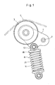
- Fig. 1 shows a belt tension adjusting device including an auto-tensioner A for engine accessories according to the present invention.
- the tension adjusting device includes a pulley arm 1 pivotable about a shaft 2.
- An adjusting force of the auto-tensioner A for engine accessories is applied to the pulley arm 1 to press a tension pulley 3 rotatably supported by the pulley arm 1 against an engine accessory driving belt 4.
- the auto-tensioner A for engine accessories includes a cylinder 11 made of aluminum alloy and having a closed bottom, and a steel sleeve 12 having a closed bottom and received in the cylinder 11.
- a seal member 13 in the form of an oil seal is mounted to the cylinder 11 near its top opening.
- An air gap 14 is present in the cylinder 11 between the seal member 13 and hydraulic oil in the cylinder 11.
- the seal member 13 has a rod inserting hole 15 through which a rod 16 slidably extends.
- An arm coupling piece 17 coupled to the pulley arm 1 is mounted to the top of the rod 16.
- the arm coupling piece 17 includes a spring seat 18 and a cylindrical dust cover 19 surrounding the outer periphery of the cylinder 11 at its top portion.
- a return spring 21 is mounted between the spring seat 18 and a spring seat 20 provided on the outer periphery of the cylinder 11 at its lower portion to bias the rod 16 outwardly of the cylinder 11.
- a wear ring 22 is mounted to a portion of the rod 16 disposed inside the cylinder 11.
- the wear ring 22 is in sliding contact with the inner periphery of the cylinder 11, thereby supporting the intermediate portion of the rod 16.
- a hydraulic damper 23 is mounted in the cylinder 11 for dampening the pushing force applied to the rod 16.
- the hydraulic damper 23 includes a plunger 24 slidable along the inner periphery of the sleeve 12 and connected to the bottom of the rod 16.
- the plunger 24 divides the interior of the cylinder 11 into a pressure chamber 25 and a reservoir chamber 26.
- the plunger 24 is formed with a passage 27 through which the pressure chamber 25 communicates with the reservoir chamber 26.
- a check valve 28 is provided at the passage 27.
- the check valve 28 comprises a check ball 28a for closing and opening the passage 27, a retainer 28b for restricting the degree of opening of the passage 27 by the check ball 28a, and a plunger spring 28c biasing the retainer 28b against the bottom surface of the plunger 24.
- the check valve 28 is configured to close the passage 27 when the pressure in the pressure chamber 25 exceeds the pressure in the reservoir chamber 26.
- a return chamber 29 is formed in the inner bottom surface of the cylinder 11 under the bottom end of the sleeve 12.
- the return chamber 29 communicates with the reservoir chamber 26 through a plurality of axial grooves formed in the outer periphery of the sleeve 12.
- the return chamber 29 may be communicated with the reservoir chamber 26 through a plurality of axial grooves formed in the inner periphery of the cylinder 11.
- a valve hole 31 is formed through which the pressure chamber 25 communicates with the return chamber 29.
- a relief valve 32 is provided at the valve hole 31.
- the relief valve 32 comprises a ball 33 for closing and opening the valve hole 31, and a spring 34 biasing the ball 33 toward the valve hole 31.
- the relief valve 32 is configured to open the valve hole 31 when the pressure in the pressure chamber 25 exceeds a set pressure.
- the pressure of the hydraulic oil in the pressure chamber 25 gradually increases with the pushing force applied to the rod 16. If the pressure in the pressure chamber 25 exceeds the set pressure of the relief valve 32, the relief valve 32 opens the valve hole 31, allowing hydraulic oil in the pressure chamber 25 to flow through the valve hole 31 into the return chamber 29, and then into the reservoir chamber 26 through the passages 30. This prevents the pressure in the pressure chamber 25 from exceeding the set pressure of the relief valve 32, thus preventing an excessive increase in the tension of the belt 4.
- the auto-tensioner for engine accessories can smoothly follow fluctuations in tension of the belt 4 due to fluctuations in the load on the engine accessories.
- the rod 16 is pushed into the cylinder 11 by pressing the tension pulley 3 so that tension pulley 3 is not pressed against the belt 4. In this state, the belt 4 is replaced.
- the auto-tensioner for engine accessories according to the present invention can be shrunk by applying a pushing force greater than the set pressure of the relief valve 32 to the rod 16, replacement of the belt 4 is extremely easy.
Landscapes
- Engineering & Computer Science (AREA)
- General Engineering & Computer Science (AREA)
- Mechanical Engineering (AREA)
- Devices For Conveying Motion By Means Of Endless Flexible Members (AREA)
Abstract
An auto-tensioner for engine accessories is proposed which can smoothly follow shrinkage and expansion of a belt and which can minimize the amplitude of vibration of the belt.
A seal member 13 is mounted to a cylinder 11 at its top open end. A rod 16 slidably extends through the seal member 13. A return spring 21 biases the rod 16 outwardly. A plunger 24 is slidably received in a sleeve 12 having a bottom and received in the cylinder 11, and is connected to the bottom of the rod 16. The plunger 24 has a passage 27 through which a lower pressure chamber 25 and an upper reservoir chamber 26 communicate with each other. A check valve 28 is provided at the passage 27. A return chamber 29 is defined under the sleeve 12 so as to communicate with the reservoir chamber 26. In the bottom of the sleeve 12, a valve hole 31 is formed through which the return chamber 29 communicates with the pressure chamber 25. A relief valve 32 is provided at the valve hole 31. The relief valve 32 prevents the pressure in the pressure chamber 25 from rising above a set pressure, thereby preventing an excessive increase in the tension of the belt. This makes it possible to reduce oil leak gaps defined between the sliding surfaces of the sleeve 12 and the plunger 24, thereby keeping the vibration amplitude of the belt. This improves the responsiveness of the auto-tensioner to the expansion of the belt while the relief valve 32 is open.
Description
- This invention relates to an auto-tensioner for engine accessories for keeping a constant tension in a belt for driving engine accessories such as an alternator.
- Ordinarily, a belt transmission system for driving engine accessories includes an auto-tensioner for keeping a constant tension in the accessory driving belt by applying an adjusting force to the belt.
-
Patent document 1 discloses an auto-tensioner for engine accessories of this type. The auto-tensioner disclosed inPatent document 1 includes a cylinder in which a sleeve having a bottom is received. A seal member such as an oil seal is mounted to the cylinder at its open top end to prevent leakage of hydraulic oil in the cylinder. A rod slidably extends through the seal member and is biased outwardly of the cylinder by a return spring. The pushing force applied to the rod from the belt is dampened by a hydraulic damper mounted in the cylinder. - The hydraulic damper includes a plunger slidably mounted in the sleeve and dividing the interior of the cylinder into a pressure chamber and a reservoir chamber. The plunger is formed with a passage through which the pressure chamber communicates with the reservoir chamber. A check valve is provided at the passage to close the passage when the pressure in the pressure chamber exceeds the pressure in the reservoir chamber. Thus, the pushing force applied to the rod is dampened by the hydraulic oil in the pressure chamber. When the pushing force applied to the rod exceeds the force of the return spring, hydraulic oil in the pressure chamber leaks through oil leak gaps formed between the sliding surfaces of the plunger and the sleeve into the reservoir chamber.
- There are two types of auto-tensioners for engine accessories, i.e. ones in which the return spring is mounted around the cylinder and ones in which the return spring is mounted in the cylinder. By mounting the return spring around the cylinder, it is possible to reduce its spring constant while keeping a large spring load, so that the auto-tensioner can more smoothly follow fluctuations in the tension of the belt.
Patent document:JP utility model publication 5-10849A - In an auto-tensioner for engine accessories in which the return spring is mounted around the cylinder, because the belt tends to shrink and expand more markedly than timing belts, oil leak gaps are formed that are larger than oil leak gaps of auto-tensioners for timing belts to increase the amount of leakage of oil, thus suppressing the damping force of the hydraulic damper. This however reduces the yield strength of the auto-tensioner for engine accessories and results in increased vibration amplitude of the belt even under low loads.
- An object of this invention is to provide an auto-tensioner for engine accessories which can smoothly follow shrinkage and expansion of the belt and which can minimize the amplitude of vibration of the belt.
- According to the present invention, there is provided an auto-tensioner for engine accessories comprising a cylinder having an open top end, a sleeve having a bottom and inserted in the cylinder, a seal member mounted to the cylinder at the open top end to prevent leakage of hydraulic oil in the cylinder, a rod slidably extending through the seal member, a plunger connected to a bottom end of the rod so as to be slidable in the sleeve, the plunger defining a reservoir chamber and a pressure chamber in the cylinder over and under the plunger, respectively, and having a passage through which the pressure chamber communicates with the reservoir chamber, a check valve provided at the passage to close the passage when the pressure in the pressure chamber exceeds the pressure in the reservoir chamber, and a return spring mounted around the cylinder to bias the rod outwardly of the cylinder, characterized in that a return chamber is defined under the sleeve so as to communicate with the reservoir chamber, the bottom of the sleeve being formed with a valve hole through which the return chamber communicates with the pressure chamber, the auto-tensioner further comprising a relief valve provided at the valve hole to open the valve hole if the pressure in the pressure chamber exceeds a set pressure.
- By forming the valve hole in the bottom of the sleeve, and providing the relief valve at the valve hole, even if the oil leak gap defined between the sliding surfaces of the sleeve and the plunger is reduced to reduce the amount of oil leakage, thereby increasing the damping force of the hydraulic damper, by opening the relief valve, it is possible to effectively absorb expansion of the belt due to fluctuations in loads on engine accessories or the revolving speed of the engine. This improves the responsiveness of the auto-tensioner for engine accessories according to the invention.
- While the relief valve is closed, the belt is pressed by the return spring having a large spring constant, so that the vibration amplitude of the belt is kept low.
- When the tension in the belt increases, the rod is pushed into the cylinder. If the pressure in the pressure chamber due to the pushing force applied to the rod exceeds the set pressure of the relief valve, the relief valve opens, thus preventing an excessive increase in the tension of the belt when fluctuations in revolving speed of the engine is large while the engine revolving speed is low. Also, by applying a pushing force to the rod which is large enough to produce a pressure in the pressure chamber higher than the set pressure of the relief valve, the rod can be smoothly pushed into the cylinder, so that the engine accessory driving belt can be easily replaced.
-
- Fig. 1 is a front view of a belt tension adjusting device including an auto-tensioner for engine accessories according to the present invention;
- Fig. 2 is a vertical sectional front view of the auto-tensioner shown in Fig. 1;
- Fig. 3 is a partial enlarged sectional view of the auto-tensioner of Fig. 2 showing its portion where a relief valve is mounted; and
- Fig. 4 is a sectional view taken along line IV-IV of Fig. 3.
-
- 11 Cylinder
- 12 Sleeve
- 13 Seal member
- 16 Rod
- 21 Return spring
- 24 Plunger
- 25 Pressure chamber
- 26 Reservoir chamber
- 27 Passage
- 28 Check valve
- 29 Return chamber
- 31 Valve hole
- 32 Relief valve
- The embodiment of the present invention is now described with reference to the drawings. Fig. 1 shows a belt tension adjusting device including an auto-tensioner A for engine accessories according to the present invention. The tension adjusting device includes a
pulley arm 1 pivotable about ashaft 2. An adjusting force of the auto-tensioner A for engine accessories is applied to thepulley arm 1 to press atension pulley 3 rotatably supported by thepulley arm 1 against an engine accessory driving belt 4. - Referring to Fig. 2, the auto-tensioner A for engine accessories includes a
cylinder 11 made of aluminum alloy and having a closed bottom, and asteel sleeve 12 having a closed bottom and received in thecylinder 11. - A
seal member 13 in the form of an oil seal is mounted to thecylinder 11 near its top opening. Anair gap 14 is present in thecylinder 11 between theseal member 13 and hydraulic oil in thecylinder 11. - The
seal member 13 has arod inserting hole 15 through which arod 16 slidably extends. Anarm coupling piece 17 coupled to thepulley arm 1 is mounted to the top of therod 16. - The
arm coupling piece 17 includes aspring seat 18 and acylindrical dust cover 19 surrounding the outer periphery of thecylinder 11 at its top portion. Areturn spring 21 is mounted between thespring seat 18 and aspring seat 20 provided on the outer periphery of thecylinder 11 at its lower portion to bias therod 16 outwardly of thecylinder 11. - A
wear ring 22 is mounted to a portion of therod 16 disposed inside thecylinder 11. Thewear ring 22 is in sliding contact with the inner periphery of thecylinder 11, thereby supporting the intermediate portion of therod 16. - A
hydraulic damper 23 is mounted in thecylinder 11 for dampening the pushing force applied to therod 16. - The
hydraulic damper 23 includes aplunger 24 slidable along the inner periphery of thesleeve 12 and connected to the bottom of therod 16. Theplunger 24 divides the interior of thecylinder 11 into apressure chamber 25 and areservoir chamber 26. Theplunger 24 is formed with apassage 27 through which thepressure chamber 25 communicates with thereservoir chamber 26. Acheck valve 28 is provided at thepassage 27. - The
check valve 28 comprises acheck ball 28a for closing and opening thepassage 27, aretainer 28b for restricting the degree of opening of thepassage 27 by thecheck ball 28a, and aplunger spring 28c biasing theretainer 28b against the bottom surface of theplunger 24. Thecheck valve 28 is configured to close thepassage 27 when the pressure in thepressure chamber 25 exceeds the pressure in thereservoir chamber 26. - As shown in Figs. 2 and 3, a
return chamber 29 is formed in the inner bottom surface of thecylinder 11 under the bottom end of thesleeve 12. Thereturn chamber 29 communicates with thereservoir chamber 26 through a plurality of axial grooves formed in the outer periphery of thesleeve 12. - But instead, the
return chamber 29 may be communicated with thereservoir chamber 26 through a plurality of axial grooves formed in the inner periphery of thecylinder 11. - In the bottom of the
sleeve 12, avalve hole 31 is formed through which thepressure chamber 25 communicates with thereturn chamber 29. Arelief valve 32 is provided at thevalve hole 31. Therelief valve 32 comprises aball 33 for closing and opening thevalve hole 31, and aspring 34 biasing theball 33 toward thevalve hole 31. Therelief valve 32 is configured to open thevalve hole 31 when the pressure in thepressure chamber 25 exceeds a set pressure. - In this auto-tensioner for engine accessories, when the belt 4, shown in Fig. 1, slackens, the
rod 16 is pushed out of thecylinder 11 under the biasing force of thereturn spring 21, thus pivoting thepulley arm 1 about theshaft 2 in a direction to re-tension the belt 4. - When the
rod 16 is pushed out of thecylinder 11, theplunger 24 is moved together with therod 16, so that the pressure in thepressure chamber 25 falls below the pressure in thereservoir chamber 26. Thepassage 27 is thus opened by thecheck valve 28, allowing hydraulic oil in thereservoir chamber 26 to smoothly flow into thepressure chamber 25 through thepassage 27. Therod 16 can thus quickly move outwardly, thus instantly re-tensioning the belt 4. - When the tension in the belt 4 increases, the
rod 16 is pushed into thecylinder 11 by the belt 4 through thepulley arm 1. The pressure in thepressure chamber 25 thus exceeds the pressure in thereservoir chamber 26, which causes thepassage 27 to be closed by thecheck valve 28. The pushing force applied to therod 16 is thus dampened by the hydraulic oil in thepressure chamber 25. - When the pushing force applied to the
rod 16 exceeds the force of thereturn spring 21, hydraulic oil in thepressure chamber 25 flows through minute gaps formed between the sliding surfaces of thesleeve 12 and theplunger 24 into thereservoir chamber 26. The plunger and therod 16 thus move slowly until the pushing force balances with the force of thereturn spring 21. - The pressure of the hydraulic oil in the
pressure chamber 25 gradually increases with the pushing force applied to therod 16. If the pressure in thepressure chamber 25 exceeds the set pressure of therelief valve 32, therelief valve 32 opens thevalve hole 31, allowing hydraulic oil in thepressure chamber 25 to flow through thevalve hole 31 into thereturn chamber 29, and then into thereservoir chamber 26 through thepassages 30. This prevents the pressure in thepressure chamber 25 from exceeding the set pressure of therelief valve 32, thus preventing an excessive increase in the tension of the belt 4. - By providing the
relief valve 32, which keeps the pressure in thepressure chamber 25 below the set pressure, it is possible to prevent an excessive increase in the tension of the belt 4. This in turn makes it possible to reduce the minute gaps formed between the sliding surfaces of thesleeve 12 and theplunger 24, thereby increasing the time during which hydraulic oil leaks through the minute gaps. Thus, it is possible to press the belt 4 with a high spring constant while therelief valve 32 is closed, thereby minimizing the amplitude of vibration of the belt 4. - While the
relief valve 32 is open, the belt 4 is pressed with a smaller spring constant. Thus, the auto-tensioner for engine accessories according to the present invention can smoothly follow fluctuations in tension of the belt 4 due to fluctuations in the load on the engine accessories. - In order to replace the belt 4 with a new one, the
rod 16 is pushed into thecylinder 11 by pressing thetension pulley 3 so thattension pulley 3 is not pressed against the belt 4. In this state, the belt 4 is replaced. - When the
rod 16 is pushed into thecylinder 11 to replace the belt 4, the pressure in thepressure chamber 25 exceeds the set pressure of therelief valve 32 due to the pushing force applied to therod 16. Thevalve hole 31 is thus opened by therelief valve 32, so that hydraulic oil in thepressure chamber 25 flows through thevalve hole 31 into thereturn chamber 29. Therod 16 can thus be smoothly pushed into thecylinder 11. - Because the auto-tensioner for engine accessories according to the present invention can be shrunk by applying a pushing force greater than the set pressure of the
relief valve 32 to therod 16, replacement of the belt 4 is extremely easy.
Claims (1)
- An auto-tensioner for engine accessories comprising a cylinder having an open top end, a sleeve having a bottom and inserted in said cylinder, a seal member mounted to said cylinder at said open top end to prevent leakage of hydraulic oil in said cylinder, a rod slidably extending through said seal member, a plunger connected to a bottom end of said rod so as to be slidable in said sleeve, said plunger defining a reservoir chamber and a pressure chamber in said cylinder over and under said plunger, respectively, and having a passage through which said pressure chamber communicates with said reservoir chamber, a check valve provided at said passage to close said passage when a pressure in said pressure chamber exceeds a pressure in said reservoir chamber, and a return spring mounted around said cylinder to bias said rod outwardly of said cylinder, characterized in that a return chamber is defined under said sleeve so as to communicate with said reservoir chamber, said bottom of said sleeve being formed with a valve hole through which said return chamber communicates with said pressure chamber, said auto-tensioner further comprising a relief valve provided at said valve hole to open said valve hole if the pressure in said pressure chamber exceeds a set pressure.
Applications Claiming Priority (2)
| Application Number | Priority Date | Filing Date | Title |
|---|---|---|---|
| JP2004018591A JP2005214232A (en) | 2004-01-27 | 2004-01-27 | Auto tensioner for accessory |
| PCT/JP2005/000965 WO2005071288A1 (en) | 2004-01-27 | 2005-01-26 | Auto-tensioner for accessories |
Publications (2)
| Publication Number | Publication Date |
|---|---|
| EP1710472A1 true EP1710472A1 (en) | 2006-10-11 |
| EP1710472A4 EP1710472A4 (en) | 2010-04-21 |
Family
ID=34805575
Family Applications (1)
| Application Number | Title | Priority Date | Filing Date |
|---|---|---|---|
| EP05704107A Withdrawn EP1710472A4 (en) | 2004-01-27 | 2005-01-26 | Auto-tensioner for accessories |
Country Status (5)
| Country | Link |
|---|---|
| US (1) | US20070155554A1 (en) |
| EP (1) | EP1710472A4 (en) |
| JP (1) | JP2005214232A (en) |
| CN (1) | CN100441913C (en) |
| WO (1) | WO2005071288A1 (en) |
Cited By (3)
| Publication number | Priority date | Publication date | Assignee | Title |
|---|---|---|---|---|
| WO2008058814A1 (en) * | 2006-11-18 | 2008-05-22 | Schaeffler Kg | Optimized damping for a hydraulic clamping system |
| EP2184511A1 (en) * | 2008-11-05 | 2010-05-12 | NTN Corporation | Hydraulic auto-tensioner and belt transmission device |
| EP2381131A1 (en) * | 2010-04-20 | 2011-10-26 | NTN Corporation | Hydraulic auto-tensioner and belt transmission device |
Families Citing this family (10)
| Publication number | Priority date | Publication date | Assignee | Title |
|---|---|---|---|---|
| WO2008013129A1 (en) * | 2006-07-27 | 2008-01-31 | Ntn Corporation | Hydraulic automatic tensioner |
| DE102008016654B4 (en) * | 2008-04-01 | 2019-02-21 | Elringklinger Ag | Self-sufficient chain tensioner with double sealing ring |
| US8066598B2 (en) * | 2008-10-09 | 2011-11-29 | GM Global Technology Operations LLC | Chain tensioning apparatus with temperature-based leakdown |
| US20100105506A1 (en) * | 2008-10-27 | 2010-04-29 | Claude Rointru | Hydraulic tensioner for a power transmission member having two modes of operation |
| FR2948742B1 (en) * | 2009-07-30 | 2013-06-28 | Hutchinson | PILOTABLE HYDRAULIC TENSIONER |
| CN102494113B (en) * | 2011-12-02 | 2013-12-18 | 四川红光汽车机电有限公司 | Strong-impact-resisting high-frequency-vibrating precise transmission mechanism |
| JP2013204767A (en) * | 2012-03-29 | 2013-10-07 | Ntn Corp | Hydraulic auto-tensioner |
| JP6182411B2 (en) * | 2013-09-26 | 2017-08-16 | Ntn株式会社 | Hydraulic auto tensioner |
| JP6294851B2 (en) * | 2015-04-03 | 2018-03-14 | 株式会社椿本チエイン | Chain tensioner and relief valve unit |
| JP6539564B2 (en) * | 2015-10-26 | 2019-07-03 | Ntn株式会社 | Hydraulic auto tensioner |
Family Cites Families (30)
| Publication number | Priority date | Publication date | Assignee | Title |
|---|---|---|---|---|
| US1446793A (en) * | 1922-02-06 | 1923-02-27 | Roland M Gruss | Shock absorber |
| US2087451A (en) * | 1935-12-13 | 1937-07-20 | Gen Motors Corp | Shock absorber |
| US2564790A (en) * | 1946-07-16 | 1951-08-21 | Electro Hydraulics Ltd | Shock absorber |
| US2698068A (en) * | 1950-11-10 | 1954-12-28 | Frank J Hein | Vehicle dive arrester |
| US3062331A (en) * | 1960-01-04 | 1962-11-06 | Ford Motor Co | Shock absorber |
| US3040841A (en) * | 1960-10-06 | 1962-06-26 | Gen Motors Corp | Hydraulic lock-out control system |
| US3086622A (en) * | 1961-03-13 | 1963-04-23 | Gen Motors Corp | Hydraulic shock absorber with compression stop and hydraulic lock |
| DE2551516B2 (en) * | 1975-11-17 | 1980-04-10 | Fa. August Bilstein, 5828 Ennepetal | Hydropneumatic single-tube vibration damper, especially steering damper |
| JPS58116841U (en) * | 1982-02-01 | 1983-08-09 | カヤバ工業株式会社 | Damping force adjustment device for dual-tube hydraulic shock absorber |
| FR2575254B1 (en) * | 1984-12-20 | 1989-06-02 | Sirven Jacques | SHOCK ABSORBER FOR MOTOR VEHICLE SUSPENSION |
| IT1187848B (en) * | 1986-01-10 | 1987-12-23 | S I E T T E Soc Impianti Elett | SUSPENSION FOR VEHICLES WITH INTERDEPENDENT HYDRAULIC SHOCK ABSORBERS |
| FR2618507B1 (en) * | 1987-07-21 | 1993-12-03 | Sirven Jacques | HYDRAULIC SHOCK ABSORBER PROVIDED WITH MEANS FOR VARYING THE OPERATING CHARACTERISTICS |
| US5158161A (en) * | 1989-07-17 | 1992-10-27 | Atsugi Unisia Corporation | Reverse installation type variable damping force shock absorber variable of damping characteristics both for bounding and rebounding stroke motions |
| US5178239A (en) * | 1991-01-15 | 1993-01-12 | Ride On, Inc. | Shock absorber |
| JPH0510849U (en) | 1991-07-25 | 1993-02-12 | エヌテイエヌ株式会社 | Hydraulic auto tensioner |
| US5190126A (en) * | 1991-09-16 | 1993-03-02 | Charles Curnutt | Shock absorber with air cavity controlled orifices |
| US5509513A (en) * | 1994-10-17 | 1996-04-23 | Caterpillar Inc. | Bidirectional snubber for a hydraulic suspension cylinder |
| DE29508244U1 (en) * | 1995-05-18 | 1995-08-24 | INA Wälzlager Schaeffler KG, 91074 Herzogenaurach | Hydraulic tensioning device for a traction mechanism drive |
| US5538276A (en) * | 1995-05-23 | 1996-07-23 | Tullis; Jay K. | Tunable air spring |
| US5921360A (en) * | 1997-06-05 | 1999-07-13 | General Motors Corporation | Digressive damper valve |
| US6135434A (en) * | 1998-02-03 | 2000-10-24 | Fox Factory, Inc. | Shock absorber with positive and negative gas spring chambers |
| JP3670911B2 (en) * | 1999-11-19 | 2005-07-13 | Ntn株式会社 | Chain tensioner |
| JP4039787B2 (en) * | 2000-04-05 | 2008-01-30 | Ntn株式会社 | Hydraulic auto tensioner |
| BR0112780A (en) * | 2000-08-01 | 2004-06-08 | Gates Corp | Intermediate tensioning gear |
| US6533085B2 (en) * | 2001-05-31 | 2003-03-18 | Delphi Technologies, Inc. | Modular blow-off valve for automotive damper |
| US6592136B2 (en) * | 2001-07-02 | 2003-07-15 | Fox Factory, Inc. | Bicycle fork cartridge assembly |
| JP3707447B2 (en) * | 2002-05-29 | 2005-10-19 | 株式会社ショーワ | Hydraulic auto tensioner |
| US20020171223A1 (en) * | 2002-07-12 | 2002-11-21 | Vis Racing Sports, Inc. | Automotive suspension performance spring and system |
| JP2004150602A (en) * | 2002-10-31 | 2004-05-27 | Showa Corp | Belt tensioner |
| US6926128B2 (en) * | 2003-06-10 | 2005-08-09 | Arvin Technologies, Inc. | Adaptive shock damping control |
-
2004
- 2004-01-27 JP JP2004018591A patent/JP2005214232A/en active Pending
-
2005
- 2005-01-26 US US10/585,617 patent/US20070155554A1/en not_active Abandoned
- 2005-01-26 EP EP05704107A patent/EP1710472A4/en not_active Withdrawn
- 2005-01-26 CN CNB2005800027728A patent/CN100441913C/en not_active Expired - Fee Related
- 2005-01-26 WO PCT/JP2005/000965 patent/WO2005071288A1/en not_active Ceased
Cited By (3)
| Publication number | Priority date | Publication date | Assignee | Title |
|---|---|---|---|---|
| WO2008058814A1 (en) * | 2006-11-18 | 2008-05-22 | Schaeffler Kg | Optimized damping for a hydraulic clamping system |
| EP2184511A1 (en) * | 2008-11-05 | 2010-05-12 | NTN Corporation | Hydraulic auto-tensioner and belt transmission device |
| EP2381131A1 (en) * | 2010-04-20 | 2011-10-26 | NTN Corporation | Hydraulic auto-tensioner and belt transmission device |
Also Published As
| Publication number | Publication date |
|---|---|
| US20070155554A1 (en) | 2007-07-05 |
| EP1710472A4 (en) | 2010-04-21 |
| CN100441913C (en) | 2008-12-10 |
| JP2005214232A (en) | 2005-08-11 |
| WO2005071288A1 (en) | 2005-08-04 |
| CN1910388A (en) | 2007-02-07 |
Similar Documents
| Publication | Publication Date | Title |
|---|---|---|
| US5967920A (en) | Hydraulic tensioner with a bore cup | |
| EP1703169B1 (en) | Tension adjusting device for auxiliary machine driving belts | |
| US4976660A (en) | Apparatus for tensioning V-belts, especially for automotive vehicles | |
| KR101867699B1 (en) | Chain tensioner | |
| US9863510B2 (en) | Hydraulic auto-tensioner | |
| US20070155554A1 (en) | Auto-tensioner for engine accessory | |
| EP3270004B1 (en) | Hydraulic auto-tensioner | |
| US20130260931A1 (en) | Hydraulic auto-tensioner | |
| KR960009741Y1 (en) | Automatic tensioner | |
| WO2009101915A1 (en) | Hydraulic automatic tensioner | |
| US6083131A (en) | Hydraulic autotensioner | |
| WO2015019838A1 (en) | Pneumatic auto tensioner | |
| JP2007002983A (en) | Hydraulic auto tensioner | |
| JP2015155718A (en) | hydraulic auto tensioner | |
| WO2015115555A1 (en) | Hydraulic automatic tensioner | |
| JP2006144886A (en) | Hydraulic auto tensioner | |
| JP4698457B2 (en) | Hydraulic auto tensioner | |
| JP2007071310A (en) | Hydraulic automatic tensioner | |
| JP6234252B2 (en) | Hydraulic auto tensioner | |
| JP3586527B2 (en) | Auto tensioner | |
| JP2010223290A (en) | Hydraulic auto tensioner | |
| JP2007127249A (en) | Hydraulic auto-tensioner | |
| JP2007010130A (en) | Hydraulic auto tensioner and tension adjusting device for belt | |
| JPH0942393A (en) | Hydraulic auto tensioner unit | |
| JP2006300121A (en) | Hydraulic auto tensioner |
Legal Events
| Date | Code | Title | Description |
|---|---|---|---|
| PUAI | Public reference made under article 153(3) epc to a published international application that has entered the european phase |
Free format text: ORIGINAL CODE: 0009012 |
|
| 17P | Request for examination filed |
Effective date: 20060728 |
|
| AK | Designated contracting states |
Kind code of ref document: A1 Designated state(s): DE FR |
|
| DAX | Request for extension of the european patent (deleted) | ||
| RBV | Designated contracting states (corrected) |
Designated state(s): DE FR |
|
| A4 | Supplementary search report drawn up and despatched |
Effective date: 20100323 |
|
| 17Q | First examination report despatched |
Effective date: 20100909 |
|
| STAA | Information on the status of an ep patent application or granted ep patent |
Free format text: STATUS: THE APPLICATION IS DEEMED TO BE WITHDRAWN |
|
| 18D | Application deemed to be withdrawn |
Effective date: 20110902 |