EP1710430A2 - Device for the detection of fuel leaks in internal combustion engines - Google Patents
Device for the detection of fuel leaks in internal combustion engines Download PDFInfo
- Publication number
- EP1710430A2 EP1710430A2 EP06111473A EP06111473A EP1710430A2 EP 1710430 A2 EP1710430 A2 EP 1710430A2 EP 06111473 A EP06111473 A EP 06111473A EP 06111473 A EP06111473 A EP 06111473A EP 1710430 A2 EP1710430 A2 EP 1710430A2
- Authority
- EP
- European Patent Office
- Prior art keywords
- probe
- injector
- detection
- internal combustion
- combustion engines
- Prior art date
- Legal status (The legal status is an assumption and is not a legal conclusion. Google has not performed a legal analysis and makes no representation as to the accuracy of the status listed.)
- Withdrawn
Links
Images

Classifications
-
- F—MECHANICAL ENGINEERING; LIGHTING; HEATING; WEAPONS; BLASTING
- F02—COMBUSTION ENGINES; HOT-GAS OR COMBUSTION-PRODUCT ENGINE PLANTS
- F02M—SUPPLYING COMBUSTION ENGINES IN GENERAL WITH COMBUSTIBLE MIXTURES OR CONSTITUENTS THEREOF
- F02M65/00—Testing fuel-injection apparatus, e.g. testing injection timing ; Cleaning of fuel-injection apparatus
- F02M65/006—Measuring or detecting fuel leakage of fuel injection apparatus
-
- F—MECHANICAL ENGINEERING; LIGHTING; HEATING; WEAPONS; BLASTING
- F02—COMBUSTION ENGINES; HOT-GAS OR COMBUSTION-PRODUCT ENGINE PLANTS
- F02D—CONTROLLING COMBUSTION ENGINES
- F02D41/00—Electrical control of supply of combustible mixture or its constituents
- F02D41/22—Safety or indicating devices for abnormal conditions
- F02D2041/224—Diagnosis of the fuel system
- F02D2041/225—Leakage detection
-
- F—MECHANICAL ENGINEERING; LIGHTING; HEATING; WEAPONS; BLASTING
- F02—COMBUSTION ENGINES; HOT-GAS OR COMBUSTION-PRODUCT ENGINE PLANTS
- F02D—CONTROLLING COMBUSTION ENGINES
- F02D41/00—Electrical control of supply of combustible mixture or its constituents
- F02D41/22—Safety or indicating devices for abnormal conditions
- F02D41/221—Safety or indicating devices for abnormal conditions relating to the failure of actuators or electrically driven elements
-
- F—MECHANICAL ENGINEERING; LIGHTING; HEATING; WEAPONS; BLASTING
- F02—COMBUSTION ENGINES; HOT-GAS OR COMBUSTION-PRODUCT ENGINE PLANTS
- F02M—SUPPLYING COMBUSTION ENGINES IN GENERAL WITH COMBUSTIBLE MIXTURES OR CONSTITUENTS THEREOF
- F02M2200/00—Details of fuel-injection apparatus, not otherwise provided for
- F02M2200/80—Fuel injection apparatus manufacture, repair or assembly
- F02M2200/8092—Fuel injection apparatus manufacture, repair or assembly adjusting or calibration
Definitions
- the present invention relates to a device for the detection of fuel leaks in internal combustion engines, such as controlled ignition engines or diesel engines.
- GDI injectors are particularly prone to this problem, since they work at fuel pressures in the order of 200 bar. Thereby, the fuel remains stored in significant amounts in the manifold which feeds the injectors with these pressures, even in the presence of a turned-off engine.
- An optimal blow-by value is believed to be one below 0,1 mm 3 /min of petrol.
- the present invention refers to a device for blow-by detection, characterised in that it comprises an optical-fibre probe which irradiates the end portion of the injector.
- radiance occurs at ultraviolet (UV) wavelength.
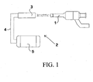
- fig. 1 is an operation diagram of the device according to this invention.
- fig. 2 is a cross-section view of the optical-fibre probe of this invention.
- fig. 3 is a diagram, showing the spectrum or the radiation reflected by the fuel found on the injector head.
- Fig. 1 shows injector 1 which is to be checked.
- the check is run by means of detection device 2 according to the present invention.
- Device 2 comprises an optical-fibre probe 3, connected by cables 4 to a spectrometer 5, which can advantageously be a spectrophotometer.
- probe 3 comprises optical fibres 6 for transmitting a radiation from probe 3 to injector 1 and optical fibres 7 for collecting the reflected radiation.
- injector 1 is brought opposite device 2, aligning it with probe 3.
- probe 3 radiates the surface of injector 1.
- the presence of liquid, possibly blown-by from injector 1, affects radiation reflection, by varying the intensity of the reflected radiation, the wavelength being equal. For the sake of analysis simplicity, ultraviolet radiation is preferred.
- Optical fibres 7 collect the reflected radiation and, through cables 4, transmit it to spectrophotometer 5.
- the present invention allows to achieve the following advantages.
- a remarkable mechanical simplicity since it is possible to operate at set point pressure, or at an only slightly higher pressure, to heighten leaks, not requiring any mechanical device downstream of the injector.
- Remarkable reliability is achieved, since this is an indirect measurement with no risk of breakage or failure, apart from the regular replacement of the (long-lasting) UV lamp.
- the technique provided by the present invention is extremely quick, reducing by up to two or three times the time currently required.
- the device according to the present invention is highly sensitive, being able to detect leaks in the order of 0,1 mm 3 /min. Further improvements may be obtained by using a larger number of optical fibres or more sensitive spectrophotometers.
Landscapes
- Engineering & Computer Science (AREA)
- Chemical & Material Sciences (AREA)
- Combustion & Propulsion (AREA)
- Mechanical Engineering (AREA)
- General Engineering & Computer Science (AREA)
- Investigating Or Analysing Materials By Optical Means (AREA)
- Ignition Installations For Internal Combustion Engines (AREA)
Abstract
Description
- The present invention relates to a device for the detection of fuel leaks in internal combustion engines, such as controlled ignition engines or diesel engines.
- In modern injectors for automotive use, and in particular in those employing direct petrol injection, known as GDI, it is particularly important to guarantee that fuel leaks in a closed valve condition are really minimal, since - due to the nature of the Otto cycle - should blow-by occur with the engine turned off, upon the subsequent starting of the engine, self-ignition may occur in the cylinder where the malfunctioning injector operates. These self-ignitions may cause potentially serious damage, such as crankshaft or compression ring breakage.
- GDI injectors are particularly prone to this problem, since they work at fuel pressures in the order of 200 bar. Thereby, the fuel remains stored in significant amounts in the manifold which feeds the injectors with these pressures, even in the presence of a turned-off engine. An optimal blow-by value is believed to be one below 0,1 mm3/min of petrol.
- These very low values, as can be understood, cannot be obtained by the conventional technique, consisting in testing air blow-by and in experimentally correlating it to that of fuel. Even more advanced techniques, such as vacuum tests, using helium as a marker, have proven to be insufficiently reliable, since also small residual traces of liquids can affect results.
- A technique was hence devised, to check fuel at set point pressure, measuring blow-by by the pressure increase being generated in a small sealed chamber coupled with the injector nose. This method is described in detail in
DE-C2-19 809 926 . Also this system has, however, some major drawbacks. Its reliability is seriously impaired by the delicacy and complexity of some of its mechanical components, for example gaskets, which also call for frequent maintenance. The method implies remarkably-long checking times, whereas checks in automatic high-baud-rate manufacturing systems require an ever shorter time. Moreover, said method has extremely high overall costs and is close to the limits of technically achievable sensitivity, leaving no room for further lowering of the blow-by acceptance threshold. - Such drawbacks are brilliantly solved by the present invention, which refers to a device for blow-by detection, characterised in that it comprises an optical-fibre probe which irradiates the end portion of the injector. Preferably, radiance occurs at ultraviolet (UV) wavelength.
- This invention will now be described in greater detail, with reference to the accompanying drawings, wherein
- fig. 1 is an operation diagram of the device according to this invention;
- fig. 2 is a cross-section view of the optical-fibre probe of this invention; and
- fig. 3 is a diagram, showing the spectrum or the radiation reflected by the fuel found on the injector head.
- Fig. 1 shows injector 1 which is to be checked. The check is run by means of
detection device 2 according to the present invention.Device 2 comprises an optical-fibre probe 3, connected bycables 4 to aspectrometer 5, which can advantageously be a spectrophotometer. - As can be seen in fig. 2,
probe 3 comprisesoptical fibres 6 for transmitting a radiation fromprobe 3 to injector 1 andoptical fibres 7 for collecting the reflected radiation. - During operation, injector 1 is brought
opposite device 2, aligning it withprobe 3. Throughoptical fibres 6,probe 3 radiates the surface of injector 1. The presence of liquid, possibly blown-by from injector 1, affects radiation reflection, by varying the intensity of the reflected radiation, the wavelength being equal. For the sake of analysis simplicity, ultraviolet radiation is preferred. -
Optical fibres 7 collect the reflected radiation and, throughcables 4, transmit it tospectrophotometer 5. - As can be seen in fig. 3, depending on the wavelength radiated on the surface of injector 1, an intensity reaction curve is obtained. Each curve is characteristic of the amount of fuel blown by from injector 1. In order to then return to the actually blown-by amount of fuel, a calibration model is resorted to, obtained by calibration with a known amount of fuel. Various algorithms exist which may be used for calibration; PLS (partial least squares) chemometric methods have proven to be particularly suitable.
- The present invention allows to achieve the following advantages. A remarkable mechanical simplicity, since it is possible to operate at set point pressure, or at an only slightly higher pressure, to heighten leaks, not requiring any mechanical device downstream of the injector. Remarkable reliability is achieved, since this is an indirect measurement with no risk of breakage or failure, apart from the regular replacement of the (long-lasting) UV lamp. Moreover, the technique provided by the present invention is extremely quick, reducing by up to two or three times the time currently required. Finally, the device according to the present invention is highly sensitive, being able to detect leaks in the order of 0,1 mm3/min. Further improvements may be obtained by using a larger number of optical fibres or more sensitive spectrophotometers.
Claims (8)
- Device (2) for the detection of blow-by in injectors (1) of internal combustion engines, characterised in that it comprises a probe (3) employing optical fibres (6, 7) which irradiates the end portion of the injector (1).
- Device (2) as claimed in claim 1), characterised in that radiance occurs at UV wavelength.
- Device (2) as claimed in claim 1) or 2), characterised in that said probe (3) is connected through cables (4) to a spectrometer (5).
- Device (2) as claimed in claim 3), characterised in that said spectrometer is a spectrophotometer (5).
- Device (2) as claimed in any one of the previous claims, characterised in that the probe (3) comprises optical fibres (6) to transmit a radiation from the probe (3) to the injector (1) and optical fibres (7) for collecting the reflected radiation.
- Device as claimed in any previous claim, characterised in that, in order to trace the actually blown-by amount of fuel, a calibration model is resorted to for correlating the spectrum of the reflected radiation to the actually blown-by amount of fuel.
- Device as claimed in claim 6), characterised in that the calibration model is obtained through a PLS (partial least squares) algorithm.
- Method for the detection of blow-by in injectors (1) of internal combustion engines, characterised in that it provides the following steps:a) irradiating the surface of the injector (1) with a radiation having known wavelength and intensity;b) collecting the reflected radiation;c) assessing the intensity of the reflected radiation at one or more pre-defined wavelengths; andd) calculating blow-by extent by means of a calibration mode
Applications Claiming Priority (1)
| Application Number | Priority Date | Filing Date | Title |
|---|---|---|---|
| IT000015A ITAN20050015A1 (en) | 2005-03-31 | 2005-03-31 | DEVICE FOR DETECTING FUEL LEAKS IN INTERNAL COMBUSTION ENGINES |
Publications (2)
| Publication Number | Publication Date |
|---|---|
| EP1710430A2 true EP1710430A2 (en) | 2006-10-11 |
| EP1710430A3 EP1710430A3 (en) | 2006-12-13 |
Family
ID=36607323
Family Applications (1)
| Application Number | Title | Priority Date | Filing Date |
|---|---|---|---|
| EP06111473A Withdrawn EP1710430A3 (en) | 2005-03-31 | 2006-03-21 | Device for the detection of fuel leaks in internal combustion engines |
Country Status (2)
| Country | Link |
|---|---|
| EP (1) | EP1710430A3 (en) |
| IT (1) | ITAN20050015A1 (en) |
Family Cites Families (7)
| Publication number | Priority date | Publication date | Assignee | Title |
|---|---|---|---|---|
| JPS5981530A (en) * | 1982-11-01 | 1984-05-11 | Furukawa Electric Co Ltd:The | Optical fiber liquid leakage detector |
| US5058420A (en) * | 1990-04-20 | 1991-10-22 | Hughes Aircraft Company | Fiber optic liquid leak detector |
| DE19809926C2 (en) * | 1998-03-07 | 2002-08-29 | Sonplas Gmbh Planung Montage U | Procedure for checking and measuring valve leakage |
| DE19838749A1 (en) * | 1998-08-26 | 2000-03-02 | Volkswagen Ag | Leakage rate detection method for internal combustion engine fuel injection valve, e.g. for vehicle diesel engine, evaluates hydrocarbon concentration in fuel stream fed through test body on application of given pressure characteristic |
| DE10031203C2 (en) * | 2000-06-27 | 2002-06-27 | Siemens Ag | Method and device for leak testing of injection valves |
| JP4366840B2 (en) * | 2000-07-06 | 2009-11-18 | 豊和工業株式会社 | Oil leak warning device for garbage truck |
| JP2006003143A (en) * | 2004-06-16 | 2006-01-05 | Shoseki Engineering & Construction Co Ltd | Detection device for petroleum product using optical fiber |
-
2005
- 2005-03-31 IT IT000015A patent/ITAN20050015A1/en unknown
-
2006
- 2006-03-21 EP EP06111473A patent/EP1710430A3/en not_active Withdrawn
Also Published As
| Publication number | Publication date |
|---|---|
| ITAN20050015A1 (en) | 2006-10-01 |
| EP1710430A3 (en) | 2006-12-13 |
Similar Documents
| Publication | Publication Date | Title |
|---|---|---|
| CN101498267B (en) | Test method for ignition fluid injectors | |
| US8746050B2 (en) | Fuel injection feedback system and method | |
| US9932910B2 (en) | Natural gas quality sensor and method for using the same | |
| US9000374B2 (en) | EGR distribution and fluctuation probe based on CO2 measurements | |
| US8205491B2 (en) | Method and system of testing a fuel injector | |
| US5569841A (en) | Cylinder combustion gas leakage testing | |
| GB2471893A (en) | Detecting misfiring in an i.c. engine using in-cylinder pressure measurements | |
| US20160265452A1 (en) | Method and system for laser pressure transducer | |
| AKIMOTO et al. | Development of pattern recognition knock detection system using short-time Fourier transform | |
| Gupta et al. | On use of CO2∗ chemiluminescence for combustion metrics in natural gas fired reciprocating engines | |
| JPH07505694A (en) | Device for detecting engine parameters of internal combustion engines | |
| EP1710430A2 (en) | Device for the detection of fuel leaks in internal combustion engines | |
| Wermuth et al. | Absorption and fluorescence data of acetone, 3-pentanone, biacetyl, and toluene at engine-specific combinations of temperature and pressure | |
| CN112945935A (en) | Spray local equivalence ratio measuring system and method based on laser-induced breakdown spectroscopy | |
| JPH07508582A (en) | Light emitting state detection device for internal combustion engine, engine operating method and temperature detection method | |
| CN101243305B (en) | Method for determining the position of a valve of an internal combustion engine | |
| JP7221857B2 (en) | Anomaly detection device and anomaly detection method | |
| US5271265A (en) | Process and device for sensing and evaluating knocking combustion during operation of an internal combustion engine | |
| KR20220099682A (en) | Inspection device for fuel injector and inspection method thereof | |
| CN115199440A (en) | Optical ignition diagnosis device and method for liquid rocket engine | |
| CN115979506B (en) | Device and method for measuring intake negative pressure in engine cylinder | |
| JP4493075B2 (en) | Gas concentration detection device for internal combustion engine | |
| JP2003014640A (en) | Engine fuel concentration measurement device | |
| Kakuho et al. | Simultaneous measurement of in-cylinder temperature and residual gas concentration in the vicinity of the spark plug by wavelength modulation infrared absorption | |
| KR0182102B1 (en) | Stress measuring apparatus and method of bridge in valve port |
Legal Events
| Date | Code | Title | Description |
|---|---|---|---|
| PUAI | Public reference made under article 153(3) epc to a published international application that has entered the european phase |
Free format text: ORIGINAL CODE: 0009012 |
|
| AK | Designated contracting states |
Kind code of ref document: A2 Designated state(s): AT BE BG CH CY CZ DE DK EE ES FI FR GB GR HU IE IS IT LI LT LU LV MC NL PL PT RO SE SI SK TR |
|
| AX | Request for extension of the european patent |
Extension state: AL BA HR MK YU |
|
| PUAL | Search report despatched |
Free format text: ORIGINAL CODE: 0009013 |
|
| AK | Designated contracting states |
Kind code of ref document: A3 Designated state(s): AT BE BG CH CY CZ DE DK EE ES FI FR GB GR HU IE IS IT LI LT LU LV MC NL PL PT RO SE SI SK TR |
|
| AX | Request for extension of the european patent |
Extension state: AL BA HR MK YU |
|
| RIC1 | Information provided on ipc code assigned before grant |
Ipc: G01M 3/28 20060101ALI20061109BHEP Ipc: G01M 3/02 20060101ALI20061109BHEP Ipc: F02M 65/00 20060101AFI20060704BHEP |
|
| AKX | Designation fees paid | ||
| STAA | Information on the status of an ep patent application or granted ep patent |
Free format text: STATUS: THE APPLICATION IS DEEMED TO BE WITHDRAWN |
|
| 18D | Application deemed to be withdrawn |
Effective date: 20070614 |
|
| REG | Reference to a national code |
Ref country code: DE Ref legal event code: 8566 |