EP1710112A1 - Utility vehicle and hood - Google Patents
Utility vehicle and hood Download PDFInfo
- Publication number
- EP1710112A1 EP1710112A1 EP06110596A EP06110596A EP1710112A1 EP 1710112 A1 EP1710112 A1 EP 1710112A1 EP 06110596 A EP06110596 A EP 06110596A EP 06110596 A EP06110596 A EP 06110596A EP 1710112 A1 EP1710112 A1 EP 1710112A1
- Authority
- EP
- European Patent Office
- Prior art keywords
- hood
- air
- radiator
- air intake
- oil cooler
- Prior art date
- Legal status (The legal status is an assumption and is not a legal conclusion. Google has not performed a legal analysis and makes no representation as to the accuracy of the status listed.)
- Granted
Links
- 244000025254 Cannabis sativa Species 0.000 claims abstract description 23
- 238000002485 combustion reaction Methods 0.000 claims abstract description 6
- 230000003247 decreasing effect Effects 0.000 claims abstract 2
- 239000002991 molded plastic Substances 0.000 claims description 3
- 238000001816 cooling Methods 0.000 description 12
- 239000002826 coolant Substances 0.000 description 5
- 238000001175 rotational moulding Methods 0.000 description 3
- 229910000831 Steel Inorganic materials 0.000 description 2
- 230000001010 compromised effect Effects 0.000 description 2
- 239000000428 dust Substances 0.000 description 2
- 239000004033 plastic Substances 0.000 description 2
- 239000010959 steel Substances 0.000 description 2
- 238000010438 heat treatment Methods 0.000 description 1
- 230000003993 interaction Effects 0.000 description 1
- 239000007788 liquid Substances 0.000 description 1
- 230000004048 modification Effects 0.000 description 1
- 238000012986 modification Methods 0.000 description 1
- 238000005192 partition Methods 0.000 description 1
- 239000000088 plastic resin Substances 0.000 description 1
- 238000005303 weighing Methods 0.000 description 1
Images


Classifications
-
- F—MECHANICAL ENGINEERING; LIGHTING; HEATING; WEAPONS; BLASTING
- F01—MACHINES OR ENGINES IN GENERAL; ENGINE PLANTS IN GENERAL; STEAM ENGINES
- F01P—COOLING OF MACHINES OR ENGINES IN GENERAL; COOLING OF INTERNAL-COMBUSTION ENGINES
- F01P11/00—Component parts, details, or accessories not provided for in, or of interest apart from, groups F01P1/00 - F01P9/00
- F01P11/10—Guiding or ducting cooling-air, to, or from, liquid-to-air heat exchangers
-
- F—MECHANICAL ENGINEERING; LIGHTING; HEATING; WEAPONS; BLASTING
- F01—MACHINES OR ENGINES IN GENERAL; ENGINE PLANTS IN GENERAL; STEAM ENGINES
- F01P—COOLING OF MACHINES OR ENGINES IN GENERAL; COOLING OF INTERNAL-COMBUSTION ENGINES
- F01P7/00—Controlling of coolant flow
- F01P7/02—Controlling of coolant flow the coolant being cooling-air
- F01P7/10—Controlling of coolant flow the coolant being cooling-air by throttling amount of air flowing through liquid-to-air heat exchangers
-
- B—PERFORMING OPERATIONS; TRANSPORTING
- B60—VEHICLES IN GENERAL
- B60Y—INDEXING SCHEME RELATING TO ASPECTS CROSS-CUTTING VEHICLE TECHNOLOGY
- B60Y2200/00—Type of vehicle
- B60Y2200/20—Off-Road Vehicles
- B60Y2200/22—Agricultural vehicles
- B60Y2200/223—Ridable lawn mowers
-
- F—MECHANICAL ENGINEERING; LIGHTING; HEATING; WEAPONS; BLASTING
- F01—MACHINES OR ENGINES IN GENERAL; ENGINE PLANTS IN GENERAL; STEAM ENGINES
- F01P—COOLING OF MACHINES OR ENGINES IN GENERAL; COOLING OF INTERNAL-COMBUSTION ENGINES
- F01P3/00—Liquid cooling
- F01P3/18—Arrangements or mounting of liquid-to-air heat-exchangers
- F01P2003/187—Arrangements or mounting of liquid-to-air heat-exchangers arranged in series
-
- F—MECHANICAL ENGINEERING; LIGHTING; HEATING; WEAPONS; BLASTING
- F01—MACHINES OR ENGINES IN GENERAL; ENGINE PLANTS IN GENERAL; STEAM ENGINES
- F01P—COOLING OF MACHINES OR ENGINES IN GENERAL; COOLING OF INTERNAL-COMBUSTION ENGINES
- F01P3/00—Liquid cooling
- F01P3/18—Arrangements or mounting of liquid-to-air heat-exchangers
Definitions
- This invention relates to a utility vehicle, preferably a grass mowing machine, comprising a hood covering an internal combustion engine having a radiator with an air inlet side and a fan to draw air through the radiator; the hood having a top surface with a first end and a second end, the first end positioned closer to the radiator and fan than the second end; a plurality of exterior air intake openings in the top surface of the hood and a hood of such a utility vehicle.
- hoods or shrouds on large grass mowing machines, tractors and similar off-road or agricultural vehicles typically enclose an engine, cooling system, and other vehicle components.
- Such vehicles commonly utilize liquid cooled internal combustion engines which generate heat during their operation.
- Liquid-cooled engines employ pressurized coolant circulated through the engine to absorb heat.
- the heated coolant is subsequently passed through a heat exchanger such as a radiator to dissipate heat from the coolant to the atmosphere, after which the coolant is recirculated to the engine for further engine cooling.
- a heat exchanger such as a radiator to dissipate heat from the coolant to the atmosphere, after which the coolant is recirculated to the engine for further engine cooling.
- air flows through the heat exchanger to absorb heat and carry it out into the atmosphere.
- Air is commonly drawn or propelled through the radiator and/or oil cooler by use of a fan.
- US-A-6,202,777 shows cooling system assembly is provided for an off-road vehicle having an engine surrounded at least in part by an engine enclosure.
- the cooling system assembly includes a heat exchanger having an air intake face.
- the heat exchanger is coupled to the engine for cooling the engine.
- the engine enclosure includes an end face lying substantially in a plane disposed substantially perpendicular to a longitudinal axis of the vehicle and first and second side faces, each of said first and second side faces lying substantially in a plane disposed substantially parallel to the longitudinal axis of the vehicle.
- the enclosure has an air intake located at least partially on the end face and at least one of the first and second side faces.
- An inner wall forms a baffle on at least one of the faces for directing air from the air intake to the heat exchanger air intake face.
- the capacity of a cooling system in such a vehicle depends on many factors including the velocity and volume of air flowing through the heat exchanger, as well as the distribution of the air flow over the available heat exchange surface of the radiator and/or oil cooler.
- the surface area of the air intake on the hood of such a vehicle may be as large as six square feet or more. These vehicles may be used for cutting grass or other vegetation, so the air used to cool the radiator is frequently contaminated with dust, grass clippings and similar debris.
- such vehicles will include grilles or screens on their hoods to reduce debris present in the cooling air while allowing the air to pass into the area enclosed by the hood to cool the engine by interaction with the radiator and/or oil cooler. However, debris may accumulate on and around the outer surface of the grille or screen, clogging the intake and restricting the air flow.
- Air velocity at some areas of a grille or screen may be substantially higher than the velocity at other areas.
- areas of the grille or screen that are relatively close to the air inlet side of the radiator and/or oil cooler may have air flow velocities several times higher than areas further away from the air inlet side of the radiator and/or oil cooler.
- the air velocity may be as high as 20,000 mm/second at air intake openings near the air inlet side of the radiator and/or oil cooler, and less than 1000 mm/second at air intake openings furthest from the radiator and/or oil cooler. If enough debris accumulates to block the portion of the grille or screen with the highest air velocity, the effective air intake area is reduced. As a result, the vehicle's engine may not be cooled as efficiently or quietly.
- Hoods or shrouds for large grass mowing machines, tractors and similar vehicles may be made from a combination of sheet steel, plastic and perforated screens or grilles.
- the hood for the 1600 Turbo Wide-Area Mower manufactured by Deere & Company of Moline, Illinois includes sheet steel panels and a perforated screen providing an intake area that draws air from the top and sides of the machine over the hood.
- Some vehicles also may include a baffle to prevent the air supply from being heated by the engine as the air is drawn to and passed through the radiator and/or oil cooler.
- Some hoods may be relatively heavy (weighing as much as 200 pounds or more), expensive to build and assemble, and provide inefficient air flow.
- a hood or shroud for a large grass mowing machine, tractor or similar vehicle is needed that has reduced weight and cost.
- a hood or shroud is needed for such a vehicle that provides improved air flow efficiency.
- a hood or shroud is needed that can provide a supply of cooling air to an engine for a large grass mowing machine, tractor, or similar vehicle without the flow being interrupted or compromised due to blockages of the grille or screen caused by dust, grass clippings or similar debris.
- An air intake for a hood on a large grass mowing machine, tractor or similar vehicle is needed that can provide more uniform and even air flow velocity across different areas of a grille or screen.
- a hood for a large grass mowing machine, tractor or similar vehicle is needed that includes an air intake that provides more uniform air flow while minimizing engine noise escaping from the engine compartment.
- the object to be met with the invention is to comply with any or all of these needs.
- a hood hinged to the rear of a grass mowing machine may include a rotational molded plastic shell having a top surface, left and right side panels, and first and second ends.
- the first end of the hood may be adjacent the rear of the grass mowing machine, and an integral air duct below the top surface of the hood directs cooling air to the air inlet side of the radiator and/or oil cooler for engine cooling.
- the top of the hood has a number of air intake openings into the integral air duct.
- the air intake openings are dimensioned to provide more uniform air flow velocities through each opening, so that debris does not clog the screens or grilles over the openings.
- each of the air intake openings may decrease in area from the second end to the first end of the hood.
- the hood may cover an internal combustion engine on the rear of a grass mowing machine.
- the hood has a top surface with a plurality of air intake openings recessed below the top surface, and an integral air duct.
- the integral air duct extends over the engine between the air intake openings and an air inlet side of the radiator and/or oil cooler adjacent the rear of the grass mowing machine.
- the air intake openings closest to the air inlet side of the radiator and/or oil cooler are dimensioned to limit the air intake velocity and prevent buildup of debris on screens or grilles over the openings.
- hood reduced weight and cost compared to conventional hoods used on large grass mowing machines.
- the hood provides improved air flow efficiency, and provides a supply of cooling air to the engine without the flow being interrupted or compromised due to blockages of the grille or screen.
- the hood includes air intake openings that can provide more uniform and even air flow velocity across different areas of a grille or screen. The hood provides more uniform air flow while minimizing engine noise escaping from the engine compartment.
- hood 10 may enclose an engine supported on a vehicle frame at or near the rear of a large grass mowing machine or utility vehicle 11.
- the hood may be located behind the operator's station.
- the engine may be an internal combustion engine with a cooling system including radiator and/or oil cooler 12 , fan 13 and fan shroud 14 facing toward the rear of the vehicle.
- the hood may be connected by hinge 49 to the rear of the frame of the grass mowing machine for opening and servicing the engine.
- hood 10 may be a rotational molded plastic shell 15 with a first end 16 and a second end 17, an outwardly convex, rounded, or sloped top surface 18, and left and right side surfaces 19 and 20.
- Rotational molding also known as rotomolding, involves loading a plastic resin into a mold that is heated as it is rotated slowly on both a vertical axis and a horizontal axis. The simultaneous heating and rotation distributes the plastic on the inner surfaces of the mold and fuses it into the desired shape.
- Hoods manufactured by rotational molding according to a preferred embodiment of the invention have approximately 20% reduction in weight and reduced cost compared to conventional hoods of the same or similar size for large grass mowing machines.
- hood 10 may have an integral air duct 21 under the top surface and extending generally horizontally between the air intakes and air inlet side 23 of radiator and/or oil cooler 12. Integral air duct 21 may be formed between the top surface 18 of the hood and internal baffle 22 which may shield and partition or separate the integral air duct from the engine. Additionally, the hood and radiator may define an air duct 50 extending generally vertically between the first end 16 of the hood and the air inlet side 23 of radiator and/or oil cooler 12. Air ducts 21, 50 may direct air from the air intakes rearwardly toward the air inlet side 23 of radiator and/or oil cooler 12, where fan 13 may draw the intake air into and through the radiator and/or oil cooler.
- internal baffle 22 may provide a generally horizontal surface spaced about 2,54 cm (1 inch) to about 15,25 cm (6 inches) below the top surface of the hood.
- the top surface 18 of the hood and the internal baffle 22 together define integral air duct 21 which may extend over the engine toward the air inlet side 23 of the radiator adjacent the rear of a grass mowing machine.
- the first end of the hood and the radiator and/or oil cooler together define air duct 50 which may extend downwardly from integral air duct 21.
- an internal baffle (not shown) may be included within air duct 50 to direct or divert some of the air to either the radiator or oil cooler.
- hood 10 may have a plurality of separate perforated screens or grilles that are positioned on or near the top surface of the hood.
- the screens or grilles allow air flow from the outside to be pulled through integral air duct 21 between the top surface 18 of the hood and internal baffle 22.
- Each screen or grille may be placed over one or multiple air intakes.
- each screen or grille may be placed over as many as four or more separate air intakes.
- at least some of the air intakes may have areas substantially smaller than the screens, and the air intake dimensions are configured to reduce or minimize congestion of grass clippings and other debris on the screen or grille.
- screens or grilles 24-26 may cover air intakes on the top surface of the hood.
- Screens or grilles 27-28 may cover air intakes on the left and right sides of the hood.
- the hood includes a plurality of exterior air intake openings recessed about 1,27 cm (1 ⁇ 2 inch) to about 5,08 cm (2 inches) from the top and side surfaces of the hood.
- the exterior air intake openings may be at or project from the top and side surfaces of the hood.
- the exterior air intake openings are dimensioned and positioned to optimize air flow into air ducts 21, 50 to cool the engine.
- the exterior air intake openings may be dimensioned and positioned to reduce the air flow velocity at openings that are closest to the air inlet side of the radiator.
- the dimensions provide more uniform air flow over all openings. For example, the air flow velocity at each opening may be not more than twice the air flow velocity at any other opening.
- the air intake openings closest to the air inlet side of the radiator and/or oil cooler may be dimensioned to have smaller areas than openings further from the air inlet side of the radiator and/or oil cooler. As a result of the reduced or stepped dimensions of the exterior air intake openings, clogging of the screens or grilles may be minimized or substantially reduced.
- the exterior air intake openings may have smaller areas than the screens or grilles. Additionally, the exterior air intake openings in the top surface of the hood may be reduced or stepped down in surface area between the second end of the hood; i.e., furthest from the air inlet side of the radiator and/or oil cooler; and the first end of the hood; i.e., nearest the air inlet side of the radiator and/or oil cooler.
- the top air intake openings closer to the first end of the hood have at least one dimension that is smaller than the openings near the second end of the hood.
- the smallest openings may be located in the top surface near the first end of the hood, i.e., closest to the air inlet side of the radiator and/or oil cooler, and the largest openings may be in the top surface near the second end of the hood, i.e., furthest from the air inlet side of the radiator and/or oil cooler.
- top air intake openings 29-30 near the first end of the hood each may have an area of less than about 32,258 cm 2 (5 square inches).
- Top air intake openings 31-32 each may have an area of less than about 64,516 cm 2 (10 square inches).
- Top air intake openings 33-34 each may have an area of less than about 96,774 cm 2 (15 square inches).
- Top air intake openings 35-36 each may have an area of less than about 129,032 cm 2 (20 square inches).
- Top air intake openings 37-38 nearest the second end of the hood each may have an area of less than about 193,548 cm 2 (50 square inches).
- the exterior air intake openings in the left and right sides of the hood may be reduced or stepped down in surface area between the second end of the hood; i.e., furthest from the air inlet side 23 of the radiator and/or oil cooler; and the first end of the hood; i.e., closest to the air inlet side 23 of the radiator and/or oil cooler.
- Side air intake openings closer to the first end of the hood may have at least one dimension that is smaller than the openings near the second end of the hood.
- the smallest openings may be located in the side surface near the first end of the hood, i.e., closest to the air inlet side of the radiator and/or oil cooler, and the largest openings may be in the side surface near the second end of the hood, i.e., furthest from the air inlet side of the radiator and/or oil cooler.
- side air intake openings 39-40 near the first end of the hood each may have an area of less than about 32,258 cm 2 (5 square inches).
- Side air intake openings 41-42 each may have an area of less than about 64,516 cm 2 (10 square inches).
- Side air intake openings 43-44 each may have an area of less than about 96,774 cm 2 (15 square inches).
- Side air intake openings 45-46 near the second end of the hood each may have an area of less than about 129,032 cm 2 (20 square inches).
- the top surface of the hood may include ribs 47 between the screens or grilles, and support structures 48 under the screens or grilles. Additional panels 51, 52 may be attached to the left and right side surfaces 19, 20.
Landscapes
- Engineering & Computer Science (AREA)
- Chemical & Material Sciences (AREA)
- Combustion & Propulsion (AREA)
- Mechanical Engineering (AREA)
- General Engineering & Computer Science (AREA)
- Cooling, Air Intake And Gas Exhaust, And Fuel Tank Arrangements In Propulsion Units (AREA)
Abstract
Description
- This invention relates to a utility vehicle, preferably a grass mowing machine, comprising a hood covering an internal combustion engine having a radiator with an air inlet side and a fan to draw air through the radiator; the hood having a top surface with a first end and a second end, the first end positioned closer to the radiator and fan than the second end; a plurality of exterior air intake openings in the top surface of the hood and a hood of such a utility vehicle.
- Conventional hoods or shrouds on large grass mowing machines, tractors and similar off-road or agricultural vehicles typically enclose an engine, cooling system, and other vehicle components. Such vehicles commonly utilize liquid cooled internal combustion engines which generate heat during their operation. Liquid-cooled engines employ pressurized coolant circulated through the engine to absorb heat. The heated coolant is subsequently passed through a heat exchanger such as a radiator to dissipate heat from the coolant to the atmosphere, after which the coolant is recirculated to the engine for further engine cooling. As the coolant is passed through the heat exchanger, air flows through the heat exchanger to absorb heat and carry it out into the atmosphere. Air is commonly drawn or propelled through the radiator and/or oil cooler by use of a fan.
-
US-A-6,202,777 shows cooling system assembly is provided for an off-road vehicle having an engine surrounded at least in part by an engine enclosure. The cooling system assembly includes a heat exchanger having an air intake face. The heat exchanger is coupled to the engine for cooling the engine. The engine enclosure includes an end face lying substantially in a plane disposed substantially perpendicular to a longitudinal axis of the vehicle and first and second side faces, each of said first and second side faces lying substantially in a plane disposed substantially parallel to the longitudinal axis of the vehicle. The enclosure has an air intake located at least partially on the end face and at least one of the first and second side faces. An inner wall forms a baffle on at least one of the faces for directing air from the air intake to the heat exchanger air intake face. - The capacity of a cooling system in such a vehicle depends on many factors including the velocity and volume of air flowing through the heat exchanger, as well as the distribution of the air flow over the available heat exchange surface of the radiator and/or oil cooler. The surface area of the air intake on the hood of such a vehicle may be as large as six square feet or more. These vehicles may be used for cutting grass or other vegetation, so the air used to cool the radiator is frequently contaminated with dust, grass clippings and similar debris. Typically, such vehicles will include grilles or screens on their hoods to reduce debris present in the cooling air while allowing the air to pass into the area enclosed by the hood to cool the engine by interaction with the radiator and/or oil cooler. However, debris may accumulate on and around the outer surface of the grille or screen, clogging the intake and restricting the air flow.
- In these vehicles, debris tends to build up rapidly and accumulate first on those areas of a grille or screen where air flows at the highest velocity. Air velocity at some areas of a grille or screen may be substantially higher than the velocity at other areas. For a grille or screen on or above the top surface of a vehicle hood, areas of the grille or screen that are relatively close to the air inlet side of the radiator and/or oil cooler may have air flow velocities several times higher than areas further away from the air inlet side of the radiator and/or oil cooler. For example, the air velocity may be as high as 20,000 mm/second at air intake openings near the air inlet side of the radiator and/or oil cooler, and less than 1000 mm/second at air intake openings furthest from the radiator and/or oil cooler. If enough debris accumulates to block the portion of the grille or screen with the highest air velocity, the effective air intake area is reduced. As a result, the vehicle's engine may not be cooled as efficiently or quietly.
- Hoods or shrouds for large grass mowing machines, tractors and similar vehicles may be made from a combination of sheet steel, plastic and perforated screens or grilles. For example, the hood for the 1600 Turbo Wide-Area Mower manufactured by Deere & Company of Moline, Illinois includes sheet steel panels and a perforated screen providing an intake area that draws air from the top and sides of the machine over the hood. Some vehicles also may include a baffle to prevent the air supply from being heated by the engine as the air is drawn to and passed through the radiator and/or oil cooler. Some hoods may be relatively heavy (weighing as much as 200 pounds or more), expensive to build and assemble, and provide inefficient air flow.
- A hood or shroud for a large grass mowing machine, tractor or similar vehicle is needed that has reduced weight and cost. A hood or shroud is needed for such a vehicle that provides improved air flow efficiency. A hood or shroud is needed that can provide a supply of cooling air to an engine for a large grass mowing machine, tractor, or similar vehicle without the flow being interrupted or compromised due to blockages of the grille or screen caused by dust, grass clippings or similar debris. An air intake for a hood on a large grass mowing machine, tractor or similar vehicle is needed that can provide more uniform and even air flow velocity across different areas of a grille or screen. A hood for a large grass mowing machine, tractor or similar vehicle is needed that includes an air intake that provides more uniform air flow while minimizing engine noise escaping from the engine compartment.
- The object to be met with the invention is to comply with any or all of these needs.
- This object is met according to the invention by the teaching of
claims 1 or 10 respectively, while features developing the solution in an advantageous manner are set forth in the further claims. - A hood hinged to the rear of a grass mowing machine may include a rotational molded plastic shell having a top surface, left and right side panels, and first and second ends. The first end of the hood may be adjacent the rear of the grass mowing machine, and an integral air duct below the top surface of the hood directs cooling air to the air inlet side of the radiator and/or oil cooler for engine cooling. The top of the hood has a number of air intake openings into the integral air duct. The air intake openings are dimensioned to provide more uniform air flow velocities through each opening, so that debris does not clog the screens or grilles over the openings. To provide more uniform air flow, each of the air intake openings may decrease in area from the second end to the first end of the hood.
- The hood may cover an internal combustion engine on the rear of a grass mowing machine. The hood has a top surface with a plurality of air intake openings recessed below the top surface, and an integral air duct. The integral air duct extends over the engine between the air intake openings and an air inlet side of the radiator and/or oil cooler adjacent the rear of the grass mowing machine. The air intake openings closest to the air inlet side of the radiator and/or oil cooler are dimensioned to limit the air intake velocity and prevent buildup of debris on screens or grilles over the openings.
- Such hood reduced weight and cost compared to conventional hoods used on large grass mowing machines. The hood provides improved air flow efficiency, and provides a supply of cooling air to the engine without the flow being interrupted or compromised due to blockages of the grille or screen. The hood includes air intake openings that can provide more uniform and even air flow velocity across different areas of a grille or screen. The hood provides more uniform air flow while minimizing engine noise escaping from the engine compartment.
- An embodiment of the invention described below is shown in the drawings, in which:
- Fig. 1
- is a top perspective view of a large grass mowing machine having a hood with an integral air duct according to a first embodiment of the invention.
- Fig. 2
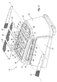
- is an exploded perspective view of a hood with an integral air duct according to a first embodiment of the invention.
- Fig. 3
- is a perspective view, partially in section, of a hood with an integral air duct according to a first embodiment of the invention.
- As shown in Figs. 1-3, in a first embodiment of the invention,
hood 10 may enclose an engine supported on a vehicle frame at or near the rear of a large grass mowing machine orutility vehicle 11. The hood may be located behind the operator's station. The engine may be an internal combustion engine with a cooling system including radiator and/oroil cooler 12 ,fan 13 andfan shroud 14 facing toward the rear of the vehicle. The hood may be connected byhinge 49 to the rear of the frame of the grass mowing machine for opening and servicing the engine. - In one embodiment,
hood 10 may be a rotational moldedplastic shell 15 with afirst end 16 and asecond end 17, an outwardly convex, rounded, or slopedtop surface 18, and left andright side surfaces - In one embodiment,
hood 10 may have anintegral air duct 21 under the top surface and extending generally horizontally between the air intakes andair inlet side 23 of radiator and/oroil cooler 12.Integral air duct 21 may be formed between thetop surface 18 of the hood andinternal baffle 22 which may shield and partition or separate the integral air duct from the engine. Additionally, the hood and radiator may define anair duct 50 extending generally vertically between thefirst end 16 of the hood and theair inlet side 23 of radiator and/oroil cooler 12.Air ducts air inlet side 23 of radiator and/oroil cooler 12, wherefan 13 may draw the intake air into and through the radiator and/or oil cooler. - In one embodiment,
internal baffle 22 may provide a generally horizontal surface spaced about 2,54 cm (1 inch) to about 15,25 cm (6 inches) below the top surface of the hood. Thus, thetop surface 18 of the hood and theinternal baffle 22 together defineintegral air duct 21 which may extend over the engine toward theair inlet side 23 of the radiator adjacent the rear of a grass mowing machine. The first end of the hood and the radiator and/or oil cooler together defineair duct 50 which may extend downwardly fromintegral air duct 21. Optionally, an internal baffle (not shown) may be included withinair duct 50 to direct or divert some of the air to either the radiator or oil cooler. - In one embodiment,
hood 10 may have a plurality of separate perforated screens or grilles that are positioned on or near the top surface of the hood. The screens or grilles allow air flow from the outside to be pulled throughintegral air duct 21 between thetop surface 18 of the hood andinternal baffle 22. Each screen or grille may be placed over one or multiple air intakes. For example, each screen or grille may be placed over as many as four or more separate air intakes. As will be described in more detail below, at least some of the air intakes may have areas substantially smaller than the screens, and the air intake dimensions are configured to reduce or minimize congestion of grass clippings and other debris on the screen or grille. In one embodiment, screens or grilles 24-26 may cover air intakes on the top surface of the hood. Screens or grilles 27-28 may cover air intakes on the left and right sides of the hood. - In one embodiment, the hood includes a plurality of exterior air intake openings recessed about 1,27 cm (½ inch) to about 5,08 cm (2 inches) from the top and side surfaces of the hood. Alternatively, the exterior air intake openings may be at or project from the top and side surfaces of the hood. The exterior air intake openings are dimensioned and positioned to optimize air flow into
air ducts - In one embodiment, at least some of the exterior air intake openings may have smaller areas than the screens or grilles. Additionally, the exterior air intake openings in the top surface of the hood may be reduced or stepped down in surface area between the second end of the hood; i.e., furthest from the air inlet side of the radiator and/or oil cooler; and the first end of the hood; i.e., nearest the air inlet side of the radiator and/or oil cooler. The top air intake openings closer to the first end of the hood have at least one dimension that is smaller than the openings near the second end of the hood. The smallest openings may be located in the top surface near the first end of the hood, i.e., closest to the air inlet side of the radiator and/or oil cooler, and the largest openings may be in the top surface near the second end of the hood, i.e., furthest from the air inlet side of the radiator and/or oil cooler.
- For example, in one embodiment, top air intake openings 29-30 near the first end of the hood each may have an area of less than about 32,258 cm2 (5 square inches). Top air intake openings 31-32 each may have an area of less than about 64,516 cm2 (10 square inches). Top air intake openings 33-34 each may have an area of less than about 96,774 cm2 (15 square inches). Top air intake openings 35-36 each may have an area of less than about 129,032 cm2 (20 square inches). Top air intake openings 37-38 nearest the second end of the hood each may have an area of less than about 193,548 cm2 (50 square inches).
- Similarly, the exterior air intake openings in the left and right sides of the hood may be reduced or stepped down in surface area between the second end of the hood; i.e., furthest from the
air inlet side 23 of the radiator and/or oil cooler; and the first end of the hood; i.e., closest to theair inlet side 23 of the radiator and/or oil cooler. Side air intake openings closer to the first end of the hood may have at least one dimension that is smaller than the openings near the second end of the hood. The smallest openings may be located in the side surface near the first end of the hood, i.e., closest to the air inlet side of the radiator and/or oil cooler, and the largest openings may be in the side surface near the second end of the hood, i.e., furthest from the air inlet side of the radiator and/or oil cooler. - In one embodiment, side air intake openings 39-40 near the first end of the hood each may have an area of less than about 32,258 cm2 (5 square inches). Side air intake openings 41-42 each may have an area of less than about 64,516 cm2 (10 square inches). Side air intake openings 43-44 each may have an area of less than about 96,774 cm2 (15 square inches). Side air intake openings 45-46 near the second end of the hood each may have an area of less than about 129,032 cm2 (20 square inches).
- In one embodiment, the top surface of the hood may include
ribs 47 between the screens or grilles, andsupport structures 48 under the screens or grilles.Additional panels - Having described the preferred embodiment, it will become apparent that various modifications can be made without departing from the scope of the invention as defined in the accompanying claims.
Claims (11)
Applications Claiming Priority (1)
| Application Number | Priority Date | Filing Date | Title |
|---|---|---|---|
| US11/091,458 US7370718B2 (en) | 2005-03-28 | 2005-03-28 | Hood with integral air duct |
Publications (2)
| Publication Number | Publication Date |
|---|---|
| EP1710112A1 true EP1710112A1 (en) | 2006-10-11 |
| EP1710112B1 EP1710112B1 (en) | 2008-08-13 |
Family
ID=36644914
Family Applications (1)
| Application Number | Title | Priority Date | Filing Date |
|---|---|---|---|
| EP06110596A Ceased EP1710112B1 (en) | 2005-03-28 | 2006-03-02 | Utility vehicle and hood |
Country Status (3)
| Country | Link |
|---|---|
| US (1) | US7370718B2 (en) |
| EP (1) | EP1710112B1 (en) |
| DE (1) | DE602006002153D1 (en) |
Families Citing this family (19)
| Publication number | Priority date | Publication date | Assignee | Title |
|---|---|---|---|---|
| JP4847073B2 (en) * | 2005-08-29 | 2011-12-28 | ヤンマー株式会社 | Tractor |
| US20080053746A1 (en) * | 2006-08-30 | 2008-03-06 | Albert Roger W | Noise reduction shroud |
| US8230957B2 (en) * | 2008-01-30 | 2012-07-31 | Deere & Company | Flow-inducing baffle for engine compartment ventilation |
| US20100301638A1 (en) * | 2009-05-29 | 2010-12-02 | Hinshaw Eric J | Integrated Air Intake System |
| USD622295S1 (en) | 2010-01-29 | 2010-08-24 | Briggs & Stratton Corporation | Lawn tractor grill |
| US20110203864A1 (en) * | 2010-02-25 | 2011-08-25 | Briggs & Stratton Corporation | Hood assembly for a lawn tractor with removable cowl |
| USD622292S1 (en) | 2010-03-03 | 2010-08-24 | Briggs & Stratton Corporation | Lawn tractor |
| JP2012091745A (en) * | 2010-10-28 | 2012-05-17 | Hitachi Constr Mach Co Ltd | Transportation vehicle |
| US8418790B2 (en) | 2011-09-20 | 2013-04-16 | Deere & Company | Cooling package baffle or ducting |
| US8453777B2 (en) * | 2011-10-24 | 2013-06-04 | Deere & Company | Cooling fan duct assembly |
| US8783398B2 (en) * | 2012-03-02 | 2014-07-22 | Caterpillar Inc. | Replaceable cooling system compartment door screen insert |
| JP5758338B2 (en) * | 2012-03-29 | 2015-08-05 | 株式会社クボタ | Working machine |
| CA2779475C (en) * | 2012-05-29 | 2015-04-07 | Macdon Industries Ltd. | Windrower tractor with parallel heat exchangers for cooling of engine and associated fluids |
| US8936128B2 (en) * | 2013-02-22 | 2015-01-20 | Komatsu Ltd. | Engine room of a wheel loader |
| EP2947210B1 (en) * | 2015-03-10 | 2018-07-11 | Komatsu Ltd. | Industrial vehicle |
| JP2019116198A (en) * | 2017-12-27 | 2019-07-18 | ヤマハ発動機株式会社 | vehicle |
| US11156160B2 (en) | 2018-06-29 | 2021-10-26 | Cnh Industrial America Llc | Shielding assembly for debris management |
| US11499470B2 (en) | 2020-04-29 | 2022-11-15 | Exmark Manufacturing Company Incorporated | Vehicle with parallel engine cooling systems |
| US12311741B2 (en) * | 2022-09-20 | 2025-05-27 | Cnh Industrial America Llc | Vehicle with debris shield |
Citations (4)
| Publication number | Priority date | Publication date | Assignee | Title |
|---|---|---|---|---|
| DE899909C (en) * | 1951-01-25 | 1953-12-17 | Nordwestdeutscher Fahrzeugbau | Fresh air, especially cooling air, for the rear engine of streamlined motor vehicles |
| US5193636A (en) * | 1990-07-23 | 1993-03-16 | Deere & Company | Hood |
| US5947219A (en) * | 1997-01-16 | 1999-09-07 | Mtd Products Inc. | Air flow structure for use with an associated engine |
| US6167976B1 (en) * | 1998-07-30 | 2001-01-02 | Deere & Company | Engine enclosure |
Family Cites Families (12)
| Publication number | Priority date | Publication date | Assignee | Title |
|---|---|---|---|---|
| US4341277A (en) * | 1980-06-23 | 1982-07-27 | Fiat-Allis Construction Machinery, Inc. | Perforated hood with air scoop |
| US4454926A (en) | 1982-03-08 | 1984-06-19 | International Harvester Co. | Air intake on a tractor engine hood |
| US4606422A (en) * | 1985-03-06 | 1986-08-19 | Deere & Company | Cooling air delivery systems |
| US4771844A (en) * | 1987-02-11 | 1988-09-20 | The Toro Company | Method and apparatus for cooling a prime mover |
| US5199521A (en) * | 1990-07-18 | 1993-04-06 | Kubota Corporation | Lawn mower having passages for engine cooling air |
| JP3053059B2 (en) * | 1994-11-30 | 2000-06-19 | 株式会社クボタ | Work vehicle |
| US5794733A (en) | 1996-08-16 | 1998-08-18 | Volvo Gm Heavy Truck Corporation | Vehicle air intake and method |
| US6202777B1 (en) | 1999-05-21 | 2001-03-20 | Deere & Company | Engine enclosure with cooling air baffle |
| US6823955B2 (en) * | 2001-06-27 | 2004-11-30 | Deere & Company | 360 degree air intake screen |
| US6634448B2 (en) * | 2001-07-20 | 2003-10-21 | Mark Bland | Riding lawn mower with improved radiator system |
| US7458434B2 (en) * | 2004-07-23 | 2008-12-02 | Kubota Corporation | Lawn mower having an engine disposed rearwardly of a driver's seat |
| US7213667B2 (en) * | 2004-10-29 | 2007-05-08 | Deere & Company | Air intake |
-
2005
- 2005-03-28 US US11/091,458 patent/US7370718B2/en not_active Expired - Lifetime
-
2006
- 2006-03-02 EP EP06110596A patent/EP1710112B1/en not_active Ceased
- 2006-03-02 DE DE602006002153T patent/DE602006002153D1/en not_active Expired - Lifetime
Patent Citations (4)
| Publication number | Priority date | Publication date | Assignee | Title |
|---|---|---|---|---|
| DE899909C (en) * | 1951-01-25 | 1953-12-17 | Nordwestdeutscher Fahrzeugbau | Fresh air, especially cooling air, for the rear engine of streamlined motor vehicles |
| US5193636A (en) * | 1990-07-23 | 1993-03-16 | Deere & Company | Hood |
| US5947219A (en) * | 1997-01-16 | 1999-09-07 | Mtd Products Inc. | Air flow structure for use with an associated engine |
| US6167976B1 (en) * | 1998-07-30 | 2001-01-02 | Deere & Company | Engine enclosure |
Also Published As
| Publication number | Publication date |
|---|---|
| EP1710112B1 (en) | 2008-08-13 |
| DE602006002153D1 (en) | 2008-09-25 |
| US7370718B2 (en) | 2008-05-13 |
| US20060213708A1 (en) | 2006-09-28 |
Similar Documents
| Publication | Publication Date | Title |
|---|---|---|
| EP1710112B1 (en) | Utility vehicle and hood | |
| EP1582715A1 (en) | Vehicle Cooling Package | |
| EP2522826B1 (en) | Tractor hood airflow system | |
| CA2242104C (en) | Engine enclosure | |
| US8403089B2 (en) | Use of fan shroud to ventilate engine compartment | |
| US6435264B1 (en) | Cooling system for working vehicle | |
| US6202777B1 (en) | Engine enclosure with cooling air baffle | |
| CA2779475C (en) | Windrower tractor with parallel heat exchangers for cooling of engine and associated fluids | |
| EP1925197B1 (en) | Cooling enclosure | |
| EP1652756B1 (en) | Vehicle Hood | |
| US8875823B2 (en) | Multi-functional cooling system | |
| US5947219A (en) | Air flow structure for use with an associated engine | |
| US6837324B2 (en) | Engine enclosure | |
| AU2004202795A1 (en) | Vertical airflow engine cooling system | |
| AU4510800A (en) | Heating ventilating and air conditioning system for a skid steer loader | |
| US20070051326A1 (en) | Vehicle parallel cooling system | |
| TW201821302A (en) | Motorcycle engine cooling system | |
| US20060266309A1 (en) | Vehicle cooling system | |
| US8418790B2 (en) | Cooling package baffle or ducting | |
| CN108474288A (en) | tractor with cooling system | |
| CN111852699B (en) | Engine air pre-cleaning system | |
| CA2378109A1 (en) | 360 degree air intake screen | |
| JP3425679B2 (en) | Combine cooling system | |
| EP4530108A1 (en) | Agricultural vehicle comprising engine bonnet with aeration grilles | |
| JP3679307B2 (en) | Cooling device for internal combustion engine |
Legal Events
| Date | Code | Title | Description |
|---|---|---|---|
| PUAI | Public reference made under article 153(3) epc to a published international application that has entered the european phase |
Free format text: ORIGINAL CODE: 0009012 |
|
| AK | Designated contracting states |
Kind code of ref document: A1 Designated state(s): AT BE BG CH CY CZ DE DK EE ES FI FR GB GR HU IE IS IT LI LT LU LV MC NL PL PT RO SE SI SK TR |
|
| AX | Request for extension of the european patent |
Extension state: AL BA HR MK YU |
|
| 17P | Request for examination filed |
Effective date: 20070411 |
|
| 17Q | First examination report despatched |
Effective date: 20070516 |
|
| AKX | Designation fees paid |
Designated state(s): DE GB |
|
| GRAP | Despatch of communication of intention to grant a patent |
Free format text: ORIGINAL CODE: EPIDOSNIGR1 |
|
| GRAS | Grant fee paid |
Free format text: ORIGINAL CODE: EPIDOSNIGR3 |
|
| GRAA | (expected) grant |
Free format text: ORIGINAL CODE: 0009210 |
|
| AK | Designated contracting states |
Kind code of ref document: B1 Designated state(s): DE GB |
|
| REG | Reference to a national code |
Ref country code: GB Ref legal event code: FG4D |
|
| REF | Corresponds to: |
Ref document number: 602006002153 Country of ref document: DE Date of ref document: 20080925 Kind code of ref document: P |
|
| PLBE | No opposition filed within time limit |
Free format text: ORIGINAL CODE: 0009261 |
|
| STAA | Information on the status of an ep patent application or granted ep patent |
Free format text: STATUS: NO OPPOSITION FILED WITHIN TIME LIMIT |
|
| 26N | No opposition filed |
Effective date: 20090514 |
|
| PGFP | Annual fee paid to national office [announced via postgrant information from national office to epo] |
Ref country code: DE Payment date: 20190220 Year of fee payment: 14 |
|
| PGFP | Annual fee paid to national office [announced via postgrant information from national office to epo] |
Ref country code: GB Payment date: 20200327 Year of fee payment: 15 |
|
| REG | Reference to a national code |
Ref country code: DE Ref legal event code: R119 Ref document number: 602006002153 Country of ref document: DE |
|
| PG25 | Lapsed in a contracting state [announced via postgrant information from national office to epo] |
Ref country code: DE Free format text: LAPSE BECAUSE OF NON-PAYMENT OF DUE FEES Effective date: 20201001 |
|
| GBPC | Gb: european patent ceased through non-payment of renewal fee |
Effective date: 20210302 |
|
| PG25 | Lapsed in a contracting state [announced via postgrant information from national office to epo] |
Ref country code: GB Free format text: LAPSE BECAUSE OF NON-PAYMENT OF DUE FEES Effective date: 20210302 |