EP1709832B1 - Speaker with externally-mounted acoustic extension - Google Patents
Speaker with externally-mounted acoustic extension Download PDFInfo
- Publication number
- EP1709832B1 EP1709832B1 EP05704823.3A EP05704823A EP1709832B1 EP 1709832 B1 EP1709832 B1 EP 1709832B1 EP 05704823 A EP05704823 A EP 05704823A EP 1709832 B1 EP1709832 B1 EP 1709832B1
- Authority
- EP
- European Patent Office
- Prior art keywords
- wall
- enclosure
- speaker
- acoustic
- column
- Prior art date
- Legal status (The legal status is an assumption and is not a legal conclusion. Google has not performed a legal analysis and makes no representation as to the accuracy of the status listed.)
- Expired - Lifetime
Links
Images



Classifications
-
- H—ELECTRICITY
- H04—ELECTRIC COMMUNICATION TECHNIQUE
- H04R—LOUDSPEAKERS, MICROPHONES, GRAMOPHONE PICK-UPS OR LIKE ACOUSTIC ELECTROMECHANICAL TRANSDUCERS; ELECTRIC HEARING AIDS; PUBLIC ADDRESS SYSTEMS
- H04R1/00—Details of transducers, loudspeakers or microphones
- H04R1/20—Arrangements for obtaining desired frequency or directional characteristics
- H04R1/22—Arrangements for obtaining desired frequency or directional characteristics for obtaining desired frequency characteristic only
- H04R1/28—Transducer mountings or enclosures modified by provision of mechanical or acoustic impedances, e.g. resonator, damping means
- H04R1/2807—Enclosures comprising vibrating or resonating arrangements
- H04R1/2815—Enclosures comprising vibrating or resonating arrangements of the bass reflex type
- H04R1/2823—Vents, i.e. ports, e.g. shape thereof or tuning thereof with damping material
- H04R1/2826—Vents, i.e. ports, e.g. shape thereof or tuning thereof with damping material for loudspeaker transducers
-
- H—ELECTRICITY
- H04—ELECTRIC COMMUNICATION TECHNIQUE
- H04R—LOUDSPEAKERS, MICROPHONES, GRAMOPHONE PICK-UPS OR LIKE ACOUSTIC ELECTROMECHANICAL TRANSDUCERS; ELECTRIC HEARING AIDS; PUBLIC ADDRESS SYSTEMS
- H04R9/00—Transducers of moving-coil, moving-strip, or moving-wire type
- H04R9/02—Details
- H04R9/022—Cooling arrangements
Definitions
- This invention relates to a speaker with an externally-mounted acoustic extension and refers particularly, though not exclusively, to such a speaker where the speaker enclosure is relatively small.
- Bass reflex speakers have been known for some time.
- the enhanced low frequency response is due to the use of a port that is built-in to the speaker enclosure. That tends to make the speaker enclosure larger than would otherwise be the case due to the length of port required, the port generally having an outlet in the front wall of the speaker enclosure.
- a passive radiator may be used but the small surface area of small enclosures becomes a significant limiting factor. Also a small piston diameter of the passive radiator decreases the sound pressure level at low frequencies.
- US 5,406,637 discloses a speaker in which a duct is provided within the speaker's enclosure to enhance the bass response of the speaker, the length of the duct being adjustable so as to allow the resonance of the bass tones to be increased or decreased.
- none of these documents disclose a speaker system whose construction provides that the low frequency response of the speaker system can be easily and conveniently adjustable, whilst still allowing the speaker system to be relatively small in size.
- a speaker comprising:
- the acoustic extension may be mounted in an opening in a rear wall of the enclosure and may be co-axial with the acoustic driver.
- the central stem may be mounted in an opening in a lower side wall of the enclosure, the acoustic extension acting as a pedestal for the enclosure.
- the acoustic extension may comprise a central stem, and a plurality of columns each being concentric with the central stem; the plurality of columns being mounted to an outer wall and an inner wall in an alternating and opposed manner to define therebetween an airflow passage operatively connected to the central stem and the interior.
- the plurality of columns may comprise an inner column mounted to the outer wall and extending towards the inner wall, there being an air gap between a free end of the inner column and the inner wall.
- the plurality of columns may comprise an intermediate column mounted to the inner wall and extending towards the outer wall, there being an air gap between a free end of the intermediate column and the outer wall.
- the plurality of columns may comprise an outer column mounted to the outer wall and extending to a plane of the inner wall, there being an outlet air gap between the outer column and the inner wall.
- All junctions between each of the plurality of columns and each of the outer wall and inner wall may be curved.
- the enclosure comprises four mutually perpendicular side walls, the four mutually perpendicular side walls being extended to comprise the intermediate column.
- the outer column may extend forwardly to a plane of the front wall.
- the central stem may define an air volume, the air volume and the airflow passage preferably being of a constant acoustic area.
- the acoustic extension may be adjustable relative to the wall in a direction of a longitudinal axis of the central stem.
- the acoustic extension may be removably attached to the enclosure.
- the enclosure and a frame of the acoustic driver are made of a heat conductive material.
- the acoustic extension may be any one of : a bass reflex port, a tuned port, a passive radiator, or a concentric loading.
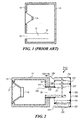
- a conventional bass-reflex loudspeaker system is shown.
- the system comprises an enclosure 11, a bass reflex port 14 with an outlet 12 and air volume 13 for resonating with respect to the enclosure air volume.
- a permanent magnet acoustic driver 16 is directly mounted to the front wall 15 of the enclosure 11. Due to the size of port 14, the enclosure 1 must be reasonably large compared to acoustic driver 6.
- the standard calculations used to determine the size of port 14 will give its acoustic area - the cross-sectional area in a plane perpendicular to the longitudinal axis of port 14 - and total length.
- FIGS 2 and 3 illustrates a first embodiment of the present invention.
- an enclosure 21 having a permanent magnet acoustic driver 26 mounted in the front wall 25 of the enclosure 21.
- Other types of acoustic drivers may of course be employed.
- the front wall 25 is not much larger than the acoustic driver 26.
- Enclosure 21 is made of a heat conductive material.
- the magnet assembly of acoustic driver 26, and the frame 27 of the acoustic driver 26 are made of metal and are therefore heat conductive, this enables the enclosure 21 to act as a dissipater of heat generated during, and by, the operation of acoustic driver 26.
- Enclosure 21 has a rear wall 28 with a central opening 29.
- central opening 29 is aligned and co-axial with acoustic driver 26.
- Mounted in central opening 29 and secured to rear wall 28 is an acoustic extension generally indicated as 210.
- the acoustic extension 210 is preferably co-axial with acoustic driver 26.
- the acoustic extension 210 may be any one of: a bass reflex port, a tuned port, a passive radiator and a concentric loading. For the remainder of the description it will be referred to as a "port" for simplicity.
- the port 210 defines a serpentine passage operatively connected to the interior of the enclosure 21.
- Port 210 has a central stem 211 that locates in opening 29 and engages with rear wall 28 using a threaded portion 212 on its outer surface, adhesives, screw fasteners, or the like. It is preferred that the engagement of central stem 211 and rear wall 28 is substantially air tight. It is also preferred for the central stem 211 to be adjustable relative to rear wall 28 to enable fine turning of the acoustic response of port 210 by moving the port 210 in the direction of the longitudinal axis of central stem 211. Central stem 211 may be moved axially inwardly or outwardly relative to rear wall 28.
- the port 210 may also be removable from enclosure 21 to enable different ports 210 to be used for different acoustic responses, and also for transport and/or storage.
- Central stem 211 is shown as being cylindrical.
- the effective length of central stem 211 from the inner surface of rear wall 28 to the end of central stem 211 remote from rear wall 28 is given as L 1 .
- the acoustic area of central stem 211 (the cross sectional area in a plane perpendicular to the longitudinal axis) is determined from its diameter D.
- the total acoustic length of port 210 is increased beyond L 1 by providing a plurality of columns 213 arranged concentrically with and about central stem 211 and having an outlet 226.
- Both the inner 215 and outer columns 216 are mounted to, and extend perpendicularly from, an outer wall 220 of the port 210 and towards an inner wall 221 of the port 210.
- Column 218 is mounted to and extends perpendicularly from the inner wall 221 and towards the outer wall 220.
- Column 215 extends generally concentrically with central stem 211 and is of a length such that an air gap 222 of desired size exists between its free end 223 and inner wall 221.
- Column 218 extends generally concentrically with central stem 211 and column 215 and is of a length such that an air gap 224 of desired size exists between its free end 225 and outer wall 220.
- Column 216 extends generally concentrically with central stem 211 and columns 215, 218 and is of a length such that it extends from outer wall 220 to a plane of inner wall 221. However, an outlet air gap 226 is provided between column 216 and inner wall 221.
- the port 210 has two halves.
- the first half is inner wall 221 with walls 211 and 218.
- the other half is outer wall 220 with walls 215 and 216.
- Wall 215 has an air gap 222 so it doesn't generally contact inner wall 221.
- Wall 218 has an air gap 224 so it doesn't generally contact outer wall 220.
- each of walls 215 and 218 has a series of spaced-apart, axially-extending, small projections 232 that contact and are secured to inner wall 221 and outer wall 220 respectively.
- the projections 232 should be of a length to give the required air gaps 222 and 224; but are preferably of sufficiently small cross-sectional area and spacing that their interference in air movement, and the acoustic response, is negligible.
- Projections 232 may be integral with one or more of walls 215, 218, 220 and 221.
- projections 232 may be formed on either or both of outer wall 220 and inner wall 221.
- the projections 832 may comprise a plurality of inner projections 833 that extend radially outwardly from inner wall 821, and a mating plurality of outer projections 834 that extend radially inwardly from outer wall 820 and overlap with projections 833.
- the projections 833, 834 may be secured together by a releasable fasteners such as, for example, a bolt or screw 835 (as shown), clips, adhesive tape, or otherwise; or non-releasably by, for example, glue, welding, or the like.
- the projections 833, 834 should be of a length to give the required air gap 826; but are preferably of sufficiently small cross-sectional area and spacing that their interference in air movement, and the acoustic response, is negligible.
- That gap 230 may be as little or as large as is required or desired.
- columns 215, 218, 216 are preferably also cylindrical. In this way columns are mounted to walls 220, 221 in an alternating and opposed manner.
- Central stem 211 defines an air volume 214 determined by D and L 1 .
- the columns 215, 216, 218 define an air volume 217 defined by the acoustic area of the width W 1 from central stem 211 to column 215, and the axial length of W 1 (L 2 , the distance between walls 220 and 221); the acoustic area of width W 2 from column 215 to column 218, and L 2 ; and the acoustic area of width W 3 from column 218 to column 216 and L 2 .
- the acoustic area of the width W 1 is the cross-sectional area in a plane perpendicular to the longitudinal axis and that is perpendicular to the plane of the page of Figure 2 .
- the acoustic area of W 1 is preferably the same as the acoustic area of the gap W 2 ; and the acoustic area of the gap W 3 is preferably the same as that of W 1 and W 2 .
- the acoustic areas of D, W 1 , W 2 and W 3 are all substantially identical.
- the total acoustic air volume of port 210 and thus the mass of air loading of port 210 is determined from:
- air gaps 222 and 224 are the same size.
- a significantly greater length of port, and greater air volume can be provided in a relatively small space. It can also be external of the speaker.
- air will be drawn into central stem 211 through inlet end 219, will pass through air volume 214 within central stem, and air volume 217 within columns 215, 218, 216, and pass out through outlet 226 as outlet airflow 229.
- air may be drawn into enclosure 21 to replace the lost air.
- air may oscillate back and forth as the driver. This will enhance the cooling of enclosure 21.
- air 229 passing out through outlet 226 will pass over at least part of enclosure 21 further increasing the cooling effect.
- An appropriate conical projection 228 may be provided at the centre of outer wall 220 and extending towards central stem 211 for similar reasons. The radius of curvature of junctions 227 and conical projection 228 may be determined as is required, or desired.
- the port 210 is external of enclosure 21 as it is not within the interior of enclosure 21 as occupied and used by acoustic driver 216.
- port 210 is generally cylindrical and has a circular cross-sectional shape. This is also shown in Figure 4(a) . It may be any other shape such as, for example, square (cuboid) ( Figure 4(b) ); triangular ( Figure 4(c) ) or octagonal ( Figure 4(d) ).
- the columns forming the port 210 may also be tapered or flared, and the inner and outer walls 220, 221 of port 210 may be curved, stepped, or some other non-planar configuration.
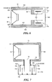
- Figure 5 shows a variation where the inner wall 521 is the rear wall 58, and the four side walls 531 of enclosure 51 are extended to form intermediate column 518. As such, airflow 529 from outlet 526 will be over at least a part of each of the four sides 531.
- Figure 6 shows a variation over Figures 5 .
- column 616 has been extended in length so that outlet 626 is substantially planar with front wall 65. In this way the outlet air 629 passes completely over each of the four side walls 631 to thus increase the cooling effect.
- central stem 611 is shown fixed to or integral with rear wall 68. In this case, column 615 may be adjustable relative to central stem 611 such as by use of screw threads 612.
- Figure 7 shows a variation of the previous embodiments. Although illustrated as a variation of the embodiment of Figures 2 and 3 , the variations of one or more of Figures 4 , 5 and 6 may also be incorporated into this embodiment.
- opening 79 is in lower wall 732 of enclosure 71 with port 710 arranged below enclosure 71.
- port 710 also acts as a stand or pedestal for enclosure 71. It is preferred for outlet 726 to be upwardly directed for audio clarity, and for gap 730 to be of a sufficient size for audio clarity.
- connection As used herein, the terms “connected”, “coupled”, “mounted” etc. are synonymous, and do not imply any directness of mounting/coupling/connecting between the components so joined. That is, the coupling/connecting/mounting of components may be direct or indirect (i.e. involving intermediate components).
Landscapes
- Health & Medical Sciences (AREA)
- Otolaryngology (AREA)
- Physics & Mathematics (AREA)
- Engineering & Computer Science (AREA)
- Acoustics & Sound (AREA)
- Signal Processing (AREA)
- Details Of Audible-Bandwidth Transducers (AREA)
- Obtaining Desirable Characteristics In Audible-Bandwidth Transducers (AREA)
Description
- This invention relates to a speaker with an externally-mounted acoustic extension and refers particularly, though not exclusively, to such a speaker where the speaker enclosure is relatively small.
- Bass reflex speakers have been known for some time. The enhanced low frequency response is due to the use of a port that is built-in to the speaker enclosure. That tends to make the speaker enclosure larger than would otherwise be the case due to the length of port required, the port generally having an outlet in the front wall of the speaker enclosure.
- With the use of small speaker enclosures in, for example, home theatre systems, computers sound systems, MP3 players, and the like producing an acceptable low-frequency response with small enclosures has been difficult.
- A passive radiator may be used but the small surface area of small enclosures becomes a significant limiting factor. Also a small piston diameter of the passive radiator decreases the sound pressure level at low frequencies.
- Finally, small speaker enclosures have an increased tendency towards overheating due to the low volume of air able to dissipate the heat generated within the speaker enclosure.
-
US 5,920,633 ,US 5,170,435 ,DE 3214226 andUS 4,298,087 all disclose speaker systems that have a waveguide or transmission line whose construction provides a greater effective length whilst only minimally increasing the size of the speaker system. In addition,US 5,406,637 discloses a speaker in which a duct is provided within the speaker's enclosure to enhance the bass response of the speaker, the length of the duct being adjustable so as to allow the resonance of the bass tones to be increased or decreased. However, none of these documents disclose a speaker system whose construction provides that the low frequency response of the speaker system can be easily and conveniently adjustable, whilst still allowing the speaker system to be relatively small in size. - In accordance with the invention there is provided a speaker comprising:
- (a) an enclosure with at least one wall;
- (b) an acoustic driver mounted in an interior of the enclosure and being attached to a front wall of the enclosure;
- (c) an acoustic extension being mounted to the enclosure externally of the enclosure and being operatively connected to the interior of the enclosure;
- (d) the enclosure and a frame of the acoustic driver being made of a heat conductive material;
- (e) the acoustic extension having an outlet air gap facing towards the enclosure to provide a cooling airflow over at least a part of the enclosure.
- The acoustic extension may be mounted in an opening in a rear wall of the enclosure and may be co-axial with the acoustic driver. Alternatively, the central stem may be mounted in an opening in a lower side wall of the enclosure, the acoustic extension acting as a pedestal for the enclosure.
- The acoustic extension may comprise a central stem, and a plurality of columns each being concentric with the central stem; the plurality of columns being mounted to an outer wall and an inner wall in an alternating and opposed manner to define therebetween an airflow passage operatively connected to the central stem and the interior.
- The plurality of columns may comprise an inner column mounted to the outer wall and extending towards the inner wall, there being an air gap between a free end of the inner column and the inner wall.
- Additionally or alternatively, the plurality of columns may comprise an intermediate column mounted to the inner wall and extending towards the outer wall, there being an air gap between a free end of the intermediate column and the outer wall.
- Further additionally or alternatively, the plurality of columns may comprise an outer column mounted to the outer wall and extending to a plane of the inner wall, there being an outlet air gap between the outer column and the inner wall.
- The outlet air gap faces towards the enclosure. All junctions between each of the plurality of columns and each of the outer wall and inner wall may be curved.
- Preferably, the enclosure comprises four mutually perpendicular side walls, the four mutually perpendicular side walls being extended to comprise the intermediate column. The outer column may extend forwardly to a plane of the front wall.
- The central stem may define an air volume, the air volume and the airflow passage preferably being of a constant acoustic area.
- The acoustic extension may be adjustable relative to the wall in a direction of a longitudinal axis of the central stem. The acoustic extension may be removably attached to the enclosure.
- The enclosure and a frame of the acoustic driver are made of a heat conductive material.
- The acoustic extension may be any one of : a bass reflex port, a tuned port, a passive radiator, or a concentric loading.
- In order that the invention may be clearly understood and readily put into practical effect, there shall now be described by way of non-limitative example, only preferred embodiments of the present invention, the description being with reference to the accompanying illustrative drawings in which:
-
Figure 1 is a cross-sectional view of a prior art bass-reflex loudspeaker. -
Figure 2 is a cross sectional view of a first embodiment of the present invention; -
Figure 3 is a perspective cross sectional view of the external acoustic extension ofFigure 2 ; -
Figures 4 a, b, c, d are cross sectional views of various external acoustic extension; -
Figure 5a is a cross-sectional view of a second embodiment of the present invention; -
Figure 5b is a perspective view from the front of the embodiment ofFig 5a ; -
Figure 5c is a perspective view from the rear of the embodiment ofFig 5a ; -
Figure 6 is a cross-sectional view of a further embodiment; -
Figure 7 is a cross-sectional view of a final embodiment; and -
Figure 8 is a variation on the embodiment ofFigures 2 and3 . - Throughout the drawings like components have like reference numerals but with a prefix number indicating the Figure number (except for
Figure 3 ). - With reference to
Figure 1 , a conventional bass-reflex loudspeaker system is shown. The system comprises anenclosure 11, abass reflex port 14 with anoutlet 12 andair volume 13 for resonating with respect to the enclosure air volume. A permanent magnetacoustic driver 16 is directly mounted to thefront wall 15 of theenclosure 11. Due to the size ofport 14, the enclosure 1 must be reasonably large compared to acoustic driver 6. The standard calculations used to determine the size ofport 14 will give its acoustic area - the cross-sectional area in a plane perpendicular to the longitudinal axis of port 14 - and total length. -
Figures 2 and3 illustrates a first embodiment of the present invention. Here there is anenclosure 21 having a permanent magnetacoustic driver 26 mounted in thefront wall 25 of theenclosure 21. Other types of acoustic drivers may of course be employed. As can be seen, thefront wall 25 is not much larger than theacoustic driver 26.Enclosure 21 is made of a heat conductive material. As the magnet assembly ofacoustic driver 26, and theframe 27 of theacoustic driver 26, are made of metal and are therefore heat conductive, this enables theenclosure 21 to act as a dissipater of heat generated during, and by, the operation ofacoustic driver 26. -
Enclosure 21 has arear wall 28 with acentral opening 29. Preferably,central opening 29 is aligned and co-axial withacoustic driver 26. Mounted incentral opening 29 and secured torear wall 28 is an acoustic extension generally indicated as 210. Theacoustic extension 210 is preferably co-axial withacoustic driver 26. Theacoustic extension 210 may be any one of: a bass reflex port, a tuned port, a passive radiator and a concentric loading. For the remainder of the description it will be referred to as a "port" for simplicity. - As can be seen from
Figures 2 and3 , theport 210 defines a serpentine passage operatively connected to the interior of theenclosure 21. -
Port 210 has acentral stem 211 that locates in opening 29 and engages withrear wall 28 using a threadedportion 212 on its outer surface, adhesives, screw fasteners, or the like. It is preferred that the engagement ofcentral stem 211 andrear wall 28 is substantially air tight. It is also preferred for thecentral stem 211 to be adjustable relative torear wall 28 to enable fine turning of the acoustic response ofport 210 by moving theport 210 in the direction of the longitudinal axis ofcentral stem 211.Central stem 211 may be moved axially inwardly or outwardly relative torear wall 28. - The
port 210 may also be removable fromenclosure 21 to enabledifferent ports 210 to be used for different acoustic responses, and also for transport and/or storage. -
Central stem 211 is shown as being cylindrical. The effective length ofcentral stem 211 from the inner surface ofrear wall 28 to the end ofcentral stem 211 remote fromrear wall 28 is given as L1. The acoustic area of central stem 211 (the cross sectional area in a plane perpendicular to the longitudinal axis) is determined from its diameter D. - In the case of a concentric loading, the total acoustic length of
port 210 is increased beyond L1 by providing a plurality ofcolumns 213 arranged concentrically with and aboutcentral stem 211 and having anoutlet 226. There may be any required number of columns 213 - two, three, four, five, and so forth, depending on the total acoustic length needed forport 210. As shown inFigure 3 , in the illustrated embodiment there are three such columns 213 - aninner column 215, anintermediate column 218 and anouter column 216. By having an odd number of columns 213 (3, 5, 7 etc) theoutlet 226 faces forwards, a preferred result Both the inner 215 andouter columns 216 are mounted to, and extend perpendicularly from, anouter wall 220 of theport 210 and towards aninner wall 221 of theport 210.Column 218 is mounted to and extends perpendicularly from theinner wall 221 and towards theouter wall 220. -
Column 215 extends generally concentrically withcentral stem 211 and is of a length such that anair gap 222 of desired size exists between itsfree end 223 andinner wall 221.Column 218 extends generally concentrically withcentral stem 211 andcolumn 215 and is of a length such that anair gap 224 of desired size exists between itsfree end 225 andouter wall 220.Column 216 extends generally concentrically withcentral stem 211 andcolumns outer wall 220 to a plane ofinner wall 221. However, anoutlet air gap 226 is provided betweencolumn 216 andinner wall 221. - As such, the
port 210 has two halves. The first half isinner wall 221 withwalls outer wall 220 withwalls -
Wall 215 has anair gap 222 so it doesn't generally contactinner wall 221.Wall 218 has anair gap 224 so it doesn't generally contactouter wall 220. To provide a physical contact between the two halves and to keep them the necessary distance apart to createair gaps walls small projections 232 that contact and are secured toinner wall 221 andouter wall 220 respectively. Theprojections 232 should be of a length to give the requiredair gaps Projections 232 may be integral with one or more ofwalls - Additionally or alternatively,
projections 232 may be formed on either or both ofouter wall 220 andinner wall 221. - As is shown in
Figure 8 , the projections 832 may comprise a plurality ofinner projections 833 that extend radially outwardly from inner wall 821, and a mating plurality ofouter projections 834 that extend radially inwardly from outer wall 820 and overlap withprojections 833. Theprojections projections air gap 826; but are preferably of sufficiently small cross-sectional area and spacing that their interference in air movement, and the acoustic response, is negligible. - There may be a
gap 230 betweeninner wall 221 andrear wall 28. Thatgap 230 may be as little or as large as is required or desired. - As
central stem 211 is cylindrical,columns walls -
Central stem 211 defines anair volume 214 determined by D and L1. Thecolumns air volume 217 defined by the acoustic area of the width W1 fromcentral stem 211 tocolumn 215, and the axial length of W1 (L2, the distance betweenwalls 220 and 221); the acoustic area of width W2 fromcolumn 215 tocolumn 218, and L2; and the acoustic area of width W3 fromcolumn 218 tocolumn 216 and L2. - The acoustic area of the width W1 is the cross-sectional area in a plane perpendicular to the longitudinal axis and that is perpendicular to the plane of the page of
Figure 2 . The acoustic area of W1 is preferably the same as the acoustic area of the gap W2; and the acoustic area of the gap W3 is preferably the same as that of W1 and W2. Most preferably, the acoustic areas of D, W1, W2 and W3 are all substantially identical. - Therefore, the total acoustic air volume of
port 210 and thus the mass of air loading ofport 210 is determined from: - D and L1;
- W1 and L2;
- W2 and L2; and
- W3 and L2.
- This can generally be designated as:

- Preferably,
air gaps - In operation, air will be drawn into
central stem 211 throughinlet end 219, will pass throughair volume 214 within central stem, andair volume 217 withincolumns outlet 226 asoutlet airflow 229. As such, air may be drawn intoenclosure 21 to replace the lost air. Alternatively or additionally, air may oscillate back and forth as the driver. This will enhance the cooling ofenclosure 21. Furthermore,air 229 passing out throughoutlet 226 will pass over at least part ofenclosure 21 further increasing the cooling effect. - All
junctions 227 betweencentral stem 211 andinner wall 221,inner wall 221 andcolumn 218,outer wall 220 andcolumn 215, andouter wall 220 andcolumn 216, preferably are curved or arcuate (as shown onFigure 2 ) to reduce airflow restrictions, reduce airflow turbulence, and to reduce airflow noise. An appropriateconical projection 228 may be provided at the centre ofouter wall 220 and extending towardscentral stem 211 for similar reasons. The radius of curvature ofjunctions 227 andconical projection 228 may be determined as is required, or desired. - The
port 210 is external ofenclosure 21 as it is not within the interior ofenclosure 21 as occupied and used byacoustic driver 216. - As is described above,
port 210 is generally cylindrical and has a circular cross-sectional shape. This is also shown inFigure 4(a) . It may be any other shape such as, for example, square (cuboid) (Figure 4(b) ); triangular (Figure 4(c) ) or octagonal (Figure 4(d) ). In addition, the columns forming theport 210 may also be tapered or flared, and the inner andouter walls port 210 may be curved, stepped, or some other non-planar configuration. -
Figure 5 shows a variation where theinner wall 521 is therear wall 58, and the fourside walls 531 ofenclosure 51 are extended to form intermediate column 518. As such,airflow 529 fromoutlet 526 will be over at least a part of each of the foursides 531. -
Figure 6 shows a variation overFigures 5 . Here,column 616 has been extended in length so thatoutlet 626 is substantially planar withfront wall 65. In this way theoutlet air 629 passes completely over each of the fourside walls 631 to thus increase the cooling effect. Also,central stem 611 is shown fixed to or integral withrear wall 68. In this case,column 615 may be adjustable relative tocentral stem 611 such as by use ofscrew threads 612. -
Figure 7 shows a variation of the previous embodiments. Although illustrated as a variation of the embodiment ofFigures 2 and3 , the variations of one or more ofFigures 4 ,5 and6 may also be incorporated into this embodiment. Here, opening 79 is inlower wall 732 ofenclosure 71 withport 710 arranged belowenclosure 71. Thus port 710 also acts as a stand or pedestal forenclosure 71. It is preferred foroutlet 726 to be upwardly directed for audio clarity, and forgap 730 to be of a sufficient size for audio clarity. - As used herein, the terms "connected", "coupled", "mounted" etc. are synonymous, and do not imply any directness of mounting/coupling/connecting between the components so joined. That is, the coupling/connecting/mounting of components may be direct or indirect (i.e. involving intermediate components).
- Whilst there has been described in the foregoing description a number of embodiments of the present invention, it will be understood by those skilled in the technology concerned that many variations or modifications in details of design and construction may be made without departing from the present invention, as defined in the claims.
Claims (12)
- A speaker comprising:(a) an enclosure (21) with at least one wall;(b) an acoustic driver (26) being attached to a front wall (25) of the enclosure wherein the enclosure and a frame of the acoustic driver are made from a heat conductive material;(c) an acoustic extension (210) being mounted to the enclosure (21)
;
wherein the acoustic extension (210) is externally mounted to the enclosure (21) and is operatively connected to an interior of the enclosure (21), and the acoustic extension (210) defines a serpentine passage operatively connected to the interior of the enclosure (21).
and wherein the acoustic extension has an outlet (226) facing towards the enclosure. - A speaker as claimed in claim 1, wherein the acoustic extension (210) is mounted in an opening in a rear wall of the enclosure (21) and is generally co- axial with the acoustic driver (26).
- A speaker as claimed in any one of claims 1 to 2, wherein the acoustic extension (210) comprises a central stem (211), and a plurality of columns (213) each being generally concentric with the central stem (211); the plurality of columns (213) being mounted to an outer wall of the acoustic extension (210) and an inner wall of the acoustic extension (210) in an alternating and opposed manner to define therebetween an airflow passage operatively connected to the central stem (211) and the interior.
- A speaker as claimed in claim 3, wherein the plurality of columns (213) is selected from the group comprising:(a) an inner column (215) mounted to the outer wall (220) and extending towards the inner wall (221), there being an air gap between a free end of the inner column and the inner wall;(b) an intermediate column (218) mounted to the inner wall (221) and extending towards the outer wall (220), there being an air gap between a free end of the intermediate column and the outer wall; and(c) an outer column (216) mounted to the outer wall (220) and extending towards a plane of the inner wall (221), there being an outlet air gap between the outer column and the inner wall;
or a combination of all of the aforementioned. - A speaker as claimed in claim 3, wherein junctions between the plurality of columns (213) and each of the outer wall (220) and inner wall (221), are curved.
- A speaker as claimed in claim 4, wherein the enclosure (21) comprises four mutually perpendicular side walls, the four mutually perpendicular side walls being extended to comprise the intermediate column.
- A speaker as claimed in claim 6, wherein the outer column (216) extends forwardly to the vicinity of the front wall (15).
- A speaker as claimed in claim 3, wherein the central stem (211) defines an air volume, the air volume and the airflow passage being of a constant acoustic area.
- A speaker as claimed in claim 3, wherein the acoustic extension (210) is adjustable relative to the enclosure (21) in a direction of a longitudinal axis of the central stem (211).
- A speaker as claimed in any one of claims 1 to 9, wherein the acoustic extension (210) is removably attached to the enclosure (21).
- A speaker as claimed in any one of claims 1 to 10, wherein the acoustic extension (210) is selected from the group consisting of: a bass reflex port, a tuned port, a passive radiator, and a concentric loading.
- A speaker as claimed in claim 3, wherein the central stem (211) is mounted in an opening in a lower side wall of the enclosure (21), the acoustic extension (210) acting as a pedestal for the enclosure.
Applications Claiming Priority (2)
| Application Number | Priority Date | Filing Date | Title |
|---|---|---|---|
| US10/764,172 US7450733B2 (en) | 2004-01-23 | 2004-01-23 | Speaker with externally mounted acoustic extension |
| PCT/SG2005/000003 WO2005072005A1 (en) | 2004-01-23 | 2005-01-12 | Speaker with externally-mounted acoustic extension |
Publications (3)
| Publication Number | Publication Date |
|---|---|
| EP1709832A1 EP1709832A1 (en) | 2006-10-11 |
| EP1709832A4 EP1709832A4 (en) | 2009-03-25 |
| EP1709832B1 true EP1709832B1 (en) | 2013-05-22 |
Family
ID=34795228
Family Applications (1)
| Application Number | Title | Priority Date | Filing Date |
|---|---|---|---|
| EP05704823.3A Expired - Lifetime EP1709832B1 (en) | 2004-01-23 | 2005-01-12 | Speaker with externally-mounted acoustic extension |
Country Status (4)
| Country | Link |
|---|---|
| US (1) | US7450733B2 (en) |
| EP (1) | EP1709832B1 (en) |
| TW (1) | TWI356641B (en) |
| WO (1) | WO2005072005A1 (en) |
Cited By (1)
| Publication number | Priority date | Publication date | Assignee | Title |
|---|---|---|---|---|
| US11128941B1 (en) | 2018-11-20 | 2021-09-21 | Edward G. Blemel | Method for passive dissipation of deconstructive harmonics during audio amplification and reproduction |
Families Citing this family (24)
| Publication number | Priority date | Publication date | Assignee | Title |
|---|---|---|---|---|
| US7093688B2 (en) * | 2001-09-05 | 2006-08-22 | Samsung Electronics Co., Ltd. | Structure for preventing the generation of standing waves and a method for implementing the same |
| US7961900B2 (en) * | 2005-06-29 | 2011-06-14 | Motorola Mobility, Inc. | Communication device with single output audio transducer |
| US20070158134A1 (en) * | 2006-01-11 | 2007-07-12 | Fryette Steven M | Speaker cabinet acoustics control mechanism |
| US20080169150A1 (en) * | 2007-01-12 | 2008-07-17 | Tsung-Cheng Kuo | Reflection-type sound box |
| US8489214B2 (en) * | 2007-02-07 | 2013-07-16 | Creative Technology Ltd | Dock without a power source for digital devices |
| US20090052723A1 (en) * | 2007-08-22 | 2009-02-26 | Hi-Tech Sound System Co., Ltd. | Speaker cabinet assembly for a speaker system |
| CN101442694B (en) * | 2007-11-20 | 2012-03-14 | 深圳富泰宏精密工业有限公司 | Loudspeaker assembly |
| US20090169040A1 (en) * | 2007-12-27 | 2009-07-02 | Motorola Inc | Devices and methods for enhancing the frequency output of a portable audio device |
| US8712086B2 (en) | 2007-12-27 | 2014-04-29 | Motorola Mobility Llc | Acoustic reconfiguration devices and methods |
| US8345909B2 (en) * | 2008-04-03 | 2013-01-01 | Bose Corporation | Loudspeaker assembly |
| US8311258B2 (en) * | 2009-03-11 | 2012-11-13 | Cheng Uei Precision Industry Co., Ltd. | Headset |
| US8275164B1 (en) | 2010-10-07 | 2012-09-25 | Nguyen Thach T | Speaker enclosures |
| US9179213B2 (en) * | 2012-11-07 | 2015-11-03 | Long Ngoc Pham | Speaker apparatus for producing sound |
| US8913777B2 (en) * | 2013-02-06 | 2014-12-16 | Bose Corporation | Providing speakers in a vehicle seat |
| CN105144743B (en) * | 2013-03-22 | 2019-03-29 | 闪耀声音技术有限公司 | acoustic device |
| DE102014101826B4 (en) * | 2014-02-13 | 2016-08-04 | Tenneco Gmbh | Sounder system for a motor vehicle |
| CN106303771B (en) | 2015-05-28 | 2020-01-03 | 迪芬尼香港有限公司 | Omnidirectional phase reversal sound box structure |
| DE102016119475B4 (en) * | 2016-10-12 | 2019-02-21 | Norman Gerkinsmeyer | Sound absorber and vehicle, and use of a sound absorber |
| CN106792335B (en) * | 2017-01-05 | 2019-09-06 | 联想(北京)有限公司 | A kind of electronic equipment |
| EP3477629B1 (en) * | 2017-10-30 | 2021-12-01 | Alpine Electronics, Inc. | Vehicle loudspeaker system and vehicle structure comprising such loudspeaker system |
| JP7213065B2 (en) * | 2018-02-07 | 2023-01-26 | パナソニック インテレクチュアル プロパティ コーポレーション オブ アメリカ | speaker system |
| US10616678B2 (en) * | 2018-05-08 | 2020-04-07 | Crestron Electronics, Inc. | Tunable bass reflex ceiling mounted speaker system |
| DE102019108423B4 (en) * | 2019-04-01 | 2021-08-05 | Svetlomir Aleksandrov | Loudspeaker box and loudspeaker |
| US11330364B1 (en) | 2021-01-12 | 2022-05-10 | Robert Bosch Gmbh | Ported speaker assembly |
Citations (1)
| Publication number | Priority date | Publication date | Assignee | Title |
|---|---|---|---|---|
| WO1996031105A1 (en) * | 1995-03-31 | 1996-10-03 | Bsg Laboratories, Inc. | Low frequency audio coupler and method of coupling |
Family Cites Families (37)
| Publication number | Priority date | Publication date | Assignee | Title |
|---|---|---|---|---|
| US2971598A (en) | 1956-08-23 | 1961-02-14 | Sieler George Jerome | Loud speaker |
| US3327808A (en) * | 1965-06-10 | 1967-06-27 | Dyna Empire Inc | Loud speaker housing |
| US3778551A (en) | 1969-01-17 | 1973-12-11 | Chicago Musical Instr Co | Air cooled audio amplifier assembly |
| US4126204A (en) * | 1976-02-02 | 1978-11-21 | Trio Kabushiki Kaisha | Speaker system |
| DE2607390C2 (en) * | 1976-02-24 | 1982-09-23 | Braun Ag, 6000 Frankfurt | Dynamic loudspeaker with a high load capacity |
| US4168761A (en) * | 1976-09-03 | 1979-09-25 | George Pappanikolaou | Symmetrical air friction enclosure for speakers |
| US4142603A (en) * | 1976-11-22 | 1979-03-06 | Johnson Rubein V | Adjustable speaker cabinet |
| JPS571500Y2 (en) | 1977-06-08 | 1982-01-11 | ||
| FR2433879A1 (en) | 1978-08-16 | 1980-03-14 | Launay Dominique | UNIDIRECTIONAL ACOUSTIC SPEAKER |
| US4229304A (en) * | 1979-09-21 | 1980-10-21 | Envirotech Corporation | Molded thermoplastic filter plate |
| US4509615A (en) | 1980-02-04 | 1985-04-09 | Hruby John O | Multi-chamber enclosure for loudspeakers |
| US4299304A (en) | 1980-07-01 | 1981-11-10 | Rebsch Gary A | Exponential folded horn speaker enclosure |
| DK147490C (en) | 1981-02-03 | 1985-05-28 | Jamo Hi Fi As | Bass-reflex speaker system |
| DE3214226C2 (en) | 1982-04-17 | 1987-02-26 | Standard Elektrik Lorenz Ag, 7000 Stuttgart | Loudspeaker with sound bypass |
| US4889208A (en) * | 1987-02-23 | 1989-12-26 | Katsutoshi Sugihara | Speaker enclosures |
| US5025474A (en) * | 1987-09-29 | 1991-06-18 | Matsushita Electric Industrial Co., Ltd. | Speaker system with image projection screen |
| US5170435A (en) * | 1990-06-28 | 1992-12-08 | Bose Corporation | Waveguide electroacoustical transducing |
| US5082084A (en) * | 1990-07-23 | 1992-01-21 | Ye Ming Tsao | Extensible sound case |
| US5197103A (en) | 1990-10-05 | 1993-03-23 | Kabushiki Kaisha Kenwood | Low sound loudspeaker system |
| US5357586A (en) | 1991-05-16 | 1994-10-18 | The Nordschow/Wright Loudspeaker Company | Flow-through air-cooled loudspeaker system |
| US5373564A (en) * | 1992-10-02 | 1994-12-13 | Spear; Robert J. | Transmission line for planar waves |
| US5406637A (en) * | 1993-10-04 | 1995-04-11 | Gonzalez; Hector M. | Speaker enclosure assembly |
| US5517573A (en) * | 1994-01-04 | 1996-05-14 | Polk Investment Corporation | Ported loudspeaker system and method with reduced air turbulence |
| US5809154A (en) * | 1994-01-04 | 1998-09-15 | Britannia Investment Corporation | Ported loudspeaker system and method |
| US5533132A (en) * | 1995-01-23 | 1996-07-02 | Jbl Incorporated | Loudspeaker thermal management structure |
| US5821471A (en) * | 1995-11-30 | 1998-10-13 | Mcculler; Mark A. | Acoustic system |
| US5920633A (en) * | 1996-02-12 | 1999-07-06 | Yang; Yi-Fu | Thin-wall multi-concentric cylinder speaker enclosure with audio amplifier tunable to listening room |
| US5824969A (en) * | 1996-09-30 | 1998-10-20 | Takenaka; Masaaki | Speaker system with a three-dimensional spiral sound passage |
| US6411721B1 (en) * | 1997-12-19 | 2002-06-25 | William E. Spindler | Audio speaker with harmonic enclosure |
| JPH11234783A (en) * | 1998-02-13 | 1999-08-27 | Masaaki Takenaka | Speaker system |
| US6144751A (en) | 1998-02-24 | 2000-11-07 | Velandia; Erich M. | Concentrically aligned speaker enclosure |
| US6549637B1 (en) | 1998-09-24 | 2003-04-15 | Peavey Electronics Corp. | Loudspeaker with differential flow vent means |
| US6504938B1 (en) * | 2000-10-06 | 2003-01-07 | Logitech Europe S.A. | Dual-chamber loudspeaker |
| US6604602B1 (en) | 2002-09-30 | 2003-08-12 | Chae Yong Kim | Separable speaker cover box containing speaker system |
| US6973994B2 (en) * | 2002-11-04 | 2005-12-13 | Mackin Ian J | Apparatus for increasing the quality of sound from an acoustic source |
| US7162049B2 (en) * | 2003-01-07 | 2007-01-09 | Britannia Investment Corporation | Ported loudspeaker system and method with reduced air turbulence, bipolar radiation pattern and novel appearance |
| US7039212B2 (en) * | 2003-09-12 | 2006-05-02 | Britannia Investment Corporation | Weather resistant porting |
-
2004
- 2004-01-23 US US10/764,172 patent/US7450733B2/en not_active Expired - Lifetime
-
2005
- 2005-01-12 EP EP05704823.3A patent/EP1709832B1/en not_active Expired - Lifetime
- 2005-01-12 WO PCT/SG2005/000003 patent/WO2005072005A1/en not_active Ceased
- 2005-01-14 TW TW094101134A patent/TWI356641B/en not_active IP Right Cessation
Patent Citations (1)
| Publication number | Priority date | Publication date | Assignee | Title |
|---|---|---|---|---|
| WO1996031105A1 (en) * | 1995-03-31 | 1996-10-03 | Bsg Laboratories, Inc. | Low frequency audio coupler and method of coupling |
Cited By (1)
| Publication number | Priority date | Publication date | Assignee | Title |
|---|---|---|---|---|
| US11128941B1 (en) | 2018-11-20 | 2021-09-21 | Edward G. Blemel | Method for passive dissipation of deconstructive harmonics during audio amplification and reproduction |
Also Published As
| Publication number | Publication date |
|---|---|
| TWI356641B (en) | 2012-01-11 |
| US7450733B2 (en) | 2008-11-11 |
| TW200527933A (en) | 2005-08-16 |
| WO2005072005A1 (en) | 2005-08-04 |
| EP1709832A1 (en) | 2006-10-11 |
| US20050163334A1 (en) | 2005-07-28 |
| EP1709832A4 (en) | 2009-03-25 |
Similar Documents
| Publication | Publication Date | Title |
|---|---|---|
| US7450733B2 (en) | Speaker with externally mounted acoustic extension | |
| US7162049B2 (en) | Ported loudspeaker system and method with reduced air turbulence, bipolar radiation pattern and novel appearance | |
| US4942939A (en) | Speaker system with folded audio transmission passage | |
| EP1284585B1 (en) | Electroacoustic waveguide | |
| US9854353B2 (en) | Omni-directional ported speaker | |
| EP1577880A2 (en) | An audio system comprising a waveguide having an audio source at one end and an acoustic driver at another end | |
| US20070256888A1 (en) | Speaker System With Improved Frequency Response | |
| CA2674467C (en) | High output loudspeaker | |
| EP2941012B1 (en) | Speaker system | |
| WO2014004617A1 (en) | Loudspeaker having an acoustic filter | |
| US7466837B2 (en) | Diffuser and speaker using the same | |
| US20090173567A1 (en) | Folded triangular sidewall ducted ports for loudspeaker enclosure | |
| US20010037910A1 (en) | Loudspeaker enclosure | |
| JP4124727B2 (en) | Electroacoustic loudspeaker with horn or acoustic waveguide | |
| JPWO2007034781A1 (en) | Speaker, speaker diaphragm and suspension | |
| CN117957857A (en) | Horn Loaded Loudspeaker | |
| JP3611854B2 (en) | Speaker system | |
| US9473848B2 (en) | Transmission line loudspeaker | |
| WO2015038394A1 (en) | Transmission line loudspeaker | |
| US20050175206A1 (en) | Loudspeaker assembly having a folded bifurcated vent tube | |
| EP1736029A1 (en) | Distributed acoustic cabinet | |
| US20060227983A1 (en) | Acoustic device | |
| JP2025108459A (en) | Loudspeaker system, method and apparatus for absorbing acoustic resonances of loudspeakers - Patents.com | |
| JP2008124855A (en) | Speaker device | |
| JP2010034948A (en) | Acoustic playback speaker system |
Legal Events
| Date | Code | Title | Description |
|---|---|---|---|
| PUAI | Public reference made under article 153(3) epc to a published international application that has entered the european phase |
Free format text: ORIGINAL CODE: 0009012 |
|
| 17P | Request for examination filed |
Effective date: 20060818 |
|
| AK | Designated contracting states |
Kind code of ref document: A1 Designated state(s): AT BE BG CH CY CZ DE DK EE ES FI FR GB GR HU IE IS IT LI LT LU MC NL PL PT RO SE SI SK TR |
|
| DAX | Request for extension of the european patent (deleted) | ||
| A4 | Supplementary search report drawn up and despatched |
Effective date: 20090224 |
|
| 17Q | First examination report despatched |
Effective date: 20100823 |
|
| GRAP | Despatch of communication of intention to grant a patent |
Free format text: ORIGINAL CODE: EPIDOSNIGR1 |
|
| RIC1 | Information provided on ipc code assigned before grant |
Ipc: H04R 1/28 20060101AFI20130121BHEP Ipc: H04R 9/02 20060101ALN20130121BHEP |
|
| RIC1 | Information provided on ipc code assigned before grant |
Ipc: H04R 9/02 20060101ALI20130125BHEP Ipc: H04R 1/28 20060101AFI20130125BHEP |
|
| GRAS | Grant fee paid |
Free format text: ORIGINAL CODE: EPIDOSNIGR3 |
|
| GRAA | (expected) grant |
Free format text: ORIGINAL CODE: 0009210 |
|
| AK | Designated contracting states |
Kind code of ref document: B1 Designated state(s): AT BE BG CH CY CZ DE DK EE ES FI FR GB GR HU IE IS IT LI LT LU MC NL PL PT RO SE SI SK TR |
|
| REG | Reference to a national code |
Ref country code: GB Ref legal event code: FG4D |
|
| REG | Reference to a national code |
Ref country code: CH Ref legal event code: EP |
|
| REG | Reference to a national code |
Ref country code: AT Ref legal event code: REF Ref document number: 613744 Country of ref document: AT Kind code of ref document: T Effective date: 20130615 |
|
| REG | Reference to a national code |
Ref country code: IE Ref legal event code: FG4D |
|
| REG | Reference to a national code |
Ref country code: DE Ref legal event code: R096 Ref document number: 602005039679 Country of ref document: DE Effective date: 20130718 |
|
| REG | Reference to a national code |
Ref country code: AT Ref legal event code: MK05 Ref document number: 613744 Country of ref document: AT Kind code of ref document: T Effective date: 20130522 |
|
| REG | Reference to a national code |
Ref country code: LT Ref legal event code: MG4D |
|
| PG25 | Lapsed in a contracting state [announced via postgrant information from national office to epo] |
Ref country code: PT Free format text: LAPSE BECAUSE OF FAILURE TO SUBMIT A TRANSLATION OF THE DESCRIPTION OR TO PAY THE FEE WITHIN THE PRESCRIBED TIME-LIMIT Effective date: 20130923 Ref country code: SE Free format text: LAPSE BECAUSE OF FAILURE TO SUBMIT A TRANSLATION OF THE DESCRIPTION OR TO PAY THE FEE WITHIN THE PRESCRIBED TIME-LIMIT Effective date: 20130522 Ref country code: SI Free format text: LAPSE BECAUSE OF FAILURE TO SUBMIT A TRANSLATION OF THE DESCRIPTION OR TO PAY THE FEE WITHIN THE PRESCRIBED TIME-LIMIT Effective date: 20130522 Ref country code: LT Free format text: LAPSE BECAUSE OF FAILURE TO SUBMIT A TRANSLATION OF THE DESCRIPTION OR TO PAY THE FEE WITHIN THE PRESCRIBED TIME-LIMIT Effective date: 20130522 Ref country code: IS Free format text: LAPSE BECAUSE OF FAILURE TO SUBMIT A TRANSLATION OF THE DESCRIPTION OR TO PAY THE FEE WITHIN THE PRESCRIBED TIME-LIMIT Effective date: 20130922 Ref country code: FI Free format text: LAPSE BECAUSE OF FAILURE TO SUBMIT A TRANSLATION OF THE DESCRIPTION OR TO PAY THE FEE WITHIN THE PRESCRIBED TIME-LIMIT Effective date: 20130522 Ref country code: GR Free format text: LAPSE BECAUSE OF FAILURE TO SUBMIT A TRANSLATION OF THE DESCRIPTION OR TO PAY THE FEE WITHIN THE PRESCRIBED TIME-LIMIT Effective date: 20130823 Ref country code: AT Free format text: LAPSE BECAUSE OF FAILURE TO SUBMIT A TRANSLATION OF THE DESCRIPTION OR TO PAY THE FEE WITHIN THE PRESCRIBED TIME-LIMIT Effective date: 20130522 Ref country code: ES Free format text: LAPSE BECAUSE OF FAILURE TO SUBMIT A TRANSLATION OF THE DESCRIPTION OR TO PAY THE FEE WITHIN THE PRESCRIBED TIME-LIMIT Effective date: 20130902 |
|
| REG | Reference to a national code |
Ref country code: NL Ref legal event code: VDEP Effective date: 20130522 |
|
| PG25 | Lapsed in a contracting state [announced via postgrant information from national office to epo] |
Ref country code: PL Free format text: LAPSE BECAUSE OF FAILURE TO SUBMIT A TRANSLATION OF THE DESCRIPTION OR TO PAY THE FEE WITHIN THE PRESCRIBED TIME-LIMIT Effective date: 20130522 Ref country code: BG Free format text: LAPSE BECAUSE OF FAILURE TO SUBMIT A TRANSLATION OF THE DESCRIPTION OR TO PAY THE FEE WITHIN THE PRESCRIBED TIME-LIMIT Effective date: 20130822 |
|
| PG25 | Lapsed in a contracting state [announced via postgrant information from national office to epo] |
Ref country code: DK Free format text: LAPSE BECAUSE OF FAILURE TO SUBMIT A TRANSLATION OF THE DESCRIPTION OR TO PAY THE FEE WITHIN THE PRESCRIBED TIME-LIMIT Effective date: 20130522 Ref country code: EE Free format text: LAPSE BECAUSE OF FAILURE TO SUBMIT A TRANSLATION OF THE DESCRIPTION OR TO PAY THE FEE WITHIN THE PRESCRIBED TIME-LIMIT Effective date: 20130522 Ref country code: CZ Free format text: LAPSE BECAUSE OF FAILURE TO SUBMIT A TRANSLATION OF THE DESCRIPTION OR TO PAY THE FEE WITHIN THE PRESCRIBED TIME-LIMIT Effective date: 20130522 Ref country code: BE Free format text: LAPSE BECAUSE OF FAILURE TO SUBMIT A TRANSLATION OF THE DESCRIPTION OR TO PAY THE FEE WITHIN THE PRESCRIBED TIME-LIMIT Effective date: 20130522 Ref country code: SK Free format text: LAPSE BECAUSE OF FAILURE TO SUBMIT A TRANSLATION OF THE DESCRIPTION OR TO PAY THE FEE WITHIN THE PRESCRIBED TIME-LIMIT Effective date: 20130522 |
|
| PG25 | Lapsed in a contracting state [announced via postgrant information from national office to epo] |
Ref country code: NL Free format text: LAPSE BECAUSE OF FAILURE TO SUBMIT A TRANSLATION OF THE DESCRIPTION OR TO PAY THE FEE WITHIN THE PRESCRIBED TIME-LIMIT Effective date: 20130522 Ref country code: IT Free format text: LAPSE BECAUSE OF FAILURE TO SUBMIT A TRANSLATION OF THE DESCRIPTION OR TO PAY THE FEE WITHIN THE PRESCRIBED TIME-LIMIT Effective date: 20130522 Ref country code: RO Free format text: LAPSE BECAUSE OF FAILURE TO SUBMIT A TRANSLATION OF THE DESCRIPTION OR TO PAY THE FEE WITHIN THE PRESCRIBED TIME-LIMIT Effective date: 20130522 |
|
| PLBE | No opposition filed within time limit |
Free format text: ORIGINAL CODE: 0009261 |
|
| STAA | Information on the status of an ep patent application or granted ep patent |
Free format text: STATUS: NO OPPOSITION FILED WITHIN TIME LIMIT |
|
| 26N | No opposition filed |
Effective date: 20140225 |
|
| REG | Reference to a national code |
Ref country code: DE Ref legal event code: R097 Ref document number: 602005039679 Country of ref document: DE Effective date: 20140225 |
|
| PG25 | Lapsed in a contracting state [announced via postgrant information from national office to epo] |
Ref country code: LU Free format text: LAPSE BECAUSE OF FAILURE TO SUBMIT A TRANSLATION OF THE DESCRIPTION OR TO PAY THE FEE WITHIN THE PRESCRIBED TIME-LIMIT Effective date: 20140112 Ref country code: MC Free format text: LAPSE BECAUSE OF FAILURE TO SUBMIT A TRANSLATION OF THE DESCRIPTION OR TO PAY THE FEE WITHIN THE PRESCRIBED TIME-LIMIT Effective date: 20130522 |
|
| REG | Reference to a national code |
Ref country code: CH Ref legal event code: PL |
|
| PG25 | Lapsed in a contracting state [announced via postgrant information from national office to epo] |
Ref country code: LI Free format text: LAPSE BECAUSE OF NON-PAYMENT OF DUE FEES Effective date: 20140131 Ref country code: CH Free format text: LAPSE BECAUSE OF NON-PAYMENT OF DUE FEES Effective date: 20140131 |
|
| REG | Reference to a national code |
Ref country code: IE Ref legal event code: MM4A |
|
| PG25 | Lapsed in a contracting state [announced via postgrant information from national office to epo] |
Ref country code: IE Free format text: LAPSE BECAUSE OF NON-PAYMENT OF DUE FEES Effective date: 20140112 |
|
| REG | Reference to a national code |
Ref country code: FR Ref legal event code: PLFP Year of fee payment: 12 |
|
| PG25 | Lapsed in a contracting state [announced via postgrant information from national office to epo] |
Ref country code: CY Free format text: LAPSE BECAUSE OF FAILURE TO SUBMIT A TRANSLATION OF THE DESCRIPTION OR TO PAY THE FEE WITHIN THE PRESCRIBED TIME-LIMIT Effective date: 20130522 |
|
| PG25 | Lapsed in a contracting state [announced via postgrant information from national office to epo] |
Ref country code: TR Free format text: LAPSE BECAUSE OF FAILURE TO SUBMIT A TRANSLATION OF THE DESCRIPTION OR TO PAY THE FEE WITHIN THE PRESCRIBED TIME-LIMIT Effective date: 20130522 Ref country code: HU Free format text: LAPSE BECAUSE OF FAILURE TO SUBMIT A TRANSLATION OF THE DESCRIPTION OR TO PAY THE FEE WITHIN THE PRESCRIBED TIME-LIMIT; INVALID AB INITIO Effective date: 20050112 |
|
| REG | Reference to a national code |
Ref country code: FR Ref legal event code: PLFP Year of fee payment: 13 |
|
| REG | Reference to a national code |
Ref country code: FR Ref legal event code: PLFP Year of fee payment: 14 |
|
| PGFP | Annual fee paid to national office [announced via postgrant information from national office to epo] |
Ref country code: FR Payment date: 20230125 Year of fee payment: 19 |
|
| PGFP | Annual fee paid to national office [announced via postgrant information from national office to epo] |
Ref country code: GB Payment date: 20230127 Year of fee payment: 19 Ref country code: DE Payment date: 20230127 Year of fee payment: 19 |
|
| P01 | Opt-out of the competence of the unified patent court (upc) registered |
Effective date: 20230520 |
|
| REG | Reference to a national code |
Ref country code: DE Ref legal event code: R119 Ref document number: 602005039679 Country of ref document: DE |
|
| GBPC | Gb: european patent ceased through non-payment of renewal fee |
Effective date: 20240112 |
|
| PG25 | Lapsed in a contracting state [announced via postgrant information from national office to epo] |
Ref country code: DE Free format text: LAPSE BECAUSE OF NON-PAYMENT OF DUE FEES Effective date: 20240801 |
|
| PG25 | Lapsed in a contracting state [announced via postgrant information from national office to epo] |
Ref country code: GB Free format text: LAPSE BECAUSE OF NON-PAYMENT OF DUE FEES Effective date: 20240112 |
|
| PG25 | Lapsed in a contracting state [announced via postgrant information from national office to epo] |
Ref country code: FR Free format text: LAPSE BECAUSE OF NON-PAYMENT OF DUE FEES Effective date: 20240131 |
|
| PG25 | Lapsed in a contracting state [announced via postgrant information from national office to epo] |
Ref country code: GB Free format text: LAPSE BECAUSE OF NON-PAYMENT OF DUE FEES Effective date: 20240112 Ref country code: FR Free format text: LAPSE BECAUSE OF NON-PAYMENT OF DUE FEES Effective date: 20240131 Ref country code: DE Free format text: LAPSE BECAUSE OF NON-PAYMENT OF DUE FEES Effective date: 20240801 |