EP1708770B1 - One use syringe with ratchet on plunger and pawl on body - Google Patents
One use syringe with ratchet on plunger and pawl on body Download PDFInfo
- Publication number
- EP1708770B1 EP1708770B1 EP05700137.2A EP05700137A EP1708770B1 EP 1708770 B1 EP1708770 B1 EP 1708770B1 EP 05700137 A EP05700137 A EP 05700137A EP 1708770 B1 EP1708770 B1 EP 1708770B1
- Authority
- EP
- European Patent Office
- Prior art keywords
- plunger
- syringe
- pawls
- ratchets
- opposed
- Prior art date
- Legal status (The legal status is an assumption and is not a legal conclusion. Google has not performed a legal analysis and makes no representation as to the accuracy of the status listed.)
- Expired - Lifetime
Links
- 238000000034 method Methods 0.000 claims description 4
- 230000000881 depressing effect Effects 0.000 claims description 2
- 230000000994 depressogenic effect Effects 0.000 claims description 2
- 230000007246 mechanism Effects 0.000 description 8
- 241000725303 Human immunodeficiency virus Species 0.000 description 3
- 230000003053 immunization Effects 0.000 description 2
- 238000002649 immunization Methods 0.000 description 2
- 208000035473 Communicable disease Diseases 0.000 description 1
- 230000007812 deficiency Effects 0.000 description 1
- 239000003814 drug Substances 0.000 description 1
- 229940079593 drug Drugs 0.000 description 1
- 208000006454 hepatitis Diseases 0.000 description 1
- 231100000283 hepatitis Toxicity 0.000 description 1
- 238000001990 intravenous administration Methods 0.000 description 1
- 238000004519 manufacturing process Methods 0.000 description 1
- 238000012986 modification Methods 0.000 description 1
- 230000004048 modification Effects 0.000 description 1
- 230000001954 sterilising effect Effects 0.000 description 1
- 238000004659 sterilization and disinfection Methods 0.000 description 1
Images



Classifications
-
- A—HUMAN NECESSITIES
- A61—MEDICAL OR VETERINARY SCIENCE; HYGIENE
- A61M—DEVICES FOR INTRODUCING MEDIA INTO, OR ONTO, THE BODY; DEVICES FOR TRANSDUCING BODY MEDIA OR FOR TAKING MEDIA FROM THE BODY; DEVICES FOR PRODUCING OR ENDING SLEEP OR STUPOR
- A61M5/00—Devices for bringing media into the body in a subcutaneous, intra-vascular or intramuscular way; Accessories therefor, e.g. filling or cleaning devices, arm-rests
- A61M5/50—Devices for bringing media into the body in a subcutaneous, intra-vascular or intramuscular way; Accessories therefor, e.g. filling or cleaning devices, arm-rests having means for preventing re-use, or for indicating if defective, used, tampered with or unsterile
- A61M5/5013—Means for blocking the piston or the fluid passageway to prevent illegal refilling of a syringe
-
- A—HUMAN NECESSITIES
- A61—MEDICAL OR VETERINARY SCIENCE; HYGIENE
- A61M—DEVICES FOR INTRODUCING MEDIA INTO, OR ONTO, THE BODY; DEVICES FOR TRANSDUCING BODY MEDIA OR FOR TAKING MEDIA FROM THE BODY; DEVICES FOR PRODUCING OR ENDING SLEEP OR STUPOR
- A61M5/00—Devices for bringing media into the body in a subcutaneous, intra-vascular or intramuscular way; Accessories therefor, e.g. filling or cleaning devices, arm-rests
- A61M5/50—Devices for bringing media into the body in a subcutaneous, intra-vascular or intramuscular way; Accessories therefor, e.g. filling or cleaning devices, arm-rests having means for preventing re-use, or for indicating if defective, used, tampered with or unsterile
- A61M5/5013—Means for blocking the piston or the fluid passageway to prevent illegal refilling of a syringe
- A61M5/502—Means for blocking the piston or the fluid passageway to prevent illegal refilling of a syringe for blocking the piston
Definitions
- THIS INVENTION relates to syringes. More particularly, this invention relates to a syringe that includes an automatic mechanism to prevent or minimize the potential for re-use of the syringe.
- HIV Human Immunodeficiency Virus
- Hepatitis Hepatitis and other communicable diseases with subsequent severe repercussions for the sufferer and at a high cost to society for supporting and providing medical attention to sufferers.
- retractable syringes are relatively expensive, particularly when required in large quantities for mass immunizations or for distribution to intravenous drug users. This is particularly a problem in third world countries where the incidence of HIV is high, mass immunization programs need to be frequently undertaken and healthcare resources are limited.
- United States Patent 6,494,863 describes a retractable syringe wherein the needle is retracted by release of a compressed spring in the needle assembly, the plunger having a single ratchet engageable by a single pawl only at the end of syringe use to thereby allow operation of the plunger during use but prevent withdrawal of the plunger and re-use of the syringe.
- a mechanism for a syringe which can automatically disable the syringe and thereby prevent re-use of the syringe, which mechanism is relatively simple and inexpensive to manufacture.
- the present disclosure in another broad form provides a mechanism for a syringe which can automatically disable the syringe and thereby prevent re-use of the syringe, which mechanism can preferably be utilized with a non-retractable syringe needle.
- a plunger for a syringe having at least one pawl for engaging said plunger, said plunger comprising at least one longitudinal ratchet capable of engaging said at least one pawl to thereby prevent withdrawal of said plunger during or following depression of said plunger.
- the invention provides a disabling system for a syringe in accordance with the appended Claim 1.
- a syringe comprising a plunger and a barrel having at least one pawl, said plunger comprising at least one longitudinal ratchet capable of engaging said at least one pawl to prevent withdrawal of said plunger during depression of said plunger.
- a syringe comprises:
- Also described is a method of operating a syringe having a plunger and at least one pawl engageable with said plunger said method including the step of depressing said plunger from a first position at which said at least one pawl is not engageable with said plunger to a second position at which said at least one pawl is engageable with said plunger and thereby prevents withdrawal of said plunger.
- said plunger comprises two opposed ratchets, each disposed longitudinally along said plunger.
- said collar comprises two pawls, each said pawl engageable with a respective said opposed ratchet to prevent withdrawal of said plunger during or following depression of said plunger.
- the longitudinal ratchet may comprise a plurality of aligned steps, teeth, abutments or ridges oriented relative to said one or more pawls so as to be capable of engaging said one or more pawls, in use to prevent, impede or otherwise hinder withdrawal of said plunger during or following depression of said plunger.
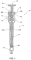
- syringe 10 comprises barrel 11 and plunger 20.
- Barrel 11 comprises needle end 13 to which is mountable a needle (not shown).
- Barrel 11 also comprises flared end 14 at which are located paired finger grips 15 and locating slots 16 in which is mounted barrel-engaging shoulders 45A, 45B of outer member 40.
- Inner member 50 is shown initially engaged with outer member 40.
- Barrel 11 may be of any capacity, although preferably barrel 11 is suitable for a syringe of less than 1.0 mL capacity, for example a 0.5 mL syringe.
- Plunger 20 comprises rod 21 with button 22 operable by a user, and opposed ratchets 23A, 23B, each disposed longitudinally along plunger rod 21.
- each ratchet 23 comprises a plurality of steps 24.
- Each step 24 has deep shoulder 26 and shallow shoulder 27. There is also an inclined surface 25 intermediate adjacent steps 24.
- Plunger rod 21 further comprises opposed guide slots 28, each of which comprises ramped abutment 29 each comprising ramp 30 and ledge 33.
- Guide slots assist maintaining a correct orientation of plunger 20 in use, while ledges 33 prevent complete withdrawal of plunger 20 from barrel 11, as will be described in more detail hereinafter.
- Ramps 30 assist in assembling plunger 20 into barrel 11.
- Needle end 31 of plunger 20 comprises nub 32 which fits into seal 60, as can be more readily seen in FIG. 1 .
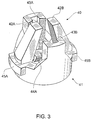
- outer member 40 comprises outer member body 41 having pawls 42A, 42B, channels 43A, 43B, fingers 44A, 44B and barrel-engaging shoulders 45A, 45B.
- Pawls 42A, 42B are resiliently deformable from an initial position where engagement with steps 24 is prevented to a position where pawls 42A, 42B can engage steps 24 to prevent, impede or otherwise hinder subsequent plunger 20 withdrawal, as will be described in more detail hereinafter.
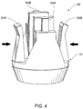
- inner member 50 comprises inner member body 51 having first projection 52A and second projection 52B, which projections are resiliently deformable in the direction indicated by arrows.
- Inner member body 51 also comprises tabs 54A, 54B.
- barrel-engaging shoulders 45A, 45B of outer member 40 fit into respective locating slots 16 of flared plunger end 14 of barrel 11 of syringe 10.
- Tabs 54A, 54B of inner member 50 are slidably located in channels 43A, 43B of outer member 40 (not shown). This aligns inner member 50 and outer member 40, preventing rotation therebetween. Alignment and non-rotation of plunger 20 is facilitated by fingers 44A, 44B of outer member 40 slidably engaging respective, opposed guide slots 28 on plunger rod 21 (not shown).
- first projection 52A and second projection 52B of inner member 50 are initially, respectively positioned between pawls 42A, 42B of outer member 40 and ratchets 23A, 23B, thereby preventing pawls 42A, 42B of collar contacting steps 24A, 24B.
- fingers 44A, 44B of outer member 40 slidably engage respective, opposed guide slots 28 on plunger rod 21, in use bear against ledges 33 if plunger 20 is withdrawn beyond a certain point to thereby prevent further plunger withdrawal. This prevents complete withdrawal of plunger 20 from barrel 11.
- pawls 42A, 42B do not appreciably interfere with depression of plunger 20 which provides a "smooth" feel to the user during delivery.
- pawls 42A, 42B respectively engage deep shoulders 26A, 26B of steps 24A, 24B in ratchets 23A, 23B to thereby prevent withdrawal of plunger 20 and re-use of syringe 10.
- the present invention provides a relatively simple, robust and inexpensive system for a syringe that is automatically disabled with little or no assistance from the user to thereby prevent, or at least minimize the likelihood of, re-use of the syringe.
- a mechanism for a syringe which can automatically disable the syringe and thereby prevent re-use of the syringe, which mechanism can be utilized with a non-retractable syringe needle.
- ratchets 23A, 23B need not be located at 180° with respect to each other, but may readily adopt different, relative positions on plunger 20 while performing the same function.
- the number of ratchets 23 and steps, teeth, ridges or abutments 24 that form the ratchet may be readily modified, as may be the number of pawls 42 on collar.
Landscapes
- Health & Medical Sciences (AREA)
- Vascular Medicine (AREA)
- Engineering & Computer Science (AREA)
- Anesthesiology (AREA)
- Biomedical Technology (AREA)
- Heart & Thoracic Surgery (AREA)
- Hematology (AREA)
- Life Sciences & Earth Sciences (AREA)
- Animal Behavior & Ethology (AREA)
- General Health & Medical Sciences (AREA)
- Public Health (AREA)
- Veterinary Medicine (AREA)
- Infusion, Injection, And Reservoir Apparatuses (AREA)
Description
- THIS INVENTION relates to syringes. More particularly, this invention relates to a syringe that includes an automatic mechanism to prevent or minimize the potential for re-use of the syringe.
- The practice of sharing syringes without adequate sterilization between successive users is a major contributor to the transfer of Human Immunodeficiency Virus (HIV), Hepatitis and other communicable diseases with subsequent severe repercussions for the sufferer and at a high cost to society for supporting and providing medical attention to sufferers.
- In response to this problem, syringes have been developed with the aim of preventing syringe re-use.
- One solution has been to develop syringes where the needle is permanently retractable into the barrel of the syringe, retraction driven by a compressed spring, as for example described in International Publication
WO 01/80930 - Although very effective, retractable syringes are relatively expensive, particularly when required in large quantities for mass immunizations or for distribution to intravenous drug users. This is particularly a problem in third world countries where the incidence of HIV is high, mass immunization programs need to be frequently undertaken and healthcare resources are limited.
-
United States Patent 6,494,863 describes a retractable syringe wherein the needle is retracted by release of a compressed spring in the needle assembly, the plunger having a single ratchet engageable by a single pawl only at the end of syringe use to thereby allow operation of the plunger during use but prevent withdrawal of the plunger and re-use of the syringe. - Several simpler and less expensive non-retractable syringe alternatives exist, such as syringes having disabling mechanisms that prevent re-use, but generally these syringes require the user to actively disable the syringe. Even health care professionals can at times be remiss and fail to actively disable such syringes after use.
- It is therefore an object of the invention to overcome or alleviate at least one of the deficiencies of the prior art, or at least provide a useful alternative.
- In one broad form there is provided a mechanism for a syringe which can automatically disable the syringe and thereby prevent re-use of the syringe, which mechanism is relatively simple and inexpensive to manufacture.
- The present disclosure in another broad form provides a mechanism for a syringe which can automatically disable the syringe and thereby prevent re-use of the syringe, which mechanism can preferably be utilized with a non-retractable syringe needle.
- There is described a plunger for a syringe having at least one pawl for engaging said plunger, said plunger comprising at least one longitudinal ratchet capable of engaging said at least one pawl to thereby prevent withdrawal of said plunger during or following depression of said plunger.
- The invention provides a disabling system for a syringe in accordance with the appended Claim 1.
- There is further described a syringe comprising a plunger and a barrel having at least one pawl, said plunger comprising at least one longitudinal ratchet capable of engaging said at least one pawl to prevent withdrawal of said plunger during depression of said plunger.
- In a preferred example a syringe comprises:
- (i) a barrel that comprises two pawls; and
- (ii) a plunger comprising:
- (a) two opposed ratchets respectively engageable by said two pawls to prevent withdrawal of said plunger during or following depression of said plunger; and
- (b) two opposed guide slots;
- Also described is a method of operating a syringe having a plunger and at least one pawl engageable with said plunger, said method including the step of depressing said plunger from a first position at which said at least one pawl is not engageable with said plunger to a second position at which said at least one pawl is engageable with said plunger and thereby prevents withdrawal of said plunger.
- In a preferred embodiment of the system, said plunger comprises two opposed ratchets, each disposed longitudinally along said plunger.
- According to this embodiment, said collar comprises two pawls, each said pawl engageable with a respective said opposed ratchet to prevent withdrawal of said plunger during or following depression of said plunger.
- The longitudinal ratchet may comprise a plurality of aligned steps, teeth, abutments or ridges oriented relative to said one or more pawls so as to be capable of engaging said one or more pawls, in use to prevent, impede or otherwise hinder withdrawal of said plunger during or following depression of said plunger.
- Throughout this specification, unless otherwise indicated, "comprise", "comprises" and "comprising" are used inclusively rather than exclusively, so that a stated integer or group of integers may include one or more other non-stated integers or groups of integers.
- Non-limiting embodiments of the invention are described herein with reference to drawings wherein:
-
FIG. 1 is a perspective view of a longitudinal section through an embodiment of a syringe; -
FIG. 2 is a perspective view of an embodiment of a plunger; -
FIG. 3 is a perspective view of an embodiment of an outer member; -
FIG. 4 is a perspective view of an embodiment of an inner member; -
FIG. 5 is a plan view of a longitudinal section through an embodiment of a syringe during plunger withdrawal; and -
FIG. 6 is a plan view of a longitudinal section through an embodiment of a syringe during plunger depression. - Referring to
FIG. 1 ,syringe 10 comprisesbarrel 11 and plunger 20.Barrel 11 comprisesneedle end 13 to which is mountable a needle (not shown).Barrel 11 also comprises flaredend 14 at which are located pairedfinger grips 15 and locatingslots 16 in which is mounted barrel-engaging shoulders outer member 40.Inner member 50 is shown initially engaged withouter member 40.Barrel 11 may be of any capacity, although preferablybarrel 11 is suitable for a syringe of less than 1.0 mL capacity, for example a 0.5 mL syringe.Plunger 20 comprisesrod 21 withbutton 22 operable by a user, and opposedratchets plunger rod 21. - Referring to
FIG. 2 , eachratchet 23 comprises a plurality ofsteps 24. Eachstep 24 hasdeep shoulder 26 andshallow shoulder 27. There is also aninclined surface 25 intermediateadjacent steps 24. -
Plunger rod 21 further comprisesopposed guide slots 28, each of which comprises rampedabutment 29 each comprisingramp 30 andledge 33. Guide slots assist maintaining a correct orientation ofplunger 20 in use, while ledges 33 prevent complete withdrawal ofplunger 20 frombarrel 11, as will be described in more detail hereinafter.Ramps 30 assist in assemblingplunger 20 intobarrel 11. -
Needle end 31 ofplunger 20 comprisesnub 32 which fits intoseal 60, as can be more readily seen inFIG. 1 . - Referring now to
FIG 3 ,outer member 40 comprisesouter member body 41 havingpawls channels fingers 44A, 44B and barrel-engaging shoulders steps 24 is prevented to a position wherepawls steps 24 to prevent, impede or otherwise hindersubsequent plunger 20 withdrawal, as will be described in more detail hereinafter. - As can be seen in
FIG 4 ,inner member 50 comprisesinner member body 51 havingfirst projection 52A andsecond projection 52B, which projections are resiliently deformable in the direction indicated by arrows.Inner member body 51 also comprisestabs - With this in mind and with reference to
FIG. 5 , when assembled, barrel-engaging shoulders outer member 40 fit into respective locatingslots 16 of flaredplunger end 14 ofbarrel 11 ofsyringe 10.Tabs FIG. 4 ) are slidably located inchannels inner member 50 andouter member 40, preventing rotation therebetween. Alignment and non-rotation ofplunger 20 is facilitated byfingers 44A, 44B ofouter member 40 slidably engaging respective, opposedguide slots 28 on plunger rod 21 (not shown). - In this correctly aligned and non-rotatable configuration,
first projection 52A andsecond projection 52B ofinner member 50 are initially, respectively positioned betweenpawls outer member 40 andratchets pawls collar contacting steps - It can be seen that during withdrawal of
plunger 20 to fillbarrel 11,pawls projections projections projections respective steps - Referring to
FIG. 2 andFIG. 5 ,fingers 44A, 44B ofouter member 40 slidably engage respective, opposedguide slots 28 onplunger rod 21, in use bear againstledges 33 ifplunger 20 is withdrawn beyond a certain point to thereby prevent further plunger withdrawal. This prevents complete withdrawal ofplunger 20 frombarrel 11. - Referring to
FIG. 5 andFIG. 6 , upon depression ofplunger 20,projections shallow shoulders steps plunger 20. The force applied to plunger 20 by the user pushesshallow shoulders steps projections inner member 50 out of its initial position engaged withouter member 40 to thereby exposepawls FIG. 6 thatprojections - Referring again to
FIG. 6 , due to the respective orientations ofpawls outer member 40, the direction of inclined surfaces 25A, 25B and the relative shallowness ofshallow shoulders plunger 20 which provides a "smooth" feel to the user during delivery. However, should the user attempt to subsequently withdrawplunger 20 to re-fillsyringe 10,pawls deep shoulders steps ratchets plunger 20 and re-use ofsyringe 10. - In light of the foregoing it will be appreciated that the present invention provides a relatively simple, robust and inexpensive system for a syringe that is automatically disabled with little or no assistance from the user to thereby prevent, or at least minimize the likelihood of, re-use of the syringe.
- Furthermore, there isprovided a mechanism for a syringe which can automatically disable the syringe and thereby prevent re-use of the syringe, which mechanism can be utilized with a non-retractable syringe needle.
- Throughout the specification, the aim has been to describe the preferred embodiments of the invention without limiting the invention to any one embodiment or specific collection of features. Various changes and modifications may be made to the embodiments described and illustrated without departing from the present invention. In particular, opposed ratchets 23A, 23B need not be located at 180° with respect to each other, but may readily adopt different, relative positions on
plunger 20 while performing the same function. Furthermore, the number ofratchets 23 and steps, teeth, ridges orabutments 24 that form the ratchet may be readily modified, as may be the number of pawls 42 on collar.
Claims (14)
- A disabling system for a syringe (10), said disabling system comprising a plunger (20) having ratchets (23A, 23B) and a collar mountable to a barrel (11) of said syringe (10), wherein each ratchet (23A, 23B) comprises a plurality of steps (24A, 24B), said steps comprising deep shoulders (26A, 26B) and shallow shoulders (27A, 27B),
said collar comprising an inner member (50) and an outer member (40) having resiliently deformable pawls (42A, 42B) capable of engaging said corresponding ratchets (23A, 23B) when in a non-deformed position, said inner member (50) comprising an inner member body (51) having a first projection (52A) and a second projection (52B), which projections (52A, 52B) are resiliently deformable, whereby in a deformed position said resiliently deformable pawls (42A, 42B) exert an inward pressure on projections (52A, 52B) thereby clamping said projections (52A, 52B) in a deformed position to prevent engagement of said ratchets (23A, 23B) by said pawls (42A, 42B) until said plunger (20) is depressed so that it pushes the shallow shoulders (27A, 27B) of the steps (24A, 24B) against said projections (52A, 52B), thereby forcing the inner member (50) out of its initial position engaged with the outer member (40) to thereby expose the pawls (42A, 42B) such that said projections (52A, 52B) return to a non-deformed position which allows said pawls (42A, 42B) to adopt the non-deformed position and can engage said corresponding ratchets (23A, 23B) to prevent withdrawal of said plunger (20) and syringe (10) re-use. - The disabling system of Claim 1, wherein the plunger (20) comprises two opposed ratchets (23A, 23B), each disposed longitudinally along said plunger (20).
- The disabling system of Claim 2, wherein each of said two opposed ratchets (23A, 23B) are alignable relative to two pawls (42A, 42B) so as to be capable of engaging said two pawls (42A, 42B) to prevent withdrawal of said plunger (20) during or following depression of said plunger (20).
- The disabling system of Claim 3, wherein each of said two opposed ratchets (23A, 23B) comprise a plurality of aligned steps, teeth or abutments (24).
- The disabling system of Claim 1, wherein the inner member (50) and the outer member (40) are in use incapable of rotation relative to each other.
- The disabling system of Claim 5, wherein said outer member (40) comprises two fingers (44A, 44B) capable of slidably engaging respective, opposed guide slots (28) located on said plunger (20) to thereby prevent rotation of said plunger (20) relative to said collar.
- A syringe (10) comprising the disabling system of Claim 1 mounted to a barrel (11).
- The syringe (10) of Claim 7, wherein the collar comprises two pawls (42A, 42B.
- The syringe (10) of Claim 8, wherein the plunger (20) comprises two opposed ratchets (23A, 23B), each disposed longitudinally along said plunger (20).
- The syringe (10) of Claim 9, wherein said two opposed ratchets (23A, 23B) are respectively alignable with the two pawls (42A, 42B) so as to be capable of respectively engaging said pawls (42A, 42B), in use to prevent withdrawal of said plunger (20) during or following depression of said plunger (20).
- The syringe (10) of Claim 10, wherein each of said two opposed ratchets (23A, 23B) comprise a plurality of aligned steps, teeth or abutments (24).
- The syringe (10) of Claim 8, wherein the inner member (50) and the outer member (40) are incapable of rotation relative to each other.
- The syringe (10) of Claim 12, wherein said outer member (40) comprises two fingers (44A, 44B) that slidably engage respective, opposed guide slots (28) located on said plunger (20) to thereby prevent rotation of said plunger (20) relative to said collar.
- A method of operating the syringe (10) of Claim 7, said method including the step of depressing said plunger (20) from a first position at which said at least one pawl (42A, 42B) is not engageable with said plunger (20) to a second position at which said at least one pawl (42A, 42B) is engageable with said plunger (20) and thereby prevents withdrawal of said plunger (20).
Applications Claiming Priority (2)
| Application Number | Priority Date | Filing Date | Title |
|---|---|---|---|
| AU2004900363A AU2004900363A0 (en) | 2004-01-28 | Auto-disable syringe | |
| PCT/AU2005/000106 WO2005072797A1 (en) | 2004-01-28 | 2005-01-28 | One use syringe with ratchet on plunger and pawl on body |
Publications (3)
| Publication Number | Publication Date |
|---|---|
| EP1708770A1 EP1708770A1 (en) | 2006-10-11 |
| EP1708770A4 EP1708770A4 (en) | 2010-05-05 |
| EP1708770B1 true EP1708770B1 (en) | 2016-10-05 |
Family
ID=34812593
Family Applications (1)
| Application Number | Title | Priority Date | Filing Date |
|---|---|---|---|
| EP05700137.2A Expired - Lifetime EP1708770B1 (en) | 2004-01-28 | 2005-01-28 | One use syringe with ratchet on plunger and pawl on body |
Country Status (9)
| Country | Link |
|---|---|
| US (1) | US8052654B2 (en) |
| EP (1) | EP1708770B1 (en) |
| CN (1) | CN100574824C (en) |
| AU (1) | AU2005209013B2 (en) |
| CA (1) | CA2554427C (en) |
| MY (1) | MY138413A (en) |
| PT (1) | PT1708770T (en) |
| TW (1) | TWI282743B (en) |
| WO (1) | WO2005072797A1 (en) |
Families Citing this family (30)
| Publication number | Priority date | Publication date | Assignee | Title |
|---|---|---|---|---|
| CN101052430B (en) * | 2004-07-16 | 2010-10-13 | 尤尼特拉克特注射器公司 | Syringe needle sheath |
| CN100450560C (en) * | 2007-02-12 | 2009-01-14 | 林作钱 | Self-destroying insulin injector |
| WO2008128273A1 (en) * | 2007-04-24 | 2008-10-30 | Morgan Meditech Inc | Single use syringe |
| DE102008049638A1 (en) * | 2008-09-30 | 2010-04-15 | Tecpharma Licensing Ag | Injection device with exactly ascertainable piston rod |
| CN102271730B (en) | 2008-11-26 | 2014-08-27 | 贝克顿·迪金森公司 | Single-use self-disabling syringes |
| US9480799B2 (en) * | 2009-04-08 | 2016-11-01 | Stat Medical Devices, Inc. | Retractable needle assembly utilizing a standard interface and syringe utilizing the same |
| US8986249B2 (en) * | 2009-04-08 | 2015-03-24 | Stat Medical Devices, Inc. | Retractable needle assembly and syringe utilizing the same |
| US20110125130A1 (en) * | 2009-04-08 | 2011-05-26 | Stat Medical Devices, Inc. | Retractable needle assembly and syringe utilizing the same |
| US20110160613A1 (en) * | 2009-12-22 | 2011-06-30 | Stat Medical Devices, Inc. | Fluid collection/injection device having syringe sample container and method of making and using the same |
| AU2010336003B2 (en) * | 2009-12-22 | 2014-07-03 | Unitract Syringe Pty Ltd | Retractable syringe with improved delivery efficiency and locking system |
| JP6290625B2 (en) | 2011-01-17 | 2018-03-07 | アクティヴパック, インコーポレイテッド | Aseptic cartridge and dispensing device |
| RU2457869C1 (en) * | 2011-06-22 | 2012-08-10 | Федеральное государственное учреждение "Межотраслевой научно-технический комплекс "Микрохирургия глаза" имени академика С.Н. Федорова Федерального агентства по высокотехнологичной медицинской помощи" | Dispenser device |
| PT2734255T (en) | 2011-08-24 | 2016-07-15 | Unitract Syringe Pty Ltd | Auto-injector for retractable prefilled syringe |
| US9078978B2 (en) | 2011-12-28 | 2015-07-14 | Stat Medical Devices, Inc. | Needle assembly with safety system for a syringe or fluid sampling device and method of making and using the same |
| CA2862880C (en) | 2012-02-06 | 2020-04-07 | Unitract Syringe Pty Ltd | Plunger sub-assemblies and auto-injectors having low retraction activation force |
| JP6177767B2 (en) * | 2012-04-24 | 2017-08-09 | テルモ株式会社 | Syringes and fittings |
| HK1209072A1 (en) | 2012-07-05 | 2016-03-24 | Unitract Syringe Pty Ltd | Automatic injectors for injectable cartridges and drive control mechanisms therefor |
| BR112015017599A2 (en) * | 2013-01-30 | 2017-10-03 | Terrence Armstrong Sean | SYRINGE |
| US9750885B2 (en) | 2013-05-01 | 2017-09-05 | Unl Holdings Llc | Plunger-driven auto-injectors |
| USD764657S1 (en) | 2013-07-03 | 2016-08-23 | Unitract Syringe Pty Ltd | Automatic injector |
| CA2920835A1 (en) | 2013-08-20 | 2015-02-26 | Anutra Medical, Inc. | Syringe fill system and method |
| EP3185933B1 (en) | 2014-08-28 | 2020-08-19 | UNL Holdings LLC | Sensor systems for drug delivery devices |
| JP2017525507A (en) | 2014-08-28 | 2017-09-07 | ユニトラクト シリンジ プロプライエタリイ リミテッドUnitract Syringe Pty Ltd | Skin detection system for drug delivery devices |
| CN105031772B (en) * | 2015-08-19 | 2018-11-27 | 江西丰临医疗科技股份有限公司 | Single-use auto-disable syringe |
| IT201800005604A1 (en) * | 2018-05-22 | 2018-08-22 | SAFETY AND FILLING SYSTEM FOR RETRACTABLE NEEDLE SYRINGES | |
| US10391517B1 (en) * | 2018-05-30 | 2019-08-27 | Sulzer Mixpac Ag | Dispenser assembly |
| WO2019233546A1 (en) * | 2018-06-04 | 2019-12-12 | Gemü Gmbh | Applicator |
| JP7412347B2 (en) * | 2018-10-24 | 2024-01-12 | 株式会社サーキュラス | Injection systems, syringes, and gaskets |
| CN112604067B (en) * | 2020-12-07 | 2022-08-05 | 湖南慧泽生物医药科技有限公司 | Cassette bottle injection box and methotrexate injection packaged by same |
| FR3119546B1 (en) * | 2021-02-09 | 2026-04-03 | Aptar France Sas | Microneedle applicator |
Family Cites Families (17)
| Publication number | Priority date | Publication date | Assignee | Title |
|---|---|---|---|---|
| JPS6130699U (en) * | 1984-07-26 | 1986-02-24 | 三菱鉛筆株式会社 | syringe |
| GB2203047B (en) * | 1987-02-27 | 1991-01-30 | Gilbert Henry Banks | Single-use syringe |
| DE8804656U1 (en) * | 1988-04-08 | 1988-08-04 | Bader, Mohandes, 2350 Neumünster | Medical syringe |
| US4950163A (en) * | 1988-05-19 | 1990-08-21 | Zimble Alan W | Dental syringe for treating gums |
| FR2633186A1 (en) | 1988-06-22 | 1989-12-29 | Court Jean | SINGLE-USE HYPODERMIC SYRINGE |
| FR2639832A1 (en) | 1988-12-05 | 1990-06-08 | Tredoulat Rene | Injection syringe which can be used only once |
| WO1990011790A1 (en) | 1989-04-04 | 1990-10-18 | Keith Herd Youne Mcmahon | Disposable syringe |
| US5084017A (en) * | 1989-10-10 | 1992-01-28 | John Maffetone | Self disabling, single use, hypodermic syringe |
| ES2031756A6 (en) | 1991-02-05 | 1992-12-16 | Gutierrez De Cepeda Juan | Syringe which can be used only once |
| US5380295A (en) * | 1992-12-14 | 1995-01-10 | Mallinckrodt Medical, Inc. | Delivery apparatus with mechanism preventing rearward movement of a piston disposed therein |
| US5328476A (en) * | 1993-08-23 | 1994-07-12 | Bidwell James K | One-time use hypodermic syringe apparatus and operation thereof |
| US5562623A (en) * | 1994-02-14 | 1996-10-08 | Univec | Single-use syringe assembly including spring clip lock and plunger |
| CN1224362A (en) * | 1996-05-09 | 1999-07-28 | 犹尼韦克股份有限公司 | Single use syringe with suction mechanism |
| US6533756B2 (en) * | 2000-02-10 | 2003-03-18 | Univec, Inc. | Single use syringe |
| US6494863B1 (en) * | 2001-10-15 | 2002-12-17 | Retractable Technologies, Inc. | One-use retracting syringe with positive needle retention |
| CN2546044Y (en) * | 2002-04-28 | 2003-04-23 | 山东威高集团有限公司 | Self-destroy injector |
| US7331934B2 (en) * | 2003-07-30 | 2008-02-19 | Becton Dickinson Co | Syringe assembly having disabling mechanism |
-
2005
- 2005-01-28 WO PCT/AU2005/000106 patent/WO2005072797A1/en not_active Ceased
- 2005-01-28 CA CA2554427A patent/CA2554427C/en not_active Expired - Fee Related
- 2005-01-28 AU AU2005209013A patent/AU2005209013B2/en not_active Ceased
- 2005-01-28 EP EP05700137.2A patent/EP1708770B1/en not_active Expired - Lifetime
- 2005-01-28 PT PT57001372T patent/PT1708770T/en unknown
- 2005-01-28 US US10/587,782 patent/US8052654B2/en active Active
- 2005-01-28 MY MYPI20050356A patent/MY138413A/en unknown
- 2005-01-28 CN CN200580006089A patent/CN100574824C/en not_active Expired - Fee Related
- 2005-01-28 TW TW094102605A patent/TWI282743B/en not_active IP Right Cessation
Also Published As
| Publication number | Publication date |
|---|---|
| PT1708770T (en) | 2017-01-09 |
| MY138413A (en) | 2009-06-30 |
| CN1933863A (en) | 2007-03-21 |
| EP1708770A4 (en) | 2010-05-05 |
| CA2554427C (en) | 2013-04-09 |
| US20080208143A1 (en) | 2008-08-28 |
| WO2005072797A1 (en) | 2005-08-11 |
| AU2005209013A1 (en) | 2005-08-11 |
| AU2005209013B2 (en) | 2009-11-26 |
| CN100574824C (en) | 2009-12-30 |
| TWI282743B (en) | 2007-06-21 |
| TW200526292A (en) | 2005-08-16 |
| EP1708770A1 (en) | 2006-10-11 |
| US8052654B2 (en) | 2011-11-08 |
| CA2554427A1 (en) | 2005-08-11 |
Similar Documents
| Publication | Publication Date | Title |
|---|---|---|
| CA2554427C (en) | One use syringe with ratchet on plunger and pawl on body | |
| US11541190B2 (en) | Palm activated drug delivery device | |
| AU2019202995B2 (en) | Palm activated drug delivery device | |
| AU2002367591B2 (en) | One-Use retracting syringe with positive needle retention | |
| US8734393B2 (en) | Autoinjector | |
| JP5997135B2 (en) | Syringe barrel adapter and needle assembly | |
| EP2217308B1 (en) | Autoinjector with container retaining means deactivatable by a safety shield | |
| CN100435873C (en) | Spring-launched needle safety clip | |
| EP0581822B1 (en) | A syringe | |
| EP1725279B1 (en) | Single use retractable syringe | |
| US20130060202A1 (en) | Clinical Syringe with Replaceable Retractable Needle | |
| CN105188807A (en) | Medicament delivery device comprising a locking mechanism | |
| JP6511653B2 (en) | Retainer for retractable needle assembly and syringe | |
| JP4361962B1 (en) | Container / Syringe | |
| JP5323589B2 (en) | Container / Syringe | |
| EP1436021B1 (en) | Single use syringe and plunger rod locking device therefor | |
| KR20040090933A (en) | a safety injector structure | |
| MXPA00006064A (en) | Safety syringe | |
| NZ531615A (en) | One-use retracting syringe with positive needle retention |
Legal Events
| Date | Code | Title | Description |
|---|---|---|---|
| PUAI | Public reference made under article 153(3) epc to a published international application that has entered the european phase |
Free format text: ORIGINAL CODE: 0009012 |
|
| 17P | Request for examination filed |
Effective date: 20060802 |
|
| AK | Designated contracting states |
Kind code of ref document: A1 Designated state(s): AT BE BG CH CY CZ DE DK EE ES FI FR GB GR HU IE IS IT LI LT LU MC NL PL PT RO SE SI SK TR |
|
| DAX | Request for extension of the european patent (deleted) | ||
| A4 | Supplementary search report drawn up and despatched |
Effective date: 20100409 |
|
| RAP1 | Party data changed (applicant data changed or rights of an application transferred) |
Owner name: UNITRACT SYRINGE PTY LTD |
|
| 17Q | First examination report despatched |
Effective date: 20140620 |
|
| GRAP | Despatch of communication of intention to grant a patent |
Free format text: ORIGINAL CODE: EPIDOSNIGR1 |
|
| INTG | Intention to grant announced |
Effective date: 20160425 |
|
| GRAS | Grant fee paid |
Free format text: ORIGINAL CODE: EPIDOSNIGR3 |
|
| GRAA | (expected) grant |
Free format text: ORIGINAL CODE: 0009210 |
|
| AK | Designated contracting states |
Kind code of ref document: B1 Designated state(s): AT BE BG CH CY CZ DE DK EE ES FI FR GB GR HU IE IS IT LI LT LU MC NL PL PT RO SE SI SK TR |
|
| REG | Reference to a national code |
Ref country code: GB Ref legal event code: FG4D |
|
| REG | Reference to a national code |
Ref country code: CH Ref legal event code: EP |
|
| REG | Reference to a national code |
Ref country code: AT Ref legal event code: REF Ref document number: 834074 Country of ref document: AT Kind code of ref document: T Effective date: 20161015 |
|
| REG | Reference to a national code |
Ref country code: IE Ref legal event code: FG4D |
|
| REG | Reference to a national code |
Ref country code: DE Ref legal event code: R096 Ref document number: 602005050342 Country of ref document: DE |
|
| REG | Reference to a national code |
Ref country code: FR Ref legal event code: PLFP Year of fee payment: 13 |
|
| REG | Reference to a national code |
Ref country code: PT Ref legal event code: SC4A Ref document number: 1708770 Country of ref document: PT Date of ref document: 20170109 Kind code of ref document: T Free format text: AVAILABILITY OF NATIONAL TRANSLATION Effective date: 20170102 |
|
| REG | Reference to a national code |
Ref country code: NL Ref legal event code: MP Effective date: 20161005 |
|
| REG | Reference to a national code |
Ref country code: LT Ref legal event code: MG4D |
|
| REG | Reference to a national code |
Ref country code: AT Ref legal event code: MK05 Ref document number: 834074 Country of ref document: AT Kind code of ref document: T Effective date: 20161005 |
|
| PG25 | Lapsed in a contracting state [announced via postgrant information from national office to epo] |
Ref country code: SE Free format text: LAPSE BECAUSE OF FAILURE TO SUBMIT A TRANSLATION OF THE DESCRIPTION OR TO PAY THE FEE WITHIN THE PRESCRIBED TIME-LIMIT Effective date: 20161005 Ref country code: LT Free format text: LAPSE BECAUSE OF FAILURE TO SUBMIT A TRANSLATION OF THE DESCRIPTION OR TO PAY THE FEE WITHIN THE PRESCRIBED TIME-LIMIT Effective date: 20161005 Ref country code: GR Free format text: LAPSE BECAUSE OF FAILURE TO SUBMIT A TRANSLATION OF THE DESCRIPTION OR TO PAY THE FEE WITHIN THE PRESCRIBED TIME-LIMIT Effective date: 20170106 |
|
| PG25 | Lapsed in a contracting state [announced via postgrant information from national office to epo] |
Ref country code: NL Free format text: LAPSE BECAUSE OF FAILURE TO SUBMIT A TRANSLATION OF THE DESCRIPTION OR TO PAY THE FEE WITHIN THE PRESCRIBED TIME-LIMIT Effective date: 20161005 Ref country code: IS Free format text: LAPSE BECAUSE OF FAILURE TO SUBMIT A TRANSLATION OF THE DESCRIPTION OR TO PAY THE FEE WITHIN THE PRESCRIBED TIME-LIMIT Effective date: 20170205 Ref country code: PL Free format text: LAPSE BECAUSE OF FAILURE TO SUBMIT A TRANSLATION OF THE DESCRIPTION OR TO PAY THE FEE WITHIN THE PRESCRIBED TIME-LIMIT Effective date: 20161005 Ref country code: FI Free format text: LAPSE BECAUSE OF FAILURE TO SUBMIT A TRANSLATION OF THE DESCRIPTION OR TO PAY THE FEE WITHIN THE PRESCRIBED TIME-LIMIT Effective date: 20161005 Ref country code: ES Free format text: LAPSE BECAUSE OF FAILURE TO SUBMIT A TRANSLATION OF THE DESCRIPTION OR TO PAY THE FEE WITHIN THE PRESCRIBED TIME-LIMIT Effective date: 20161005 Ref country code: AT Free format text: LAPSE BECAUSE OF FAILURE TO SUBMIT A TRANSLATION OF THE DESCRIPTION OR TO PAY THE FEE WITHIN THE PRESCRIBED TIME-LIMIT Effective date: 20161005 Ref country code: BE Free format text: LAPSE BECAUSE OF FAILURE TO SUBMIT A TRANSLATION OF THE DESCRIPTION OR TO PAY THE FEE WITHIN THE PRESCRIBED TIME-LIMIT Effective date: 20161005 |
|
| REG | Reference to a national code |
Ref country code: DE Ref legal event code: R097 Ref document number: 602005050342 Country of ref document: DE |
|
| PG25 | Lapsed in a contracting state [announced via postgrant information from national office to epo] |
Ref country code: DK Free format text: LAPSE BECAUSE OF FAILURE TO SUBMIT A TRANSLATION OF THE DESCRIPTION OR TO PAY THE FEE WITHIN THE PRESCRIBED TIME-LIMIT Effective date: 20161005 Ref country code: SK Free format text: LAPSE BECAUSE OF FAILURE TO SUBMIT A TRANSLATION OF THE DESCRIPTION OR TO PAY THE FEE WITHIN THE PRESCRIBED TIME-LIMIT Effective date: 20161005 Ref country code: EE Free format text: LAPSE BECAUSE OF FAILURE TO SUBMIT A TRANSLATION OF THE DESCRIPTION OR TO PAY THE FEE WITHIN THE PRESCRIBED TIME-LIMIT Effective date: 20161005 Ref country code: CZ Free format text: LAPSE BECAUSE OF FAILURE TO SUBMIT A TRANSLATION OF THE DESCRIPTION OR TO PAY THE FEE WITHIN THE PRESCRIBED TIME-LIMIT Effective date: 20161005 Ref country code: RO Free format text: LAPSE BECAUSE OF FAILURE TO SUBMIT A TRANSLATION OF THE DESCRIPTION OR TO PAY THE FEE WITHIN THE PRESCRIBED TIME-LIMIT Effective date: 20161005 |
|
| PLBE | No opposition filed within time limit |
Free format text: ORIGINAL CODE: 0009261 |
|
| STAA | Information on the status of an ep patent application or granted ep patent |
Free format text: STATUS: NO OPPOSITION FILED WITHIN TIME LIMIT |
|
| PG25 | Lapsed in a contracting state [announced via postgrant information from national office to epo] |
Ref country code: BG Free format text: LAPSE BECAUSE OF FAILURE TO SUBMIT A TRANSLATION OF THE DESCRIPTION OR TO PAY THE FEE WITHIN THE PRESCRIBED TIME-LIMIT Effective date: 20170105 |
|
| REG | Reference to a national code |
Ref country code: CH Ref legal event code: PL |
|
| 26N | No opposition filed |
Effective date: 20170706 |
|
| PG25 | Lapsed in a contracting state [announced via postgrant information from national office to epo] |
Ref country code: MC Free format text: LAPSE BECAUSE OF FAILURE TO SUBMIT A TRANSLATION OF THE DESCRIPTION OR TO PAY THE FEE WITHIN THE PRESCRIBED TIME-LIMIT Effective date: 20161005 |
|
| PG25 | Lapsed in a contracting state [announced via postgrant information from national office to epo] |
Ref country code: CH Free format text: LAPSE BECAUSE OF NON-PAYMENT OF DUE FEES Effective date: 20170131 Ref country code: LI Free format text: LAPSE BECAUSE OF NON-PAYMENT OF DUE FEES Effective date: 20170131 |
|
| PG25 | Lapsed in a contracting state [announced via postgrant information from national office to epo] |
Ref country code: LU Free format text: LAPSE BECAUSE OF NON-PAYMENT OF DUE FEES Effective date: 20170128 Ref country code: SI Free format text: LAPSE BECAUSE OF FAILURE TO SUBMIT A TRANSLATION OF THE DESCRIPTION OR TO PAY THE FEE WITHIN THE PRESCRIBED TIME-LIMIT Effective date: 20161005 |
|
| REG | Reference to a national code |
Ref country code: FR Ref legal event code: PLFP Year of fee payment: 14 |
|
| PG25 | Lapsed in a contracting state [announced via postgrant information from national office to epo] |
Ref country code: HU Free format text: LAPSE BECAUSE OF FAILURE TO SUBMIT A TRANSLATION OF THE DESCRIPTION OR TO PAY THE FEE WITHIN THE PRESCRIBED TIME-LIMIT; INVALID AB INITIO Effective date: 20050128 |
|
| PG25 | Lapsed in a contracting state [announced via postgrant information from national office to epo] |
Ref country code: CY Free format text: LAPSE BECAUSE OF NON-PAYMENT OF DUE FEES Effective date: 20161005 |
|
| PGFP | Annual fee paid to national office [announced via postgrant information from national office to epo] |
Ref country code: FR Payment date: 20191230 Year of fee payment: 16 |
|
| PG25 | Lapsed in a contracting state [announced via postgrant information from national office to epo] |
Ref country code: TR Free format text: LAPSE BECAUSE OF FAILURE TO SUBMIT A TRANSLATION OF THE DESCRIPTION OR TO PAY THE FEE WITHIN THE PRESCRIBED TIME-LIMIT Effective date: 20161005 |
|
| PGFP | Annual fee paid to national office [announced via postgrant information from national office to epo] |
Ref country code: PT Payment date: 20200124 Year of fee payment: 16 Ref country code: IT Payment date: 20200114 Year of fee payment: 16 Ref country code: GB Payment date: 20200115 Year of fee payment: 16 Ref country code: IE Payment date: 20200109 Year of fee payment: 16 Ref country code: DE Payment date: 20200114 Year of fee payment: 16 |
|
| REG | Reference to a national code |
Ref country code: DE Ref legal event code: R119 Ref document number: 602005050342 Country of ref document: DE |
|
| GBPC | Gb: european patent ceased through non-payment of renewal fee |
Effective date: 20210128 |
|
| PG25 | Lapsed in a contracting state [announced via postgrant information from national office to epo] |
Ref country code: FR Free format text: LAPSE BECAUSE OF NON-PAYMENT OF DUE FEES Effective date: 20210131 |
|
| PG25 | Lapsed in a contracting state [announced via postgrant information from national office to epo] |
Ref country code: PT Free format text: LAPSE BECAUSE OF NON-PAYMENT OF DUE FEES Effective date: 20210728 Ref country code: DE Free format text: LAPSE BECAUSE OF NON-PAYMENT OF DUE FEES Effective date: 20210803 Ref country code: GB Free format text: LAPSE BECAUSE OF NON-PAYMENT OF DUE FEES Effective date: 20210128 |
|
| PG25 | Lapsed in a contracting state [announced via postgrant information from national office to epo] |
Ref country code: IE Free format text: LAPSE BECAUSE OF NON-PAYMENT OF DUE FEES Effective date: 20210128 |
|
| PG25 | Lapsed in a contracting state [announced via postgrant information from national office to epo] |
Ref country code: IT Free format text: LAPSE BECAUSE OF NON-PAYMENT OF DUE FEES Effective date: 20210128 |