EP1708481A2 - Two-dimensional gray component replacement - Google Patents
Two-dimensional gray component replacement Download PDFInfo
- Publication number
- EP1708481A2 EP1708481A2 EP06111898A EP06111898A EP1708481A2 EP 1708481 A2 EP1708481 A2 EP 1708481A2 EP 06111898 A EP06111898 A EP 06111898A EP 06111898 A EP06111898 A EP 06111898A EP 1708481 A2 EP1708481 A2 EP 1708481A2
- Authority
- EP
- European Patent Office
- Prior art keywords
- color
- value
- highlight
- likelihood
- pixel
- Prior art date
- Legal status (The legal status is an assumption and is not a legal conclusion. Google has not performed a legal analysis and makes no representation as to the accuracy of the status listed.)
- Granted
Links
Images


Classifications
-
- H—ELECTRICITY
- H04—ELECTRIC COMMUNICATION TECHNIQUE
- H04N—PICTORIAL COMMUNICATION, e.g. TELEVISION
- H04N1/00—Scanning, transmission or reproduction of documents or the like, e.g. facsimile transmission; Details thereof
- H04N1/46—Colour picture communication systems
- H04N1/56—Processing of colour picture signals
- H04N1/60—Colour correction or control
- H04N1/6016—Conversion to subtractive colour signals
- H04N1/6022—Generating a fourth subtractive colour signal, e.g. under colour removal, black masking
-
- G—PHYSICS
- G06—COMPUTING OR CALCULATING; COUNTING
- G06T—IMAGE DATA PROCESSING OR GENERATION, IN GENERAL
- G06T1/00—General purpose image data processing
-
- G—PHYSICS
- G06—COMPUTING OR CALCULATING; COUNTING
- G06T—IMAGE DATA PROCESSING OR GENERATION, IN GENERAL
- G06T11/00—Two-dimensional [2D] image generation
-
- H—ELECTRICITY
- H04—ELECTRIC COMMUNICATION TECHNIQUE
- H04N—PICTORIAL COMMUNICATION, e.g. TELEVISION
- H04N1/00—Scanning, transmission or reproduction of documents or the like, e.g. facsimile transmission; Details thereof
- H04N1/46—Colour picture communication systems
- H04N1/56—Processing of colour picture signals
- H04N1/60—Colour correction or control
- H04N1/62—Retouching, i.e. modification of isolated colours only or in isolated picture areas only
Definitions
- a picture element may be defined as a space on a page into which dots of ink, dye or toner are placed.
- the placing and number of the dots determines how a human eye integrates the dots and picture elements into an image.
- Colors of pixels are generally controlled by the number of dots of different colors of ink within the space.
- a pixel having a high concentration of yellow dots will appear mostly yellow. The yellow can be altered to appear greener or more orange by the addition of dots of the other colors.
- color imaging processes use subtractive coloring to achieve color images.
- the substrate upon which an image is displayed the screen
- the substrate is generally considered to be black and colors are added together to form color images.
- the substrate is generally white, so colors are added together to subtract color from white.
- the subtractive colors are cyan, magenta and yellow (CMY).
- the dyes In dye-based color printing systems, the dyes have high purity and intensity and the color black may be recreated on the paper by mixing the three colors together. In ink and toner-based systems, however, that is not usually the case. The mix of CMY generally results in an intermediate brownish color, not black. Therefore, black is added to the available inks and toners, and is represented by the color K.
- GCR gray component replacement
- UCR under color removal
- the one-dimensional GCR process may result in objectionable artifacts in the final output hardcopy, such as graininess in highlight areas, color fringing, texture contouring, edge blurring, and reducing of color in dark areas.
- One embodiment is a method of gray component replacement.
- a current pixel color value is received.
- a highlight likelihood and a color neutrality are determined for the current color pixel value.
- An output color pixel value is then generated depending upon the color neutrality and the highlight likelihood.
- the determining the color neutrality, the highlight likelihood and generating the highlight likelihood further comprises real-time calculations.
- the imaging system has an image acquisition engine, an image processing module that performs gray component replacement and an output engine.
- the system further comprises a memory.
- the memory further comprises a look-up table used by the processing module to generate the output color pixel value.
- the imaging system further comprises a multi-function peripheral.
- the output engine further comprises a xerographic print engine.
- the image acquisition engine further comprises one selected from the group consisting of: a scanner, a connection to a host computer, a data network connection, and a fax receiver.
- the article further contains instructions that, when executed, cause the computer to set an input mode.
- the instructions cause the computer to generate an output pixel color value further causing the computer to generate an output pixel color value depending upon the input mode. In a further embodiment the instructions cause the computer to generate an output pixel color further comprising instructions causing the computer to access a look-up table to obtain the output pixel color value. In a further embodiment the instructions causes the computer to determine highlight likelihood, color neutrality, and generate an output pixel color value further cause the computer to determine highlight likelihood, color neutrality and generate an output pixel color value in real time.
- Figure 1 shows an embodiment of an image acquisition system.
- Figure 2 shows an embodiment of an image processing module performing color conversion with gray component replacement.
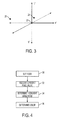
- Figure 3 shows an example of a color space axis.
- Figure 4 shows a flowchart of an embodiment of a method to perform gray component replacement.
- Figure 5 shows a graphical representation of a function to control black generation in a direction from saturated color to neutral color axis.
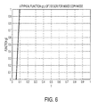
- Figure 6 shows a graphical representation of a function to control black subtraction in a direction from highlight to shadow along neutral axis.
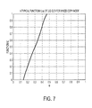
- Figure 7 shows a graphical representation of a function to control black subtraction in a direction from saturated color to neutral color axis.
- FIG. 1 shows an embodiment of an imaging system 10.
- the imaging system has an image acquisition engine 12 that acquires data representative of an image.
- This engine could be a scanner, such as would be on a copy or fax machine.
- the image data would be acquired by the scanning of a pre-existing document to capture the image data.
- the scanning may be from a glass platen, such as from a copy machine, or a light bar, such as from a fax machine.
- the image may be acquired by from a host computer upon which a user has created an original document.
- This host computer may be directly connected to the device holding the print system, or it may access the device from a data network.
- the image acquisition may be from an incoming fax, at a fax receiver across a telephone line. However acquired, the image acquisition engine receives the image data.
- the acquired image data is then routed to an image processing module 14.
- Image processing takes the acquired image values and performs the necessary processing to allow the data to be sent to an output engine for rendering. This may involved color space conversion, such as when the image acquisition engine acquires the image data in the RedGreen-Blue (RGB) or L*a*b color space, and the output engine functions in the Cyan-Yellow-Magenta-Black (CMYK) color space.
- Color conversion module 16 may be a dedicated portion of the image processing module, such as a portion of an application specific integrated circuit or a processor, or part of a process running on an image processor.
- the color conversion module may be implemented in hardware, or as a part of the overall image processing operations.
- the refined image data in the form of pixel color values is sent to the output engine 20.
- the data may be temporarily stored in various stages during the processing in the memory 18.
- the memory may contain look-up tables and/or registers.
- the output engine 20 may be one of several different engines capable of rendering an image from the image data.
- the output engine is a print engine that renders the image onto paper or other printing substrate via ink, dyes or toner.
- a print engine is an electrophotographic print engine, also known as a xerographic print engine.
- Other examples of output engines could be graphics adapters, such as when faxes are converted to electronic mail and routed from a fax server to a user's desktop as images, or the output engine could write the data to a file.
- gray component replacement typically involves altering the color values of pixels to account for the addition of black ink, or manipulating the values of black to account for varying levels of color in certain areas.
- the color conversion module_ may actually be a process running on the image processor 14.
- the memory 162 shown in Figure 2 may be a partition or other segment of the main memory 18 of Figure 1.
- the current pixel value from the image processing module may be stored in an input register 164.
- the processor 160 then processes the current pixel value to produce the output pixel value.
- the production of the output pixel value may involve the use of look-up table 166, as will be discussed with regard to Figures 3 and 4.
- the color conversion process in performing gray component replacement, may define three functions with regard to the location of the current pixel color value with regard to the neutral gray axis.
- Figure 3 shows an example of a color space as defined by the L*a*b* axes.
- L* is the luminance or color intensity
- a* is the red/green axis
- b* is the yellow/blue axis.
- the point 22 is at the 'origin' or the neutral color point.
- Point 24 is close to the neutral gray axis, while point 26 is farther away from the neutral gray axis than the point 24.
- the color conversion process manipulates the output color pixel values to account for the location of the pixel to the neutral axis as the black component, K, is added to the output pixel color value.
- An embodiment of this process is shown in Figure 4.
- the determination of the output pixel color values may be affected by the mode of the scanning and rending system. For example, the output color pixel values may shift if the device is in text only, graphics only, photographic only, or 'mixed' mode, a blend of the three modes. This mode is 'set' at 30. Setting the mode may be done by a user, or may be determined by the device based upon a profile of the acquired image data. For purposes of this discussion, the mixed mode will be assumed.
- the current pixel color value is received. This is done through the image acquisition module discussed above and may involve the image processing module and the color conversion module, where the GCR process is performed.
- the first direction is from highlight to mid-tone to shadow areas.
- the second direction is from the neutral axis to the intermediate colorful area to saturated color.
- Two characteristic quantities may be defined, one to indicate the likelihood of a pixel being in a highlight region, ⁇ , and one to indicate how neutral a color is, ⁇ .
- the highlight likelihood is the average of percent coverage of input CMY components of the current pixel color value, where the current pixel color value is (C i , M i , Y i ).
- the highlight likelihood is an inverse of the quantity ⁇ .
- the highlight likelihood of the current pixel color value is determined at 34.
- the color neutrality is defined as the ratio of the minimum of the color components CMY for the current pixel color value to the maximum of the color components for the current pixel color value.
- the output color pixel values are C o , M o ,Y o , K o .
- the functions f() and h() operate on the variable ⁇ .
- the function f() controls the black generation in the direction from the neutral axis through the intermediate color area to saturated color.
- the function h() controls the color subtraction necessary to account for the black addition, mentioned above, in the direction from the neutral axis towards saturated color.
- the function g() operates on the highlight likelihood variable to control black subtraction in the direction highlight through mid-tone to shadow areas. Black subtraction is necessary in highlight areas to avoid graininess.
- f() The particular function used for f() is left up to the system designer, but there are some characteristics and considerations that may be useful.
- the function has a region where the variable is so small there is no black colorant used to render the more saturated color. This enlarges the color gamut and makes the more saturated colors less grainy.
- ⁇ becomes greater than a certain value ⁇ 1
- f() smoothly transitions to a value of 1 through the intermediate colorful region.
- the smoothness of transition avoids color contouring.
- the value of 1 is reached for f() at ⁇ 2 , it remains at 1 to enforce a maximum black strategy for the color around the neutral gray axis. This avoids color fringing artifacts in black/white text edge rendering. By eliminating color dots around the black/white edges, black/white text is reproduced with sharp edge definition using maximum black dots in the mixed mode.
- a graphical representation of the function g() is shown in Figure 6.
- the zero region when the quantity ⁇ is small reduces the occurrence of black dots in these areas, reducing the graininess.
- Scanners cannot generally capture a perfect, sharp edge of black/white texts in an original. After applying background suppression, where any color or black occurring in a region deemed to be the background is removed, there is still a pixel transition zone from light gray pixel levels at the white to dark transition and dark gray pixel levels at the dark portion of the text around the scanned text edge. If a scanner has a highly accurate modulation transfer function, the zero interval can be longer. After ⁇ reaches a level ⁇ 1 , the function needs to transition quickly to the maximum value of 1 to avoid color fringing artifacts in the black/white text edges. The potential color-contouring artifacts are generally avoided, since the multiplication of f() and g() ultimately controls black generation.
- a graphical representation of the function h() is shown in Figure 7.
- the function h() controls the color subtraction of the GCR process. It is normally a monotonically non-decreasing function of variable ⁇ .
- a typical curve starts from 0 to maintain the color gamut as large as possible. It then rises smoothly to a maximum value of 1. It would not be unusual for the curve to have a zero value zone to preserve saturated dark color areas, or to have a clipped zone of value one to control the overall ink coverage. For some unusually low total area coverage (TAC) constraints, one may also want to use constant value h() to better meet the TAC constraint.
- TAC total area coverage
- this particular example was for the mixed mode of a combination of text, graphics and photographic images.
- photographic mode there is no concern about color fringing about the black/white edges of text.
- the f() curve can be pushed to the right, extending the zero value region and reducing the 1 region. The same would apply to g() and h() in the photographic mode.
- the maximum black strategy should be implemented to encourage black dot filling to render edges more sharply. This may be accomplished by setting all three functions to 1.
- these functions and variables are used to determine the output pixel color value at 38.
- the actual implementation of these determinations may vary depending upon the system design and requirements.
- the determinations may be predetermined and stored in one or more look-up tables, as shown in Figure 2.
- the current pixel color values of CMY could be used as an index into the look-up table for ⁇ , the highlight likelihood, and a preliminary determination of the max and min used to index into a look-up table for ⁇ , the color neutrality.
- These values could then be used as an index into look-up tables for the values of f(), g() and that used to calculate the value for K o .
- the combination of these values could then be used to index into look-up tables for the color components.
- the entire calculation could be performed in real-time, 'on the fly.'
- some of the calculations could be performed in real-time, with the results being used to index into various look-up tables.
- the variables could be obtained from a look-up table and used to calculate the values in real-time.
- an article of computer-readable media such as an electronic file, diskette, compact disc or firmware loaded into a processor may contain instructions that, when executed, cause a computer to perform the methods discussed above.
- the computer may be a multi-function peripheral, a fax machine, a printer, a copier, etc.
- the processor upon which the instructions are loaded may be a field-programmable gate array (FPGA), application specific integrated circuit (ASIC), etc.
- the gray component replacement process may be implemented in two dimensions, instead of just one. This results in higher-quality rendered images, with reduced objectionable artifacts.
- the process is flexible to be adjusted to different modes and systems with different modulation transfer functions and other characteristics.
Landscapes
- Engineering & Computer Science (AREA)
- Multimedia (AREA)
- Signal Processing (AREA)
- Physics & Mathematics (AREA)
- General Physics & Mathematics (AREA)
- Theoretical Computer Science (AREA)
- Image Processing (AREA)
- Facsimile Image Signal Circuits (AREA)
- Color Image Communication Systems (AREA)
- Color, Gradation (AREA)
Abstract
Description
- In digital printing systems, a picture element (pixel) may be defined as a space on a page into which dots of ink, dye or toner are placed. The placing and number of the dots determines how a human eye integrates the dots and picture elements into an image. Colors of pixels, for example, are generally controlled by the number of dots of different colors of ink within the space. A pixel having a high concentration of yellow dots will appear mostly yellow. The yellow can be altered to appear greener or more orange by the addition of dots of the other colors.
- Generally, color imaging processes use subtractive coloring to achieve color images. In digital display systems, the substrate upon which an image is displayed, the screen, is generally considered to be black and colors are added together to form color images. In digital printing, the substrate is generally white, so colors are added together to subtract color from white. The subtractive colors are cyan, magenta and yellow (CMY).
- In dye-based color printing systems, the dyes have high purity and intensity and the color black may be recreated on the paper by mixing the three colors together. In ink and toner-based systems, however, that is not usually the case. The mix of CMY generally results in an intermediate brownish color, not black. Therefore, black is added to the available inks and toners, and is represented by the color K.
- When an image is produced using CMYK, the addition of black requires that the other color amounts be altered to account for the addition. This process is generally referred to as gray component replacement (GCR) or under color removal (UCR). Most GCR systems rely upon a series of equations that are applied to the current CMYK values of a given pixel. These equations generally only use the minimum value of the CMY values for the current pixel. This may be thought of as performing a one-dimensional GCR process.
- For print mode, this one-dimensional method of GCR seems sufficient for the most applications. However, for such applications as the copy mode of multi-function device, where the electronic scan image is a mix of text, pictorial and graphic contents, the one-dimensional GCR process may result in objectionable artifacts in the final output hardcopy, such as graininess in highlight areas, color fringing, texture contouring, edge blurring, and reducing of color in dark areas.
- One embodiment is a method of gray component replacement. A current pixel color value is received. A highlight likelihood and a color neutrality are determined for the current color pixel value. An output color pixel value is then generated depending upon the color neutrality and the highlight likelihood.
In a further embodiment, the determining the color neutrality, the highlight likelihood and generating the highlight likelihood further comprises real-time calculations. - Another embodiment is an imaging system. The imaging system has an image acquisition engine, an image processing module that performs gray component replacement and an output engine.
In a further embodiment the system further comprises a memory.
In a further embodiment the memory further comprises a look-up table used by the processing module to generate the output color pixel value.
In a further embodiment the imaging system further comprises a multi-function peripheral.
In a further embodiment the output engine further comprises a xerographic print engine.
In a further embodiment the image acquisition engine further comprises one selected from the group consisting of: a scanner, a connection to a host computer, a data network connection, and a fax receiver.
In one embodiment of the article ofclaim 10, the article further contains instructions that, when executed, cause the computer to set an input mode.
In a further embodiment the instructions cause the computer to generate an output pixel color value further causing the computer to generate an output pixel color value depending upon the input mode.
In a further embodiment the instructions cause the computer to generate an output pixel color further comprising instructions causing the computer to access a look-up table to obtain the output pixel color value.
In a further embodiment the instructions causes the computer to determine highlight likelihood, color neutrality, and generate an output pixel color value further cause the computer to determine highlight likelihood, color neutrality and generate an output pixel color value in real time. - Figure 1 shows an embodiment of an image acquisition system.
- Figure 2 shows an embodiment of an image processing module performing color conversion with gray component replacement.
- Figure 3 shows an example of a color space axis.
- Figure 4 shows a flowchart of an embodiment of a method to perform gray component replacement.
- Figure 5 shows a graphical representation of a function to control black generation in a direction from saturated color to neutral color axis.
- Figure 6 shows a graphical representation of a function to control black subtraction in a direction from highlight to shadow along neutral axis.
- Figure 7 shows a graphical representation of a function to control black subtraction in a direction from saturated color to neutral color axis.
- Figure 1 shows an embodiment of an
imaging system 10. The imaging system has animage acquisition engine 12 that acquires data representative of an image. This engine could be a scanner, such as would be on a copy or fax machine. The image data would be acquired by the scanning of a pre-existing document to capture the image data. The scanning may be from a glass platen, such as from a copy machine, or a light bar, such as from a fax machine. - In addition to, or in the alternative of, a scanning platen or light bar, the image may be acquired by from a host computer upon which a user has created an original document. This host computer may be directly connected to the device holding the print system, or it may access the device from a data network. In addition, the image acquisition may be from an incoming fax, at a fax receiver across a telephone line. However acquired, the image acquisition engine receives the image data.
- The acquired image data is then routed to an
image processing module 14. Image processing takes the acquired image values and performs the necessary processing to allow the data to be sent to an output engine for rendering. This may involved color space conversion, such as when the image acquisition engine acquires the image data in the RedGreen-Blue (RGB) or L*a*b color space, and the output engine functions in the Cyan-Yellow-Magenta-Black (CMYK) color space. - It is generally part of this color conversion process that the gray component replacement (GCR) process is performed.
Color conversion module 16 may be a dedicated portion of the image processing module, such as a portion of an application specific integrated circuit or a processor, or part of a process running on an image processor. The color conversion module may be implemented in hardware, or as a part of the overall image processing operations. - After image processing, the refined image data in the form of pixel color values is sent to the
output engine 20. During this process, the data may be temporarily stored in various stages during the processing in thememory 18. As will be discussed further, the memory may contain look-up tables and/or registers. - The
output engine 20 may be one of several different engines capable of rendering an image from the image data. In one embodiment the output engine is a print engine that renders the image onto paper or other printing substrate via ink, dyes or toner. One such example of a print engine is an electrophotographic print engine, also known as a xerographic print engine. Other examples of output engines could be graphics adapters, such as when faxes are converted to electronic mail and routed from a fax server to a user's desktop as images, or the output engine could write the data to a file. - As mentioned above, gray component replacement typically involves altering the color values of pixels to account for the addition of black ink, or manipulating the values of black to account for varying levels of color in certain areas. As mentioned above, the color conversion module_may actually be a process running on the
image processor 14. - In addition, the
memory 162 shown in Figure 2 may be a partition or other segment of themain memory 18 of Figure 1. The current pixel value from the image processing module may be stored in aninput register 164. Theprocessor 160 then processes the current pixel value to produce the output pixel value. The production of the output pixel value may involve the use of look-up table 166, as will be discussed with regard to Figures 3 and 4. - The color conversion process, in performing gray component replacement, may define three functions with regard to the location of the current pixel color value with regard to the neutral gray axis. Figure 3 shows an example of a color space as defined by the L*a*b* axes. L* is the luminance or color intensity, a* is the red/green axis, and b* is the yellow/blue axis. The
point 22 is at the 'origin' or the neutral color point. Point 24 is close to the neutral gray axis, whilepoint 26 is farther away from the neutral gray axis than the point 24. - The color conversion process manipulates the output color pixel values to account for the location of the pixel to the neutral axis as the black component, K, is added to the output pixel color value. An embodiment of this process is shown in Figure 4. As will be discussed in more detail further, the determination of the output pixel color values may be affected by the mode of the scanning and rending system. For example, the output color pixel values may shift if the device is in text only, graphics only, photographic only, or 'mixed' mode, a blend of the three modes. This mode is 'set' at 30. Setting the mode may be done by a user, or may be determined by the device based upon a profile of the acquired image data. For purposes of this discussion, the mixed mode will be assumed.
- At 32, the current pixel color value is received. This is done through the image acquisition module discussed above and may involve the image processing module and the color conversion module, where the GCR process is performed.
- It is possible to impose controls over the GCR process in two directions. The first direction is from highlight to mid-tone to shadow areas. The second direction is from the neutral axis to the intermediate colorful area to saturated color. Two characteristic quantities may be defined, one to indicate the likelihood of a pixel being in a highlight region, γ, and one to indicate how neutral a color is, φ.
- The highlight likelihood is the average of percent coverage of input CMY components of the current pixel color value, where the current pixel color value is (Ci, Mi, Yi). The quantity γ is defined as:

- The less γ, the less ink coverage there is, the more likely the color belongs to a highlight region. Generally, then, the highlight likelihood is an inverse of the quantity γ. The highlight likelihood of the current pixel color value is determined at 34.
- The color neutrality is defined as the ratio of the minimum of the color components CMY for the current pixel color value to the maximum of the color components for the current pixel color value. The color neutrality for the current pixel color value is determined at 36.


- Having defined these quantities, it is possible to develop a GCR process using the following formulations.




- The output color pixel values are Co, Mo ,Yo, Ko. As discussed above, the output color components CMY need to be adjusted to account for the addition of the output black value Ko. The functions f() and h() operate on the variable φ. The function f() controls the black generation in the direction from the neutral axis through the intermediate color area to saturated color. The function h() controls the color subtraction necessary to account for the black addition, mentioned above, in the direction from the neutral axis towards saturated color. The function g() operates on the highlight likelihood variable to control black subtraction in the direction highlight through mid-tone to shadow areas. Black subtraction is necessary in highlight areas to avoid graininess. These functions are user-generated and may be defined in many different ways. A graphical representation of the function f() is shown in Figure 5.
- The particular function used for f() is left up to the system designer, but there are some characteristics and considerations that may be useful. The function has a region where the variable is so small there is no black colorant used to render the more saturated color. This enlarges the color gamut and makes the more saturated colors less grainy. After φ becomes greater than a certain value φ 1, f() smoothly transitions to a value of 1 through the intermediate colorful region. The smoothness of transition avoids color contouring. After the value of 1 is reached for f() at φ 2, it remains at 1 to enforce a maximum black strategy for the color around the neutral gray axis. This avoids color fringing artifacts in black/white text edge rendering. By eliminating color dots around the black/white edges, black/white text is reproduced with sharp edge definition using maximum black dots in the mixed mode.
- A graphical representation of the function g() is shown in Figure 6. The zero region when the quantity γ is small reduces the occurrence of black dots in these areas, reducing the graininess. Generally, the longer the function g() stays at zero, the better the resulting image. However, a tradeoff exists between this and the avoidance of visible color fringing artifacts in a black/white text edge area.
- Scanners cannot generally capture a perfect, sharp edge of black/white texts in an original. After applying background suppression, where any color or black occurring in a region deemed to be the background is removed, there is still a pixel transition zone from light gray pixel levels at the white to dark transition and dark gray pixel levels at the dark portion of the text around the scanned text edge. If a scanner has a highly accurate modulation transfer function, the zero interval can be longer. After γ reaches a level γ1, the function needs to transition quickly to the maximum value of 1 to avoid color fringing artifacts in the black/white text edges. The potential color-contouring artifacts are generally avoided, since the multiplication of f() and g() ultimately controls black generation.
- A graphical representation of the function h() is shown in Figure 7. The function h() controls the color subtraction of the GCR process. It is normally a monotonically non-decreasing function of variable φ. A typical curve starts from 0 to maintain the color gamut as large as possible. It then rises smoothly to a maximum value of 1. It would not be unusual for the curve to have a zero value zone to preserve saturated dark color areas, or to have a clipped zone of value one to control the overall ink coverage. For some unusually low total area coverage (TAC) constraints, one may also want to use constant value h() to better meet the TAC constraint.
- As mentioned above, this particular example was for the mixed mode of a combination of text, graphics and photographic images. For photographic mode, there is no concern about color fringing about the black/white edges of text. The f() curve can be pushed to the right, extending the zero value region and reducing the 1 region. The same would apply to g() and h() in the photographic mode. For text only mode, the maximum black strategy should be implemented to encourage black dot filling to render edges more sharply. This may be accomplished by setting all three functions to 1.
- Returning to Figure 4, these functions and variables are used to determine the output pixel color value at 38. The actual implementation of these determinations may vary depending upon the system design and requirements. For example, the determinations may be predetermined and stored in one or more look-up tables, as shown in Figure 2. The current pixel color values of CMY could be used as an index into the look-up table for γ, the highlight likelihood, and a preliminary determination of the max and min used to index into a look-up table for φ, the color neutrality. These values could then be used as an index into look-up tables for the values of f(), g() and that used to calculate the value for Ko. The combination of these values could then be used to index into look-up tables for the color components.
- In the alternative, the entire calculation could be performed in real-time, 'on the fly.' In addition, some of the calculations could be performed in real-time, with the results being used to index into various look-up tables. Alternatively, the variables could be obtained from a look-up table and used to calculate the values in real-time. There is no limit intended on the implementation of the GCR process to any particular hardware/software arrangement.
- In one embodiment, for example, an article of computer-readable media such as an electronic file, diskette, compact disc or firmware loaded into a processor may contain instructions that, when executed, cause a computer to perform the methods discussed above. The computer may be a multi-function peripheral, a fax machine, a printer, a copier, etc. Similarly, the processor upon which the instructions are loaded may be a field-programmable gate array (FPGA), application specific integrated circuit (ASIC), etc.
- In this manner, the gray component replacement process may be implemented in two dimensions, instead of just one. This results in higher-quality rendered images, with reduced objectionable artifacts. The process is flexible to be adjusted to different modes and systems with different modulation transfer functions and other characteristics.
Claims (10)
- A method of gray component replacement, comprising:receiving a current pixel color value;determining highlight likelihood for the current pixel color value;determining color neutrality for the current pixel color value; andgenerating an output pixel color value depending upon the color neutrality and the highlight likelihood.
- The method of claim 1, further comprising selecting a mode for the current color pixel value, and using that mode in generating an output pixel color value.
- The method of claim 2, the mode being one selected from the group consisting of: mixed copy mode, text mode, and photographic mode.
- The method of claim 1, determining highlight likelihood further comprising determining an average of non-black color values in the current color values.
- The method of claim 1, determining color neutrality further comprising determining a ratio of a minimum color value to a maximum color value.
- The method of claim 1, determining highlight likelihood further comprising using the current pixel color value as an index into a look-up table containing the highlight likelihood.
- The method of claim 1, determining the color neutrality for the current pixel color value further comprising using the current pixel color value as an index into a look-up table containing the color neutrality.
- The method of claim 1, determining the color neutrality, the highlight likelihood and generating the highlight likelihood further comprising using the current color pixel value as an index into a look-up table.
- An imaging system, comprising:an image acquisition engine to acquire image data representative of an input image;an image processing module to process the image data, including a color conversion module to:determine a highlight likelihood for a current pixel color value;determine a color neutrality value for the current pixel color value;generate an output color pixel value using the highlight likelihood value and the color neutrality value; andan output engine to render the output color pixel value as an output color pixel.
- An article of computer-readable media containing instructions that, when executed, cause the computer to:receive a current pixel color value;determine highlight likelihood for the current pixel color value;determine color neutrality for the current pixel color value; andgenerate an output pixel color value depending upon the color neutrality and the highlight likelihood.
Applications Claiming Priority (1)
| Application Number | Priority Date | Filing Date | Title |
|---|---|---|---|
| US11/093,352 US7715044B2 (en) | 2005-03-29 | 2005-03-29 | Two-dimensional gray component replacement |
Publications (3)
| Publication Number | Publication Date |
|---|---|
| EP1708481A2 true EP1708481A2 (en) | 2006-10-04 |
| EP1708481A3 EP1708481A3 (en) | 2010-06-02 |
| EP1708481B1 EP1708481B1 (en) | 2013-03-13 |
Family
ID=36676469
Family Applications (1)
| Application Number | Title | Priority Date | Filing Date |
|---|---|---|---|
| EP06111898A Ceased EP1708481B1 (en) | 2005-03-29 | 2006-03-29 | Two-dimensional gray component replacement |
Country Status (4)
| Country | Link |
|---|---|
| US (1) | US7715044B2 (en) |
| EP (1) | EP1708481B1 (en) |
| JP (1) | JP4693674B2 (en) |
| KR (1) | KR101221343B1 (en) |
Families Citing this family (10)
| Publication number | Priority date | Publication date | Assignee | Title |
|---|---|---|---|---|
| US7978371B2 (en) * | 2008-02-05 | 2011-07-12 | Xerox Corporation | Vector half-toning with minimum luminance variation dot formation |
| US7952764B2 (en) | 2008-02-05 | 2011-05-31 | Xerox Corporation | Hierarchical color error diffusion in a CMYKRGB domain |
| US8179568B2 (en) * | 2008-07-24 | 2012-05-15 | Xerox Corporation | Minimizing dot graininess in dot-on-dot printing devices |
| US8179337B2 (en) * | 2008-09-02 | 2012-05-15 | Disney Enterprises | Mobile projected sets |
| US7916349B2 (en) * | 2008-10-27 | 2011-03-29 | Xerox Corporation | Color pixel error diffusion in a CMYK input color space |
| US8294964B2 (en) * | 2009-04-08 | 2012-10-23 | Xerox Corporation | CMYK to CMYKKpRGB transform for halftone dot overlap control |
| US8593692B2 (en) * | 2009-08-12 | 2013-11-26 | Xerox Corporation | Systems and methods for building a color lookup table for a printer |
| US8335015B2 (en) * | 2009-09-16 | 2012-12-18 | Xerox Corporation | Systems and methods for building a color lookup table for a printer |
| EP2761421B1 (en) | 2011-09-29 | 2016-08-10 | Hewlett-Packard Development Company, L.P. | Determining new color values of an image based on an activity map |
| US20150213626A1 (en) * | 2014-01-28 | 2015-07-30 | Innolux Corporation | Gamut mapping |
Family Cites Families (23)
| Publication number | Priority date | Publication date | Assignee | Title |
|---|---|---|---|---|
| GB2154094B (en) * | 1983-12-30 | 1988-10-12 | Dainippon Screen Mfg | A multi-colour printing process |
| US5117293A (en) * | 1989-11-28 | 1992-05-26 | Dainippon Screen Mfg. Co. Ltd. | Method of and apparatus for generating conversion curve employable for converting reproduction characteristic of image |
| US5283671A (en) * | 1991-02-20 | 1994-02-01 | Stewart John R | Method and apparatus for converting RGB digital data to optimized CMYK digital data |
| JPH06225145A (en) * | 1993-01-22 | 1994-08-12 | Yamatoya & Co Ltd | Picture gradation conversion method |
| JPH07203231A (en) * | 1993-12-28 | 1995-08-04 | Canon Inc | Color image processor |
| US5781206A (en) * | 1995-05-01 | 1998-07-14 | Minnesota Mining And Manufacturing Company | Apparatus and method for recalibrating a multi-color imaging system |
| JP3299085B2 (en) * | 1995-08-25 | 2002-07-08 | ブラザー工業株式会社 | Color signal conversion device and color inkjet printer |
| US6043909A (en) * | 1996-02-26 | 2000-03-28 | Imagicolor Corporation | System for distributing and controlling color reproduction at multiple sites |
| US6039434A (en) * | 1997-03-04 | 2000-03-21 | Hewlett-Packard Company | Thresholded undercolor removal and black replacement in a thermal-inkjet printer or plotter |
| US6069981A (en) * | 1997-06-16 | 2000-05-30 | Dainippon Screen Mfg. Co., Ltd. | Image conversion method and record medium |
| US6608925B1 (en) * | 1999-03-01 | 2003-08-19 | Kodak Polychrome Graphics, Llc | Color processing |
| US6260948B1 (en) * | 1999-08-18 | 2001-07-17 | Hewlett-Packard Company | Reducing granularity in highlights and yellow fields by plane-dependent tables, in device-state error diffusion |
| US7088470B2 (en) * | 2001-06-04 | 2006-08-08 | Hewlett-Packard Development Company, L.P. | All-device-space automatic black replacement |
| US7023582B2 (en) * | 2001-08-21 | 2006-04-04 | Kabushiki Kaisha Toshiba | Image processing apparatus |
| US7265870B2 (en) * | 2001-11-26 | 2007-09-04 | Agfa Graphics Nv | Colour separation method |
| JP4011933B2 (en) * | 2002-02-22 | 2007-11-21 | キヤノン株式会社 | Image processing apparatus and method |
| JP4142311B2 (en) * | 2002-02-28 | 2008-09-03 | 株式会社沖データ | Color image processing device |
| US20030193565A1 (en) * | 2002-04-10 | 2003-10-16 | Senfar Wen | Method and apparatus for visually measuring the chromatic characteristics of a display |
| JP2004180174A (en) * | 2002-11-29 | 2004-06-24 | Ricoh Co Ltd | Image processing method and image processing apparatus |
| US20040126009A1 (en) * | 2002-09-19 | 2004-07-01 | Hirokazu Takenaka | Image processing apparatus, image processing method, and image processing program |
| JP2004112548A (en) * | 2002-09-19 | 2004-04-08 | Ricoh Co Ltd | Image processing apparatus, image processing method, and image processing program |
| US7576885B2 (en) * | 2002-10-15 | 2009-08-18 | Xerox Corporation | Balancing grays on color printers |
| US7379588B2 (en) * | 2003-11-25 | 2008-05-27 | Xerox Corporation | Systems for spectral multiplexing of source images to provide a composite image, for rendering the composite image, and for spectral demultiplexing the composite image to obtain a normalized color image |
-
2005
- 2005-03-29 US US11/093,352 patent/US7715044B2/en not_active Expired - Fee Related
-
2006
- 2006-03-27 JP JP2006084776A patent/JP4693674B2/en not_active Expired - Fee Related
- 2006-03-29 EP EP06111898A patent/EP1708481B1/en not_active Ceased
- 2006-03-29 KR KR1020060028589A patent/KR101221343B1/en not_active Expired - Fee Related
Also Published As
| Publication number | Publication date |
|---|---|
| EP1708481B1 (en) | 2013-03-13 |
| EP1708481A3 (en) | 2010-06-02 |
| KR20060104948A (en) | 2006-10-09 |
| KR101221343B1 (en) | 2013-01-11 |
| US7715044B2 (en) | 2010-05-11 |
| JP4693674B2 (en) | 2011-06-01 |
| JP2006279961A (en) | 2006-10-12 |
| US20060227394A1 (en) | 2006-10-12 |
Similar Documents
| Publication | Publication Date | Title |
|---|---|---|
| US7382915B2 (en) | Color to grayscale conversion method and apparatus | |
| EP0652674B1 (en) | Cascaded image processing using histogram prediction | |
| CN103581637B (en) | Image processing equipment and image processing method | |
| US8482804B2 (en) | Image processing apparatus and image processing method | |
| EP0684729B1 (en) | Image-dependent color saturation correction in a natural scene pictorial image | |
| US6546132B1 (en) | Color table manipulations for smooth splicing | |
| US6175427B1 (en) | System and method of tonal correction of independent regions on a compound document | |
| US7706034B2 (en) | Multi-Dimensional look-up table generation via adaptive node selection based upon color characteristics of an input image | |
| US20010035989A1 (en) | Method, apparatus and recording medium for color correction | |
| US8330970B2 (en) | Image processing device, image processing method, and recording medium | |
| JPH10334230A (en) | Control method for image emphasis processing | |
| US20110069325A1 (en) | Image processing apparatus, image forming apparatus, image processing method and computer readable medium | |
| US7715044B2 (en) | Two-dimensional gray component replacement | |
| JP4368833B2 (en) | Image processing apparatus, image processing method, image forming apparatus, program, and recording medium | |
| US7072072B1 (en) | Color rendering optimized for text and line art | |
| JP2019134232A (en) | Image formation device, and method and program for the device | |
| JP2012061701A (en) | Apparatus and method for processing image, image forming apparatus, and image processing program | |
| US7433080B2 (en) | System and method for conversion of duotone images for display | |
| US8705115B1 (en) | Generation of inverse transfer function for image rendering device | |
| JP2021180377A (en) | Image processing device, control method of the same, and program | |
| US8351099B2 (en) | Hue specific monochromatic printing mechanism | |
| JP2000182022A (en) | Color image processing device and color printing system | |
| JP2019096946A (en) | Image processing apparatus, image processing method and program | |
| Meyer | Print quality challenges for the next decade | |
| JP2006295919A (en) | Edge detection for dispersed-dot binary halftone images |
Legal Events
| Date | Code | Title | Description |
|---|---|---|---|
| PUAI | Public reference made under article 153(3) epc to a published international application that has entered the european phase |
Free format text: ORIGINAL CODE: 0009012 |
|
| AK | Designated contracting states |
Kind code of ref document: A2 Designated state(s): AT BE BG CH CY CZ DE DK EE ES FI FR GB GR HU IE IS IT LI LT LU LV MC NL PL PT RO SE SI SK TR |
|
| AX | Request for extension of the european patent |
Extension state: AL BA HR MK YU |
|
| PUAL | Search report despatched |
Free format text: ORIGINAL CODE: 0009013 |
|
| AK | Designated contracting states |
Kind code of ref document: A3 Designated state(s): AT BE BG CH CY CZ DE DK EE ES FI FR GB GR HU IE IS IT LI LT LU LV MC NL PL PT RO SE SI SK TR |
|
| AX | Request for extension of the european patent |
Extension state: AL BA HR MK YU |
|
| 17P | Request for examination filed |
Effective date: 20101202 |
|
| AKX | Designation fees paid |
Designated state(s): DE FR GB |
|
| 17Q | First examination report despatched |
Effective date: 20110518 |
|
| GRAP | Despatch of communication of intention to grant a patent |
Free format text: ORIGINAL CODE: EPIDOSNIGR1 |
|
| GRAS | Grant fee paid |
Free format text: ORIGINAL CODE: EPIDOSNIGR3 |
|
| GRAA | (expected) grant |
Free format text: ORIGINAL CODE: 0009210 |
|
| AK | Designated contracting states |
Kind code of ref document: B1 Designated state(s): DE FR GB |
|
| REG | Reference to a national code |
Ref country code: GB Ref legal event code: FG4D |
|
| REG | Reference to a national code |
Ref country code: DE Ref legal event code: R096 Ref document number: 602006035001 Country of ref document: DE Effective date: 20130508 |
|
| PLBE | No opposition filed within time limit |
Free format text: ORIGINAL CODE: 0009261 |
|
| STAA | Information on the status of an ep patent application or granted ep patent |
Free format text: STATUS: NO OPPOSITION FILED WITHIN TIME LIMIT |
|
| 26N | No opposition filed |
Effective date: 20131216 |
|
| REG | Reference to a national code |
Ref country code: DE Ref legal event code: R097 Ref document number: 602006035001 Country of ref document: DE Effective date: 20131216 |
|
| REG | Reference to a national code |
Ref country code: FR Ref legal event code: PLFP Year of fee payment: 11 |
|
| REG | Reference to a national code |
Ref country code: FR Ref legal event code: PLFP Year of fee payment: 12 |
|
| REG | Reference to a national code |
Ref country code: FR Ref legal event code: PLFP Year of fee payment: 13 |
|
| PGFP | Annual fee paid to national office [announced via postgrant information from national office to epo] |
Ref country code: GB Payment date: 20200221 Year of fee payment: 15 Ref country code: DE Payment date: 20200218 Year of fee payment: 15 |
|
| PGFP | Annual fee paid to national office [announced via postgrant information from national office to epo] |
Ref country code: FR Payment date: 20200220 Year of fee payment: 15 |
|
| REG | Reference to a national code |
Ref country code: DE Ref legal event code: R119 Ref document number: 602006035001 Country of ref document: DE |
|
| GBPC | Gb: european patent ceased through non-payment of renewal fee |
Effective date: 20210329 |
|
| PG25 | Lapsed in a contracting state [announced via postgrant information from national office to epo] |
Ref country code: FR Free format text: LAPSE BECAUSE OF NON-PAYMENT OF DUE FEES Effective date: 20210331 Ref country code: GB Free format text: LAPSE BECAUSE OF NON-PAYMENT OF DUE FEES Effective date: 20210329 Ref country code: DE Free format text: LAPSE BECAUSE OF NON-PAYMENT OF DUE FEES Effective date: 20211001 |