EP1708339A2 - Rotary electric machine and stator coil for rotary electric machines - Google Patents
Rotary electric machine and stator coil for rotary electric machines Download PDFInfo
- Publication number
- EP1708339A2 EP1708339A2 EP06006553A EP06006553A EP1708339A2 EP 1708339 A2 EP1708339 A2 EP 1708339A2 EP 06006553 A EP06006553 A EP 06006553A EP 06006553 A EP06006553 A EP 06006553A EP 1708339 A2 EP1708339 A2 EP 1708339A2
- Authority
- EP
- European Patent Office
- Prior art keywords
- phase windings
- disposed
- slots
- phase
- output
- Prior art date
- Legal status (The legal status is an assumption and is not a legal conclusion. Google has not performed a legal analysis and makes no representation as to the accuracy of the status listed.)
- Granted
Links
Images






Classifications
-
- H—ELECTRICITY
- H02—GENERATION; CONVERSION OR DISTRIBUTION OF ELECTRIC POWER
- H02K—DYNAMO-ELECTRIC MACHINES
- H02K3/00—Details of windings
- H02K3/04—Windings characterised by the conductor shape, form or construction, e.g. with bar conductors
- H02K3/28—Layout of windings or of connections between windings
-
- H—ELECTRICITY
- H02—GENERATION; CONVERSION OR DISTRIBUTION OF ELECTRIC POWER
- H02K—DYNAMO-ELECTRIC MACHINES
- H02K19/00—Synchronous motors or generators
- H02K19/16—Synchronous generators
- H02K19/36—Structural association of synchronous generators with auxiliary electric devices influencing the characteristic of the generator or controlling the generator, e.g. with impedances or switches
Definitions
- the present invention relates to rotary electric machines installable in, for example, vehicles, such as passenger automobiles and trucks.
- the present invention relates to stator coils for rotary electric machines installable in vehicles, such as passenger automobiles and trucks.
- Rotary electric machines have been used for vehicles.
- One type of the rotary electric machines is disclosed in U.S. Patent Publication No. 6,784,583 corresponding to Japanese Unexamined Patent Publication No. 2002-247787 .
- the rotary electric machine disclosed in the U.S. Patent Publication has a stator coil consisting of a pair of first and second sets of three-phase windings.
- the three-phase windings of the first set have junctions serially connected to each other in delta ( ⁇ ) configuration, and the three-phase windings of the second set have output and input ends; these input ends are respectively connected in series to the junctions of the delta-connected three-phase windings of the first set.
- the U.S. Patent Publication No. 6,784,583 also discloses a stator coil having a configuration with first and second groups of first and second sets of three-phase windings.
- a modification of the configuration such that the first group of the first and second sets of three-phase windings is shifted from the second group of those of three-phase windings by an electric angle of ⁇ /6 radian in phase is disclosed. This modification permits magnetic noise caused from the first and second groups of three-phase windings to decrease.
- an object of at least one aspect of the present invention is to simplify wiring configuration for three-phase windings of first and second sets of each of first and second groups of a stator coil.
- a rotary electric machine includes a stator core having axially opposing end surfaces and a plurality of substantially circumferentially spaced slots, and a stator coil.
- the stator coil includes a first group of first and second sets of three-phase windings disposed in part of the slots.
- the first set includes first three-phase windings each with output ends.
- the output ends of the first three-phase winding are connected in series to each other to form delta configuration with junctions between the first three-phase windings.
- the second set includes second three-phase windings having output and input ends. The input ends are respectively connected in series to the junctions of the first three-phase windings.
- the stator coil includes a second group of third and fourth sets of three-phase windings disposed in another part of the slots.
- the third set includes third three-phase windings each with output ends.
- the output ends of the third three-phase winding are connected in series to each other to form delta configuration with junctions between the third three-phase windings.
- the fourth set includes fourth three-phase windings having output and input ends. The input ends are respectively connected in series to the junctions of the third three-phase windings.
- the output ends of the first to fourth three-phase windings and the input ends of the second and fourth windings are disposed at one of the opposing end surface sides of the stator core.
- the output ends of the first and second three-phase windings of the first and second sets included in the first group are separated from the output ends of the third and fourth three-phase windings of the third and fourth sets included in the second group.
- a rotary electric machine includes a stator core having axially opposing end surfaces and a plurality of substantially circumferentially spaced slots, and a stator coil.
- the stator coil includes a first group of first and second sets of three-phase windings disposed in part of the slots.
- the first set includes first three-phase windings each with output ends disposed respectively at first circumferential positions in opposition to the stator core.
- the output ends of the first three-phase winding are connected in series to each other to form delta configuration with junctions between the first three-phase windings.
- the second set includes second three-phase windings having output and input ends.
- the input ends are respectively connected in series to the junctions of the first three-phase windings.
- the stator coil includes a second group of third and fourth sets of three-phase windings disposed in another part of the slots.
- the third set includes third three-phase windings each with output ends disposed respectively at first circumferential positions in opposition to the stator core.
- the output ends of the third three-phase winding are connected in series to each other to form delta configuration with junctions between the third three-phase windings.
- the fourth set includes fourth three-phase windings having output and input ends. The input ends are respectively connected in series to the junctions of the third three-phase windings.
- the output ends of the first to fourth three-phase windings and the input ends of the second and fourth windings are disposed at one of the opposing end surface sides of the stator core.
- the circumferential positions of the output positions of at least one of the first three-phase windings and the third three-phase windings are disposed to be included in the circumferential positions of the output ends of at least one of the second three-phase windings and the fourth three-phase windings.
- a stator coil to be provided in a stator core.
- the stator core has axially opposing end surfaces and a plurality of substantially circumferentially spaced slots.
- the stator coil includes a first group of first and second sets of three-phase windings disposed in part of the slots.
- the first set includes first three-phase windings each with output ends.
- the output ends of the first three-phase winding are connected in series to each other to form delta configuration with junctions between the first three-phase windings.
- the second set includes second three-phase windings having output and input ends. The input ends are respectively connected in series to the junctions of the first three-phase windings.
- the stator coil includes a second group of third and fourth sets of three-phase windings disposed in another part of the slots.
- the third set includes third three-phase windings each with output ends.
- the output ends of the third three-phase winding are connected in series to each other to form delta configuration with junctions between the third three-phase windings.
- the fourth set includes fourth three-phase windings having output and input ends. The input ends are respectively connected in series to the junctions of the third three-phase windings.
- the output ends of the first to fourth three-phase windings and the input ends of the second and fourth windings are disposed at one of the opposing end surface sides of the stator core.
- the output ends of the first and second three-phase windings of the first and second sets included in the first group are separated from the output ends of the third and fourth three-phase windings of the third and fourth sets included in the second group.
- a stator coil includes a first group of first and second sets of three-phase windings disposed in part of the slots.
- the first set includes first three-phase windings each with output ends disposed respectively at first circumferential positions in opposition to the stator core.
- the output ends of the first three-phase winding are connected in series to each other to form delta configuration with junctions between the first three-phase windings.
- the second set includes second three-phase windings having output and input ends. The input ends axe respectively connected in series to the junctions of the first three-phase windings.
- the stator coil includes a second group of third and fourth sets of three-phase windings disposed in another part of the slots.
- the third set includes third three-phase windings each with output ends disposed respectively at first circumferential positions in opposition to the stator core.
- the output ends of the third three-phase winding are connected in series to each other to form delta configuration with junctions between the third three-phase windings.
- the fourth set includes fourth three-phase windings having output and input ends. The input ends are respectively connected in series to the junctions of the third three-phase windings.
- the output ends of the first to fourth three-phase windings and the input ends of the second and fourth windings are disposed at one of the opposing end surface sides of the stator core.
- the circumferential positions of the output positions of at least one of the first three-phase windings and the third three-phase windings are disposed to be included in the circumferential positions of the output ends of at least one of the second three-phase windings and the fourth three-phase windings.
- the alternator 1 installed in, for example, a vehicle includes a stator 2, a rotor 3, a frame 4, a rectifier assembly 5, a voltage regulator and so on.
- the stator 2 is composed of a stator core 22.
- the stator core 22 has, for example, a substantially annular shape and first and second annular axial end surfaces.
- the stator core 22 also has a plurality of (e.g. 96) slots 24 (see Figs. 5 to 7 and 10 to 13).
- slot numbers of #1 to #96 are sequentially allocated in the 96 slots (see Figs. 5 to 7).
- the slots 24 are formed through the stator core 22 and are circumferentially arranged at given intervals. The circumferential interval of adjacent slots defines a slot pitch corresponding to an electric angle of, for example, ⁇ /6 radian.
- the stator core 22 is fixed to an inner peripheral wall of the frame 4.
- the stator 2 is also composed of a stator coil 23.
- the stator coil 23 is wound in the slots 24 of the stator core 22.
- the stator core 22 further has insulators 27 inserted between conductor portions of the stator coil 23 disposed in the slots 24 and inner peripheral surfaces of the slots 24 to insulate therebetween.
- the stator coil 23 is composed of first and second groups 23A and 23B of first and second sets of three-phase windings.
- the second group 23B of first and second sets of three-phase windings is shifted by an electric angle of ⁇ /6 radian (30 degrees) in phase from the first group 23A of first and second sets of three-phase windings.
- the stator coil 23 has first and second coil end portions CE1 and CE2 axially opposed to each other and projecting from the first and second axial end surfaces of the stator core 22. For example, ends of windings of each phase included in the first and second groups 23A and 23B are drawn out from one of the first and second coil end portions CE1 and CE2 of the stator coil 23. In the embodiment, ends of windings of each phase included in the first and second groups 23A and 23B are drawn out from the first coil end portion CE1 of the stator coil 23. Further details on each of the first and second groups 23A and 23B of first and second sets of three-phase windings will be described hereinafter.
- the rotor 3 is attached to a rotary shaft 6 rotatably supported in the frame 4 by bearings so that it is disposed within the stator core 22.
- One end of the rotary shaft 6 is linked to a pulley 20 such that the rotary shaft 6 is rotatably driven by an engine (not shown) mounted in the vehicle through the pulley 20.
- the rotor 3 is composed of a Lundell type (claw pole) core 7.
- the Lundell type core 7 has a pair of opposing circuit plates axially assembled to the rotary shaft 6 and a plurality of claw portions extending from the outer peripheral side of the circular plates.
- the claw portions of one of the circuit plates and those of the other thereof are alternatively arranged in the circumferential direction of the rotor 3.
- the rotor 3 is also composed of field windings 8 provided between the circular plates of the pole core 7, slip rings 9 and 10, and brushes.
- the slip rings 9 and 10 and the brushes are configured to provide electrical connections between the field windings 8 and a power supply.
- the rotor 3 is also composed of a diagonal flow cooling fan 11 and a centrifugal cooling fan 12 that allow cooling air to be delivered into the frame 4 by the rotation of the fans 11 and 12 together with that of the rotor 3.
- the number of the claw portions is twelve, which corresponds to the number of poles of the rotor 3, and six slots of the stator core 22 correspond to each pole.
- the frame 4 is configured to accommodate the stator 2 and the rotor 3 such that the stator core 22 is fixedly disposed around the outer periphery of the pole core 7 such that the inner periphery of the stator core 22 is opposite to the outer periphery of the pole core 7 with a predetermined air gap.
- the frame 4 is composed of a front frame 4A and a rear frame 4B, which are fastened to each other by a plurality of fastening bolts 43. This fastening structure fixedly supports the stator 2 in the frame 4.
- the rectifier assembly 5 includes first and second rectifiers 5A and 5B, and the first and second rectifiers 5A and 5B are connected to six output leads extending from the first and second groups 23A and 23B of first and second sets of three-phase windings.
- the rectifier assembly 5 is configured to convert a three-phase AC (Alternating Current) voltage applied from the stator coil 23 into a DC voltage using both positive and negative half cycles of the three-phase AC voltage.
- a field current is applied to the field winding 8 through the slip rings 9 and 10 and the brushes while the field windings 8 of the rotor 3 is rotating based on torque applied from the engine through the pulley 20.
- the field current flowing through the field windings 8 magnetize the claw portions of one of the circuit plates to the north (N) pole, and those of the other thereof to the south. (S) pole.
- the rotation of the alternately magnetized north and south poles create magnetic fluxes, and the created magnetic fluxes induce a three-phase AC voltage in the stator coil 23.
- the induced three-phase AC voltage is rectified by the rectifier 5, thereby generating a DC voltage.
- the voltage regulator is configured to control the field current flowing through the field windings 8 in response to the alternator output voltage.
- stator 2 will be described in detail hereinafter.
- the stator coil 23 of the stator 2 is composed of the first and second groups 23A and 23B of first and second sets of three-phase windings,
- the first group 23A consists of first and second sets 330A and 340A of three-phase windings.
- the first set 330A includes a U-phase winding 330U1, a V-phase winding 330V 1, and a W-phase winding 330W1 whose output ends are connected to each other in delta-configuration.
- the second set 340A includes an X-phase winding 340X1, a Y-phase winding 340Y1, and a Z-phase winding 340Z1 each having output and input ends.
- the input ends X1, Y1, and Z1 of the X-, Y-, and Z-phase windings 340X1, 340Y1, and 340Z1 of the second set 340A are respectively connected in series to the junctions (output ends) of the delta-connected U-, V-, and W-phase windings 330U1, 330V1, and 330W1 of the first set 330A.
- the output ends X1', Y1', and Z1' of the three-phase windings 340X1, 340Y1, and 340Z1 of the second set 340A serve respectively as output leads of the first group 23A.
- the U-, V-, and W-phase winding 330U1, 330V1, and 330W1 are arranged to be shifted from each other by four slot pitches corresponding to an electric angle of 2 ⁇ /3 radian, and connected to each other to form the delta-connected three-phase winding 330A.
- Each of the slots # 1 to #96 includes a first layer to a fourth layer located from the inside to the outside of the stator core 22.
- the first, second, third, and fourth layers are respectively illustrated schematically by chain, dashed, solid, and chain double-dashed lines.
- the U-phase winding 330U1 is disposed in slots #55, #61, #67, ... every six slot pitches corresponding to one pole pitch.
- part of the U-phase winding 330U1 being disposed in the slots #55 and #61 consists of:
- the V-phase winding 330V1 is inserted in slots #51, #57, #63, ... every six slot pitches corresponding to one pole pitch; these slots #51, #57, #63, ... are respectively shifted from slots #55, #61, #67, .., by four slot pitches.
- the W-phase winding 330W1 is wound in slots #47, #53, #59, ... every six slot pitches corresponding to one pole pitch; these slots #47, #53, #59 are respectively shifted from slots #51, #57, #63, ... by four slot pitches.
- the X-, Y-, and Z-phase windings 340X1, 340Y1, and 340Z1 are arranged to be shifted from each other by four slot pitches corresponding to the electric angle of 2 ⁇ /3 radian.
- the X-phase winding 340X1 is disposed in slots #62, #68, #74, ... every six slot pitches corresponding to one pole pitch.
- the Y-phase winding 340Y 1 is inserted in slots #58, #64, #70, ... every six slot pitches corresponding to one pole pitch; these slots #58, #64, #70, ... are respectively shifted from slots #62, #68, #74, ...by four slot pitches.
- the Z-phase winding 340Z1 is wound in slots #54, #60, #66, ... every six slot pitches corresponding to one pole pitch; these slots #54, #60, #66, ... are respectively shifted from slots #58, #64, #70,... by four slot pitches.
- the first set 330A of the three-phase windings 330U1, 330V1, and 330W and the second set 340A of the three-phase windings 340X1, 340Y1, and 340Z1 are arranged to be shifted from each other by one slot pitch (the electric angle ⁇ /6).
- connection of the junctions of the delta-connected U-, V-, and W-phase windings 33OU1, 330V1, and 330W1 to the input ends X1, Y1, and Z1 of the X-, Y-, and Z-phase windings 340X1, 340Y1, and 340Z1 is preferably welded to form three weld portions 332A, 334A, and 336A.
- This provides serial connection between the delta-connected first set 330A of three-phase windings and the second set 340A of three-phase windings.
- the output ends X1', Y1', and Z1' of the X-, Y-, and Z-phase windings 340X1) 340Y1, and 340Z1 are coupled to the first rectifier SA.
- the second group 23B consists of first and second sets 330B and 340B of three-phase windings.
- the first set 330B includes an X-phase winding 330X2, a Y-phase winding 330Y2, and a Z-phase winding 330Z2, whose output ends are connected to each other in delta-configuration.
- the second set 340B includes a U-phase winding 340U2, a V-phase winding 340V2, and a W-phase winding 340W2 each having output and input ends.
- the input ends U2, V2, and W2 of the U-, V-, and W-phase windings 340U2, 340V2, and 340W2 of the second set 340B are respectively connected in series to the junctions (output ends) of the delta-connected X-, Y-, and Z-phase windings 330X2, 330Y2, and 330Z2 of the first set 330B.
- the output ends U2', V2', and W2' of the three-phase windings 340U2, 340V2, and 340W2 of the second set 340B serve respectively as output leads of the second group 238.
- the X-, Y-, and Z-phase winding 330X2, 330Y2, and 330X2 are arranged to be shifted from each other by four slot pitches corresponding to the electric angle of 2 ⁇ / 3 radian, and connected to each other to form the delta-connected three-phase winding 330B.
- the X-phase winding 330X2 is disposed in slots #32, #38, #44, ... every six slot pitches corresponding to one pole pitch.
- part of the X-phase winding 330X2 being disposed in the slots #32 and #38 consists of:
- the Y-phase winding 330Y2 is inserted in slots #28, #34, #40, ... every six slot pitches corresponding to one pole pitch; these slots #28, #34, #40, ... are respectively shifted from slots #32, #38, #44, ... by four slot pitches.
- the Z-phase winding 330Z2 is wound in slots #24, #30, #36, ... every six slot pitches corresponding to one pole pitch; these slots #24, #30, #36, ... are respectively shifted from slots #28, #34, #40, ... by four slot pitches.
- the U-, V-, and W-phase windings 340U2, 340V2, and 340W2 are arranged to be shifted from each other by four slot pitches corresponding to the electric angle of 2 ⁇ / 3 radian.
- the U-phase winding 340U2 is disposed in slots #37, #43, #49, ... every six slot pitches corresponding to one pole pitch.
- the V-phase winding 340V2 is inserted in slots #33, #39, #45, ... every six slot pitches corresponding to one pole pitch; these slots #33, #39, #45 are respectively shifted from slots #37, #43, #49, ...by four slot pitches.
- the W-phase winding 340W2 is wound in slots #29, #35, #41, ... every six slot pitches corresponding to one pole pitch; these slots #29, #35, #41 are respectively shifted from slots #33, #39, #45, ... by four slot pitches.
- the first set 330B of the three-phase windings 330X2, 330Y2, and 330Z2 and the second set 340B of the three-phase windings 340U2, 340V2, and 340W2 are arranged to be shifted from each other by one slot pitch corresponding to the electric angle of ⁇ /6.
- connection of the junctions of the delta-connected X-, Y-, and Z-phase windings 330X2, 330Y2, and 330Z2 to the input ends U2, V2, and W2 of the U-, V-, and W-phase windings 340U2, 340V2, and 340W2 is preferably welded to form three weld portions 332B, 334B, and 336B. This provides serial connection between the delta-connected first set 330B of three-phase windings and the second set 340B of three-phase windings.
- the output ends U2', V2', and W2' of the U-, V-, and W-phase windings 340U2, 340V2, and 340W2 are coupled to the second rectifier 5B.
- the second turn portions of the windings of each of the first and second groups 23A and 23B projecting from the first axial end surface of the stator core 22 constitute the first coil end portion CE 1 of the stator coil 23.
- the first turn portions of the windings of each of the first and second groups 23A and 23B projecting from the second axial end surface of the stator core 22 constitute the second coil end portion CE2 of the stator coil 23.
- Fig. 8 schematically illustrates wiring configuration of the three-phase windings of the first and second sets of the first and second groups 23A and 23B.
- circled reference characters U1 and U1' represent draw-out positions of the ends of the U-phase winding 330U1 from the first coil end portion side of the stator core 22.
- connection leads 25 extend from the draw-out positions of the U-phase winding 330U1 so that they correspond to the ends of the U-phase winding 330U 1.
- circled reference characters V1 and V1' represent draw-out positions of the ends of the V-phase winding 330V1 from the first coil end portion side of the stator core 22, and connection leads 25 extend from the draw-out positions of the V-phase winding 330V1 so that they correspond to the ends of the V-phase winding 330V1.
- Circled reference characters W1 and W1' represent draw-out positions of the ends of the W-phase winding 330W 1 from the first coil end portion side of the stator core 22, and connection leads 25 extend from the draw-out positions of the W-phase winding 330W1 so that they correspond to the ends of the W-phase winding 330W1.
- Circled reference characters X1 and X1' represent draw-out positions of the ends of the X-phase winding 340X1 from the first coil end portion side of the stator core 22. Connection and output leads 25 and 26 extend from the draw-out positions of the X-phase winding 340X1 so that they correspond to the ends of the X-phase winding 340X1.
- circled reference characters Y and Y1' represent draw-out positions of the ends of the Y-phase winding 340Y1 from the first coil end portion side of the stator core 22.
- Connection and output leads 25 and 26 extend from the draw-out positions of the Y-phase winding 340Y1 so that they correspond to the ends of the Y-phase winding 34OY1.
- Circled reference characters 21 and Z1' represent draw-out positions of the ends of the Z-phase winding 340Z1 from the first coil end portion side of the stator core 22.
- Connection and output leads 25 and 26 extend from the draw-out positions of the Z-phase winding 340Z1 so that they correspond to the ends of the Z-phase winding 340Z1.
- circled reference characters U2 and U2' represent draw-out positions of the ends of the U-phase winding 340U2 from the first coil end portion side of the stator core 22.
- Connection and output leads 25 and 26 extend from the draw-out positions of the U-phase winding 340U2 so that they correspond to the ends of the U-phase winding 340U2.
- circled reference characters V2 and V2' represent draw-out positions of the ends of the V-phase winding 340V2 from the first coil end portion side of the stator core 22.
- Connection and output leads 25 and 26 extend from the draw-out positions of the V-phase winding 340V2 so that they correspond to the ends of the V-phase winding 340V2.
- Circled reference characters W2 and W2' represent draw-out positions of the ends of the W-phase winding 340W2 from the first coil end portion side of the stator core 22.
- Connection and output leads 25 and 26 extend from the draw-out positions of the W-phase winding 340W2 so that they correspond to the ends of the W-phase winding 340W2.
- Circled reference characters X2 and X2' represent draw-out positions of the ends of the X-phase winding 340X2 from the first coil end portion side of the stator core 22, and connection leads 25 extend from the draw-out positions of the X-phase winding 340X2 so that they correspond to the ends of the X-phase winding 340X2.
- circled reference characters Y2 and Y2' represent draw-out positions of the ends of the Y-phase winding 340Y2 from the first coil end portion side of the stator core 22, and connection leads 25 extend from the draw-out positions of the Y-phase winding 340Y2 so that they correspond to the ends of the Y-phase winding 340Y2.
- Circled reference characters Z2 and Z2' represent draw-out positions of the ends of the Z-phase winding 340Z2 from the first coil end portion side of the stator core 22, and connection leads 25 extend from the draw-out positions of the Z-phase winding 340Z2 so that they correspond to the ends of the Z-phase winding 340Z2.
- Figs. 6 and 8 clearly show that the ends X1 and X1' of the X-phase winding 340X1 are drawn out from the first coil end portion side of the stator core 22 at the circumferential position identical with that of the slot #59.
- the first portion of the X-phase winding 340X1 from which the end X1 extends is actually inserted in the slot #56 shifted counterclockwise from the slot #59 by three slots.
- the second portion of the X-phase winding 340X1 from which the end X1.' extends is actually inserted in the slot #62 shifted clockwise from the slot #59 by three slots. This can be established in the ends of each of the remaining windings.
- first grouped ends of the windings of the first and second sets 330A and 340A included in the first group 23A and the second grouped ends of the windings of the first and second sets 330B and 340B included in the second group 23B are disposed not to be overlapped onto the second grouped ends.
- the circumferential positions of the ends U1, U1', V1, V1', W1., and W1' included in the first set 330A are arranged in a circumferential direction of the stator core 22 between the ends X1, X1', Y1, and Y1' of the windings included in the second set 340A and the ends Z1 and Z1' of the windings included therein (see Figs. 6 and 8).
- the tip ends X1, U1', and V1 of the windings 340X1, 330U1, and 330V1 are respectively drawn out by the corresponding connection leads 25 to be bundled together in a group so that the bundled tip ends X1, U1', and V1 of the windings 340X1, 330U1, and 330V1 are welded to form the weld portion 332A.
- the tip ends Y1, V1', and W1 of the windings 340Y1, 330V1, and 33OW1 are respectively drawn out by the corresponding connection leads 25 to be bundled together in a group so that the bundled tip ends Y1, V1', and W1 of the windings 340Y1, 330V1, and 330W1 are welded to form the weld portion 334A.
- the tip ends U1, W1', and Z1 of the windings 330U1, 330W1, and 340Z1 are respectively drawn out by the corresponding connection leads 25 to be bundled together in a group so that the bundled tip ends U1, W1', and Z1 of the windings 33OU1, 330W1, and 340Z1 are welded to form the weld portion 336A.
- the weld portions 332A, 334A, and 336A of the tip ends (X1, U1', V1), (Y1, V1', W1), and (U1, W1', Z1) are arranged in a circumferential direction of the stator core 22 to be separated from the remaining tip ends (X1', Y1', Z1') and the corresponding leads 25 drawn out from the tip ends (X1', Y1', Z1').
- weld portions 332A, 334A, and 336A of the tip ends (X1, U1', V1), (Y1, V1', W1), and (U1, W1', Z1) are locally disposed in opposition to the inner peripheral side of the first axial end surface of the core 22 (the radially inner edge side of each of the slots 24 of the core 22).
- the tip ends of the windings which form each of the weld portions 332A, 334A, and 336A, are aligned, and are arranged in a circumferential direction of the stator core 22 over the radially inner edge side of the slots 24. Furthermore, the tip end of the winding disposed at the middle of the ends of the windings forming each of the weld portions extends in the axial direction of the core 22.
- the tip ends X1, U1', and V1 of the windings 340X1, 330U1, and 330V1, which form the weld portion 332A are aligned in a circumferential direction of the stator core 22, and are arranged over the radially inner edge side of the slots 24.
- the end U1' (connection lead 25) of the winding 330U1 disposed at the middle of the tip ends X1, U1', and V1 of the weld portion 332A extends in the axial direction of the core 22 without extending any circumferential directions.
- the arrangement features of the weld portion 332A can be established in the remaining weld portions 334A and 336A.
- weld portions 332A, 334A, and 336A are aligned in the circumferential direction of the core 22.
- one end (connection lead) of the winding drawn out from one of the slots 24 for one of the weld portions 332A, 334A, and 336A is arranged to intersect with one end of the winding drawn out from another one of the slots 24 for another one of the weld portions 332A, 334A, and 336A such that the one end of the winding drawn out from the one of the slots 24 jumps over the one end of the winding drawn out from another one of the slots 24; this one of the weld portions 332A, 334A, and 336A is disposed forwardly in a predetermined circumferential direction from another one of the weld portions 332A, 334A, and 336A.
- the end Y1 (lead 25) of the winding 340Y1 drawn out from the corresponding one of the slots 24 for the weld portion 334A disposed forwardly in the counterclockwise direction from the weld portion 332A is disposed to intersect with the end V1 (lead 25) of the winding 330V1 drawn out from another one of the slots 24 for the weld portion 332A such that the end Y 1 of the winding 340Y 1 jumps over the end V1 of the winding 330V 1.
- the circumferential positions of the ends X2, X2', Y2, Y2', Z2, and Z2' included in the first set 330B are arranged circumferentially between the ends W2, W2', V2, and V2' of the windings included in the second set 340B and the ends U2 and U2' of the windings included therein (see Figs. 5 and 7).
- the tip ends W2, Z2', and Y2 of the windings 340W2, 330Z2, and 330Y2 are respectively drawn out by the corresponding connection leads 25 to be bundled together in a group so that the bundled tip ends W2, Z2', and Y2 of the windings 340W2, 330Z2, and 330Y2 are welded to form the weld portion 332B.
- the tip ends V2, Y2', and X2 of the windings 340V2, 330Y2, and 33OX2 are respectively drawn out by the corresponding connection leads 25 to be bundled together in a group so that the bundled ends V2, Y2', and X2 of the windings 340V2, 330Y2, and 330X2 are welded to form the weld portion 334B.
- the tip ends Z2, X2', and U2 of the windings 330Z2, 330X2, and 340U2 are respectively drawn out by the corresponding connection leads 25 to be bundled together in a group so that the bundled tip ends Z2, X2', and U2 of the windings 330Z2, 330X2, and 340U2 are welded to form the weld portion 336B.
- the weld portions 332B, 334B, and 336B of the tip ends (W2, Z2', Y2), (V2, Y2', X2), and (Z2, X2', U2) are circumferentially arranged to be separated from the remaining tip ends (W2', V2', U2') and the corresponding connection leads 25 drawn out from the ends (W2', V2', U2').
- weld portions 332B, 334B, and 336B of the tip ends (W2, Z2', Y2), ('V2, Y2', X2), and (Z2, X2', U2) are locally disposed to the inner peripheral side of the core 22 (the radially inner edge side of each of the slots 24 of the core 22).
- the tip ends of the windings which form each of the weld portions 332B, 334B, and 336B, are circumferentially aligned, and are arranged over the radially inner edge side of the slots 24. Furthermore, the tip end of the winding disposed at the middle of the tip ends of the windings forming each of the weld portions in the axial direction of the core 22.
- the tip ends W2, Z2', and Y2 of the windings 340W2, 330Z2, and 330Y2, which form the weld portion 332B are circumferentially aligned, and are arranged over the radially inner edge side of the slots 24.
- the end Z2' (connection lead 25) of the winding 330Z2 disposed at the middle of the ends W2, Z2', and Y2 of the weld portion 332B extends in the axial direction of the core 22 without extending any circumferential directions.
- the arrangement features of the weld portion 332B can be established in the remaining weld portions 334B and 336B.
- weld portions 3325, 334B, and 336B are aligned in the circumferential direction of the core 22.
- one end (connection lead) of the winding drawn out from one of the slots 24 for one of the weld portions 332B, 334B, and 336B is disposed to intersect with one end of the winding drawn out from another one of the slots 24 for another one of the weld portions 332B, 334B, and 336B such that the one end of the winding drawn out from the one of the slots 24 jumps over the one end of the winding drawn out from another one of the slots 24; this one of the weld portions 332B, 334B, and 336B is disposed forwardly in a predetermined circumferential direction from another one of the weld portions 332B, 334B, and 336B.
- the end V2 (connection lead 25) of the winding 340V2 drawn out from the corresponding one of the slots 24 for the weld portion 334B disposed forwardly in the clockwise direction from the weld portion 332B is arranged to intersect with the end Y2 (connection lead 25) of the winding 330Y2 drawn out from the corresponding slot for the weld portion 332B such that the end V2 of the winding 340V2 jumps over the end Y2 of the winding 330Y2.
- the stator coil 23 of the alternator 1 includes the first and second groups 23A and 23B each having the complicated structure in which the delta-connected three-phase windings and star-connected windings are combined to each other.
- the first grouped ends of the three-phase windings of the first and second sets 330A and 340A included in the first group 23A and the second grouped ends of the three-phase windings of the first and second sets 330B and 340B of the windings included in the second group 23B are so arranged that the first grouped ends are circumferentially separated from the second grouped ends.
- This configuration allows the lengths of the connection leads 25 included in each of the first and second groups 23A and 23B to decrease, making it possible to simplify connections of the respective ends of the three-phase windings included in each of the first and second groups 23A and 23B.
- the circumferential positions of the ends of the delta-connected three-phase windings of the first set (330A, 330B) are arranged to be circumferentially included in the circumferential positions of the ends of the remaining windings of the second set (340A, 3408). This allows the connection leads 25 connecting between the output ends of the delta-connected three-phase windings of the first set (330A, 330B) and the three-phase windings of the second set (340A, 340B) to locally concentrate in the circumferential direction of the core 22.
- the output leads 26 of each of the first and second groups 23A and 23B are locally arranged in the circumferential direction of the core 22. Accordingly, even if arrangements of the output leads 26 from the first and second groups 23A and 23B are limited to a space in the circumferential direction of the core 22 so as to meet the configuration of the rectifier assembly 5 that is determined not to interfere the brushes and/or the voltage regulator, it is possible to easily adjust the arrangements of the output leads 26 to the limited space. This can prevent complicated wiring configuration.
- the weld portions between the ends of the three-phase windings of the first set (330A, 340A) and those of the three-phase windings of the second set (330B, 340B) of each of the first and second groups 23A and 23B are circumferentially arranged to be separated from the leads 25 drawn out from the output ends of the three-phase windings of the second set (340A, 340B) of each of the first and second groups 23A and 23B.
- the weld portions between the ends of the three-phase windings of the first set (330A, 340A) and those of the three-phase windings of the second set (330B, 340B) of each of the first and second groups 23A and 23B are locally disposed in opposition to the inner peripheral side of the first axial end surface of the core 22.
- This allows sufficient spaces between the rear frame 4B accommodating therein the stator 2 and each weld portion to be easily secured.
- the ends of the windings which form each of the weld portions 332A, 334A, and 336A, are circumferentially aligned, and are drawn out from the radially inner edge side of the corresponding slots 24. This makes it possible to easily bundle the ends of the windings for each of the weld portions and weld them.
- the end of the winding disposed at the middle of the ends of the windings forming each of the weld portions extends in the axial direction of the core 22. That is, the end of the winding disposed at the middle of the ends of the windings forming each of the weld portions extends in the axial direction of the core 22 without extending any circumferential directions. This allows oscillations occurring during rotatably drive of the alternator 1 (rotor 2) to decrease.
- the weld portions are aligned in the circumferential direction of the core 22, and one end (lead) of the winding drawn out from the corresponding slot for one of the weld portions disposed forwardly in a predetermined circumferential direction is arranged to intersect with another one end of the winding drawn out from the corresponding slot for another one of the weld portions disposed backwardly in the predetermined circumferential direction from the one of the weld portions such that the one end of the winding jumps over another one end of the winding.
- This allows arrangement of the weld portions of each of the first and second groups 23A and 23B to have the above described regularity.
- the regular arrangement of the weld portions of each of the first and second groups 23A and 23B makes it possible to easily draw out the ends of the windings for each of the weld portions of each of the first and second groups 23A and 23B from the corresponding slots 24 and easily bundle them.
- each of the three-phase windings included in the first and second groups 23A and 23B is made up of sequentially joined conductor units each with a substantially U or V shaped turn portion as illustrated in Figs. 9 to 12. Specifically, the sequentially joined conductor units provide a series-connected winding in each phase corresponding to each of the three-phase windings.
- each of the first and second groups 23A and 23B an even number, such as four in the modification, of conductor members are inserted in each slot 24.
- Four conductor members being disposed in one of the slots 24 are aligned in the radial direction and respectively disposed in an innermost layer, an inner middle layer, an outer middle layer, and an outermost layer from the inner periphery of each slot 24 (see Figs. 10 and 11).
- a conductor member 231a disposed in the innermost layer of one of the slots 24 is paired with a conductor member 231b disposed in the outermost layer of another slot 24 that is spaced apart from the one of the slots 24 by one pole pitch (six slot pitches) in clockwise direction.
- a conductor member 232a disposed in the inner middle layer of one of the slots 24 is paired with a conductor member 232b disposed in the outer middle layer of another slot 24 that is spaced apart from the one of the slots 24 by one pole pitch in clockwise direction.
- the paired conductor members 231a and 231 b are connected to each other by a continuous U or V shaped turn portion 231 c at the first axial end surface side of the core 22.
- the paired conductor members 232a and 232b are also connected to each other by a continuous U or V shaped turn portion 232c at the first axial end surface side of the core 22.
- a continuous conductor portion consisting of the conductor member 232a disposed in the inner middle layer, the conductor member 232b disposed in the outer middle layer, and the turn portion 232c connecting therebetween is enclosed by a continuous conductor portion consisting of the conductor member 231a disposed in the innermost layer, the conductor member 231b disposed in the outermost layer, and the turn portion 231c connecting therebetween.
- the turn portion 232c as a connection portion between the paired conductor members is surrounded by the turn portion 231c as a connection portion between the paired conductor members.
- Connection between the conductor member 232b inserted in the outer middle layer and the conductor member 232a inserted in the inner middle layer provides a middle layer coil end.
- Connection between the conductor member 231b inserted in the outermost layer and the conductor member 231a inserted in the innermost layer provides an outer layer coil end disposed at the outer side of the middle layer coil end.
- the conductor member 232a arranged in the inner middle layer of one of the slots 24 is also paired with a conductor member 231a' arranged in the innermost layer of another slot 24 that is one pole pitch clockwise spaced apart from the one of the slots 24.
- the conductor member 231b' arranged in the outermost layer of one of the slots 24 is also paired with a conductor member 232b arranged in the outer middle layer of another slot 24 that is one pole pitch clockwise spaced apart from the one of the slots 24. Junctions between the paired conductor members are disposed at the second axial end surface side of the stator core 22.
- each reference number with no dash and that with a dash (') are assigned to the identical portions of different conductor members 231. Similarly, each reference number with no dash and that with a dash (') are assigned to the identical portions of different conductor members 232.
- an outside connection portion 233b connecting the conductor member 231 b' disposed in the outermost layer and the conductor member 232b disposed in the outer middle layer and an inner side connection portion 233a connecting the conductor member 231a' disposed in the innermost layer and the conductor member 232a disposed in the inner middle layer are arranged to be shifted from each other in the radial and circumferential directions.
- Connection of the outermost conductor member 231b' and the outer middle conductor member 232b, and that of the innermost conductor member 231a' and the inner middle conductor member 232a provide two adjacent coil-end layers. The two adjacent coil-end layers are arranged on different concentric circles, respectively.
- the conductor member 231a inserted in the innermost layer, the conductor member 231b inserted in the outermost layer, and the turn portion 231c provide a U or V shaped large conductor segment 231.
- the conductor member 232a inserted in the inner middle layer, the conductor member 232b inserted in the outer middle layer, and the turn portion 232c provide a U or V shaped small conductor segment 232.
- a basic conductor segment unit 230 consists of a pair of the large conductor segment 231 and the small conductor segment 232.
- the large conductor segment 231 is composed of a pair of straight conductor portions corresponding to the conductor members 231a and 231b, and the U- or V-shaped turn portion 231c.
- the paired straight conductor portions 231a and 231b extending at their one ends from ends of the turn portion 231c are to be inserted into the slots 24.
- the larger conductor segment 231 is also composed of projecting end portions (legs) 231g continuing from the other ends of the straight conductor portions 231a and 231b and projecting outside the corresponding slots 24 when the straight conductor portions 231a and 231b are placed within the slots 24.
- the projecting end portions 231g are bent with a predetermined electric angle with respect to the axial direction of the corresponding slots 24.
- the turn portion 231c of the large conductor segment 231 is composed of a tip portion and a pair of slant portions 231f.
- the paired slant portions 231f are designed to continue from both ends of the tip portion, slant with a predetermined electric angle with respect to the axial direction of the corresponding slots 24, and lead to the straight conductor portions 231a and 231b, respectively.
- the small conductor segment 232 is composed of a pair of straight conductor portions corresponding to the conductor members 232a and 232b, and the U- or V-shaped turn portion 232c.
- the paired straight conductor portions 232a and 232b extending at their one ends from ends of the turn portion 232c are to be inserted into the slots 24.
- the small conductor segment 232 is also composed of projecting end portions (legs) 232g continuing from the other ends of the straight conductor portions 232a and 232b and projecting outside the corresponding slots 24 when the straight conductor portions 232a and 232b are placed within the slots 24.
- the projecting end portions 232g are bent with a predetermined electric angle with respect to the axial direction of the corresponding slots 24.
- the turn portion 232c of the small conductor segment 232 is composed of a tip portion and a pair of slant portions 232f.
- the paired slant portions 232f are designed to continue from both ends of the tip portion, slant with a predetermined electric angle with respect to the axial direction of the corresponding slots 24, and lead to the straight conductor portions 232a and 232b, respectively.
- the turn portions 231c and 232c projecting from the corresponding slots 24 through the first axial end surface side of the core 22 provide the first coil end portion CE1 (see Fig. 13).
- a tip end 231e' of the slant portion 231g' extending from the straight conductor portion 231b' inserted in the outermost layer and a tip end 232e of the slant portion 232g extending from the straight conductor portion 232b inserted in the outer middle layer are welded together to form an outside joint portion 233b.
- a tip end 232d of the slant portion 232g extending from the straight conductor portion 232a inserted in the inner middle layer and a tip end 231d' of the slant portion 231g' extending from the straight conductor portion 231a' inserted in the innermost layer are welded together to form an inside joint portion 233a.
- the inside and outside joint portions 233a and 233b and the corresponding projecting end portions projecting from the corresponding slots 24 through the second axial end surface side of the core 22 provide the second coil end portion CE2 (see Fig. 12).
- the above described conductor segment units 230 provide the stator core 23 with the same winding structure as illustrated in Figs. 5 to 7.
- Fig. 14 corresponding to part of Fig. 6.
- circled numerals 1, 2, 3, and 4 correspond to the first layer (innermost layer), the second layer (inner middle layer), the third layer (outer middle layer), and the fourth layer (outermost layer) in each of the slots #55 and #61.
- part of the U-phase winding 33OU 1 being disposed in the slots #55 and #61 consists of:
- U-phase winding 330U1 disposed in one of the slots 24, V-phase winding 330V and W-phase winding 330W 1 respectively disposed in other slots 24 that are spaced apart from the one of the slots 24 by 4 or 8 slot pitches are connected to form a first set 330A of delta-connected three-phase windings.
- X-phase winding 340X1, Y-phase winding 340Y1, and Z-phase winding 340Z1, which are respectively inserted in slots respectively spaced apart from the slots for the U-, V-, and W-phase windings are disposed, are respectively connected in series to the three junctions of the delta-connected three-phase winding of the first set 330A to provide three-phase windings of a second set 340A.
- X-phase winding 330X2 disposed in one of the slots 24, Y-phase winding 330Y2 and Z-phase winding-330Z2 respectively disposed in other slots 24 that are spaced apart from the one of the slots 24 by 4 or 8 slot pitches are connected to form a first set 330B of delta-connected three-phase windings.
- U-phase winding 340U2, V-phase winding 340V2, and W-phase winding 340W2 which are respectively inserted in slots respectively spaced apart from the slots for the U-, V-, and W-phase windings are disposed, are respectively connected in series to the three junctions of the delta-connected three-phase winding of the first set 330B to provide three-phase windings of a second set 340B.
- the conductor segment units 230 include some special conductor segment units to provide the connection and output leads. Specifically, as can be seen from the enlarged winding diagram developments of Figs. 5 and 6, the tip portion of the turn portion 231c of some of the conductor segment units 230 is cut, and the cut ends of the tip portion are designed to axially extend as the output leads and parts of the connection leads, thereby forming some of the special conductor segment units.
- the first and second groups 23A and 23B of thee-phase windings can be formed by the use of the substantially U shaped conductor segment units 230.
- This allows the connection and output leads to be arranged at the first coil end CE1 formed by the turn portions 231c of the large conductor segments 231. Accordingly, in addition to the effects obtained by the embodiment, it is possible to weld the ends of the three phase windings and to route the connection and output leads at the turn portion side of the stator coil 23, thereby more easily manufacturing the stator coil 23 and the stator 2.
- the first set (330A, 330B) of three-phase windings of each of the first and second groups 23A and 23B is disposed to be shifted in phase from the second set (340A, 340B) of three-phase windings of each of the first and second groups 23A and 23B by an electric angle of ⁇ /6 in phase.
- This arrangement allows magnetic noise to decrease.
- the first set (330A, 330B) of three-phase windings of each of the first and second groups 23A and 23B can be disposed to be shifted in phase from the second set (340A, 340B) of three-phase windings of each of the first and second groups 23A and 23B by another electric angle.
- the second group 23B of first and second sets of three-phase windings is disposed to be shifted in phase from the first group 23A of first and second sets of three-phase windings by an electric angle of ⁇ /6 radian.
- This arrangement permits magnetic noise to further decrease.
- the second group 23B of first and second sets of three-phase windings can be disposed to be shifted in phase from the first group 23A of first and second sets of three-phase windings by another electric angle.
- the present invention is applied to an alternator for vehicles, but the present invention is not limited to the application. Specifically, the present invention can be applied to other types of rotary electric machines, such as motors for vehicles or the like.
Landscapes
- Engineering & Computer Science (AREA)
- Power Engineering (AREA)
- Windings For Motors And Generators (AREA)
Abstract
Description
- This application is based on
Japanese Patent Application 2005-096657 filed on March 30, 2005 - The present invention relates to rotary electric machines installable in, for example, vehicles, such as passenger automobiles and trucks. In addition, the present invention relates to stator coils for rotary electric machines installable in vehicles, such as passenger automobiles and trucks.
- Rotary electric machines have been used for vehicles. One type of the rotary electric machines is disclosed in
U.S. Patent Publication No. 6,784,583 corresponding toJapanese Unexamined Patent Publication No. 2002-247787 - Use of the above structured first and second sets of three-phase windings allows the number of turns of each winding to be freely set. For example, the number of turns of each winding of the first and second sets is different from that of turns of each winding of normally star-connected three-phase windings. The
U.S. Patent Publication No. 6,784,583 also discloses a stator coil having a configuration with first and second groups of first and second sets of three-phase windings. In this U.S. Patent Publication, a modification of the configuration such that the first group of the first and second sets of three-phase windings is shifted from the second group of those of three-phase windings by an electric angle of π/6 radian in phase is disclosed. This modification permits magnetic noise caused from the first and second groups of three-phase windings to decrease. - Another one type of the conventional rotary electric machines is disclosed in
U.S. Patent Publications No. 6,800,974 andNo. 6,617,723 , which correspond toJapanese Unexamined Patent Publication No. 2003-180048 - In the
U.S. Patent Publication No. 6,784,583 , wiring configuration of the three-phase windings of the first and second sets of the pair of the stator coil is schematically illustrated in Fig: 6 of the Patent Publication as an example. Specifically, in Fig. 6 of the Patent Publication, arrangement of connections between the junctions of the three-phase windings of the first set of the pair and the input ends of the three-phase windings of the second set thereof by leads is illustrated. - The
U.S. Patent Publication No. 6,784,583 , however, provides no specific examples of wiring configuration for the three-phase windings of the first and second sets of each of the first and second groups of the stator coil. - Accordingly, there is a need for providing such a specific example of wiring configuration for the three-phase windings of the first and second sets of each of the first and second groups of the stator coil in order to increase the usefulness of the stator coil set forth above.
- Particularly, because the number of three-phase windings of the first and second sets of each of the first and second groups of the stator coil is larger than that of three-phase windings of the first and second sets of the pair of the stator coil, a more simplified wiring configuration is needed.
- In view of the background, an object of at least one aspect of the present invention is to simplify wiring configuration for three-phase windings of first and second sets of each of first and second groups of a stator coil.
- According to one aspect of the present invention, there is provided a rotary electric machine. The rotary electric machine includes a stator core having axially opposing end surfaces and a plurality of substantially circumferentially spaced slots, and a stator coil. The stator coil includes a first group of first and second sets of three-phase windings disposed in part of the slots. The first set includes first three-phase windings each with output ends. The output ends of the first three-phase winding are connected in series to each other to form delta configuration with junctions between the first three-phase windings. The second set includes second three-phase windings having output and input ends. The input ends are respectively connected in series to the junctions of the first three-phase windings. The stator coil includes a second group of third and fourth sets of three-phase windings disposed in another part of the slots. The third set includes third three-phase windings each with output ends. The output ends of the third three-phase winding are connected in series to each other to form delta configuration with junctions between the third three-phase windings. The fourth set includes fourth three-phase windings having output and input ends. The input ends are respectively connected in series to the junctions of the third three-phase windings. The output ends of the first to fourth three-phase windings and the input ends of the second and fourth windings are disposed at one of the opposing end surface sides of the stator core. The output ends of the first and second three-phase windings of the first and second sets included in the first group are separated from the output ends of the third and fourth three-phase windings of the third and fourth sets included in the second group.
- According to another aspect of the present invention, there is provided a rotary electric machine. The rotary electric machine includes a stator core having axially opposing end surfaces and a plurality of substantially circumferentially spaced slots, and a stator coil. The stator coil includes a first group of first and second sets of three-phase windings disposed in part of the slots. The first set includes first three-phase windings each with output ends disposed respectively at first circumferential positions in opposition to the stator core. The output ends of the first three-phase winding are connected in series to each other to form delta configuration with junctions between the first three-phase windings. The second set includes second three-phase windings having output and input ends. The input ends are respectively connected in series to the junctions of the first three-phase windings. The stator coil includes a second group of third and fourth sets of three-phase windings disposed in another part of the slots. The third set includes third three-phase windings each with output ends disposed respectively at first circumferential positions in opposition to the stator core. The output ends of the third three-phase winding are connected in series to each other to form delta configuration with junctions between the third three-phase windings. The fourth set includes fourth three-phase windings having output and input ends. The input ends are respectively connected in series to the junctions of the third three-phase windings. The output ends of the first to fourth three-phase windings and the input ends of the second and fourth windings are disposed at one of the opposing end surface sides of the stator core. The circumferential positions of the output positions of at least one of the first three-phase windings and the third three-phase windings are disposed to be included in the circumferential positions of the output ends of at least one of the second three-phase windings and the fourth three-phase windings.
- According to a further aspect of the present invention, there is provided a stator coil to be provided in a stator core. The stator core has axially opposing end surfaces and a plurality of substantially circumferentially spaced slots. The stator coil includes a first group of first and second sets of three-phase windings disposed in part of the slots. The first set includes first three-phase windings each with output ends. The output ends of the first three-phase winding are connected in series to each other to form delta configuration with junctions between the first three-phase windings. The second set includes second three-phase windings having output and input ends. The input ends are respectively connected in series to the junctions of the first three-phase windings. The stator coil includes a second group of third and fourth sets of three-phase windings disposed in another part of the slots. The third set includes third three-phase windings each with output ends. The output ends of the third three-phase winding are connected in series to each other to form delta configuration with junctions between the third three-phase windings. The fourth set includes fourth three-phase windings having output and input ends. The input ends are respectively connected in series to the junctions of the third three-phase windings. The output ends of the first to fourth three-phase windings and the input ends of the second and fourth windings are disposed at one of the opposing end surface sides of the stator core. The output ends of the first and second three-phase windings of the first and second sets included in the first group are separated from the output ends of the third and fourth three-phase windings of the third and fourth sets included in the second group.
- According to a still further aspect of the present invention, there is provided a stator coil. The stator coil includes a first group of first and second sets of three-phase windings disposed in part of the slots. The first set includes first three-phase windings each with output ends disposed respectively at first circumferential positions in opposition to the stator core. The output ends of the first three-phase winding are connected in series to each other to form delta configuration with junctions between the first three-phase windings. The second set includes second three-phase windings having output and input ends. The input ends axe respectively connected in series to the junctions of the first three-phase windings. The stator coil includes a second group of third and fourth sets of three-phase windings disposed in another part of the slots. The third set includes third three-phase windings each with output ends disposed respectively at first circumferential positions in opposition to the stator core. The output ends of the third three-phase winding are connected in series to each other to form delta configuration with junctions between the third three-phase windings. The fourth set includes fourth three-phase windings having output and input ends. The input ends are respectively connected in series to the junctions of the third three-phase windings. The output ends of the first to fourth three-phase windings and the input ends of the second and fourth windings are disposed at one of the opposing end surface sides of the stator core. The circumferential positions of the output positions of at least one of the first three-phase windings and the third three-phase windings are disposed to be included in the circumferential positions of the output ends of at least one of the second three-phase windings and the fourth three-phase windings.
- Other objects and aspects of the invention will become apparent from the following description of embodiments with reference to the accompanying drawings in which:
- Fig. 1 is a partially axial sectional view illustrating an alternator according to an embodiment of the present invention;
- Fig. 2 is a wiring diagram of a stator coil according to the embodiment of the present invention;
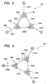
- Fig. 3 is a supplementary wiring diagram of a first group of first and second sets of three-phase windings included in the stator coil;
- Fig. 4 is a supplementary wiring diagram of a second group of first and second sets of three-phase windings included in the stator coil;
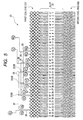
- Fig. 5 is a winding diagram development of part of the stator coil according to the embodiment of the invention;
- Fig. 6 is a winding diagram development of part of the stator coil according to the embodiment of the invention;
- Fig. 7 is a winding diagram development of part of the stator coil according to the embodiment of the invention;
- Fig. 8 is a view schematically illustrates wiring configuration of the three-phase windings of the first and second sets of the first and second groups according to the embodiment;
- Fig. 9 is a perspective view of conductor segments forming a stator coil according to a modification of the embodiment;
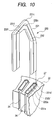
- Fig. 10 is a perspective view of the conductor segments shown in Fig. 9 being inserted in corresponding slots of a stator core of a stator according to the modification;
- Fig. 11 is a partially cross sectional enlarged view schematically illustrating part of the stator according to the modifitacation;
- Fig. 12 is a perspective view schematically illustrating a second coil end portion of the stator coil according to the modification;
- Fig. 13 is a perspective view schematically illustrating a first coil end portion of the stator coil according to the modification; and
- Fig. 14 is an enlarged winding diagram development of part of the stator coil according to the modification of the embodiment, which corresponds to part of the winding diagram development of Fig. 6.
- An embodiment of the present invention will be described hereinafter with reference to the accompanying drawings.
- Referring to the drawings, in which like reference characters refer to like parts in several views, particularly to Fig. 1, there is illustrated an
alternator 1 for vehicles, as an example of rotary electric machines. - The
alternator 1 installed in, for example, a vehicle includes astator 2, arotor 3, aframe 4, arectifier assembly 5, a voltage regulator and so on. - The
stator 2 is composed of astator core 22. Thestator core 22 has, for example, a substantially annular shape and first and second annular axial end surfaces. Thestator core 22 also has a plurality of (e.g. 96) slots 24 (see Figs. 5 to 7 and 10 to 13). For example, slot numbers of #1 to #96 are sequentially allocated in the 96 slots (see Figs. 5 to 7). Theslots 24 are formed through thestator core 22 and are circumferentially arranged at given intervals. The circumferential interval of adjacent slots defines a slot pitch corresponding to an electric angle of, for example, π/6 radian. - The
stator core 22 is fixed to an inner peripheral wall of theframe 4. Thestator 2 is also composed of astator coil 23. Thestator coil 23 is wound in theslots 24 of thestator core 22. Thestator core 22 further hasinsulators 27 inserted between conductor portions of thestator coil 23 disposed in theslots 24 and inner peripheral surfaces of theslots 24 to insulate therebetween. - The
stator coil 23 is composed of first andsecond groups second group 23B of first and second sets of three-phase windings is shifted by an electric angle of π/6 radian (30 degrees) in phase from thefirst group 23A of first and second sets of three-phase windings. - The
stator coil 23 has first and second coil end portions CE1 and CE2 axially opposed to each other and projecting from the first and second axial end surfaces of thestator core 22. For example, ends of windings of each phase included in the first andsecond groups stator coil 23. In the embodiment, ends of windings of each phase included in the first andsecond groups stator coil 23. Further details on each of the first andsecond groups - The
rotor 3 is attached to arotary shaft 6 rotatably supported in theframe 4 by bearings so that it is disposed within thestator core 22. One end of therotary shaft 6 is linked to apulley 20 such that therotary shaft 6 is rotatably driven by an engine (not shown) mounted in the vehicle through thepulley 20. - Specifically, the
rotor 3 is composed of a Lundell type (claw pole)core 7. TheLundell type core 7 has a pair of opposing circuit plates axially assembled to therotary shaft 6 and a plurality of claw portions extending from the outer peripheral side of the circular plates. The claw portions of one of the circuit plates and those of the other thereof are alternatively arranged in the circumferential direction of therotor 3. - The
rotor 3 is also composed offield windings 8 provided between the circular plates of thepole core 7,slip rings field windings 8 and a power supply. Therotor 3 is also composed of a diagonalflow cooling fan 11 and acentrifugal cooling fan 12 that allow cooling air to be delivered into theframe 4 by the rotation of thefans rotor 3. For example, the number of the claw portions is twelve, which corresponds to the number of poles of therotor 3, and six slots of thestator core 22 correspond to each pole. - The
frame 4 is configured to accommodate thestator 2 and therotor 3 such that thestator core 22 is fixedly disposed around the outer periphery of thepole core 7 such that the inner periphery of thestator core 22 is opposite to the outer periphery of thepole core 7 with a predetermined air gap. Specifically, theframe 4 is composed of afront frame 4A and arear frame 4B, which are fastened to each other by a plurality offastening bolts 43. This fastening structure fixedly supports thestator 2 in theframe 4. - The
rectifier assembly 5 includes first andsecond rectifiers second rectifiers second groups rectifier assembly 5 is configured to convert a three-phase AC (Alternating Current) voltage applied from thestator coil 23 into a DC voltage using both positive and negative half cycles of the three-phase AC voltage. - In the
alternator 1 described above, a field current is applied to the field winding 8 through theslip rings field windings 8 of therotor 3 is rotating based on torque applied from the engine through thepulley 20. In this situation, the field current flowing through thefield windings 8 magnetize the claw portions of one of the circuit plates to the north (N) pole, and those of the other thereof to the south. (S) pole. The rotation of the alternately magnetized north and south poles create magnetic fluxes, and the created magnetic fluxes induce a three-phase AC voltage in thestator coil 23. The induced three-phase AC voltage is rectified by therectifier 5, thereby generating a DC voltage. The voltage regulator is configured to control the field current flowing through thefield windings 8 in response to the alternator output voltage. - Next, the
stator 2 will be described in detail hereinafter. - As illustrated in Figs. 2 to 4, the
stator coil 23 of thestator 2 is composed of the first andsecond groups first group 23A consists of first andsecond sets - The
first set 330A includes a U-phase winding 330U1, a V-phase winding 330V 1, and a W-phase winding 330W1 whose output ends are connected to each other in delta-configuration. Thesecond set 340A includes an X-phase winding 340X1, a Y-phase winding 340Y1, and a Z-phase winding 340Z1 each having output and input ends. The input ends X1, Y1, and Z1 of the X-, Y-, and Z-phase windings 340X1, 340Y1, and 340Z1 of thesecond set 340A are respectively connected in series to the junctions (output ends) of the delta-connected U-, V-, and W-phase windings 330U1, 330V1, and 330W1 of thefirst set 330A. The output ends X1', Y1', and Z1' of the three-phase windings 340X1, 340Y1, and 340Z1 of thesecond set 340A serve respectively as output leads of thefirst group 23A. - The U-, V-, and W-phase winding 330U1, 330V1, and 330W1 are arranged to be shifted from each other by four slot pitches corresponding to an electric angle of 2 π/3 radian, and connected to each other to form the delta-connected three-phase winding 330A.
- Each of the
slots # 1 to #96 includes a first layer to a fourth layer located from the inside to the outside of thestator core 22. In Figs. 5 to 7, the first, second, third, and fourth layers are respectively illustrated schematically by chain, dashed, solid, and chain double-dashed lines. - Specifically, as illustrated in Figs. 5 to 7, the U-phase winding 330U1 is disposed in
slots # 55, #61, #67, ... every six slot pitches corresponding to one pole pitch. For example, part of the U-phase winding 330U1 being disposed in theslots # 55 and #61 consists of: - a first portion inserted in the
slot # 55 at the fourth layer thereof, - a second portion inserted in the
slot # 61 at the third layer thereof, - a first turn portion continuously connecting between one end of the first portion projecting from the
slot # 55 at the second coil end portion side of thecore 22 and that of the second portion projecting from theslot # 61 thereat, - a third portion inserted in the
slot # 55 at the second layer thereof, - a second turn portion continuously connecting between the other end of the second portion projecting from the
slot # 61 at the first coil end side of thecore 22 and one end of the third portion projecting from theslot # 55 thereat, - a fourth portion inserted in the
slot # 61 at the first layer thereof, and - a third turn portion continuously connecting between the other end of the third portion projecting from the
slot # 55 at the second coil end portion side of thecore 22 and one end of the fourth portion projecting from theslot # 61 thereat. - Similarly, the V-phase winding 330V1 is inserted in
slots # 51, #57, #63, ... every six slot pitches corresponding to one pole pitch; theseslots # 51, #57, #63, ... are respectively shifted from slots #55, #61, #67, .., by four slot pitches. The W-phase winding 330W1 is wound inslots # 47, #53, #59, ... every six slot pitches corresponding to one pole pitch; theseslots # 47, #53, #59 are respectively shifted from slots #51, #57, #63, ... by four slot pitches. - The X-, Y-, and Z-phase windings 340X1, 340Y1, and 340Z1 are arranged to be shifted from each other by four slot pitches corresponding to the electric angle of 2 π /3 radian.
- Specifically, as illustrated in Figs. 5 to 7, the X-phase winding 340X1 is disposed in
slots # 62, #68, #74, ... every six slot pitches corresponding to one pole pitch. Similarly, the Y-phase winding 340Y 1 is inserted inslots # 58, #64, #70, ... every six slot pitches corresponding to one pole pitch; theseslots # 58, #64, #70, ... are respectively shifted from slots #62, #68, #74, ...by four slot pitches. The Z-phase winding 340Z1 is wound inslots # 54, #60, #66, ... every six slot pitches corresponding to one pole pitch; theseslots # 54, #60, #66, ... are respectively shifted from slots #58, #64, #70,... by four slot pitches. - The
first set 330A of the three-phase windings 330U1, 330V1, and 330W and thesecond set 340A of the three-phase windings 340X1, 340Y1, and 340Z1 are arranged to be shifted from each other by one slot pitch (the electric angle π/6). - The connection of the junctions of the delta-connected U-, V-, and W-phase windings 33OU1, 330V1, and 330W1 to the input ends X1, Y1, and Z1 of the X-, Y-, and Z-phase windings 340X1, 340Y1, and 340Z1 is preferably welded to form three
weld portions first set 330A of three-phase windings and thesecond set 340A of three-phase windings. The output ends X1', Y1', and Z1' of the X-, Y-, and Z-phase windings 340X1) 340Y1, and 340Z1 are coupled to the first rectifier SA. - The
second group 23B consists of first andsecond sets - The
first set 330B includes an X-phase winding 330X2, a Y-phase winding 330Y2, and a Z-phase winding 330Z2, whose output ends are connected to each other in delta-configuration. Thesecond set 340B includes a U-phase winding 340U2, a V-phase winding 340V2, and a W-phase winding 340W2 each having output and input ends. The input ends U2, V2, and W2 of the U-, V-, and W-phase windings 340U2, 340V2, and 340W2 of thesecond set 340B are respectively connected in series to the junctions (output ends) of the delta-connected X-, Y-, and Z-phase windings 330X2, 330Y2, and 330Z2 of thefirst set 330B. The output ends U2', V2', and W2' of the three-phase windings 340U2, 340V2, and 340W2 of thesecond set 340B serve respectively as output leads of the second group 238. - The X-, Y-, and Z-phase winding 330X2, 330Y2, and 330X2 are arranged to be shifted from each other by four slot pitches corresponding to the electric angle of 2 π/3 radian, and connected to each other to form the delta-connected three-phase winding 330B.
- Specifically, as illustrated in Figs. 5 to 7, the X-phase winding 330X2 is disposed in
slots # 32, #38, #44, ... every six slot pitches corresponding to one pole pitch. For example, part of the X-phase winding 330X2 being disposed in theslots # 32 and #38 consists of: - a first portion inserted in the
slot # 32 at the fourth layer thereof, - a second portion inserted in the
slot # 38 at the third layer thereof, - a first turn portion continuously connecting between one end of the first portion projecting from the
slot # 32 at the second coil end portion side of thecore 22 and that of the second portion projecting from theslot # 38 thereat, - a third portion inserted in the
slot # 32 at the second layer thereof, - a second turn portion continuously connecting between the other end of the second portion projecting from the
slot # 38 at the first coil end side of thecore 22 and one end of the third portion projecting from theslot # 32 thereat, - a fourth portion inserted in the
slot # 38 at the first layer thereof, and - a third turn portion continuously connecting between the other end of the third portion projecting from the
slot # 32 at the second coil end portion side of thecore 22 and one end of the fourth portion projecting from theslot # 38 thereat. - Similarly, the Y-phase winding 330Y2 is inserted in
slots # 28, #34, #40, ... every six slot pitches corresponding to one pole pitch; theseslots # 28, #34, #40, ... are respectively shifted from slots #32, #38, #44, ... by four slot pitches. The Z-phase winding 330Z2 is wound inslots # 24, #30, #36, ... every six slot pitches corresponding to one pole pitch; theseslots # 24, #30, #36, ... are respectively shifted from slots #28, #34, #40, ... by four slot pitches. - The U-, V-, and W-phase windings 340U2, 340V2, and 340W2 are arranged to be shifted from each other by four slot pitches corresponding to the electric angle of 2 π/ 3 radian.
- Specifically, as illustrated in Figs. 5 to 7, the U-phase winding 340U2 is disposed in
slots # 37, #43, #49, ... every six slot pitches corresponding to one pole pitch. Similarly, the V-phase winding 340V2 is inserted inslots # 33, #39, #45, ... every six slot pitches corresponding to one pole pitch; theseslots # 33, #39, #45 are respectively shifted from slots #37, #43, #49, ...by four slot pitches. The W-phase winding 340W2 is wound inslots # 29, #35, #41, ... every six slot pitches corresponding to one pole pitch; theseslots # 29, #35, #41 are respectively shifted from slots #33, #39, #45, ... by four slot pitches. - The
first set 330B of the three-phase windings 330X2, 330Y2, and 330Z2 and thesecond set 340B of the three-phase windings 340U2, 340V2, and 340W2 are arranged to be shifted from each other by one slot pitch corresponding to the electric angle of π/6. - The connection of the junctions of the delta-connected X-, Y-, and Z-phase windings 330X2, 330Y2, and 330Z2 to the input ends U2, V2, and W2 of the U-, V-, and W-phase windings 340U2, 340V2, and 340W2 is preferably welded to form three
weld portions first set 330B of three-phase windings and thesecond set 340B of three-phase windings. The output ends U2', V2', and W2' of the U-, V-, and W-phase windings 340U2, 340V2, and 340W2 are coupled to thesecond rectifier 5B. - Specifically, the second turn portions of the windings of each of the first and
second groups stator core 22 constitute the first coilend portion CE 1 of thestator coil 23. The first turn portions of the windings of each of the first andsecond groups stator core 22 constitute the second coil end portion CE2 of thestator coil 23. - Fig. 8 schematically illustrates wiring configuration of the three-phase windings of the first and second sets of the first and
second groups stator core 22. Specifically, connection leads 25 extend from the draw-out positions of the U-phase winding 330U1 so that they correspond to the ends of theU-phase winding 330U 1. - Similarly, circled reference characters V1 and V1' represent draw-out positions of the ends of the V-phase winding 330V1 from the first coil end portion side of the
stator core 22, and connection leads 25 extend from the draw-out positions of the V-phase winding 330V1 so that they correspond to the ends of the V-phase winding 330V1. Circled reference characters W1 and W1' represent draw-out positions of the ends of the W-phase winding 330W 1 from the first coil end portion side of thestator core 22, and connection leads 25 extend from the draw-out positions of the W-phase winding 330W1 so that they correspond to the ends of the W-phase winding 330W1. - Circled reference characters X1 and X1' represent draw-out positions of the ends of the X-phase winding 340X1 from the first coil end portion side of the
stator core 22. Connection and output leads 25 and 26 extend from the draw-out positions of the X-phase winding 340X1 so that they correspond to the ends of the X-phase winding 340X1. Similarly, circled reference characters Y and Y1' represent draw-out positions of the ends of the Y-phase winding 340Y1 from the first coil end portion side of thestator core 22. Connection and output leads 25 and 26 extend from the draw-out positions of the Y-phase winding 340Y1 so that they correspond to the ends of the Y-phase winding 34OY1. Circledreference characters 21 and Z1' represent draw-out positions of the ends of the Z-phase winding 340Z1 from the first coil end portion side of thestator core 22. Connection and output leads 25 and 26 extend from the draw-out positions of the Z-phase winding 340Z1 so that they correspond to the ends of the Z-phase winding 340Z1. - Like the
first group 23A, circled reference characters U2 and U2' represent draw-out positions of the ends of the U-phase winding 340U2 from the first coil end portion side of thestator core 22. Connection and output leads 25 and 26 extend from the draw-out positions of the U-phase winding 340U2 so that they correspond to the ends of the U-phase winding 340U2. Similarly, circled reference characters V2 and V2' represent draw-out positions of the ends of the V-phase winding 340V2 from the first coil end portion side of thestator core 22. Connection and output leads 25 and 26 extend from the draw-out positions of the V-phase winding 340V2 so that they correspond to the ends of the V-phase winding 340V2. Circled reference characters W2 and W2' represent draw-out positions of the ends of the W-phase winding 340W2 from the first coil end portion side of thestator core 22. Connection and output leads 25 and 26 extend from the draw-out positions of the W-phase winding 340W2 so that they correspond to the ends of the W-phase winding 340W2. - Circled reference characters X2 and X2' represent draw-out positions of the ends of the X-phase winding 340X2 from the first coil end portion side of the
stator core 22, and connection leads 25 extend from the draw-out positions of the X-phase winding 340X2 so that they correspond to the ends of the X-phase winding 340X2. Similarly, circled reference characters Y2 and Y2' represent draw-out positions of the ends of the Y-phase winding 340Y2 from the first coil end portion side of thestator core 22, and connection leads 25 extend from the draw-out positions of the Y-phase winding 340Y2 so that they correspond to the ends of the Y-phase winding 340Y2. Circled reference characters Z2 and Z2' represent draw-out positions of the ends of the Z-phase winding 340Z2 from the first coil end portion side of thestator core 22, and connection leads 25 extend from the draw-out positions of the Z-phase winding 340Z2 so that they correspond to the ends of the Z-phase winding 340Z2. - Note that the specification will describe the draw-out positions from the first coil end portion side of the
stator coil 23, which are represented by X1 and X1' and the like, as the positions of both ends of corresponding windings. In addition, circled reference numerals illustrated in Fig. 8 represent circumferential positions of both ends of each winding included in the first andsecond groups slots 24 illustrated in Figs. 5 to 7. - For example, Figs. 6 and 8 clearly show that the ends X1 and X1' of the X-phase winding 340X1 are drawn out from the first coil end portion side of the
stator core 22 at the circumferential position identical with that of theslot # 59. Note that the first portion of the X-phase winding 340X1 from which the end X1 extends is actually inserted in theslot # 56 shifted counterclockwise from theslot # 59 by three slots. In addition, the second portion of the X-phase winding 340X1 from which the end X1.' extends is actually inserted in theslot # 62 shifted clockwise from theslot # 59 by three slots. This can be established in the ends of each of the remaining windings. - In the embodiment, as illustrated in Fig. 8, the first grouped ends U1, U1', V1, V1', W1, W1', X1, X1', Y1, Y1', Z1, and 21' of the windings of the first and
second sets first group 23A and the second grouped ends U2, U2', V2, V2', W2, W2', X2, X2', Y2, Y2', Z2, and Z2' of the windings of the first andsecond sets second group 23B are so arranged that the first grouped ends are separated from the second grouped ends in a circumferential direction of thestator core 22. - In other words, the first grouped ends of the windings of the first and
second sets first group 23A and the second grouped ends of the windings of the first andsecond sets second group 23B are disposed not to be overlapped onto the second grouped ends. - Moreover, when focusing on the
first group 23A, the circumferential positions of the ends U1, U1', V1, V1', W1., and W1' included in thefirst set 330A are arranged in a circumferential direction of thestator core 22 between the ends X1, X1', Y1, and Y1' of the windings included in thesecond set 340A and the ends Z1 and Z1' of the windings included therein (see Figs. 6 and 8). - In addition, the tip ends X1, U1', and V1 of the windings 340X1, 330U1, and 330V1 are respectively drawn out by the corresponding connection leads 25 to be bundled together in a group so that the bundled tip ends X1, U1', and V1 of the windings 340X1, 330U1, and 330V1 are welded to form the
weld portion 332A. Similarly, the tip ends Y1, V1', and W1 of the windings 340Y1, 330V1, and 33OW1 are respectively drawn out by the corresponding connection leads 25 to be bundled together in a group so that the bundled tip ends Y1, V1', and W1 of the windings 340Y1, 330V1, and 330W1 are welded to form theweld portion 334A. Moreover, the tip ends U1, W1', and Z1 of the windings 330U1, 330W1, and 340Z1 are respectively drawn out by the corresponding connection leads 25 to be bundled together in a group so that the bundled tip ends U1, W1', and Z1 of the windings 33OU1, 330W1, and 340Z1 are welded to form theweld portion 336A. - The
weld portions stator core 22 to be separated from the remaining tip ends (X1', Y1', Z1') and the corresponding leads 25 drawn out from the tip ends (X1', Y1', Z1'). In addition, theweld portions slots 24 of the core 22). - Moreover, as illustrated in Fig. 8, the tip ends of the windings, which form each of the
weld portions stator core 22 over the radially inner edge side of theslots 24. Furthermore, the tip end of the winding disposed at the middle of the ends of the windings forming each of the weld portions extends in the axial direction of thecore 22. - For example, when focusing on the
weld portion 332A, as illustrated in Fig. 8, the tip ends X1, U1', and V1 of the windings 340X1, 330U1, and 330V1, which form theweld portion 332A, are aligned in a circumferential direction of thestator core 22, and are arranged over the radially inner edge side of theslots 24. Furthermore, the end U1' (connection lead 25) of the winding 330U1 disposed at the middle of the tip ends X1, U1', and V1 of theweld portion 332A extends in the axial direction of thecore 22 without extending any circumferential directions. The arrangement features of theweld portion 332A can be established in the remainingweld portions - In addition, the
weld portions core 22. Moreover, one end (connection lead) of the winding drawn out from one of theslots 24 for one of theweld portions slots 24 for another one of theweld portions slots 24 jumps over the one end of the winding drawn out from another one of theslots 24; this one of theweld portions weld portions - For example, assuming that, in Fig. 8, the predetermined circumferential direction is the counterclockwise direction, the end Y1 (lead 25) of the winding 340Y1 drawn out from the corresponding one of the
slots 24 for theweld portion 334A disposed forwardly in the counterclockwise direction from theweld portion 332A is disposed to intersect with the end V1 (lead 25) of the winding 330V1 drawn out from another one of theslots 24 for theweld portion 332A such that theend Y 1 of the winding340Y 1 jumps over the end V1 of the winding330V 1. - Similarly, when focusing on the
second group 23B, the circumferential positions of the ends X2, X2', Y2, Y2', Z2, and Z2' included in thefirst set 330B are arranged circumferentially between the ends W2, W2', V2, and V2' of the windings included in thesecond set 340B and the ends U2 and U2' of the windings included therein (see Figs. 5 and 7). - In addition, the tip ends W2, Z2', and Y2 of the windings 340W2, 330Z2, and 330Y2 are respectively drawn out by the corresponding connection leads 25 to be bundled together in a group so that the bundled tip ends W2, Z2', and Y2 of the windings 340W2, 330Z2, and 330Y2 are welded to form the
weld portion 332B. Similarly, the tip ends V2, Y2', and X2 of the windings 340V2, 330Y2, and 33OX2 are respectively drawn out by the corresponding connection leads 25 to be bundled together in a group so that the bundled ends V2, Y2', and X2 of the windings 340V2, 330Y2, and 330X2 are welded to form theweld portion 334B. Moreover, the tip ends Z2, X2', and U2 of the windings 330Z2, 330X2, and 340U2 are respectively drawn out by the corresponding connection leads 25 to be bundled together in a group so that the bundled tip ends Z2, X2', and U2 of the windings 330Z2, 330X2, and 340U2 are welded to form theweld portion 336B. - The
weld portions weld portions slots 24 of the core 22). - Moreover, as illustrated in Fig. 8, the tip ends of the windings, which form each of the
weld portions slots 24. Furthermore, the tip end of the winding disposed at the middle of the tip ends of the windings forming each of the weld portions in the axial direction of thecore 22. - For example, when focusing on the
weld portion 332B, as illustrated in Fig. 8, the tip ends W2, Z2', and Y2 of the windings 340W2, 330Z2, and 330Y2, which form theweld portion 332B, are circumferentially aligned, and are arranged over the radially inner edge side of theslots 24. Furthermore, the end Z2' (connection lead 25) of the winding 330Z2 disposed at the middle of the ends W2, Z2', and Y2 of theweld portion 332B extends in the axial direction of thecore 22 without extending any circumferential directions. The arrangement features of theweld portion 332B can be established in the remainingweld portions - In addition, the
weld portions core 22. Moreover, one end (connection lead) of the winding drawn out from one of theslots 24 for one of theweld portions slots 24 for another one of theweld portions slots 24 jumps over the one end of the winding drawn out from another one of theslots 24; this one of theweld portions weld portions - For example, assuming that, in Fig. 8, the predetermined circumferential direction is the clockwise direction, the end V2 (connection lead 25) of the winding 340V2 drawn out from the corresponding one of the
slots 24 for theweld portion 334B disposed forwardly in the clockwise direction from theweld portion 332B is arranged to intersect with the end Y2 (connection lead 25) of the winding 330Y2 drawn out from the corresponding slot for theweld portion 332B such that the end V2 of the winding 340V2 jumps over the end Y2 of the winding 330Y2. - As described above, the
stator coil 23 of thealternator 1 according to the embodiment includes the first andsecond groups - Particularly, in the
stator coil 23 of thealternator 1 according to the embodiment, the first grouped ends of the three-phase windings of the first andsecond sets first group 23A and the second grouped ends of the three-phase windings of the first andsecond sets second group 23B are so arranged that the first grouped ends are circumferentially separated from the second grouped ends. - This configuration allows the lengths of the connection leads 25 included in each of the first and
second groups second groups - In addition, as illustrated in Figs. 5, 6, and 8, the circumferential positions of the ends of the delta-connected three-phase windings of the first set (330A, 330B) are arranged to be circumferentially included in the circumferential positions of the ends of the remaining windings of the second set (340A, 3408). This allows the connection leads 25 connecting between the output ends of the delta-connected three-phase windings of the first set (330A, 330B) and the three-phase windings of the second set (340A, 340B) to locally concentrate in the circumferential direction of the
core 22. This makes it possible to further simplify connections between the output ends of the delta-connected three-phase windings of the first set (330A, 330B) and the three-phase windings of the second set (340A, 340B). With simplicity of connections between the output ends of the delta-connected three-phase windings of the first set (330A, 330B) and the three-phase windings of the second set (340A, 340B), phase-to-phase insulation of the three-phase windings included in each of the first andsecond groups stator core 23 andstator 2 to be easily manufactured and downsized. - The output leads 26 of each of the first and
second groups core 22. Accordingly, even if arrangements of the output leads 26 from the first andsecond groups rectifier assembly 5 that is determined not to interfere the brushes and/or the voltage regulator, it is possible to easily adjust the arrangements of the output leads 26 to the limited space. This can prevent complicated wiring configuration. - Moreover, the weld portions between the ends of the three-phase windings of the first set (330A, 340A) and those of the three-phase windings of the second set (330B, 340B) of each of the first and
second groups leads 25 drawn out from the output ends of the three-phase windings of the second set (340A, 340B) of each of the first andsecond groups leads 25 drawn out from the output ends of the three-phase windings to be reduced, making it easy to manufacture thestator coil 23 andstator 2. - In the embodiment, the weld portions between the ends of the three-phase windings of the first set (330A, 340A) and those of the three-phase windings of the second set (330B, 340B) of each of the first and
second groups core 22. This allows sufficient spaces between therear frame 4B accommodating therein thestator 2 and each weld portion to be easily secured. Thus, it is unnecessary to increase the size of therear frame 4B in order to avoid interference between each weld portion and the inner peripheral surface of therear frame 4B. This makes it possible to further downsize thestator coil 23 andstator 2. - Moreover, the ends of the windings, which form each of the
weld portions slots 24. This makes it possible to easily bundle the ends of the windings for each of the weld portions and weld them. - Furthermore, the end of the winding disposed at the middle of the ends of the windings forming each of the weld portions extends in the axial direction of the
core 22. That is, the end of the winding disposed at the middle of the ends of the windings forming each of the weld portions extends in the axial direction of thecore 22 without extending any circumferential directions. This allows oscillations occurring during rotatably drive of the alternator 1 (rotor 2) to decrease. - In each of the first and
second groups second groups second groups second groups slots 24 and easily bundle them. - In the embodiment, as a modification of the embodiment, each of the three-phase windings included in the first and
second groups - In each of the first and
second groups slot 24. Four conductor members being disposed in one of theslots 24 are aligned in the radial direction and respectively disposed in an innermost layer, an inner middle layer, an outer middle layer, and an outermost layer from the inner periphery of each slot 24 (see Figs. 10 and 11). - A
conductor member 231a disposed in the innermost layer of one of theslots 24 is paired with aconductor member 231b disposed in the outermost layer of anotherslot 24 that is spaced apart from the one of theslots 24 by one pole pitch (six slot pitches) in clockwise direction. Similarly, aconductor member 232a disposed in the inner middle layer of one of theslots 24 is paired with aconductor member 232b disposed in the outer middle layer of anotherslot 24 that is spaced apart from the one of theslots 24 by one pole pitch in clockwise direction. The pairedconductor members turn portion 231 c at the first axial end surface side of thecore 22. The pairedconductor members turn portion 232c at the first axial end surface side of thecore 22. , - Accordingly, as illustrated in Figs. 9 and 10, at the first axial end surface side of the
stator core 22, a continuous conductor portion consisting of theconductor member 232a disposed in the inner middle layer, theconductor member 232b disposed in the outer middle layer, and theturn portion 232c connecting therebetween is enclosed by a continuous conductor portion consisting of theconductor member 231a disposed in the innermost layer, theconductor member 231b disposed in the outermost layer, and theturn portion 231c connecting therebetween. - Specifzcally, at the fist axial end surface side of the
stator core 22, theturn portion 232c as a connection portion between the paired conductor members is surrounded by theturn portion 231c as a connection portion between the paired conductor members. Connection between theconductor member 232b inserted in the outer middle layer and theconductor member 232a inserted in the inner middle layer provides a middle layer coil end. Connection between theconductor member 231b inserted in the outermost layer and theconductor member 231a inserted in the innermost layer provides an outer layer coil end disposed at the outer side of the middle layer coil end. - The
conductor member 232a arranged in the inner middle layer of one of theslots 24 is also paired with aconductor member 231a' arranged in the innermost layer of anotherslot 24 that is one pole pitch clockwise spaced apart from the one of theslots 24. Similarly, theconductor member 231b' arranged in the outermost layer of one of theslots 24 is also paired with aconductor member 232b arranged in the outer middle layer of anotherslot 24 that is one pole pitch clockwise spaced apart from the one of theslots 24. Junctions between the paired conductor members are disposed at the second axial end surface side of thestator core 22. - As illustrated in Figs. 9 to 11, each reference number with no dash and that with a dash (') are assigned to the identical portions of
different conductor members 231. Similarly, each reference number with no dash and that with a dash (') are assigned to the identical portions ofdifferent conductor members 232. - Thus, at the second axial end surface side of the core 22, as illustrated in Fig. 9, an
outside connection portion 233b connecting theconductor member 231 b' disposed in the outermost layer and theconductor member 232b disposed in the outer middle layer and an innerside connection portion 233a connecting theconductor member 231a' disposed in the innermost layer and theconductor member 232a disposed in the inner middle layer are arranged to be shifted from each other in the radial and circumferential directions. Connection of theoutermost conductor member 231b' and the outermiddle conductor member 232b, and that of theinnermost conductor member 231a' and the innermiddle conductor member 232a provide two adjacent coil-end layers. The two adjacent coil-end layers are arranged on different concentric circles, respectively. - As illustrated in Fig. 9, the
conductor member 231a inserted in the innermost layer, theconductor member 231b inserted in the outermost layer, and theturn portion 231c provide a U or V shapedlarge conductor segment 231. Similarly, theconductor member 232a inserted in the inner middle layer, theconductor member 232b inserted in the outer middle layer, and theturn portion 232c provide a U or V shapedsmall conductor segment 232. A basicconductor segment unit 230 consists of a pair of thelarge conductor segment 231 and thesmall conductor segment 232. - The
large conductor segment 231 is composed of a pair of straight conductor portions corresponding to theconductor members turn portion 231c. The pairedstraight conductor portions turn portion 231c are to be inserted into theslots 24. - The
larger conductor segment 231 is also composed of projecting end portions (legs) 231g continuing from the other ends of thestraight conductor portions slots 24 when thestraight conductor portions slots 24. The projectingend portions 231g are bent with a predetermined electric angle with respect to the axial direction of the correspondingslots 24. - The
turn portion 231c of thelarge conductor segment 231 is composed of a tip portion and a pair ofslant portions 231f. The pairedslant portions 231f are designed to continue from both ends of the tip portion, slant with a predetermined electric angle with respect to the axial direction of the correspondingslots 24, and lead to thestraight conductor portions - Similarly, the
small conductor segment 232 is composed of a pair of straight conductor portions corresponding to theconductor members turn portion 232c. The pairedstraight conductor portions turn portion 232c are to be inserted into theslots 24. - The
small conductor segment 232 is also composed of projecting end portions (legs) 232g continuing from the other ends of thestraight conductor portions slots 24 when thestraight conductor portions slots 24. The projectingend portions 232g are bent with a predetermined electric angle with respect to the axial direction of the correspondingslots 24. - The
turn portion 232c of thesmall conductor segment 232 is composed of a tip portion and a pair ofslant portions 232f. The pairedslant portions 232f are designed to continue from both ends of the tip portion, slant with a predetermined electric angle with respect to the axial direction of the correspondingslots 24, and lead to thestraight conductor portions turn portions slots 24 through the first axial end surface side of the core 22 provide the first coil end portion CE1 (see Fig. 13). - The above-described configuration is applied to the
conductor segment units 230 disposed in all theslots 24. Atip end 231e' of theslant portion 231g' extending from thestraight conductor portion 231b' inserted in the outermost layer and atip end 232e of theslant portion 232g extending from thestraight conductor portion 232b inserted in the outer middle layer are welded together to form an outsidejoint portion 233b. Similarly, atip end 232d of theslant portion 232g extending from thestraight conductor portion 232a inserted in the inner middle layer and atip end 231d' of theslant portion 231g' extending from thestraight conductor portion 231a' inserted in the innermost layer are welded together to form an insidejoint portion 233a. The inside and outsidejoint portions slots 24 through the second axial end surface side of the core 22 provide the second coil end portion CE2 (see Fig. 12). - In the modification of the embodiment, the above described
conductor segment units 230 provide thestator core 23 with the same winding structure as illustrated in Figs. 5 to 7. - Specifically, when focusing on the
first group 23A of three-phase windings, six-phase windings that are shifted from one another by an electric angle of π/6 radian in phase are disposed in every six of theslots 24 of thestator core 22 corresponding to one pole-pitch. For example, part of the U-phase winding 330U1. that is composed of theconductor segment units 230 being disposed in theslots # 55 and #61 is illustrated in Fig. 14 corresponding to part of Fig. 6. In Fig. 14, circlednumerals slots # 55 and #61. - As clearly illustrated in Fig. 14, part of the U-phase winding
33OU 1 being disposed in theslots # 55 and #61 consists of: - the
straight conductor portion 231b' corresponding to the first portion and inserted in theslot # 55 at the fourth layer thereof, - the
straight conductor portion 232b corresponding to the second portion and inserted in theslot # 61 at the third layer thereof, - a set of the
slant portions 231g', 232g, and the insidejoint portion 233b (tip ends 231e', 232e), which corresponds to the first turn portion and continuously connecting between one end of thestraight conductor portion 231b' projecting from theslot # 55 at the second coil end portion side of thecore 22 and that of thestraight conductor portion 232b projecting from theslot # 61 thereat, - the
straight conductor portion 232a corresponding to the third portion and inserted in theslot # 55 at the second layer thereof, - the
turn portion 232c corresponding to the second turn portion and continuously connecting between the other end of thestraight conductor portion 232b projecting from theslot # 61 at the first coil end side of thecore 22 and one end of thestraight conductor portion 232a third portion projecting from theslot # 55 thereat, - the
straight conductor portion 231a' corresponding to the fourth portion and inserted in theslot # 61 at the first layer thereof, and - a set of the
slant portions joint portion 233a (tip ends 232d, 231d'), which corresponds to the third turn portion continuously connecting between the other end of thestraight conductor portion 232a projecting from theslot # 55 at the second coil end portion side of thecore 22 and one end of thestraight conductor portion 231a' projecting from theslot # 61 thereat. - Specifically, in the modification, U-phase winding 330U1 disposed in one of the
slots 24, V-phase winding 330V and W-phase winding 330W 1 respectively disposed inother slots 24 that are spaced apart from the one of theslots 24 by 4 or 8 slot pitches are connected to form afirst set 330A of delta-connected three-phase windings. X-phase winding 340X1, Y-phase winding 340Y1, and Z-phase winding 340Z1, which are respectively inserted in slots respectively spaced apart from the slots for the U-, V-, and W-phase windings are disposed, are respectively connected in series to the three junctions of the delta-connected three-phase winding of thefirst set 330A to provide three-phase windings of asecond set 340A. - Similarly, when focusing on the
second group 23B of three-phase windings, six-phase windings that are shifted from one another by an electric angle of π/6 radian in phase are disposed in every six of theslots 24 of thestator core 22 corresponding to one pole-pitch. - X-phase winding 330X2 disposed in one of the
slots 24, Y-phase winding 330Y2 and Z-phase winding-330Z2 respectively disposed inother slots 24 that are spaced apart from the one of theslots 24 by 4 or 8 slot pitches are connected to form afirst set 330B of delta-connected three-phase windings. U-phase winding 340U2, V-phase winding 340V2, and W-phase winding 340W2, which are respectively inserted in slots respectively spaced apart from the slots for the U-, V-, and W-phase windings are disposed, are respectively connected in series to the three junctions of the delta-connected three-phase winding of thefirst set 330B to provide three-phase windings of asecond set 340B. - Because both ends (connection and output leads) of the three-phase windings included in each of the first and
second groups conductor segment units 230, theconductor segment units 230 include some special conductor segment units to provide the connection and output leads. Specifically, as can be seen from the enlarged winding diagram developments of Figs. 5 and 6, the tip portion of theturn portion 231c of some of theconductor segment units 230 is cut, and the cut ends of the tip portion are designed to axially extend as the output leads and parts of the connection leads, thereby forming some of the special conductor segment units. - As described above, in the modification, the first and
second groups conductor segment units 230. This allows the connection and output leads to be arranged at the first coil end CE1 formed by theturn portions 231c of thelarge conductor segments 231. Accordingly, in addition to the effects obtained by the embodiment, it is possible to weld the ends of the three phase windings and to route the connection and output leads at the turn portion side of thestator coil 23, thereby more easily manufacturing thestator coil 23 and thestator 2. - In the embodiment and its modification, the first set (330A, 330B) of three-phase windings of each of the first and
second groups second groups second groups second groups - Similarly, the
second group 23B of first and second sets of three-phase windings is disposed to be shifted in phase from thefirst group 23A of first and second sets of three-phase windings by an electric angle of π /6 radian. This arrangement permits magnetic noise to further decrease. In the present invention, thesecond group 23B of first and second sets of three-phase windings can be disposed to be shifted in phase from thefirst group 23A of first and second sets of three-phase windings by another electric angle. - In the embodiment and its modification, it is possible to freely set the number of turns of respective three-phase windings included in each of the first and
second groups - In the embodiment and its modification, the present invention is applied to an alternator for vehicles, but the present invention is not limited to the application. Specifically, the present invention can be applied to other types of rotary electric machines, such as motors for vehicles or the like.
- While there has been described what is at present considered to be the embodiment and its modification of the present invention, it will be understood that various modifications which are not described yet may be made therein, and it is intended to cover in the appended claims all such modifications as fall within the true spirit and scope of the invention.
Claims (18)
- A rotary electric machine comprising:a stator core having axially opposing end surfaces and a plurality of substantially circumferentially spaced slots; anda stator coil, the stator coil comprising:a first group of first and second sets of three-phase windings disposed in part of the slots, the first set including first three-phase windings each with output ends, the output ends of the first three-phase winding being connected in series to each other to form delta configuration with junctions between the first three-phase windings, the second set including second three-phase windings having output and input ends, the input ends being respectively connected in series to the junctions of the first three-phase windings, anda second group of third and fourth sets of three-phase windings disposed in another part of the slots, the third set including third three-phase windings each with output ends, the output ends of the third three-phase winding being connected in series to each other to form delta configuration with junctions between the third three-phase windings, the fourth set including fourth three-phase windings having output and input ends, the input ends being respectively connected in series to the junctions of the third three-phase windings, the output ends of the first to fourth three-phase windings and the input ends of the second and fourth windings being disposed at one of the opposing end surface sides of the stator core, the output ends of the first and second three-phase windings of the first and second sets included in the first group being separated from the output ends of the third and fourth three-phase windings of the third and fourth sets included in the second group.
- A rotary electric machine according to claim 1, wherein the first group includes first weld portions formed by welding respectively the junctions of the first three-phase windings and the input ends of the second three-phase windings together, and the second group includes second weld portions formed by welding respectively the junctions of the third three-phase windings and the input ends of the fourth three-phase windings together, the first weld portions being arranged to be separated from the output ends of the second three-phase windings, the second weld portions being arranged to be separated from the output ends of the fourth three-phase windings.
- A rotary electric machine according to claim 2, wherein the first and second weld portions are locally disposed in opposition to an inner peripheral side of one of the opposing end surfaces of the stator core.
- A rotary electric machine according to claim 2, wherein each of the first weld portions is composed of:one of the output ends of one of the first three-phase windings,one of the output ends of another one of the first three-phase windings, andthe input end of one of the second three-phase windings, the output and input ends constituting each of the first weld portions being aligned substantially circumferentially to be arranged in opposition to an inner peripheral side of one of the opposing end surfaces of the stator core, and wherein each of the second weld portions is composed of:one of the output ends of one of the third three-phase windings,one of the output ends of another one of the third three-phase windings, andthe input end of one of the fourth three-phase windings, the output and input ends constituting each of the second weld portions being aligned circumferentially to be arranged in opposition to the inner peripheral side of one of the opposing end surfaces of the stator core.
- A rotary electric machine according to claim 4, wherein any one of the circumferential aligned ends of each of the first weld portions is disposed at the middle thereof, and the middle-disposed end extends substantially in the axial direction of the stator core, and any one of the circumferential aligned ends of each of the third weld portions is disposed at the middle thereof, and the middle-disposed end extends substantially in the axial direction of the stator core.
- A rotary electric machine according to claim 2, wherein the first weld portions are substantially circumferentially aligned, each of the first weld portions is composed of:one of the output ends of one of the first three-phase windings,one of the output ends of another one of the first three-phase windings, andthe input end of one of the second three-phase windings, one of the ends constituting one of the first weld portions is drawn out from one of the slots and is arranged to intersect with one of the ends of one of the first three-phase windings disposed in another one of the slots constituting another one of the first weld portions such that the one end of the winding drawn out from the one of the slots jumps over that of the winding drawn out from another one of the slots, the one of the first weld portions being disposed forwardly in a predetermined circumferential direction from another one of the first weld portions, and wherein the second weld portions are substantially circumferentially aligned, each of the second weld portions is composed of:one of the output ends of one of the third three-phase windings,one of the output ends of another one of the third three-phase windings, andthe input end of one of the fourth three-phase windings, one of the ends constituting one of the third weld portions is drawn out from one of the slots and is arranged to intersect with one of the ends of one of the third three-phase windings disposed in another one of the slots constituting another one of the third weld portions such that the one end of the winding drawn out from the one of the slots jumps over that of the winding drawn out from another one of the slots, the one of the third weld portions being disposed forwardly in a predetermined circumferential direction from another one of the third weld portions.
- A rotary electric machine according to claim 1, wherein each of the first and second three-phase windings comprises a plurality of conductor segment units each having a substantially U shape turn portion and substantially straight portions extending therefrom and having tip end portions, one of the tip end portions of one of the conductor segment units being sequentially joined to one of the tip end portions of another one of the conductor segment units to form a series-connected winding in each phase corresponding to each of the first and second three-phase windings, and each of the third and fourth three-phase windings comprises a plurality of conductor segment units each having a substantially U shape turn portion and substantially straight portions extending therefrom and having tip end portions, one of the tip end portions of one of the conductor segment units being sequentially joined to one of the tip end portions of another one of the conductor segment units to form a series-connected winding in each phase corresponding to each of the third and fourth three-phase windings.
- A rotary electric machine according to claim 1, wherein the turn portions of the first, second, third, and fourth three-phase windings provide a coil end of the stator coil, the output ends of the first three-phase windings and the output and input ends of the second three-phase windings are arranged at the coil end of the stator coil, and the output ends of the third three-phase windings and the output and input ends of the fourth three-phase windings are arranged at the coil end of the stator coil.
- A rotary electric machine comprising:a stator core having axially opposing end surfaces and a plurality of substantially circumferentially spaced slots; anda stator coil, the stator coil comprising:wherein the circumferential positions of the output positions of at least one of the first three-phase windings and the third three-phase windings are disposed to be included in the circumferential positions of the output ends of at least one of the second three-phase windings and the fourth three-phase windings.a first group of first and second sets of three-phase windings disposed in part of the slots, the first set including first three-phase windings each with output ends disposed respectively at first circumferential positions in opposition to the stator core, the output ends of the first three-phase winding being connected in series to each other to form delta configuration with junctions between the first three-phase windings, the second set including second three-phase windings having output and input ends, the input ends being respectively connected in series to the junctions of the first three-phase windings, anda second group of third and fourth sets of three-phase windings disposed in another part of the slots, the third set including third three-phase windings each with output ends disposed respectively at first circumferential positions in opposition to the stator core, the output ends of the third three-phase winding being connected in series to each other to form delta configuration with junctions between the third three-phase windings, the fourth set including fourth three-phase windings having output and input ends, the input ends being respectively connected in series to the junctions of the third three-phase windings, the output ends of the first to fourth three-phase windings and the input ends of the second and fourth windings being disposed at one of the opposing end surface sides of the stator core,
- A rotary electric machine according to claim 9, wherein the first group includes first weld portions formed by welding respectively the junctions of the first three-phase windings and the input ends of the second three-phase windings together, and the second group includes second weld portions formed by welding respectively the junctions of the third three-phase windings and the input ends of the fourth three-phase windings together, the first weld portions being arranged to be separated from the output ends of the second three-phase windings, the second weld portions being arranged to be separated from the output ends of the fourth three-phase windings.
- A rotary electric machine according to claim 10, wherein the first and second weld portions are locally disposed in opposition to an inner peripheral side of one of the opposing end surfaces of the stator core.
- A rotary electric machine according to claim 10, wherein each of the first weld portions is composed ofone of the output ends of one of the first three-phase windings,one of the output ends of another one of the first three-phase windings, andthe input end of one of the second three-phase windings, the output and input ends constituting each of the first weld portions being aligned substantially circumferentially to be arranged in opposition to an inner peripheral side of one of the opposing end surfaces of the stator core, and wherein each of the second weld portions is composed of:one of the output ends of one of the third three-phase windings,one of the output ends of another one of the third three-phase windings, andthe input end of one of the fourth three-phase windings, the output and input ends constituting each of the second weld portions being aligned circumferentially to be arranged in opposition to the inner peripheral side of one of the opposing end surfaces of the stator core.
- A rotary electric machine/according to claim 12, wherein any one of the circumferential aligned ends of each of the first weld portions is disposed at the middle thereof, and the middle-disposed end extends substantially in the axial direction of the stator core, and any one of the circumferential aligned ends of each of the third weld portions is disposed at the middle thereof, and the middle-disposed end extends substantially in the axial direction of the stator core.
- A rotary electric machine according to claim 10, wherein the first weld portions are substantially circumferentially aligned, each of the first weld portions is composed of:one of the output ends of one of the first three-phase windings,one of the output ends of another one of the first three-phase windings, andthe input end of one of the second three-phase windings, one of the ends constituting one of the first weld portions is drawn out from one of the slots and is arranged to intersect with one of the ends of one of the first three-phase windings disposed in another one of the slots constituting another one of the first weld portions such that the one end of the winding drawn out from the one of the slots jumps over that of the winding drawn out from another one of the slots, the one of the first weld portions being disposed forwardly in a predetermined circumferential direction from another one of the first weld portions, and wherein the second weld portions are substantially circumferentially aligned, each of the second weld portions is composed of:one of the output ends of one of the third three-phase windings,one of the output ends of another one of the third three-phase windings, andthe input end of one of the fourth three-phase windings, one of the ends constituting one of the third weld portions is drawn out from one of the slots and is arranged to intersect with one of the ends of one of the third three-phase windings disposed in another one of the slots constituting another one of the third weld portions such that the one end of the winding drawn out from the one of the slots jumps over that of the winding drawn out from another one of the slots, the one of the third weld portions being disposed forwardly in a predetermined circumferential direction from another one of the third weld portions.
- A rotary electric machine according to claim 9, wherein each of the first and second three-phase windings comprises a plurality of conductor segment units each having a substantially U shape turn portion and substantially straight portions extending therefrom and having tip end portions, one of the tip end portions of one of the conductor segment units being sequentially joined to one of the tip end portions of another one of the conductor segment units to form a series-connected winding in each phase corresponding to each of the first and second three-phase windings, and each of the third and fourth three-phase windings comprises a plurality of conductor segment units each having a substantially U shape turn portion and substantially straight portions extending therefrom and having tip end portions, one of the tip end portions of one of the conductor segment units being sequentially joined to one of the tip end portions of another one of the conductor segment units to form a series-connected winding in each phase corresponding to each of the third and fourth three-phase windings.
- A rotary electric machine according to claim 9, wherein the turn portions of the first, second, third, and fourth three-phase windings provide a coil end of the stator coil, the output ends of the first three-phase windings and the output and input ends of the second three-phase windings are arranged at the coil end of the stator coil, and the output ends of the third three-phase windings and the output and input ends of the fourth three-phase windings are arranged at the coil end of the stator coil.
- A stator coil to be provided in a stator core, the stator core having axially opposing end surfaces and a plurality of substantially circumferentially spaced slots, the stator coil comprising:a first group of first and second sets of three-phase windings disposed in part of the slots, the first set including first three-phase windings each with output ends, the output ends of the first three-phase winding being connected in series to each other to form delta configuration with junctions between the first three-phase windings, the second set including second three-phase windings having output and input ends, the input ends being respectively connected in series to the junctions of the first three-phase windings, anda second group of third and fourth sets of three-phase windings disposed in another part of the slots, the third set including third three-phase windings each with output ends, the output ends of the third three-phase winding being connected in series to each other to form delta configuration with junctions between the third three-phase windings, the fourth set including fourth three-phase windings having output and input ends, the input ends being respectively connected in series to the junctions of the third three-phase windings, the output ends of the first to fourth three-phase windings and the input ends of the second and fourth windings being disposed at one of the opposing end surface sides of the stator core, the output ends of the first and second three-phase windings of the first and second sets included in the first group being separated from the output ends of the third and fourth three-phase windings of the third and fourth sets included in the second group.
- A stator coil to be provided in a stator core, the stator core having axially opposing end surfaces and a plurality of substantially circumferentially spaced slots, the stator coil comprising:a first group of first and second sets of three-phase windings disposed in part of the slots, the first set including first three-phase windings each with output ends disposed respectively at first circumferential positions in opposition to the stator core, the output ends of the first three-phase winding being connected in series to each other to form delta configuration with junctions between the first three-phase windings, the second set including second three-phase windings having output and input ends, the input ends being respectively connected in series to the junctions of the first three-phase windings, anda second group of third and fourth sets of three-phase windings disposed in another part of the slots, the third set including third three-phase windings each with output ends disposed respectively at first circumferential positions in opposition to the stator core, the output ends of the third three-phase winding being connected in series to each other to form delta configuration with junctions between the third three-phase windings, the fourth set including fourth three-phase windings having output and input ends, the input ends being respectively connected in series to the junctions of the third three-phase windings, the output ends of the first to fourth three-phase windings and the input ends of the second and fourth windings being disposed at one of the opposing end surface sides of the stator core,wherein the circumferential positions of the output positions of at least one of the first three-phase windings and the third three-phase windings are disposed to be included in the circumferential positions of the output ends of at least one of the second three-phase windings and the fourth three-phase windings.
Applications Claiming Priority (1)
| Application Number | Priority Date | Filing Date | Title |
|---|---|---|---|
| JP2005096657A JP4497008B2 (en) | 2005-03-30 | 2005-03-30 | Rotating electrical machine stator for vehicles |
Publications (3)
| Publication Number | Publication Date |
|---|---|
| EP1708339A2 true EP1708339A2 (en) | 2006-10-04 |
| EP1708339A3 EP1708339A3 (en) | 2007-08-08 |
| EP1708339B1 EP1708339B1 (en) | 2014-03-05 |
Family
ID=36129684
Family Applications (1)
| Application Number | Title | Priority Date | Filing Date |
|---|---|---|---|
| EP06006553.9A Ceased EP1708339B1 (en) | 2005-03-30 | 2006-03-29 | Rotary electric machine and stator coil for rotary electric machines |
Country Status (4)
| Country | Link |
|---|---|
| US (1) | US7705506B2 (en) |
| EP (1) | EP1708339B1 (en) |
| JP (1) | JP4497008B2 (en) |
| CN (1) | CN100481679C (en) |
Cited By (4)
| Publication number | Priority date | Publication date | Assignee | Title |
|---|---|---|---|---|
| FR2947115A1 (en) * | 2009-06-19 | 2010-12-24 | Mitsubishi Electric Corp | DYNAMOELECTRIC MACHINE |
| JP2015050887A (en) * | 2013-09-04 | 2015-03-16 | 株式会社デンソー | Stator of rotary electric machine |
| FR3020213A1 (en) * | 2014-04-17 | 2015-10-23 | Valeo Equip Electr Moteur | STATOR OF ELECTRIC MACHINE WITH AN INTERCONNECTOR |
| EP4197093B1 (en) * | 2020-08-13 | 2024-08-14 | Valeo eAutomotive Germany GmbH | Stator for an electric machine, and electric machine |
Families Citing this family (17)
| Publication number | Priority date | Publication date | Assignee | Title |
|---|---|---|---|---|
| JP4497102B2 (en) * | 2006-02-10 | 2010-07-07 | 株式会社デンソー | Rotating electrical machine stator for vehicles |
| DE102006052111A1 (en) * | 2006-11-06 | 2008-05-08 | Robert Bosch Gmbh | Electric machine |
| JP4496505B2 (en) * | 2007-09-14 | 2010-07-07 | 株式会社デンソー | Rotating electric machine |
| WO2010022389A1 (en) * | 2008-08-22 | 2010-02-25 | Drs Power & Control Technologies, Inc. | Multiple voltage generator and voltage regulation methodology for power dense integrated power systems |
| JP5385166B2 (en) * | 2010-01-22 | 2014-01-08 | 日立オートモティブシステムズ株式会社 | Rotating electric machine |
| JP5073005B2 (en) * | 2010-04-27 | 2012-11-14 | 三菱電機株式会社 | Rotating electric machine |
| US8310115B2 (en) * | 2010-07-23 | 2012-11-13 | General Electric Company | High power-density, high efficiency, non-permanent magnet electric machine |
| JP5949597B2 (en) * | 2012-07-31 | 2016-07-06 | 株式会社デンソー | Rotating electric machine |
| JP5741556B2 (en) * | 2012-11-07 | 2015-07-01 | 株式会社デンソー | Stator and rotating electric machine |
| CN103308746A (en) * | 2013-06-18 | 2013-09-18 | 上海交通大学 | High-dynamic-characteristic voltage detection circuit and method for sub-synchronous resonance detection |
| JP5839295B2 (en) * | 2013-09-04 | 2016-01-06 | 株式会社デンソー | Rotating electric machine stator |
| JP6080964B2 (en) * | 2013-09-18 | 2017-02-15 | 三菱電機株式会社 | Rotating electric machine stator |
| EP2871753B1 (en) * | 2013-11-11 | 2019-06-19 | LEANTEC Motor GmbH | Electric machine |
| DE102014221951A1 (en) * | 2014-10-28 | 2016-05-12 | Robert Bosch Gmbh | Machine component for an electric machine and an electric machine |
| WO2018089528A2 (en) * | 2016-11-08 | 2018-05-17 | Digital Aerolus, Inc. | Method for fabricating brushless motor windings |
| US20240146156A1 (en) * | 2022-10-28 | 2024-05-02 | Dana Automotive Systems Group, Llc | Electric machine with an end winding cooling assembly |
| KR20240151518A (en) * | 2023-04-11 | 2024-10-18 | 현대자동차주식회사 | 6-phase motor |
Family Cites Families (12)
| Publication number | Priority date | Publication date | Assignee | Title |
|---|---|---|---|---|
| JP2924112B2 (en) * | 1990-07-18 | 1999-07-26 | 株式会社デンソー | Three-phase AC rotating electric machine |
| EP0454039B1 (en) * | 1990-04-24 | 1996-10-23 | Nippondenso Co., Ltd. | Alternating current generator having a plurality of independent three-phase windings |
| JP3374776B2 (en) * | 1999-02-05 | 2003-02-10 | 株式会社デンソー | AC generator for vehicles |
| JP3621635B2 (en) * | 2000-08-10 | 2005-02-16 | 三菱電機株式会社 | Rotating electric machine |
| JP4461590B2 (en) * | 2000-08-25 | 2010-05-12 | 株式会社デンソー | Vehicle alternator |
| US6727625B2 (en) * | 2000-09-25 | 2004-04-27 | Denso Corporation | Rotary electric machine and method for manufacturing the same |
| JP3551148B2 (en) * | 2000-11-30 | 2004-08-04 | 株式会社デンソー | AC generator for vehicles |
| JP4496651B2 (en) * | 2001-01-19 | 2010-07-07 | 株式会社デンソー | Vehicle alternator |
| JP3633494B2 (en) * | 2001-02-20 | 2005-03-30 | 株式会社デンソー | Rotating electric machine |
| JP3666480B2 (en) | 2002-09-24 | 2005-06-29 | 株式会社デンソー | Vehicle alternator |
| JP2005045962A (en) * | 2003-07-24 | 2005-02-17 | Denso Corp | Armature for rotating electrical machine |
| JP4144470B2 (en) * | 2003-07-25 | 2008-09-03 | 株式会社デンソー | Armature for rotating electrical machine |
-
2005
- 2005-03-30 JP JP2005096657A patent/JP4497008B2/en not_active Expired - Fee Related
-
2006
- 2006-03-29 EP EP06006553.9A patent/EP1708339B1/en not_active Ceased
- 2006-03-30 US US11/392,550 patent/US7705506B2/en active Active
- 2006-03-30 CN CNB2006100663630A patent/CN100481679C/en not_active Expired - Fee Related
Cited By (4)
| Publication number | Priority date | Publication date | Assignee | Title |
|---|---|---|---|---|
| FR2947115A1 (en) * | 2009-06-19 | 2010-12-24 | Mitsubishi Electric Corp | DYNAMOELECTRIC MACHINE |
| JP2015050887A (en) * | 2013-09-04 | 2015-03-16 | 株式会社デンソー | Stator of rotary electric machine |
| FR3020213A1 (en) * | 2014-04-17 | 2015-10-23 | Valeo Equip Electr Moteur | STATOR OF ELECTRIC MACHINE WITH AN INTERCONNECTOR |
| EP4197093B1 (en) * | 2020-08-13 | 2024-08-14 | Valeo eAutomotive Germany GmbH | Stator for an electric machine, and electric machine |
Also Published As
| Publication number | Publication date |
|---|---|
| EP1708339B1 (en) | 2014-03-05 |
| JP2006280121A (en) | 2006-10-12 |
| CN100481679C (en) | 2009-04-22 |
| JP4497008B2 (en) | 2010-07-07 |
| EP1708339A3 (en) | 2007-08-08 |
| US20060220488A1 (en) | 2006-10-05 |
| US7705506B2 (en) | 2010-04-27 |
| CN1841884A (en) | 2006-10-04 |
Similar Documents
| Publication | Publication Date | Title |
|---|---|---|
| EP1708339B1 (en) | Rotary electric machine and stator coil for rotary electric machines | |
| US7622842B2 (en) | Rotary electric machine and stator for rotary electric machines | |
| EP1211781B1 (en) | Automotive alternator | |
| EP1742328B1 (en) | Electric rotating machine | |
| EP1365495B1 (en) | Automotive alternating-current dynamoelectric machine | |
| US8686610B2 (en) | Automotive dynamoelectric stator | |
| EP1233499B1 (en) | Rotary electric machine | |
| US6448687B2 (en) | Automotive alternator | |
| JP3484412B2 (en) | Method for manufacturing vehicle alternator and stator thereof | |
| US7143506B2 (en) | Rotary electric machine and method for manufacturing the same | |
| US8008828B2 (en) | Electric rotating machine | |
| US20020145356A1 (en) | Stator for a dynamoelectric machine | |
| JP3633498B2 (en) | Rotating electric machine | |
| US7498713B2 (en) | Dynamoelectric stator and method for manufacturing a dynamoelectric stator |
Legal Events
| Date | Code | Title | Description |
|---|---|---|---|
| PUAI | Public reference made under article 153(3) epc to a published international application that has entered the european phase |
Free format text: ORIGINAL CODE: 0009012 |
|
| AK | Designated contracting states |
Kind code of ref document: A2 Designated state(s): AT BE BG CH CY CZ DE DK EE ES FI FR GB GR HU IE IS IT LI LT LU LV MC NL PL PT RO SE SI SK TR |
|
| AX | Request for extension of the european patent |
Extension state: AL BA HR MK YU |
|
| PUAL | Search report despatched |
Free format text: ORIGINAL CODE: 0009013 |
|
| AK | Designated contracting states |
Kind code of ref document: A3 Designated state(s): AT BE BG CH CY CZ DE DK EE ES FI FR GB GR HU IE IS IT LI LT LU LV MC NL PL PT RO SE SI SK TR |
|
| AX | Request for extension of the european patent |
Extension state: AL BA HR MK YU |
|
| 17P | Request for examination filed |
Effective date: 20080208 |
|
| AKX | Designation fees paid |
Designated state(s): DE FR GB |
|
| 17Q | First examination report despatched |
Effective date: 20090423 |
|
| RIC1 | Information provided on ipc code assigned before grant |
Ipc: H02K 19/36 20060101ALN20130801BHEP Ipc: H02K 3/28 20060101AFI20130801BHEP |
|
| GRAP | Despatch of communication of intention to grant a patent |
Free format text: ORIGINAL CODE: EPIDOSNIGR1 |
|
| INTG | Intention to grant announced |
Effective date: 20130910 |
|
| RIC1 | Information provided on ipc code assigned before grant |
Ipc: H02K 3/28 20060101AFI20130902BHEP Ipc: H02K 19/36 20060101ALI20130902BHEP |
|
| GRAS | Grant fee paid |
Free format text: ORIGINAL CODE: EPIDOSNIGR3 |
|
| GRAA | (expected) grant |
Free format text: ORIGINAL CODE: 0009210 |
|
| RIN1 | Information on inventor provided before grant (corrected) |
Inventor name: MATSUBARA, SHINICHI Inventor name: NAKAMURA, SHIGENOBU Inventor name: KOIKE, AKIHITO |
|
| AK | Designated contracting states |
Kind code of ref document: B1 Designated state(s): DE FR GB |
|
| REG | Reference to a national code |
Ref country code: GB Ref legal event code: FG4D |
|
| REG | Reference to a national code |
Ref country code: DE Ref legal event code: R096 Ref document number: 602006040456 Country of ref document: DE Effective date: 20140417 |
|
| REG | Reference to a national code |
Ref country code: DE Ref legal event code: R097 Ref document number: 602006040456 Country of ref document: DE |
|
| PLBE | No opposition filed within time limit |
Free format text: ORIGINAL CODE: 0009261 |
|
| STAA | Information on the status of an ep patent application or granted ep patent |
Free format text: STATUS: NO OPPOSITION FILED WITHIN TIME LIMIT |
|
| 26N | No opposition filed |
Effective date: 20141208 |
|
| REG | Reference to a national code |
Ref country code: DE Ref legal event code: R097 Ref document number: 602006040456 Country of ref document: DE Effective date: 20141208 |
|
| REG | Reference to a national code |
Ref country code: FR Ref legal event code: PLFP Year of fee payment: 11 |
|
| REG | Reference to a national code |
Ref country code: FR Ref legal event code: PLFP Year of fee payment: 12 |
|
| REG | Reference to a national code |
Ref country code: FR Ref legal event code: PLFP Year of fee payment: 13 |
|
| PGFP | Annual fee paid to national office [announced via postgrant information from national office to epo] |
Ref country code: GB Payment date: 20200323 Year of fee payment: 15 Ref country code: DE Payment date: 20200320 Year of fee payment: 15 |
|
| PGFP | Annual fee paid to national office [announced via postgrant information from national office to epo] |
Ref country code: FR Payment date: 20200319 Year of fee payment: 15 |
|
| REG | Reference to a national code |
Ref country code: DE Ref legal event code: R119 Ref document number: 602006040456 Country of ref document: DE |
|
| GBPC | Gb: european patent ceased through non-payment of renewal fee |
Effective date: 20210329 |
|
| PG25 | Lapsed in a contracting state [announced via postgrant information from national office to epo] |
Ref country code: DE Free format text: LAPSE BECAUSE OF NON-PAYMENT OF DUE FEES Effective date: 20211001 Ref country code: GB Free format text: LAPSE BECAUSE OF NON-PAYMENT OF DUE FEES Effective date: 20210329 Ref country code: FR Free format text: LAPSE BECAUSE OF NON-PAYMENT OF DUE FEES Effective date: 20210331 |