EP1708145A2 - Electronic application counter - Google Patents
Electronic application counter Download PDFInfo
- Publication number
- EP1708145A2 EP1708145A2 EP06111799A EP06111799A EP1708145A2 EP 1708145 A2 EP1708145 A2 EP 1708145A2 EP 06111799 A EP06111799 A EP 06111799A EP 06111799 A EP06111799 A EP 06111799A EP 1708145 A2 EP1708145 A2 EP 1708145A2
- Authority
- EP
- European Patent Office
- Prior art keywords
- applicator
- counter
- circuit board
- assembly
- magnet
- Prior art date
- Legal status (The legal status is an assumption and is not a legal conclusion. Google has not performed a legal analysis and makes no representation as to the accuracy of the status listed.)
- Granted
Links
Images



Classifications
-
- G—PHYSICS
- G06—COMPUTING OR CALCULATING; COUNTING
- G06M—COUNTING MECHANISMS; COUNTING OF OBJECTS NOT OTHERWISE PROVIDED FOR
- G06M1/00—Design features of general application
-
- G—PHYSICS
- G06—COMPUTING OR CALCULATING; COUNTING
- G06M—COUNTING MECHANISMS; COUNTING OF OBJECTS NOT OTHERWISE PROVIDED FOR
- G06M1/00—Design features of general application
- G06M1/02—Housing
- G06M1/026—Connecting or supporting parts
-
- G—PHYSICS
- G06—COMPUTING OR CALCULATING; COUNTING
- G06M—COUNTING MECHANISMS; COUNTING OF OBJECTS NOT OTHERWISE PROVIDED FOR
- G06M1/00—Design features of general application
- G06M1/08—Design features of general application for actuating the drive
- G06M1/10—Design features of general application for actuating the drive by electric or magnetic means
- G06M1/102—Design features of general application for actuating the drive by electric or magnetic means by magnetic or electromagnetic means
-
- G—PHYSICS
- G07—CHECKING-DEVICES
- G07C—TIME OR ATTENDANCE REGISTERS; REGISTERING OR INDICATING THE WORKING OF MACHINES; GENERATING RANDOM NUMBERS; VOTING OR LOTTERY APPARATUS; ARRANGEMENTS, SYSTEMS OR APPARATUS FOR CHECKING NOT PROVIDED FOR ELSEWHERE
- G07C3/00—Registering or indicating the condition or the working of machines or other apparatus, other than vehicles
- G07C3/02—Registering or indicating working or idle time only
- G07C3/04—Registering or indicating working or idle time only using counting means or digital clocks
Definitions
- the present disclosure relates to electronic devices and, more particularly, to electronic applicator counters for counting, recording and transmitting cycles of machines, tools and the like.
- the problem is that devices and/or equipment capable of counting cycles and other data associated with the operation of machines, tools and the like, as well as being capable of recording and/or storing the data for manipulation are either separate from the machine or require significant operator interface.
- the solution is provided by an electronic device or applicator counter of the present disclosure for counting, recording and transmitting cycles of machines, tools and the like.
- the applicator counter includes a housing defining at least one window, a display operatively disposed within the housing and visible through the window formed in the housing; and a circuit board assembly operatively disposed within the housing and in electrical contact with the display.
- the circuit board assembly includes a printed circuit board; a microchip supported on the printed circuit board far processing and manipulating information, an energy source supported on the printed circuit board for powering at least the display and the microchip; a storage element supported on the printed circuit board for storing information; and a magnetically responsive switch supported on the printed circuit board.
- the switch is configured to actuate in response to a magnetic force, whereby the circuit board assembly registers a count for each actuation (e.g., closing) of the switch.
- the circuit board may further include a data transmitting controller supported on the printed circuit board for transmitting information to a remote location.
- the applicator counter assembly further includes a counter mounting kit for mounting the applicator counter to the applicator.
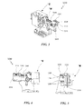
- FIG. 1 is a perspective view, with parts separated, of an application counter assembly according to an embodiment of the present disclosure
- FIG. 2 is a perspective view of the application counter assembly of FIG. 1 shown operatively connected to a side feed applicator;
- FIG. 3 is a perspective view of the application counter assembly of FIG. 1 shown operatively connected to an end feed applicator;
- FIG. 4 is a front elevational view of the side feed applicator of FIG. 2 including the application counter assembly of FIG. 1;
- FIG. 5 is a side elevational view of the side feed applicator of FIGS. 2 and 4 including the application counter assembly of FIG. 1;
- FIG. 6 is a rear elevational view of the side feed applicator of FIGS. 2, 4 and 5 including the applicator counter assembly of FIG. 1;
- FIG. 7 is an enlarged top plan view illustrating the connection of the applicator counter assembly of FIG. 1 to the applicator;
- FIG. is a bottom, perspective view illustrating the connection of the applicator counter assembly of FIG. 1 to the applicator;
- FIG. 9 is a perspective view, with parts separated, of an applicator counter assembly according to another embodiment of the present disclosure.
- FIG. 10 is a perspective view of the applicator counter assembly of FIG. 9 shown operatively connected to an end air feed applicator;
- FIG. 11 is a perspective view of the applicator counter assembly of FIG. 9 shown operatively connected to a side air feed applicator;
- FIG. 12 is an exploded, perspective view of the counter of the assembly of FIG. 1;
- FIG. 13 is a schematic illustration of the counter of FIG. 12.
- FIG. 14 is a schematic illustration of a reed switch.
- distal refers to that portion which is furthest from the user while the term “proximal” refers to that portion which is closest to the user.
- the applicator counter assembly of the present disclosure is a simple and inexpensive computer control device capable of storing information for terminal setup and capable of collecting data for a scheduled maintenance and calibration program.
- an applicator counter assembly in accordance with an embodiment of the present disclosure and for operative engagement with a machine and/or tool (e.g., an applicator or the like), is generally designated as 100.
- Applicator counter assembly 100 includes a counter 200, and a counter mounting kit 110 configured and adapted to selectively operatively connect counter 200 to a machine and/or tool "M".
- counter mounting kit 110 and counter 200 are configured for side attachment to machine and/or tool "M", as seen in FIG. 2, and/or end attachment to machine and/or tool "M”, as seen in FIG. 3.
- counter mounting kit 110 includes a counter mounting bracket 112 including at least one hole 114 formed therein for receiving a corresponding securing element 116 (e.g., a screw or the like) therethrough. Desirably, a pair of holes 114 is provided for receiving a pair of screws 116 for securing counter 200 thereto.
- Bracket 132 further includes at least one elongate slot 118 formed therein and extending at least substantially across the entire rear portion of bracket 112. Desirably, a pair of substantially parallel elongate slots 118 is formed in bracket 112. While a pair of parallel elongate slots 118 are shown and described, it is envisioned that any configuration aperture may be provided. Slots 118 enable the adjustment of and desired placement of counter 200 relative to machine "M". Each slot 118 is configured and dimensioned to receive a respective mounting element 120 (e.g., a screw) or the like.
- Counter mounting kit 110 further includes a guide 122 selectively mountable to bracket 112.
- Guide 122 includes at least one aperture formed in an upper surface thereof for receiving corresponding screws 120 extending through nuts 121' and elongate slots 118.
- Guide 122 further includes at least one mounting hole 124 formed therethrough for receiving a mounting screw 126 (see FIGS. 5-8).
- a pair of mounting holes 124 is provided.
- Mounting holes 124 and mounting screws 126 are used to secure guide 122 to machine and/or tool "M”.
- screws 120 extend through slots 118 and engage complementary holes 121 formed in a top surface of guide 122.
- Counter mounting kit 110 further includes an adjustment rod 130 slidably extending through an appropriately sized aperture 128 formed in guide 122. Desirably, adjustment rod 130 extends orthogonally through guide 122. Adjustment rod 130 includes a first end 130a and a second end 130b. First end 130a of adjustment rod 130 extends through aperture 128 formed in guide 122, and second end 130b of adjustment rod 130 is configured for operative engagement to a working element "W" of machine "M" (see FIG. 6).
- Adjustment rod 130 includes a threaded opening 132 formed in first end 130a thereof for receiving an adjustment screw 134.
- a magnet 136 i.e., a ring magnet
- a first locking element 138a i.e., a nut
- a second locking element 138b i.e., a nut
- second locking element 138b functions to fix the location of ring magnet 136 to counter 200 when working element "W" of machine “M” is in an idle condition.
- ring magnet 136 is disposed proximate a predetermined location of counter 200 (see FIGS. 6-8).
- a pair of spaced apart annular grooves 140 is formed in adjustment rod 130, between first end 130a and second end 130b.
- Annular grooves 140 are each configured and dimensioned to operatively receive a respective retaining ring 142.
- second end 130b of adjustment screw 130 extends through working element "W" of machine “M” and retaining rings 142 are disposed on either side of working element "W”. In this manner, adjustment rod 130 will axially translate in the direction of movement of working element "W”.
- a compression spring 144 is positioned about adjustment rod 130 and between guide 122 and a retaining ring 142. In this manner, compression spring 144 will bias adjustment rod 130, and in turn ring magnet 136 into magnetic engagement with counter 200 when working element "W" returns to the idle condition.
- ring magnet 136 In use, as will be described in greater detail below, when working element "W” of machine “M” is in an idle or first condition (see FIGS. 2-8), ring magnet 136 is positioned at a location for magnetic operative engagement with counter 200, i.e., ring magnet 136 magnetically draws or repels a complementary magnet or magnetically responsive material (not shown) in a first direction. When working element "W” of machine “M” is in a second or working condition (not shown), ring magnet 136 is positioned at a location to have no magnetic operative engagement with counter 200, i.e., ring magnet 136 does not magnetically draw or repel a complementary magnet or magnetically responsive material (not shown) in the first direction.
- counter mounting kit 110 is configured and adapted for connecting counter 200 to a machine "M” having an end air feed, as seen in FIG. 10, or a machine “M” having a side air feed, as seen in FIG. 11.
- Counter mounting kit 110 includes an L-shaped bracket 150 having a back wall portion 152 and a bottom wall portion 154.
- Back wall portion 152 of L-shaped bracket 150 includes at least one aperture 152a formed therein for receiving a mounting element 153, e.g., a screw (see FIGS. 10 and 11).
- Bottom wall portion 154 of L-shaped bracket 150 includes a plurality of holes 154a formed therein. Holes 154a are formed at locations which align with elongate slots 118 formed in bracket 112. Holes 154a are configured and sized to receive screws 120.
- bracket 112 is disposed on top of bottom wall portion 154 of L-shaped bracket 150.
- Counter mounting kit 110 further includes a clevis 160 which is securable to machine "M” and which is configured and adapted to support a pin or rod 162.
- Pin or rod 162 includes a magnet 164 disposed at an end thereof. Desirably, pin or rod 162 extends through holes 160b formed in arms 160a of clevis 160.
- a retaining ring 166 may be provided and used to engage an annular groove 162a formed in pin or rod 162 and preventing pin or rod 162 from sliding out of holes 160b of clevis 160.
- mounting kit 110 when counter mounting kit 110 is used to mount counter 200 to a machine "M" having an end air feed, as seen in FIG. 10, or a machine “M” having a side air feed, as seen in FIG. 11, mounting kit 110 is configured to position magnet 164 proximate a predetermined location of counter 200 when machine "M” is in the idle condition.
- magnet 164 In use, when working element "W” of machine “M” is in the idle of first condition, magnet 164 is positioned at a location for magnetic operative engagement with counter 200 (i.e., magnet 164 magnetically draws or repels a complementary magnet or magnetically responsive material in a first direction.
- magnet 164 When working clement “W” of machine “M” is in a second or working condition (not shown), magnet 164 is positioned at a location to have no magnetic operative engagement with counter 200, i.e., magnet 164 does not magnetically draw or repel a complementary magnet or magnetically responsive material in the first direction.
- Counter 200 includes a housing 202 having a rear-half portion 202a and a front-half portion 202b.
- Rear-half portion 202a and front-half portion 202b are joined together using any method or technique known by one having skill in the art, such as, for example, spot welding, adhering, fastening and the like.
- Front-half portion 202b of housing 202 defines a window 204 formed therein for exposing a display 206 disposed within housing 202.
- display 206 is an LCD (liquid crystal display) or any other graphic producing display available in the art.
- At least one connector 208 is provided for electrically connecting display 206 to a circuit board assembly 210.
- a pair of connectors 208 is used to electrically connect display 206 to circuit board assembly 210. It is envisioned that connectors 208 are "zebra-type" connectors.
- Counter 200 includes a circuit board assembly 210 mounted within housing 202 having half-sections 202a, 202b using mounting elements 203 (e.g., screws or the like).
- Circuit board assembly 210 includes a printed circuit board 212 supporting at least a microchip 214, a battery 216 or other energy source, a display controller 218, at least one reed or Hall effect switch 220 or any other magnetically responsive switch, an IrDA® controller 222 or any other data transmitting controller, and a storage element 224.
- Reed switches 220 are configured and adapted to activate and/or function upon exposure to magnetic forces and the like.
- reed switch 220 includes two identical flattened ferromagnetic reeds 220a, sealed in a dry inert-gas atmosphere within a capsule 220b, thereby protecting reeds 220a from contamination.
- Reeds 220a are sealed in capsule 220b in cantilever form so that their free ends overlap (as indicated by arrow "B") and are separated by a small gap 220c.
- reeds 220a become flux carriers in the magnetic circuit.
- each contacting of reeds 220a with one another represents a single count of operation of machine "M”.
- microchip 214 and storage element 224 may retain the following data fields: total count, permanent data; and tooling data.
- the permanent data may include information about the machine and/or tool "M", such as, for example, the date manufactured; the serial number; the part number; and the customer data.
- the tooling data may include information such as the part number, date, and cycle count for wire crimpers, insulation crimpers, anvils, sheer tools, maintenance data and the like.
- IrDA® controller 222 uses an IrDA®, built into circuit board assembly. IrDA® controller 222 enables creation of a wireless interface to a separate computer for data transfer.
- display 206 and IrDA® controller 222 are desirably normally in an "off" condition.
- a push-button 226, supported in front-half portion 202b of housing 202 is depressed.
- magnate 136 or 164 In use, as magnet 136 or 164 is approximated toward reed switch 220, the magnetic force generated by magnate 136 or 164 is strong enough to overcome the restoring force of reeds 220a and will draw reeds 220a together to complete an electrical circuit and register a single count of operation for machine "M".
- all of the counts registered are stored in storage element 224 of counter 200 and, if desired, processed and/or manipulated by microchip 214. The processes information is later transmitted, via IrDA®, controller 222 to an external, remote computer "C” (see FIG. 13). Alternatively, in another embodiment, all of the counts are transmitted immediately to computer "C" for storage and/or further processing and manipulating.
- applicator counter assembly 100 By using applicator counter assembly 100 to monitor, store and process data regarding the usage of machine and/or tool "M" (e.g., the count or number of times the machine and/or tool is used), the user is better able to predict and/or forecast when machine and/or tool maintenance or replacement will be necessary. In this manner, all the necessary replacement machines and/or tools may be acquired ahead of time, or all of the necessary repair equipment may be readied ahead of time in order to reduce the time machine and/or tool "M" is kept idle, i.e., downtime.
- machine and/or tool "M" e.g., the count or number of times the machine and/or tool is used
Landscapes
- Physics & Mathematics (AREA)
- General Physics & Mathematics (AREA)
- Engineering & Computer Science (AREA)
- Theoretical Computer Science (AREA)
- Electromagnetism (AREA)
- Coating Apparatus (AREA)
- Time Recorders, Dirve Recorders, Access Control (AREA)
- Portable Nailing Machines And Staplers (AREA)
- Catching Or Destruction (AREA)
- Manufacturing Of Electrical Connectors (AREA)
- Switches That Are Operated By Magnetic Or Electric Fields (AREA)
Abstract
Description
- The present disclosure relates to electronic devices and, more particularly, to electronic applicator counters for counting, recording and transmitting cycles of machines, tools and the like.
- Current devices and/or equipment operatively connected to applicators (e.g., machines and the like), used to count cycles and the like, are typically simple mechanical counters or electromechanical counters. Information and records regarding the maintenance of the applicator are kept at a location and/or in a device which is separate from the applicator counter itself. In other words, various numbers af cables and/or wires may extend from the applicator counter to a separate storing and/or recording device, where the cycles counted are kept and stored. Alternatively, an individual must inspect the applicator counter, at regular intervals, and manually record the information collected (e.g., cycles) and either enter that information into a separate device at that moment or enter that information into a separate device at a later time.
- Repetitive use of machines and tools results in machine or tooling wear. Accordingly, if continuous and meticulous records are kept and analyzed for the usage of the machine and/or tool, a user may be better able to predict and/or forecast when machine and/or tool maintenance or replacement will be necessary. In this manner, all the necessary replacement machines and/or tools may be acquired ahead of time, or all of the necessary repair equipment may be readied ahead of time in order to reduce the time the machine and/or tool is kept idle, i.e., downtime.
- The problem is that devices and/or equipment capable of counting cycles and other data associated with the operation of machines, tools and the like, as well as being capable of recording and/or storing the data for manipulation are either separate from the machine or require significant operator interface.
- The solution is provided by an electronic device or applicator counter of the present disclosure for counting, recording and transmitting cycles of machines, tools and the like. The applicator counter includes a housing defining at least one window, a display operatively disposed within the housing and visible through the window formed in the housing; and a circuit board assembly operatively disposed within the housing and in electrical contact with the display.
- The circuit board assembly includes a printed circuit board; a microchip supported on the printed circuit board far processing and manipulating information, an energy source supported on the printed circuit board for powering at least the display and the microchip; a storage element supported on the printed circuit board for storing information; and a magnetically responsive switch supported on the printed circuit board. The switch is configured to actuate in response to a magnetic force, whereby the circuit board assembly registers a count for each actuation (e.g., closing) of the switch.
- The circuit board may further include a data transmitting controller supported on the printed circuit board for transmitting information to a remote location. The applicator counter assembly further includes a counter mounting kit for mounting the applicator counter to the applicator.
- The invention will now be described by way of example with reference to the accompanying drawings in which:
- FIG. 1 is a perspective view, with parts separated, of an application counter assembly according to an embodiment of the present disclosure;
- FIG. 2 is a perspective view of the application counter assembly of FIG. 1 shown operatively connected to a side feed applicator;
- FIG. 3 is a perspective view of the application counter assembly of FIG. 1 shown operatively connected to an end feed applicator;
- FIG. 4 is a front elevational view of the side feed applicator of FIG. 2 including the application counter assembly of FIG. 1;
- FIG. 5 is a side elevational view of the side feed applicator of FIGS. 2 and 4 including the application counter assembly of FIG. 1;
- FIG. 6 is a rear elevational view of the side feed applicator of FIGS. 2, 4 and 5 including the applicator counter assembly of FIG. 1;
- FIG. 7 is an enlarged top plan view illustrating the connection of the applicator counter assembly of FIG. 1 to the applicator;
- FIG. is a bottom, perspective view illustrating the connection of the applicator counter assembly of FIG. 1 to the applicator;
- FIG. 9 is a perspective view, with parts separated, of an applicator counter assembly according to another embodiment of the present disclosure;
- FIG. 10 is a perspective view of the applicator counter assembly of FIG. 9 shown operatively connected to an end air feed applicator;
- FIG. 11 is a perspective view of the applicator counter assembly of FIG. 9 shown operatively connected to a side air feed applicator;
- FIG. 12 is an exploded, perspective view of the counter of the assembly of FIG. 1;
- FIG. 13 is a schematic illustration of the counter of FIG. 12; and
- FIG. 14 is a schematic illustration of a reed switch.
- Embodiments of the presently disclosed applicator counter assembly will now be described in detail with reference to the drawing figures wherein like reference numerals identify similar or identical elements. As used herein and as traditional, the term "distal" refers to that portion which is furthest from the user while the term "proximal" refers to that portion which is closest to the user.
- The applicator counter assembly of the present disclosure is a simple and inexpensive computer control device capable of storing information for terminal setup and capable of collecting data for a scheduled maintenance and calibration program.
- Referring initially to FIGS. 1-8, an applicator counter assembly, in accordance with an embodiment of the present disclosure and for operative engagement with a machine and/or tool (e.g., an applicator or the like), is generally designated as 100.
Applicator counter assembly 100 includes acounter 200, and acounter mounting kit 110 configured and adapted to selectively operatively connectcounter 200 to a machine and/or tool "M". Desirably,counter mounting kit 110 andcounter 200 are configured for side attachment to machine and/or tool "M", as seen in FIG. 2, and/or end attachment to machine and/or tool "M", as seen in FIG. 3. - As seen in FIG. 1,
counter mounting kit 110 includes acounter mounting bracket 112 including at least onehole 114 formed therein for receiving a corresponding securing element 116 (e.g., a screw or the like) therethrough. Desirably, a pair ofholes 114 is provided for receiving a pair ofscrews 116 for securingcounter 200 thereto.Bracket 132 further includes at least oneelongate slot 118 formed therein and extending at least substantially across the entire rear portion ofbracket 112. Desirably, a pair of substantially parallelelongate slots 118 is formed inbracket 112. While a pair of parallelelongate slots 118 are shown and described, it is envisioned that any configuration aperture may be provided.Slots 118 enable the adjustment of and desired placement ofcounter 200 relative to machine "M". Eachslot 118 is configured and dimensioned to receive a respective mounting element 120 (e.g., a screw) or the like. -
Counter mounting kit 110 further includes aguide 122 selectively mountable tobracket 112.Guide 122 includes at least one aperture formed in an upper surface thereof for receivingcorresponding screws 120 extending through nuts 121' andelongate slots 118.Guide 122 further includes at least onemounting hole 124 formed therethrough for receiving a mounting screw 126 (see FIGS. 5-8). Desirably, a pair ofmounting holes 124 is provided.Mounting holes 124 and mountingscrews 126 are used to secureguide 122 to machine and/or tool "M". Desirably,screws 120 extend throughslots 118 and engagecomplementary holes 121 formed in a top surface ofguide 122. -
Counter mounting kit 110 further includes anadjustment rod 130 slidably extending through an appropriately sizedaperture 128 formed inguide 122. Desirably,adjustment rod 130 extends orthogonally throughguide 122.Adjustment rod 130 includes afirst end 130a and a second end 130b.First end 130a ofadjustment rod 130 extends throughaperture 128 formed inguide 122, and second end 130b ofadjustment rod 130 is configured for operative engagement to a working element "W" of machine "M" (see FIG. 6). -
Adjustment rod 130 includes a threadedopening 132 formed infirst end 130a thereof for receiving anadjustment screw 134. A magnet 136 (i.e., a ring magnet) is positioned onshaft portion 134b ofadjustment screw 134, againsthead portion 134a ofadjustment screw 134. Afirst locking element 138a (i.e., a nut) may be used to securering magnet 136 againsthead portion 134a ofadjustment screw 134. Asecond locking element 138b (i.e., a nut) may be used to fix the location ofring magnet 136 relative toadjustment rod 130. More particularly, as will be described in greater detail below,second locking element 138b functions to fix the location ofring magnet 136 to counter 200 when working element "W" of machine "M" is in an idle condition. Desirably, when working element "W" of machine "M" is in the idle condition,ring magnet 136 is disposed proximate a predetermined location of counter 200 (see FIGS. 6-8). - As seen in FIG. 1, a pair of spaced apart
annular grooves 140 is formed inadjustment rod 130, betweenfirst end 130a and second end 130b.Annular grooves 140 are each configured and dimensioned to operatively receive a respectiveretaining ring 142. Desirably, second end 130b ofadjustment screw 130 extends through working element "W" of machine "M" andretaining rings 142 are disposed on either side of working element "W". In this manner,adjustment rod 130 will axially translate in the direction of movement of working element "W". Desirably, acompression spring 144 is positioned aboutadjustment rod 130 and betweenguide 122 and aretaining ring 142. In this manner,compression spring 144 will biasadjustment rod 130, and inturn ring magnet 136 into magnetic engagement withcounter 200 when working element "W" returns to the idle condition. - In use, as will be described in greater detail below, when working element "W" of machine "M" is in an idle or first condition (see FIGS. 2-8),
ring magnet 136 is positioned at a location for magnetic operative engagement withcounter 200, i.e.,ring magnet 136 magnetically draws or repels a complementary magnet or magnetically responsive material (not shown) in a first direction. When working element "W" of machine "M" is in a second or working condition (not shown),ring magnet 136 is positioned at a location to have no magnetic operative engagement withcounter 200, i.e.,ring magnet 136 does not magnetically draw or repel a complementary magnet or magnetically responsive material (not shown) in the first direction. - Turning now to FIGS. 9-11, counter mounting
kit 110 is configured and adapted for connecting counter 200 to a machine "M" having an end air feed, as seen in FIG. 10, or a machine "M" having a side air feed, as seen in FIG. 11. Counter mountingkit 110 includes an L-shapedbracket 150 having aback wall portion 152 and abottom wall portion 154. Backwall portion 152 of L-shapedbracket 150 includes at least one aperture 152a formed therein for receiving a mountingelement 153, e.g., a screw (see FIGS. 10 and 11).Bottom wall portion 154 of L-shapedbracket 150 includes a plurality of holes 154a formed therein. Holes 154a are formed at locations which align withelongate slots 118 formed inbracket 112. Holes 154a are configured and sized to receivescrews 120. In use,bracket 112 is disposed on top ofbottom wall portion 154 of L-shapedbracket 150. - Counter mounting
kit 110 further includes aclevis 160 which is securable to machine "M" and which is configured and adapted to support a pin orrod 162. Pin orrod 162 includes amagnet 164 disposed at an end thereof. Desirably, pin orrod 162 extends throughholes 160b formed inarms 160a ofclevis 160. A retainingring 166 may be provided and used to engage anannular groove 162a formed in pin orrod 162 and preventing pin orrod 162 from sliding out ofholes 160b ofclevis 160. - Desirably, when counter mounting
kit 110 is used to mount counter 200 to a machine "M" having an end air feed, as seen in FIG. 10, or a machine "M" having a side air feed, as seen in FIG. 11, mountingkit 110 is configured to positionmagnet 164 proximate a predetermined location ofcounter 200 when machine "M" is in the idle condition. In use, when working element "W" of machine "M" is in the idle of first condition,magnet 164 is positioned at a location for magnetic operative engagement with counter 200 (i.e.,magnet 164 magnetically draws or repels a complementary magnet or magnetically responsive material in a first direction. When working clement "W" of machine "M" is in a second or working condition (not shown),magnet 164 is positioned at a location to have no magnetic operative engagement withcounter 200, i.e.,magnet 164 does not magnetically draw or repel a complementary magnet or magnetically responsive material in the first direction. - Turning now to FIGS. 12 and 13, a detailed discussion of
counter 200 is provided.Counter 200 includes ahousing 202 having a rear-half portion 202a and a front-half portion 202b. Rear-half portion 202a and front-half portion 202b are joined together using any method or technique known by one having skill in the art, such as, for example, spot welding, adhering, fastening and the like. Front-half portion 202b ofhousing 202 defines awindow 204 formed therein for exposing adisplay 206 disposed withinhousing 202. Desirably,display 206 is an LCD (liquid crystal display) or any other graphic producing display available in the art. - At least one
connector 208 is provided for electrically connectingdisplay 206 to acircuit board assembly 210. Preferably, a pair ofconnectors 208 is used to electrically connectdisplay 206 tocircuit board assembly 210. It is envisioned thatconnectors 208 are "zebra-type" connectors. -
Counter 200 includes acircuit board assembly 210 mounted withinhousing 202 having half-sections 202a, 202b using mounting elements 203 (e.g., screws or the likeCircuit board assembly 210 includes a printedcircuit board 212 supporting at least amicrochip 214, abattery 216 or other energy source, adisplay controller 218, at least one reed orHall effect switch 220 or any other magnetically responsive switch, anIrDA® controller 222 or any other data transmitting controller, and astorage element 224. - Reed switches 220 are configured and adapted to activate and/or function upon exposure to magnetic forces and the like. For example, as seen in FIG. 14,
reed switch 220 includes two identical flattenedferromagnetic reeds 220a, sealed in a dry inert-gas atmosphere within acapsule 220b, thereby protectingreeds 220a from contamination.Reeds 220a are sealed incapsule 220b in cantilever form so that their free ends overlap (as indicated by arrow "B") and are separated by asmall gap 220c. In operation, when a magnetic force is generated parallel toreed switch 220,reeds 220a become flux carriers in the magnetic circuit. The overlapping ends ofreeds 220a become opposite magnetic poles, which attract each other. If the magnetic force between the poles is strong enough to overcome the restoring force of reeds 220a (as indicated by arrows "A"),reeds 220a will be drawn together and complete an electrical circuit. In the case ofcounter 200, each contacting ofreeds 220a with one another represents a single count of operation of machine "M". - It is envisioned that
microchip 214 andstorage element 224 may retain the following data fields: total count, permanent data; and tooling data. The permanent data may include information about the machine and/or tool "M", such as, for example, the date manufactured; the serial number; the part number; and the customer data. The tooling data may include information such as the part number, date, and cycle count for wire crimpers, insulation crimpers, anvils, sheer tools, maintenance data and the like. -
IrDA® controller 222 uses an IrDA®, built into circuit board assembly.IrDA® controller 222 enables creation of a wireless interface to a separate computer for data transfer. - To conserve power,
display 206 andIrDA® controller 222 are desirably normally in an "off" condition. To activatedisplay 206 andIrDA® controller 222, a push-button 226, supported in front-half portion 202b ofhousing 202 is depressed. - In use, as
magnet reed switch 220, the magnetic force generated bymagnate reeds 220a and will drawreeds 220a together to complete an electrical circuit and register a single count of operation for machine "M". In one embodiment, all of the counts registered are stored instorage element 224 ofcounter 200 and, if desired, processed and/or manipulated bymicrochip 214. The processes information is later transmitted, via IrDA®,controller 222 to an external, remote computer "C" (see FIG. 13). Alternatively, in another embodiment, all of the counts are transmitted immediately to computer "C" for storage and/or further processing and manipulating. - By using
applicator counter assembly 100 to monitor, store and process data regarding the usage of machine and/or tool "M" (e.g., the count or number of times the machine and/or tool is used), the user is better able to predict and/or forecast when machine and/or tool maintenance or replacement will be necessary. In this manner, all the necessary replacement machines and/or tools may be acquired ahead of time, or all of the necessary repair equipment may be readied ahead of time in order to reduce the time machine and/or tool "M" is kept idle, i.e., downtime. - It is to be understood that the foregoing description is merely a disclosure of particular embodiments and is no way intended to limit the scope of the invention. Other possible modifications will be apparent to those skilled in the art and all modifications will be apparent to those in the art and all modifications are to be defined by the following claims.
Claims (10)
- An applicator counter (200) comprising: a housing (202) defining at least one window (204); a display (206) operatively disposed within the housing (202) and visible through the window (204) formed in the housing (202); and characterized by:a circuit board assembly (210) operatively disposed within the housing (202) and in electrical contact with the display (206), the circuit board assembly (210) including:a printed circuit board (212);a microchip (214) supported on the printed circuit board (212) for processing and manipulating information;an energy source (216) supported on the printed circuit board (212) for powering at least the display (206) and the microchip (214);a storage element (224) supported on the printed circuit board (212) for storing information; anda magnetically responsive switch (220) supported on the printed circuit board (212), the switch (220) being actuated in response to a magnetic force, whereby the circuit board assembly (210) registers a count for each actuation of the switch (220).
- The applicator counter according to claim 1, wherein the magnetically responsive switch (220) is a reed switch.
- The applicator counter according to claim 2, wherein the circuit board assembly (210) includes at least a pair of reed switches (220) positioned at opposing sides thereof.
- The applicator counter (200) according to any preceding claim, wherein the circuit board assembly (210) further comprises a data transmitting controller (222) supported on the printed circuit board (212) for transmitting information to a remote location.
- An applicator counter assembly (100) for operative association with an applicator, the applicator counter assembly (110) being characterized by:an applicator counter (200) for counting, recording and transmitting cycles of the applicator, the applicator counter (200) including a magnetically responsive switch (220) configured to actuate in response to a magnetic force, whereby the applicator counter (200) registers a count for each actuation of the switch (220); anda counter mounting kit (110) for mounting the applicator counter (200) to the applicator, the counter mounting kit including:a bracket (112) configured to interconnect the applicator counter (200) and the applicator; anda magnet (136, 164) operatively supportable on a working element (w) of the applicator; the magnet (136, 164) having a first position, corresponding to when the working element (w) is in an idle condition, in which the magnet (136, 164) does not cause the magnetically responsive switch to actuate, and a second position, corresponding to when the working element (w) is in an active condition, in which the magnet (136, 164) causes the magnetically responsive switch (220) to actuate, wherein the applicator counter (200) registers each count.
- The applicator counter assembly (100) according to claim 5, wherein the counter mounting kit (110) further includes:a guide (122) selectively mountable to the bracket (112); anda rod (130) extending through the guide (122) and configured to support the magnet (136, 164) thereon.
- The applicator counter assembly (100) according to claim 6, wherein the rod (130) is selectively connectable to the working element (w) of the machine, wherein movement of the working element results in movement of the rod.
- The applicator counter assembly (100) according to claim 7, wherein the bracket (112) is configured to enable adjustment of the location of the applicator counter.
- The applicator counter assembly (100) according to claim 8, wherein the guide (122) is a clevis (160) and the rod (130) extends through arms of the clevis (160).
- The applicator counter assembly according to claim 9, wherein when the working element of the machine is in an active condition, the magnet (136, 164) is positioned at a magnetically effective distance relative to the magnetically responsive switch (220).
Applications Claiming Priority (1)
| Application Number | Priority Date | Filing Date | Title |
|---|---|---|---|
| US11/091,097 US7466788B2 (en) | 2005-03-28 | 2005-03-28 | Electronic applicator counter |
Publications (3)
| Publication Number | Publication Date |
|---|---|
| EP1708145A2 true EP1708145A2 (en) | 2006-10-04 |
| EP1708145A3 EP1708145A3 (en) | 2007-08-01 |
| EP1708145B1 EP1708145B1 (en) | 2009-01-07 |
Family
ID=36617184
Family Applications (1)
| Application Number | Title | Priority Date | Filing Date |
|---|---|---|---|
| EP06111799A Ceased EP1708145B1 (en) | 2005-03-28 | 2006-03-28 | Electronic application counter |
Country Status (4)
| Country | Link |
|---|---|
| US (1) | US7466788B2 (en) |
| EP (1) | EP1708145B1 (en) |
| CN (1) | CN1841414B (en) |
| DE (1) | DE602006004632D1 (en) |
Cited By (1)
| Publication number | Priority date | Publication date | Assignee | Title |
|---|---|---|---|---|
| IT202100026018A1 (en) * | 2021-10-11 | 2023-04-11 | Datainabox S R L | CYCLE DETECTOR FOR MINI APPLICATORS |
Families Citing this family (6)
| Publication number | Priority date | Publication date | Assignee | Title |
|---|---|---|---|---|
| DE102005023232A1 (en) * | 2005-05-20 | 2006-11-23 | Krauss-Maffei Kunststofftechnik Gmbh | Integrated shot counter for mixing head |
| US8270513B2 (en) * | 2006-05-31 | 2012-09-18 | Cobham Defense Electronic Systems Corporation | Fully saturated multi-tone transceiver |
| WO2014106279A1 (en) * | 2012-12-31 | 2014-07-03 | M-I Llc | Choke calibration, position, and/or time display |
| US11614341B2 (en) | 2018-06-14 | 2023-03-28 | Analog Devices International Unlimited Company | Methods and devices for using multi-turn magnetic sensors with extended magnetic windows |
| CN112923984A (en) * | 2019-10-29 | 2021-06-08 | 张志坤 | Impeller type non-magnetic sensor flowmeter and method |
| FR3167707A1 (en) * | 2024-10-23 | 2026-04-24 | Integra Metering Sas | Electronic control unit, including a flow meter and a method for detecting an actuator of this flow meter |
Citations (1)
| Publication number | Priority date | Publication date | Assignee | Title |
|---|---|---|---|---|
| DE10045207A1 (en) | 2000-09-13 | 2002-03-28 | Abb Patent Gmbh | Water meter with operating bowl for holding mechanical metering device, has an electronic module plate connected to an upper bearing plate to let the module carry a reed switch to register ciphering roller's speed |
Family Cites Families (15)
| Publication number | Priority date | Publication date | Assignee | Title |
|---|---|---|---|---|
| US4140897A (en) | 1977-10-25 | 1979-02-20 | Guerra David J | Electronic digital sequential counters |
| US4265370A (en) * | 1979-03-22 | 1981-05-05 | Reilly David H | Portable liquid metering device |
| JPS57155696A (en) * | 1981-03-23 | 1982-09-25 | Hitachi Ltd | Data processor for automobile |
| US4726044A (en) * | 1986-10-20 | 1988-02-16 | Fred P. Perna | Writing instrument with solar-powered electronic counting and liquid cyrstal display |
| US4768209A (en) * | 1987-05-28 | 1988-08-30 | Yu Ching Yu | Magnetic induction counting device |
| US5117444A (en) * | 1990-07-30 | 1992-05-26 | W. Ron Sutton | High accuracy pedometer and calibration method |
| CN2073866U (en) * | 1990-08-07 | 1991-03-27 | 上海市房屋科学研究所 | Recording instrument for number of travels of lift |
| US5307524A (en) * | 1992-03-25 | 1994-05-03 | Veal Bennie N | Automatic toilet seat device |
| DE4442193A1 (en) | 1994-11-15 | 1996-05-23 | Allmess Schlumberger Gmbh | Electronic counter module for water meter |
| CA2141092C (en) * | 1995-01-25 | 1999-01-05 | James F. White | Communication between components of a machine |
| US5625659A (en) * | 1995-05-19 | 1997-04-29 | Gojo Industries, Inc. | Method and apparatus for electronically measuring dispenser usage |
| DE19736057A1 (en) | 1997-08-20 | 1999-02-25 | Horst Hartmann | Tool movement counting method |
| US6404837B1 (en) * | 1998-06-11 | 2002-06-11 | Ecolab, Inc. | Usage competent hand soap dispenser with data collection and display capabilities |
| DE10023425A1 (en) | 2000-05-12 | 2001-11-22 | Ewe Tel Gmbh | Meter for e.g. electricity, gas, water has mechanical reading device that is provided to display which is wired to evaluation device |
| GB2377273A (en) * | 2001-05-09 | 2003-01-08 | Graco Childrens Prod Inc | Pushchair with programmable exercise information module |
-
2005
- 2005-03-28 US US11/091,097 patent/US7466788B2/en not_active Expired - Lifetime
-
2006
- 2006-03-28 EP EP06111799A patent/EP1708145B1/en not_active Ceased
- 2006-03-28 DE DE602006004632T patent/DE602006004632D1/en not_active Expired - Lifetime
- 2006-03-28 CN CN2006100794177A patent/CN1841414B/en not_active Expired - Fee Related
Patent Citations (1)
| Publication number | Priority date | Publication date | Assignee | Title |
|---|---|---|---|---|
| DE10045207A1 (en) | 2000-09-13 | 2002-03-28 | Abb Patent Gmbh | Water meter with operating bowl for holding mechanical metering device, has an electronic module plate connected to an upper bearing plate to let the module carry a reed switch to register ciphering roller's speed |
Cited By (2)
| Publication number | Priority date | Publication date | Assignee | Title |
|---|---|---|---|---|
| IT202100026018A1 (en) * | 2021-10-11 | 2023-04-11 | Datainabox S R L | CYCLE DETECTOR FOR MINI APPLICATORS |
| EP4163824A1 (en) * | 2021-10-11 | 2023-04-12 | Datainabox S.r.l. | A cycle detector device for automatic crimping tools |
Also Published As
| Publication number | Publication date |
|---|---|
| EP1708145B1 (en) | 2009-01-07 |
| CN1841414B (en) | 2010-05-12 |
| US7466788B2 (en) | 2008-12-16 |
| DE602006004632D1 (en) | 2009-02-26 |
| US20060222141A1 (en) | 2006-10-05 |
| EP1708145A3 (en) | 2007-08-01 |
| CN1841414A (en) | 2006-10-04 |
Similar Documents
| Publication | Publication Date | Title |
|---|---|---|
| EP1708145B1 (en) | Electronic application counter | |
| US5701110A (en) | Circuit breaker accessory module | |
| US20080094764A1 (en) | Power plug with leakage current detection and protection circuit | |
| CN108598742B (en) | Card holder assembly, electronic device and control method thereof | |
| US6217370B1 (en) | Circuit breaker accessory module terminal plug | |
| CN101105688A (en) | Assembly work instruction device and assembly work instruction method | |
| EP3780060A1 (en) | Pluggable connecting device for contactor and contactor | |
| CN111463612B (en) | Leakage protection device | |
| US5836441A (en) | Circuit breaker accessory module actuators | |
| JP6656087B2 (en) | Protective relay | |
| WO2016038435A1 (en) | Wiring device and wiring system | |
| US6563408B1 (en) | Diagnostic relay | |
| JP2019102155A (en) | Erroneous operation prevention cover | |
| EP1081776A3 (en) | Method and arrangement for anticipating disengagement moment of battery package of battery-operated electronic device, and battery-operated electronic device | |
| KR200441990Y1 (en) | Conductor connection device of magnetic contactor | |
| US6483717B1 (en) | Switch integral to a latch assembly | |
| CN1078008C (en) | Circuit breaker | |
| TWI790251B (en) | Testing apparatus and handles for testing apparatus | |
| CN223758262U (en) | Magnetic switch | |
| JPH0342720B2 (en) | ||
| DE59404211D1 (en) | Monitoring device for status detection in electromechanical circuit breakers | |
| JP2500838Y2 (en) | Earth leakage circuit breaker | |
| WO2004109736A1 (en) | Contactor and switch | |
| US6853560B2 (en) | Limited movement system for motor switch mounted thermo-protector | |
| JP3092873U (en) | Short-circuit structure of the wiring part on the substrate of the pickup and short-circuit structure of the wiring part on the substrate |
Legal Events
| Date | Code | Title | Description |
|---|---|---|---|
| PUAI | Public reference made under article 153(3) epc to a published international application that has entered the european phase |
Free format text: ORIGINAL CODE: 0009012 |
|
| AK | Designated contracting states |
Kind code of ref document: A2 Designated state(s): AT BE BG CH CY CZ DE DK EE ES FI FR GB GR HU IE IS IT LI LT LU LV MC NL PL PT RO SE SI SK TR |
|
| AX | Request for extension of the european patent |
Extension state: AL BA HR MK YU |
|
| PUAL | Search report despatched |
Free format text: ORIGINAL CODE: 0009013 |
|
| AK | Designated contracting states |
Kind code of ref document: A3 Designated state(s): AT BE BG CH CY CZ DE DK EE ES FI FR GB GR HU IE IS IT LI LT LU LV MC NL PL PT RO SE SI SK TR |
|
| AX | Request for extension of the european patent |
Extension state: AL BA HR MK YU |
|
| RIC1 | Information provided on ipc code assigned before grant |
Ipc: G07C 3/00 20060101AFI20060714BHEP Ipc: G01F 1/075 20060101ALI20070626BHEP |
|
| 17P | Request for examination filed |
Effective date: 20071108 |
|
| 17Q | First examination report despatched |
Effective date: 20071213 |
|
| AKX | Designation fees paid |
Designated state(s): DE GB IT |
|
| GRAP | Despatch of communication of intention to grant a patent |
Free format text: ORIGINAL CODE: EPIDOSNIGR1 |
|
| GRAS | Grant fee paid |
Free format text: ORIGINAL CODE: EPIDOSNIGR3 |
|
| GRAA | (expected) grant |
Free format text: ORIGINAL CODE: 0009210 |
|
| AK | Designated contracting states |
Kind code of ref document: B1 Designated state(s): DE GB IT |
|
| REG | Reference to a national code |
Ref country code: GB Ref legal event code: FG4D |
|
| REF | Corresponds to: |
Ref document number: 602006004632 Country of ref document: DE Date of ref document: 20090226 Kind code of ref document: P |
|
| PLBE | No opposition filed within time limit |
Free format text: ORIGINAL CODE: 0009261 |
|
| STAA | Information on the status of an ep patent application or granted ep patent |
Free format text: STATUS: NO OPPOSITION FILED WITHIN TIME LIMIT |
|
| 26N | No opposition filed |
Effective date: 20091008 |
|
| REG | Reference to a national code |
Ref country code: DE Ref legal event code: R082 Ref document number: 602006004632 Country of ref document: DE Representative=s name: MARKS & CLERK (LUXEMBOURG) LLP, LU Ref country code: DE Ref legal event code: R081 Ref document number: 602006004632 Country of ref document: DE Owner name: TE CONNECTIVITY CORPORATION, BERWYN, US Free format text: FORMER OWNER: TYCO ELECTRONICS CORP., MIDDLETOWN, PA., US |
|
| PGFP | Annual fee paid to national office [announced via postgrant information from national office to epo] |
Ref country code: GB Payment date: 20200318 Year of fee payment: 15 Ref country code: DE Payment date: 20200317 Year of fee payment: 15 Ref country code: IT Payment date: 20200221 Year of fee payment: 15 |
|
| REG | Reference to a national code |
Ref country code: DE Ref legal event code: R119 Ref document number: 602006004632 Country of ref document: DE |
|
| GBPC | Gb: european patent ceased through non-payment of renewal fee |
Effective date: 20210328 |
|
| PG25 | Lapsed in a contracting state [announced via postgrant information from national office to epo] |
Ref country code: GB Free format text: LAPSE BECAUSE OF NON-PAYMENT OF DUE FEES Effective date: 20210328 Ref country code: DE Free format text: LAPSE BECAUSE OF NON-PAYMENT OF DUE FEES Effective date: 20211001 |
|
| PG25 | Lapsed in a contracting state [announced via postgrant information from national office to epo] |
Ref country code: IT Free format text: LAPSE BECAUSE OF NON-PAYMENT OF DUE FEES Effective date: 20210328 |