EP1707828A1 - Thread insert with improved removability - Google Patents
Thread insert with improved removability Download PDFInfo
- Publication number
- EP1707828A1 EP1707828A1 EP06111996A EP06111996A EP1707828A1 EP 1707828 A1 EP1707828 A1 EP 1707828A1 EP 06111996 A EP06111996 A EP 06111996A EP 06111996 A EP06111996 A EP 06111996A EP 1707828 A1 EP1707828 A1 EP 1707828A1
- Authority
- EP
- European Patent Office
- Prior art keywords
- coil
- end section
- insert
- coil end
- notch
- Prior art date
- Legal status (The legal status is an assumption and is not a legal conclusion. Google has not performed a legal analysis and makes no representation as to the accuracy of the status listed.)
- Withdrawn
Links
Images


Classifications
-
- F—MECHANICAL ENGINEERING; LIGHTING; HEATING; WEAPONS; BLASTING
- F16—ENGINEERING ELEMENTS AND UNITS; GENERAL MEASURES FOR PRODUCING AND MAINTAINING EFFECTIVE FUNCTIONING OF MACHINES OR INSTALLATIONS; THERMAL INSULATION IN GENERAL
- F16B—DEVICES FOR FASTENING OR SECURING CONSTRUCTIONAL ELEMENTS OR MACHINE PARTS TOGETHER, e.g. NAILS, BOLTS, CIRCLIPS, CLAMPS, CLIPS OR WEDGES; JOINTS OR JOINTING
- F16B37/00—Nuts or like thread-engaging members
- F16B37/12—Nuts or like thread-engaging members with thread-engaging surfaces formed by inserted coil-springs, discs, or the like; Independent pieces of wound wire used as nuts; Threaded inserts for holes
Definitions
- the present invention relates in general to thread insert members and more specifically to helical coil shaped thread inserts insertable into an aperture of a relatively soft material to provide a female thread for subsequent insertion of a screw or bolt.
- Thread inserts having a generally helical shape are commonly used to create a receiving thread for subsequent insertion of a screw or bolt into a relatively soft receiving material such as polymeric material or soft metals such as aluminum or magnesium, etc.
- An aperture is pre-tapped in the receiving material to receive the helical insert.
- the helical insert or "coil” includes a plurality of both outside and inside surface areas acting as screw threads.
- a tang which is an extension of the coil extends radially inwardly from a coil section at a leading end of the coil and is provided for grasping by an insertion tool. Using the insertion tool and tang, the coil is threaded into the aperture, the coil outer surfaces engaging the tapped threads of the aperture. The tang can then be broken off by material failure at a notch pre-formed at a junction of the tang and the helical coil.
- the coil inner surfaces then provide engagement surfaces for receiving the threads of a screw, bolt or other fastener.
- Known helical coil designs provide retention strength or resistance to removal by sheared ends provided at both ends of the coil which bite into the softer receiving material when removal of the coil is attempted or a fastener is rotated into the coil.
- "insert ends” having no chamfers together with the sheared ends are used. Removal of coils is often required, for example to remove and/or replace the fastener during maintenance, or if the coil is damaged or is installed improperly.
- the softer receiving material is susceptible to damage. When the receiving material is a casting or complex part, the cost to replace the damaged part can be excessive.
- Coil designs are known which assist in removal of the coil, for example United States Patent 6,171,040 to Sato .
- Sato discloses a pair of notches 10 which are formed at a back end portion of the coil and include contact surfaces 10b for engagement by a tool such as a bladed screw driver.
- Sato also discloses a center flat surface 20 having chamfered surfaces 15, 16, 17 and 18.
- the disadvantage of the Sato and other known designs is that damage to the internal threads of the receiving material aperture can still occur when the coil is backed out,
- a tanged screw thread insert with improved removability of the present invention includes a helical-shaped insert having a plurality of coil sections, including opposing first and second coil end sections. A continuously curved surface is created at a rounded distal end of the second coil end section. A tangent point is created where the curved surface tangentially meets an outer surface of the second coil end section.
- a thread insert includes a helical-shaped insert defming a plurality of coil sections including opposing first and second coil end sections.
- the coil sections each have an inner surface and an outer surface, the inner and outer surfaces each having a thread shape.
- the outer surface of each of the coil sections are aligned to create a substantially constant diameter coil body.
- a removable tang extends radially inward from the first coil end section.
- a continuously curved surface is created at a rounded distal end of the second coil end section.
- a tangent point is created where the curved surface tangentially meets the outer surface of the second coil end section.
- a first notch is disposed in the first coil end section proximate to a tang connection and positioned between the inner and outer surfaces.
- the first notch is operable to create a failure point in the first coil end section for removal of the tang.
- a second notch is created in the second coil end section proximate to the continuously curved surface, the second notch having a contact surface operable to assist in removal of the insert from an installed position.
- a method for creating a thread insert includes creating a continuously curved surface at a rounded distal end of the second coil end section. The method further includes blending the continuously curved surface tangentially into an outer surface of the second coil end section to operably create a tangent point.
- a tanged screw thread insert with improved removability of the present invention provides several advantages. By retaining a substantially constant outside diameter of the individual coil segments, removal of the coil presents a substantially constant contact diameter against the threads of the receiving member, which reduces the possibility of an out-of-round coil segment causing frictional damage to the threads. By providing a continuously curving end surface at a distal end of the coil second end segment, a smooth surface is presented during removal of the insert which reduces the chance of frictional damage to the threads of the receiving member.
- Figure 1 is a cross sectional view showing a tanged screw thread insert with improved removability of the present invention inserted into a receiving member and having a threaded fastener partially inserted therein;
- Figure 2 is a top plan view of the tanged screw thread insert of the present invention.
- Figure 3 is a side elevational view of the insert of Figure 2;
- Figure 4 is a bottom plan view of the insert of Figure 1;
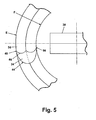
- Figure 5 is a top plan view of a continuous curved surface created at a distal end of a tanged screw thread insert of the present invention.
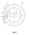
- Figure 6 is a top plan view of another preferred embodiment of a tanged screw thread insert of the present invention.
- an assembly 10 includes a helical insert 12 frictionally and rotatably received within a receiving member 14.
- Receiving member 14 can be a plate or sheet, a casting or molding, etc.
- Materials for receiving member 14 which benefit from the use of an insert 12 are generally materials including polymeric materials or the "soft" metals such as copper, aluminum, magnesium, etc., which do not have a tensile strength sufficient to prevent tear-out of a fastener 16 if fastener 16 is engaged only with receiving member 14.
- Insert 12 is therefore made of a higher tensile strength and harder material than receiving member 14, such as a steel, including stainless or spring steel.
- Fastener 16 can be any type of threaded fastener such as a screw or bolt, etc. In exemplary use, fastener 16 can provide hold-down capability to engage another item (not shown) to receiving member 14, or can act as an electrical contact post or electrical connection for receiving member 14.
- Insert 12 is generally completely received within a thickness "A" of receiving member 14 in a general direction "B".
- Insert 12 includes a continuous, helical-shaped coil, herein described for simplicity as a plurality of coil sections 18.
- Coil sections 18 each include an outer surface 20 having a thread-shape which engage a plurality of receiving threads 22 pre-tapped or formed in receiving member 14.
- Coil sections 18 each also include an inner surface 24 which are thread-shaped and sized to engage a plurality of threads 26 of fastener 16.
- Insert 12, fastener 16 and receiving threads 22 are coaxially aligned on a longitudinal axis 28.
- Longitudinal axis 28 is preferably aligned substantially perpendicular to at least a receiving face 29 of receiving member 14, but can be angled with respect to receiving face 29 or a central axis through receiving member 14 if receiving member 14 is formed in a curved shape.
- a tang 30 connects to and extends radially inward from a first coil end section 32 of coil sections 18.
- insert 12 is installed in a clockwise direction “C” and removed in a counterclockwise direction “D".
- Directions "C” and “D” can also be reversed if a reverse or left-hand threaded insert 12 is desired.
- Each of coil sections 18 have an outer diameter “E” defined by outer surface 20, and an inner diameter “F” defined by inner surface 24.
- Outer diameter “E” is sized to frictionally engage with receiving threads 22.
- Inner diameter "F” is sized to permit inner surfaces 24 to receive and engage threads 26.
- a finished end 34 is created at a distal end of a coil second end section 36.
- Coil second end section 36 is oppositely positioned from coil first end section 32.
- Finished end 34 is created in a separate operation such as by grinding, lapping, cold-heading, milling, etc.
- Tang 30 is preferably created by bending a portion of coil first end section 32 radially inward and substantially perpendicular to longitudinal axis 28 until tang 30 is coaxial to a first radial axis 38.
- First radial axis 38 is oriented substantially perpendicular to a second radial axis 40. Both first and second radial axes 38, 40 intersect at longitudinal axis 28.
- a deformation or notch 42 preferably a V-shaped notch is also created in coil first end section 32 proximate to the tang 30.
- insert 12 has a total height "G" which is preferably less than thickness "A" of receiving member 14.
- Notch 42 is provided in coil first end section 32 to provide a fracture or failure point, allowing removal of tang 30 by further forcing tang 30 in direction "B” after insert 12 is frictionally seated in receiving member 14. This permits full insertion of fastener 16 through height "G” of insert 12 and thickness "A” of receiving member 14. If tang 30 is removed, a working height "H” of insert 12 results.
- Each coil section 18 is separated from each proximately located coil section 18 by a pitch "J", which corresponds to a pitch of receiving threads 22.
- assembly 10 is created by grasping tang 30 with a tool (not shown) inserted within insert 12, aligning outer surfaces 20 with receiving threads 22, and rotatably inserting insert 12 in clockwise direction "C" into receiving member 14. Insert 12 is rotated and thereby translated in direction “B” until insert 12 is positioned as shown in Figure 1. Threads 26 of fastener 16 are then aligned with inner surfaces 24 of coil sections 18 and fastener 16 is rotatably engaged with insert 12 in direction "B". A depth of engagement of fastener 16 within insert 12 can vary depending on the materials selected and the holding requirements of assembly 10.
- insert 12 is removable from receiving member 14 if no fastener 16 is present, or after removal of fastener 16.
- a second tool (not shown) is inserted into insert 12 which frictionally contacts one or more of the inner surfaces 24. Insert 12 is then rotated in the counterclockwise direction "D". During removal of insert 12, finished end 34 smoothly slides against receiving threads 22 which prevents galling or damage to receiving threads 22.
- finished end 34 of coil second end section 36 includes a continuously curved surface 44 having no sharp corners, created by one of the processes previously described herein.
- continuously curved surface 44 tangentially meets outer surface 20 and inner surface 24 at a first and second tangent point 48 and 50, respectively.
- a junction line 46 is therefore present only where an intersection of continuously curved surface 44 meets coil second end section 36 between the first and second tangent points 48 and 50.
- Tangent point 48 therefore provides a smooth interface between coil second end section 36 and receiving threads 22.
- a helical insert 52 includes a plurality of helical coil sections 54, similar to coil sections 18.
- a tang 56 similar to tang 30 and a continuously curved surface 58, similar to continuously curved surface 44 are also provided.
- Insert 52 also includes a recess 60 proximate to continuously curved surface 58.
- Recess 60 includes an inner wall 62 positioned substantially at a coil centerline 64.
- a contact surface 66 provides a surface for a tool (not shown) such as a screwdriver blade to engage insert 52 and rotate insert 52 in counterclockwise direction "D" for removal of insert 52.
- a radial corner 68 transitions the inner wall 62 to the contact surface 66.
- Recess 60 functions similar to removal notches 18 disclosed in United States Patent 6,726,421 to Giannakakos et al., issued April 27, 2004 , and commonly owned by the assignee of the present invention, the disclosure of which is incorporated herein by reference.
- a tanged screw thread insert with improved removability of the present invention provides several advantages. By retaining a substantially constant outside diameter of the individual coil segments, removal of the coil presents a substantially constant contact diameter against the threads of the receiving member, which reduces the possibility of an out-of-round coil segment causing frictional damage to the threads. By providing a continuously curving distal end surface at a second end of the last coil segment, a smooth surface is presented during removal of the insert which reduces the chance of frictional damage to the threads of the receiving member.
Landscapes
- Engineering & Computer Science (AREA)
- General Engineering & Computer Science (AREA)
- Mechanical Engineering (AREA)
- Hand Tools For Fitting Together And Separating, Or Other Hand Tools (AREA)
Abstract
Description
- The present invention relates in general to thread insert members and more specifically to helical coil shaped thread inserts insertable into an aperture of a relatively soft material to provide a female thread for subsequent insertion of a screw or bolt.
- Thread inserts having a generally helical shape are commonly used to create a receiving thread for subsequent insertion of a screw or bolt into a relatively soft receiving material such as polymeric material or soft metals such as aluminum or magnesium, etc. An aperture is pre-tapped in the receiving material to receive the helical insert. The helical insert or "coil" includes a plurality of both outside and inside surface areas acting as screw threads. A tang which is an extension of the coil extends radially inwardly from a coil section at a leading end of the coil and is provided for grasping by an insertion tool. Using the insertion tool and tang, the coil is threaded into the aperture, the coil outer surfaces engaging the tapped threads of the aperture. The tang can then be broken off by material failure at a notch pre-formed at a junction of the tang and the helical coil. The coil inner surfaces then provide engagement surfaces for receiving the threads of a screw, bolt or other fastener.
- Known helical coil designs provide retention strength or resistance to removal by sheared ends provided at both ends of the coil which bite into the softer receiving material when removal of the coil is attempted or a fastener is rotated into the coil. To further improve coil retention, "insert ends" having no chamfers together with the sheared ends are used. Removal of coils is often required, for example to remove and/or replace the fastener during maintenance, or if the coil is damaged or is installed improperly. During coil removal, the softer receiving material is susceptible to damage. When the receiving material is a casting or complex part, the cost to replace the damaged part can be excessive.
- Coil designs are known which assist in removal of the coil, for example
United States Patent 6,171,040 to Sato . Sato discloses a pair ofnotches 10 which are formed at a back end portion of the coil and include contact surfaces 10b for engagement by a tool such as a bladed screw driver. At the back end of the coil, Sato also discloses a centerflat surface 20 having chamferedsurfaces - According to one preferred embodiment, a tanged screw thread insert with improved removability of the present invention includes a helical-shaped insert having a plurality of coil sections, including opposing first and second coil end sections. A continuously curved surface is created at a rounded distal end of the second coil end section. A tangent point is created where the curved surface tangentially meets an outer surface of the second coil end section.
- According to another preferred embodiment, a thread insert includes a helical-shaped insert defming a plurality of coil sections including opposing first and second coil end sections. The coil sections each have an inner surface and an outer surface, the inner and outer surfaces each having a thread shape. The outer surface of each of the coil sections are aligned to create a substantially constant diameter coil body. A removable tang extends radially inward from the first coil end section. A continuously curved surface is created at a rounded distal end of the second coil end section. A tangent point is created where the curved surface tangentially meets the outer surface of the second coil end section. A first notch is disposed in the first coil end section proximate to a tang connection and positioned between the inner and outer surfaces. The first notch is operable to create a failure point in the first coil end section for removal of the tang. A second notch is created in the second coil end section proximate to the continuously curved surface, the second notch having a contact surface operable to assist in removal of the insert from an installed position.
- According to yet another preferred embodiment, a method for creating a thread insert, the thread insert including a helical-shaped coil defining a plurality of coil sections including opposing first and second coil end sections and an outer coil diameter, includes creating a continuously curved surface at a rounded distal end of the second coil end section. The method further includes blending the continuously curved surface tangentially into an outer surface of the second coil end section to operably create a tangent point.
- A tanged screw thread insert with improved removability of the present invention provides several advantages. By retaining a substantially constant outside diameter of the individual coil segments, removal of the coil presents a substantially constant contact diameter against the threads of the receiving member, which reduces the possibility of an out-of-round coil segment causing frictional damage to the threads. By providing a continuously curving end surface at a distal end of the coil second end segment, a smooth surface is presented during removal of the insert which reduces the chance of frictional damage to the threads of the receiving member.
- Further areas of applicability of the present invention will become apparent from the detailed description provided hereinafter. It should be understood that the detailed description and specific examples, while indicating the preferred embodiment of the invention, are intended for purposes of illustration only and are not intended to limit the scope of the invention.
- The present invention will become more fully understood from the detailed description and the accompanying drawings, wherein:
- Figure 1 is a cross sectional view showing a tanged screw thread insert with improved removability of the present invention inserted into a receiving member and having a threaded fastener partially inserted therein;
- Figure 2 is a top plan view of the tanged screw thread insert of the present invention;
- Figure 3 is a side elevational view of the insert of Figure 2;
- Figure 4 is a bottom plan view of the insert of Figure 1;
- Figure 5 is a top plan view of a continuous curved surface created at a distal end of a tanged screw thread insert of the present invention; and
- Figure 6 is a top plan view of another preferred embodiment of a tanged screw thread insert of the present invention.
- The following description of the preferred embodiments is merely exemplary in nature and is in no way intended to limit the invention, its application, or uses.
- According to a preferred embodiment of a tanged screw thread insert of the present invention and referring to Figure 1, an
assembly 10 includes ahelical insert 12 frictionally and rotatably received within a receivingmember 14. Receivingmember 14 can be a plate or sheet, a casting or molding, etc. Materials for receivingmember 14 which benefit from the use of aninsert 12 are generally materials including polymeric materials or the "soft" metals such as copper, aluminum, magnesium, etc., which do not have a tensile strength sufficient to prevent tear-out of afastener 16 iffastener 16 is engaged only with receivingmember 14.Insert 12 is therefore made of a higher tensile strength and harder material than receivingmember 14, such as a steel, including stainless or spring steel. Fastener 16 can be any type of threaded fastener such as a screw or bolt, etc. In exemplary use,fastener 16 can provide hold-down capability to engage another item (not shown) to receivingmember 14, or can act as an electrical contact post or electrical connection for receivingmember 14. -
Insert 12 is generally completely received within a thickness "A" of receivingmember 14 in a general direction "B".Insert 12 includes a continuous, helical-shaped coil, herein described for simplicity as a plurality ofcoil sections 18.Coil sections 18 each include anouter surface 20 having a thread-shape which engage a plurality of receivingthreads 22 pre-tapped or formed in receivingmember 14.Coil sections 18 each also include aninner surface 24 which are thread-shaped and sized to engage a plurality ofthreads 26 offastener 16. Insert 12, fastener 16 and receivingthreads 22 are coaxially aligned on alongitudinal axis 28.Longitudinal axis 28 is preferably aligned substantially perpendicular to at least a receivingface 29 of receivingmember 14, but can be angled with respect to receivingface 29 or a central axis through receivingmember 14 if receivingmember 14 is formed in a curved shape. Atang 30 connects to and extends radially inward from a firstcoil end section 32 ofcoil sections 18. - Referring generally to Figures 2 through 4,
insert 12 is installed in a clockwise direction "C" and removed in a counterclockwise direction "D". Directions "C" and "D" can also be reversed if a reverse or left-hand threadedinsert 12 is desired. Each ofcoil sections 18 have an outer diameter "E" defined byouter surface 20, and an inner diameter "F" defined byinner surface 24. Outer diameter "E" is sized to frictionally engage with receivingthreads 22. Inner diameter "F" is sized to permitinner surfaces 24 to receive and engagethreads 26. Afinished end 34 is created at a distal end of a coilsecond end section 36. Coilsecond end section 36 is oppositely positioned from coilfirst end section 32.Finished end 34 is created in a separate operation such as by grinding, lapping, cold-heading, milling, etc.Tang 30 is preferably created by bending a portion of coilfirst end section 32 radially inward and substantially perpendicular tolongitudinal axis 28 untiltang 30 is coaxial to a firstradial axis 38. Firstradial axis 38 is oriented substantially perpendicular to a secondradial axis 40. Both first and second radial axes 38, 40 intersect atlongitudinal axis 28. A deformation or notch 42 preferably a V-shaped notch is also created in coilfirst end section 32 proximate to thetang 30. - As specifically shown in reference to Figures 1, 3 and 4, insert 12 has a total height "G" which is preferably less than thickness "A" of receiving
member 14.Notch 42 is provided in coilfirst end section 32 to provide a fracture or failure point, allowing removal oftang 30 by further forcingtang 30 in direction "B" afterinsert 12 is frictionally seated in receivingmember 14. This permits full insertion offastener 16 through height "G" ofinsert 12 and thickness "A" of receivingmember 14. Iftang 30 is removed, a working height "H" ofinsert 12 results. Eachcoil section 18 is separated from each proximately locatedcoil section 18 by a pitch "J", which corresponds to a pitch of receivingthreads 22. - Referring generally to Figures 1 through 4,
assembly 10 is created by graspingtang 30 with a tool (not shown) inserted withininsert 12, aligningouter surfaces 20 with receivingthreads 22, and rotatably insertinginsert 12 in clockwise direction "C" into receivingmember 14.Insert 12 is rotated and thereby translated in direction "B" untilinsert 12 is positioned as shown in Figure 1.Threads 26 offastener 16 are then aligned withinner surfaces 24 ofcoil sections 18 andfastener 16 is rotatably engaged withinsert 12 in direction "B". A depth of engagement offastener 16 withininsert 12 can vary depending on the materials selected and the holding requirements ofassembly 10. - With further reference to Figures 1 through 4, insert 12 is removable from receiving
member 14 if nofastener 16 is present, or after removal offastener 16. A second tool (not shown) is inserted intoinsert 12 which frictionally contacts one or more of the inner surfaces 24.Insert 12 is then rotated in the counterclockwise direction "D". During removal ofinsert 12, finished end 34 smoothly slides against receivingthreads 22 which prevents galling or damage to receivingthreads 22. - Referring next to Figure 5, finished end 34 of coil
second end section 36 includes a continuouslycurved surface 44 having no sharp corners, created by one of the processes previously described herein. In one preferred embodiment, continuouslycurved surface 44 tangentially meetsouter surface 20 andinner surface 24 at a first and secondtangent point junction line 46 is therefore present only where an intersection of continuouslycurved surface 44 meets coilsecond end section 36 between the first and secondtangent points Tangent point 48 therefore provides a smooth interface between coilsecond end section 36 and receivingthreads 22. - Referring now to Figure 6, according to another preferred embodiment of the present invention, a
helical insert 52 includes a plurality ofhelical coil sections 54, similar tocoil sections 18. Atang 56, similar totang 30 and a continuouslycurved surface 58, similar to continuouslycurved surface 44 are also provided.Insert 52 also includes arecess 60 proximate to continuouslycurved surface 58.Recess 60 includes aninner wall 62 positioned substantially at acoil centerline 64. Acontact surface 66 provides a surface for a tool (not shown) such as a screwdriver blade to engageinsert 52 and rotateinsert 52 in counterclockwise direction "D" for removal ofinsert 52. Aradial corner 68 transitions theinner wall 62 to thecontact surface 66.Recess 60 functions similar toremoval notches 18 disclosed inUnited States Patent 6,726,421 to Giannakakos et al., issued April 27, 2004 , and commonly owned by the assignee of the present invention, the disclosure of which is incorporated herein by reference. - A tanged screw thread insert with improved removability of the present invention provides several advantages. By retaining a substantially constant outside diameter of the individual coil segments, removal of the coil presents a substantially constant contact diameter against the threads of the receiving member, which reduces the possibility of an out-of-round coil segment causing frictional damage to the threads. By providing a continuously curving distal end surface at a second end of the last coil segment, a smooth surface is presented during removal of the insert which reduces the chance of frictional damage to the threads of the receiving member.
- The description of the invention is merely exemplary in nature and, thus, variations that do not depart from the gist of the invention are intended to be within the scope of the invention. Such variations are not to be regarded as a departure from the spirit and scope of the invention.
Claims (16)
- A thread insert, comprising:a helical-shaped insert (12) having a plurality of coil sections (18) each defining an inner (24) and an outer surface (20), the plurality of coil sections further including opposing first and second coil end sections (32, 36);a fmished end (34) of the second coil end section (36);a continuously curved surface (44) operably created at the finished end (34) of the second coil end section (36); anda tangent point (48) operably created where the continuously curved surface (44) tangentially meets the outer surface (20) of the second coil end section (36).
- The thread insert of Claim 1, further comprising a removable tang (30) extending from the first coil end section (32).
- The thread insert of anyone of Claims 1 or 2, further comprising a notch (42) disposed in the first coil end section (32) proximate to the tang (30) and positioned between the inner and outer surfaces (24, 20).
- The thread insert of anyone of the preceding Claims, further comprising a second notch (60) created in the second coil end section proximate to the continuously curved surface (58), the second notch (60) having a contact surface (66) operable to assist in removal of the insert from an installed position.
- The thread insert of anyone of the preceding Claims, wherein each of the inner and outer surfaces (24, 20) define a thread-shape.
- The thread insert of anyone of the preceding Claims, wherein the insert further comprises a steel material.
- The thread insert of anyone of the preceding Claims, further comprising a second tangent point (50) operably created where the continuously curved surface (44) tangentially meets the inner surface (24) of the second coil end section (36).
- The thread insert of anyone of the preceding Claims, wherein each of the coil sections (18) include a predetermined outer diameter, and each of the coil sections (18) is disposed about a common coil centerline.
- The thread insert of anyone of the preceding Claims 4 to 8, wherein the second notch (60) further includes an inner wall (62) positioned at the common coil centerline (64).
- The thread insert of anyone of the preceding Claims 4 to 9, where the second notch (60) further comprises a radial corner (68) joining the inner wall to the contact surface (66).
- A method for creating a thread insert, the thread insert including a helical-shaped coil defining a plurality of coil sections including opposing first and second coil end sections (32, 36), each coil section having an inner and an outer surface (18, 20), the second coil end section (36) having a finished end (34), the method comprising:creating a continuously curved surface (44) at the finished end (34) of the second coil end section (36); andtangentially joining the continuously curved surface (44) to the outer surface (20)of the second coil end section (36) to operably create a tangent point (48).
- The method of Claim 11, further comprising radially inwardly extending a removable tang (30) from the first coil end section (32).
- The method of Claim 12, further comprising creating a notch (42) proximate to a bend joining the tang (30) to the first coil end section (32).
- The method of Claim 11, further comprising tangentially joining the continuously curved surface (44) to the inner surface (18) of the second coil end section (36) to operably create a second tangent point (50).
- The method of Claim 11, further comprising:creating a second notch (60) in the second coil end section (36) proximate to the continuously curved surface (44); andpositioning a contact surface (66) of the second notch (60) to operably assist in removal of the insert from an installed position.
- The method of Claim 11, further comprising creating a thread shape at each of the outer and inner surfaces (18, 20) of the coil sections (32, 36).
Applications Claiming Priority (1)
| Application Number | Priority Date | Filing Date | Title |
|---|---|---|---|
| US11/095,713 US7862283B2 (en) | 2005-03-31 | 2005-03-31 | Tanged screw thread insert with improved removability |
Publications (1)
| Publication Number | Publication Date |
|---|---|
| EP1707828A1 true EP1707828A1 (en) | 2006-10-04 |
Family
ID=36576687
Family Applications (1)
| Application Number | Title | Priority Date | Filing Date |
|---|---|---|---|
| EP06111996A Withdrawn EP1707828A1 (en) | 2005-03-31 | 2006-03-30 | Thread insert with improved removability |
Country Status (3)
| Country | Link |
|---|---|
| US (2) | US7862283B2 (en) |
| EP (1) | EP1707828A1 (en) |
| JP (1) | JP2006283974A (en) |
Cited By (3)
| Publication number | Priority date | Publication date | Assignee | Title |
|---|---|---|---|---|
| WO2012109803A1 (en) * | 2011-02-18 | 2012-08-23 | Zhang Hongli | Screw connecting structure for silicon carbide-aluminum composite at high volume fraction |
| CN103282164A (en) * | 2010-11-08 | 2013-09-04 | 伯尔霍夫连接技术有限公司 | Wire threaded insert including bendable mounting pin and its manufacture and installation |
| CN105275962A (en) * | 2014-07-01 | 2016-01-27 | 友源机械有限公司 | Thread sheath |
Families Citing this family (3)
| Publication number | Priority date | Publication date | Assignee | Title |
|---|---|---|---|---|
| US8393601B2 (en) | 2008-10-04 | 2013-03-12 | Applied Concepts Aircraft Solutions, Inc. | Vibration isolation fastener insert |
| DE102010017739B4 (en) * | 2010-07-05 | 2023-03-30 | Böllhoff Verbindungstechnik GmbH | Threaded armoring element, screw with threaded armoring element, installation method thereof, component with threaded armoring element installed, winding spindle for manufacturing a threaded armoring element, and manufacturing method of a threaded armoring element |
| CN117108613A (en) * | 2023-09-12 | 2023-11-24 | 中国第一汽车股份有限公司 | A kind of plastic nut seat with anti-detachment collar |
Citations (3)
| Publication number | Priority date | Publication date | Assignee | Title |
|---|---|---|---|---|
| EP0140812A1 (en) * | 1983-09-16 | 1985-05-08 | Rexnord Holdings Inc. | Tangless helically coiled insert |
| EP0992694A1 (en) * | 1998-09-18 | 2000-04-12 | Kato Spring Works Company, Ltd. | Thread insert having detachable tongue |
| US6726421B2 (en) | 2001-09-10 | 2004-04-27 | Newfrey Llc | Tanged screw thread inserts with improved removability |
Family Cites Families (8)
| Publication number | Priority date | Publication date | Assignee | Title |
|---|---|---|---|---|
| US2363789A (en) * | 1943-12-16 | 1944-11-28 | Aircraft Screw Prod Co | Wire coil insert |
| BE460113A (en) * | 1944-06-01 | |||
| US2586007A (en) * | 1947-03-20 | 1952-02-19 | Heli Coil Corp | Wire coil insert with tapered end |
| US3177782A (en) * | 1962-04-18 | 1965-04-13 | Sp Mfg Corp | Piston and rod assembly |
| US4645398A (en) * | 1983-09-16 | 1987-02-24 | Rexnord Inc. | Tangless helically coiled insert |
| US4563119A (en) * | 1984-02-21 | 1986-01-07 | Rexnord Inc. | Hook cutout for tangless helically coiled insert |
| JP2001506731A (en) * | 1996-09-25 | 2001-05-22 | ベルホフ・ゲーエムベーハー・フェアビンドゥングス―・ウント・モンタージュテヒニック | Wire type thread insert |
| US6588305B2 (en) * | 2001-05-10 | 2003-07-08 | Newfrey Llc | Notch-forming extraction tool for helical inserts |
-
2005
- 2005-03-31 US US11/095,713 patent/US7862283B2/en active Active
-
2006
- 2006-03-30 EP EP06111996A patent/EP1707828A1/en not_active Withdrawn
- 2006-03-30 JP JP2006093646A patent/JP2006283974A/en active Pending
-
2011
- 2011-01-03 US US12/983,364 patent/US20110158769A1/en not_active Abandoned
Patent Citations (4)
| Publication number | Priority date | Publication date | Assignee | Title |
|---|---|---|---|---|
| EP0140812A1 (en) * | 1983-09-16 | 1985-05-08 | Rexnord Holdings Inc. | Tangless helically coiled insert |
| EP0992694A1 (en) * | 1998-09-18 | 2000-04-12 | Kato Spring Works Company, Ltd. | Thread insert having detachable tongue |
| US6171040B1 (en) | 1998-09-18 | 2001-01-09 | Kato Spring Works Co., Ltd. | Thread insert having detachable tongue |
| US6726421B2 (en) | 2001-09-10 | 2004-04-27 | Newfrey Llc | Tanged screw thread inserts with improved removability |
Cited By (5)
| Publication number | Priority date | Publication date | Assignee | Title |
|---|---|---|---|---|
| CN103282164A (en) * | 2010-11-08 | 2013-09-04 | 伯尔霍夫连接技术有限公司 | Wire threaded insert including bendable mounting pin and its manufacture and installation |
| CN103282164B (en) * | 2010-11-08 | 2015-11-25 | 伯尔霍夫连接技术有限公司 | Wire threaded insert including bendable mounting pin and its manufacture and installation |
| US9719546B2 (en) | 2010-11-08 | 2017-08-01 | Böllhoff Verbindungstechnik GmbH | Wire thread insert with redressable mounting tang as well as its manufacturing and installation |
| WO2012109803A1 (en) * | 2011-02-18 | 2012-08-23 | Zhang Hongli | Screw connecting structure for silicon carbide-aluminum composite at high volume fraction |
| CN105275962A (en) * | 2014-07-01 | 2016-01-27 | 友源机械有限公司 | Thread sheath |
Also Published As
| Publication number | Publication date |
|---|---|
| US20060222476A1 (en) | 2006-10-05 |
| US20110158769A1 (en) | 2011-06-30 |
| US7862283B2 (en) | 2011-01-04 |
| JP2006283974A (en) | 2006-10-19 |
Similar Documents
| Publication | Publication Date | Title |
|---|---|---|
| US20110158769A1 (en) | Tanged screw thread insert with improved removability | |
| JP5895648B2 (en) | Replaceable head cutting tool | |
| CN101821516B (en) | Screw head recess drive and corresponding driver tool and recess punch | |
| EP1066473B1 (en) | Improved self-tapping thread fastener and a blank therefor | |
| TWI268826B (en) | Tapping assist fastening element and method | |
| US20140105705A1 (en) | Tapping screw | |
| JPH10511896A (en) | Spade type drill bit and metal part forming method and apparatus | |
| EP0992694B1 (en) | Thread insert having detachable tongue | |
| TW201619513A (en) | Fastening and tight fitting fastener system and construction method thereof | |
| US11028868B2 (en) | Press-fit connection between a high-strength component and a press-fit element, method for making such a press-fit connection, and press-fit element for such a press-fit connection | |
| JP2006513385A (en) | Clinch type blind nut | |
| US9518597B2 (en) | Self-tapping screw for soft metals | |
| EP0615818A1 (en) | Installation tool for tangless helically coiled insert | |
| JPS60191776A (en) | Notch for improved hook of tongue-less spiral coil insertingbody | |
| JP7451853B2 (en) | How to form riveted joints | |
| JPH0833940A (en) | Cold heading tool | |
| US20140310934A1 (en) | Male threaded pipe fitting extraction device | |
| CN201621167U (en) | Threaded insert with removable tail | |
| US20050244087A1 (en) | Slide bearing shell | |
| JP7351446B2 (en) | Rivet insertion method and device | |
| JP6075437B2 (en) | Replaceable head cutting tool | |
| EP0063570A4 (en) | Torque transmitting device. | |
| HK1024046B (en) | Thread insert having detachable tongue | |
| JP2002227817A (en) | Nut and method for manufacturing the nut | |
| EP1860332B1 (en) | Method of forming an expansion mounting sleeve and the product thereof |
Legal Events
| Date | Code | Title | Description |
|---|---|---|---|
| PUAI | Public reference made under article 153(3) epc to a published international application that has entered the european phase |
Free format text: ORIGINAL CODE: 0009012 |
|
| AK | Designated contracting states |
Kind code of ref document: A1 Designated state(s): AT BE BG CH CY CZ DE DK EE ES FI FR GB GR HU IE IS IT LI LT LU LV MC NL PL PT RO SE SI SK TR |
|
| AX | Request for extension of the european patent |
Extension state: AL BA HR MK YU |
|
| 17P | Request for examination filed |
Effective date: 20070323 |
|
| 17Q | First examination report despatched |
Effective date: 20070504 |
|
| AKX | Designation fees paid |
Designated state(s): DE ES FR GB IT SE |
|
| STAA | Information on the status of an ep patent application or granted ep patent |
Free format text: STATUS: THE APPLICATION IS DEEMED TO BE WITHDRAWN |
|
| 18D | Application deemed to be withdrawn |
Effective date: 20100504 |