EP1707795A1 - Fuel supply device - Google Patents
Fuel supply device Download PDFInfo
- Publication number
- EP1707795A1 EP1707795A1 EP04808096A EP04808096A EP1707795A1 EP 1707795 A1 EP1707795 A1 EP 1707795A1 EP 04808096 A EP04808096 A EP 04808096A EP 04808096 A EP04808096 A EP 04808096A EP 1707795 A1 EP1707795 A1 EP 1707795A1
- Authority
- EP
- European Patent Office
- Prior art keywords
- fuel
- pressure
- valve
- valve piston
- pump
- Prior art date
- Legal status (The legal status is an assumption and is not a legal conclusion. Google has not performed a legal analysis and makes no representation as to the accuracy of the status listed.)
- Withdrawn
Links
Images


Classifications
-
- F—MECHANICAL ENGINEERING; LIGHTING; HEATING; WEAPONS; BLASTING
- F02—COMBUSTION ENGINES; HOT-GAS OR COMBUSTION-PRODUCT ENGINE PLANTS
- F02M—SUPPLYING COMBUSTION ENGINES IN GENERAL WITH COMBUSTIBLE MIXTURES OR CONSTITUENTS THEREOF
- F02M59/00—Pumps specially adapted for fuel-injection and not provided for in groups F02M39/00 -F02M57/00, e.g. rotary cylinder-block type of pumps
- F02M59/44—Details, components parts, or accessories not provided for in, or of interest apart from, the apparatus of groups F02M59/02 - F02M59/42; Pumps having transducers, e.g. to measure displacement of pump rack or piston
-
- F—MECHANICAL ENGINEERING; LIGHTING; HEATING; WEAPONS; BLASTING
- F02—COMBUSTION ENGINES; HOT-GAS OR COMBUSTION-PRODUCT ENGINE PLANTS
- F02M—SUPPLYING COMBUSTION ENGINES IN GENERAL WITH COMBUSTIBLE MIXTURES OR CONSTITUENTS THEREOF
- F02M37/00—Apparatus or systems for feeding liquid fuel from storage containers to carburettors or fuel-injection apparatus; Arrangements for purifying liquid fuel specially adapted for, or arranged on, internal-combustion engines
- F02M37/0011—Constructional details; Manufacturing or assembly of elements of fuel systems; Materials therefor
- F02M37/0023—Valves in the fuel supply and return system
- F02M37/0029—Pressure regulator in the low pressure fuel system
-
- F—MECHANICAL ENGINEERING; LIGHTING; HEATING; WEAPONS; BLASTING
- F02—COMBUSTION ENGINES; HOT-GAS OR COMBUSTION-PRODUCT ENGINE PLANTS
- F02M—SUPPLYING COMBUSTION ENGINES IN GENERAL WITH COMBUSTIBLE MIXTURES OR CONSTITUENTS THEREOF
- F02M37/00—Apparatus or systems for feeding liquid fuel from storage containers to carburettors or fuel-injection apparatus; Arrangements for purifying liquid fuel specially adapted for, or arranged on, internal-combustion engines
-
- F—MECHANICAL ENGINEERING; LIGHTING; HEATING; WEAPONS; BLASTING
- F02—COMBUSTION ENGINES; HOT-GAS OR COMBUSTION-PRODUCT ENGINE PLANTS
- F02M—SUPPLYING COMBUSTION ENGINES IN GENERAL WITH COMBUSTIBLE MIXTURES OR CONSTITUENTS THEREOF
- F02M37/00—Apparatus or systems for feeding liquid fuel from storage containers to carburettors or fuel-injection apparatus; Arrangements for purifying liquid fuel specially adapted for, or arranged on, internal-combustion engines
- F02M37/0047—Layout or arrangement of systems for feeding fuel
- F02M37/0052—Details on the fuel return circuit; Arrangement of pressure regulators
-
- F—MECHANICAL ENGINEERING; LIGHTING; HEATING; WEAPONS; BLASTING
- F02—COMBUSTION ENGINES; HOT-GAS OR COMBUSTION-PRODUCT ENGINE PLANTS
- F02M—SUPPLYING COMBUSTION ENGINES IN GENERAL WITH COMBUSTIBLE MIXTURES OR CONSTITUENTS THEREOF
- F02M59/00—Pumps specially adapted for fuel-injection and not provided for in groups F02M39/00 -F02M57/00, e.g. rotary cylinder-block type of pumps
- F02M59/44—Details, components parts, or accessories not provided for in, or of interest apart from, the apparatus of groups F02M59/02 - F02M59/42; Pumps having transducers, e.g. to measure displacement of pump rack or piston
- F02M59/46—Valves
-
- F—MECHANICAL ENGINEERING; LIGHTING; HEATING; WEAPONS; BLASTING
- F02—COMBUSTION ENGINES; HOT-GAS OR COMBUSTION-PRODUCT ENGINE PLANTS
- F02M—SUPPLYING COMBUSTION ENGINES IN GENERAL WITH COMBUSTIBLE MIXTURES OR CONSTITUENTS THEREOF
- F02M69/00—Low-pressure fuel-injection apparatus ; Apparatus with both continuous and intermittent injection; Apparatus injecting different types of fuel
- F02M69/46—Details, component parts or accessories not provided for in, or of interest apart from, the apparatus covered by groups F02M69/02 - F02M69/44
- F02M69/54—Arrangement of fuel pressure regulators
-
- F—MECHANICAL ENGINEERING; LIGHTING; HEATING; WEAPONS; BLASTING
- F16—ENGINEERING ELEMENTS AND UNITS; GENERAL MEASURES FOR PRODUCING AND MAINTAINING EFFECTIVE FUNCTIONING OF MACHINES OR INSTALLATIONS; THERMAL INSULATION IN GENERAL
- F16K—VALVES; TAPS; COCKS; ACTUATING-FLOATS; DEVICES FOR VENTING OR AERATING
- F16K17/00—Safety valves; Equalising valves, e.g. pressure relief valves
- F16K17/02—Safety valves; Equalising valves, e.g. pressure relief valves opening on surplus pressure on one side; closing on insufficient pressure on one side
- F16K17/04—Safety valves; Equalising valves, e.g. pressure relief valves opening on surplus pressure on one side; closing on insufficient pressure on one side spring-loaded
-
- F—MECHANICAL ENGINEERING; LIGHTING; HEATING; WEAPONS; BLASTING
- F02—COMBUSTION ENGINES; HOT-GAS OR COMBUSTION-PRODUCT ENGINE PLANTS
- F02M—SUPPLYING COMBUSTION ENGINES IN GENERAL WITH COMBUSTIBLE MIXTURES OR CONSTITUENTS THEREOF
- F02M59/00—Pumps specially adapted for fuel-injection and not provided for in groups F02M39/00 -F02M57/00, e.g. rotary cylinder-block type of pumps
- F02M59/02—Pumps specially adapted for fuel-injection and not provided for in groups F02M39/00 -F02M57/00, e.g. rotary cylinder-block type of pumps of reciprocating-piston or reciprocating-cylinder type
- F02M59/10—Pumps specially adapted for fuel-injection and not provided for in groups F02M39/00 -F02M57/00, e.g. rotary cylinder-block type of pumps of reciprocating-piston or reciprocating-cylinder type characterised by the piston-drive
- F02M59/102—Mechanical drive, e.g. tappets or cams
-
- F—MECHANICAL ENGINEERING; LIGHTING; HEATING; WEAPONS; BLASTING
- F02—COMBUSTION ENGINES; HOT-GAS OR COMBUSTION-PRODUCT ENGINE PLANTS
- F02M—SUPPLYING COMBUSTION ENGINES IN GENERAL WITH COMBUSTIBLE MIXTURES OR CONSTITUENTS THEREOF
- F02M63/00—Other fuel-injection apparatus having pertinent characteristics not provided for in groups F02M39/00 - F02M57/00 or F02M67/00; Details, component parts, or accessories of fuel-injection apparatus, not provided for in, or of interest apart from, the apparatus of groups F02M39/00 - F02M61/00 or F02M67/00; Combination of fuel pump with other devices, e.g. lubricating oil pump
- F02M63/02—Fuel-injection apparatus having several injectors fed by a common pumping element, or having several pumping elements feeding a common injector; Fuel-injection apparatus having provisions for cutting-out pumps, pumping elements, or injectors; Fuel-injection apparatus having provisions for variably interconnecting pumping elements and injectors alternatively
- F02M63/0225—Fuel-injection apparatus having a common rail feeding several injectors ; Means for varying pressure in common rails; Pumps feeding common rails
Definitions
- the present invention relates to a fuel supply device for supplying fuel to an internal combustion engine.
- the common rail-type fuel supply device is constituted as follows.
- the fuel in the inside of a fuel tank is pumped up by a low-pressure fuel pump such as a feed pump, the fuel is pressurized to a high pressure by a high-pressure fuel pump and is accumulated in the inside of a common rail, and the high-pressurized fuel in the inside of the common rail is injected and supplied to the inside of a cylinder of an internal combustion engine using a fuel injection valve.
- the high-pressure fuel pump which serves for such a purpose has a driving shaft which is driven by the internal combustion engine, and the driving shaft is driven with a large power of the internal combustion engine thus pressurizing the fuel to a high pressure.
- a fuel supply device having the following constitution.
- a fuel chamber pressure regulating valve which includes a passage which takes the fuel used as a lubricant for operation of a high-pressure-system fuel pump therein.
- This fuel chamber pressure regulating valve is also allowed to function as a pressure control valve which maintains a proper fuel chamber pressure.
- a fuel supply device which includes a pump which supplies a supply fuel under pressure and a fuel pressure control valve which is provided on a fuel outlet side of the pump for controlling a fuel supply pressure from the pump to a predetermined pressure, wherein the fuel supply device further includes a fuel takeout valve which has a valve opening pressure smaller than a valve opening pressure of the fuel pressure control valve for obtaining fuel for lubrication on the fuel outlet side, and a back pressure of a valve piston of at least the fuel pressure control valve is maintained at a fuel-low-pressure-side pressure of the pump.
- a fuel supply device which includes a pump which supplies a supply fuel under pressure and a fuel pressure control valve which is provided on a fuel outlet side of the pump for controlling a fuel supply pressure from the pump to a predetermined pressure, wherein the fuel supply device further includes a fuel takeout valve which has a valve opening pressure smaller than a valve opening pressure of the fuel pressure control valve for obtaining fuel for lubrication on the fuel outlet side, and back pressures of respective valve pistons of the fuel takeout valve and the fuel pressure control valve are maintained at a fuel-low-pressure-side pressure of the pump.
- Fig. 1 is a constitutional view showing an embodiment of a fuel supply device according to the present invention.
- numeral 101 indicates a common rail
- numeral 102 indicates a high-pressure pump which supplies a high pressure fuel to the common rail 101.
- Fuel F in the inside of a fuel tank 2 is pressurized by a low-pressure pump 3, and the pressurized fuel is supplied to the high-pressure pump 102 as described later.
- a fuel supply passage 5 having a filter 4 is provided between a fuel inlet-side port 3A of the low-pressure pump 3 and the fuel tank 2 and hence, fuel from which dust and the like are removed by the filter 4 passes through the fuel supply passage 5 and is supplied to the low-pressure pump 3.
- Numeral 6 indicates a manual pump which is used for manually feeding the fuel into the low-pressure pump 3 when air enters a low pressure system line by exchanging a filter or the like.
- a fuel supply passage 7 for feeding the low pressure fuel supplied from the low-pressure pump 3 to a high-pressure pump 102 is provided between an outlet port 3B on a fuel outlet side of the low-pressure pump 3 and an inlet port 102A of the high-pressure pump 102.
- a filter 8 for removing dust contained in the fuel which is fed from the low-pressure pump 3 and a control valve 9 for controlling a flow rate of the low-pressure fuel supplied to the high-pressure pump 102 which is constituted using a proportional solenoid valve are provided in the fuel supply passage 7, a filter 8 for removing dust contained in the fuel which is fed from the low-pressure pump 3 and a control valve 9 for controlling a flow rate of the low-pressure fuel supplied to the high-pressure pump 102 which is constituted using a proportional solenoid valve are provided.
- the low-pressure fuel whose flow rate is controlled by the control valve 9 is supplied from the inlet port 102A of the high-pressure pump 102 to the inside of a cylinder chamber 102B by way of a check valve 10.
- the control valve 9 is controlled by a control unit not shown in the drawings, and the flow rate of the low-pressure fuel is controlled so as to allow a rail pressure in the inside of the common rail 101 to become a predetermined target rail pressure.
- a fuel regulating device 11 For maintaining the pressure of the low-pressure fuel on the fuel inlet side of the control valve 9 to a predetermined value, a fuel regulating device 11 is connected to the fuel supply passage 7.
- pressure receiving ports 51A, 61A of the fuel regulating device 11 are connected by way of a pipe 12.
- the fuel regulating device 11 is configured to be operated such that when the pressure of the low-pressure fuel at the pressure receiving port 51A exceeds a predetermined level, the low-pressure fuel is made to overflow from the overflow port 51B and hence, the pressure of the low-pressure fuel at the inlet side of the control valve 9 is maintained at an approximately predetermined fixed pressure.
- the overflow low-pressure fuel from the overflow port 51B is made to return to the inside of the fuel tank 2 through a drain pipe 13.
- the fuel regulating device 11 further includes a takeout port 61B for taking out the fuel supplied to the pressure receiving port 61A from the low-pressure pump 3 as a lubricant, wherein the fuel which is taken out from the takeout port 61B is supplied to the inside of a cam chamber 102C of a high-pressure pump 102 through a lubricant line 15 which is provided with on orifice means 14 having a suitable constitution, and the fuel is used as a lubricant for the high-pressure pump 102.
- numerals 51C, 61C indicate drain ports.
- the low-pressure fuel which is controlled to the predetermined pressure by the fuel supply device 1 has a flow rate thereof controlled and is supplied to the high-pressure pump 102. Then, the high-pressure fuel which is produced by being pressurized in the inside of the cylinder chamber 102B is supplied to the common rail 101 from a discharge port 102D of the high-pressure pump 102 by way of a check valve 19 and a high pressure pipe 20.
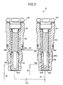
- Fig. 2 is a cross-sectional view of the fuel control device 11 shown in Fig. 1.
- the fuel control device 11 uses two sets of cylinders and pistons and is configured to be capable of performing the control of the fuel pressure on the fuel inlet side of the control valve 9 and the takeout of the fuel to the lubricant line 15.
- numeral 50 indicates a pressure control valve for controlling the fuel pressure on the fuel inlet side of the control valve 9.
- a valve piston 52 is slidably housed in the inside of a cylinder 51, and the valve piston 52 is resiliently biased toward the pressure receiving port 51A of the cylinder 51 by means of a resilient biasing mechanism 53.
- the resilient biasing mechanism 53 is constituted of a coil spring, the resilient biasing mechanism 53 is not limited to the coil spring and may use other known proper member.
- an overflow port 51B which is opened or closed by the valve piston 52 is formed in a side wall portion of the cylinder 51.
- valve piston 52 opens the overflow port 51B in response to the fuel pressure in the inside of the pipe 12 which is connected to the pressure receiving port 51A, the fuel in the pipe 12 is released to the drain pipe 13 by way of the overflow port 51B and hence, an operation to maintain the fuel pressure on the fuel inlet side of the control valve 9 at a predetermined pressure is performed.
- the overflow port 51B which is closed by an outer peripheral surface of the valve piston 52 is released and hence, the fuel from the pipe 12 is released to the drain pipe 13 thus lowering the fuel pressure at the pressure receiving port 51A.
- the overflow port 51B is again closed by the outer peripheral surface of the valve piston 52 and the fuel pressure is elevated.
- the valve piston 52 is positioned in response to the fuel pressure at the pressure receiving port 51A and opens or closes the overflow port 51B so as to maintain the fuel pressure at the pressure receiving port 51A at the predetermined level.
- the valve piston 52 of the pressure control valve 50 is formed of a hollow body which has a rear end (resilient-biasing-mechanism-53 side) thereof opened.
- a communication hole 52B which allows the overflow port 51B to be communicated with a hollow portion 52A of the valve piston 52 when the fuel pressure at the pressure receiving port 51A is substantially zero is formed in the valve piston 52.
- a drain port 51C for eliminating a back pressure of the valve piston 52 is formed in the cylinder 51.
- a drain port 51C and the overflow port 51B are communicated with each other.
- Numeral 60 indicates a fuel takeout valve which can take out the fuel for lubrication from the lubricant line 15.
- a valve piston 62 is slidably housed in the inside of a cylinder 61, and the valve piston 62 is resiliently biased toward the pressure receiving port 61A of the cylinder 61 by means of a resilient biasing mechanism 63.
- the valve piston 62 also has a rear end (resilient-biasing-mechanism-63-side) thereof opened.
- the resilient biasing mechanism 63 is constituted of a coil spring, the resilient biasing mechanism 63 is not limited to the coil spring and may use other known proper member.
- a takeout port 61B for taking out fuel which is opened or closed by the valve piston 62 is formed in a side wall portion of the cylinder 61.
- the fuel in the inside of the pipe 12 which is connected to the pressure receiving port 61A is introduced into the inside of the valve piston 62 by way of an orifice 12A.
- the valve piston 62 is operated in response to the pressure of the introduced fuel and opens the takeout port 61B, a portion of the fuel in the inside of the pipe 12 is supplied to the lubricant line 15 and hence, the fuel is supplied to the lubricant line 15 as a lubricant.
- a drain port 61C which eliminates a back pressure on the valve piston 62 is formed in the cylinder 61, and the drain port 61C is connected with the drain port 51C of the pressure control valve 50 by way of the communication passage 70. Since the drain port 51C is communicated with the drain pipe 13 by way of the communication hole 52B and the port 51B, the pressures on the back surfaces of the valve piston 52 and the valve piston 62 are always set approximately equal to the pressure in the inside of the fuel tank 2 which constitutes a fuel low-pressure portion. As a result, both of valve pistons 52, 62 are configured to be smoothly operated in response to the fuel pressures at the corresponding pressure receiving ports 51A, 61A.
- a resilient force of the resilient biasing mechanism 63 of the fuel takeout valve 60 is set to a small value compared to a resilient force of the resilient biasing mechanism 53 of the pressure control valve 50 and hence, when the pressure of the pressure receiving port 61A reaches the fuel pressure necessary for starting, the takeout port 61B is opened and the fuel is supplied to the lubricant line 15 from the pipe 12 as the lubricant.
- the fuel control device 11 is constituted as described above, while the desired pressure control operation is performed by the pressure control valve 50, the supply of lubricant is performed by the fuel takeout valve 60 independently from the pressure control operation and hence, even when the pressure elevation arises in the lubricant line 15, for example, it is possible to surely perform the desired fuel pressure control operation using the pressure control valve 50 without being influenced by the pressure elevation.
- the fuel control device 11 Since the fuel control device 11 is operated in the above-mentioned manner, even when the pressure elevation arises in the lubricant line 15 due to some reasons, the operation of the valve piston 52 for controlling the fuel pressure at the pressure receiving port 51A is not influenced at all. As a result, it is possible to take out the fuel for lubrication from the pipe 12 without causing troubles in the pressure control operation of the fuel supplied from the low-pressure pump 3 by the pressure control valve 50. That is, even when the back pressure is generated in the lubricant line 15, it is possible to realize a stable flow rate control in the control valve 9 without generating a change in the pressure control characteristic of the fuel pressure on the fuel inlet side of the control valve 9.
- Fig. 3 is a cross-sectional view showing another embodiment of the fuel control device 11 shown in Fig. 1.
- a fuel control valve 110 shown in Fig. 3 includes a pressure control valve 500 and a fuel takeout valve 600.
- the pressure control valve 500 differs from the pressure control valve 50 shown in Fig. 2 only with respect to a point that the drain port 51C is not provided to the pressure control valve 500.
- the fuel takeout valve 600 differs from the fuel takeout valve 60 shown in Fig. 2 only with respect to a point that the communication hole 62B is formed in the valve piston 62 in place of the drain port 61C. Accordingly, the constitution shown in Fig. 3 is not provided with the communication passage 70.
- the parts corresponding to the parts shown in Fig. 2 are given equal numerals and their explanation is omitted.
- the fuel takeout valve 600 is a valve which supplies the lubrication fuel to the cam chamber 102C, even when the back pressure is equal to the pressure inside the pump chamber, provided that the supply pressure is applied to the pressure receiving port 61A so as to open the fuel takeout valve 600, there arises no functional problems. In other words, at least there is no possibility that the back pressure of pressure control valve 500 is influenced by the pressure of the pump chamber.
- the fuel supply device can take out the fuel for lubrication without causing troubles in the pressure control operation of the supplied fuel thus contributing to the enhancement of the fuel supply device.
Landscapes
- Engineering & Computer Science (AREA)
- General Engineering & Computer Science (AREA)
- Mechanical Engineering (AREA)
- Chemical & Material Sciences (AREA)
- Combustion & Propulsion (AREA)
- Fuel-Injection Apparatus (AREA)
Abstract
A fuel control device (11) which is provided on a fuel outlet side of a low-pressure pump (3) for controlling a fuel supply pressure from the low-pressure pump (3) to a predetermined pressure includes a pressure control valve (50) for controlling a fuel pressure of the fuel outlet side and a fuel takeout valve (60). The fuel takeout valve (60) has a valve opening pressure which is smaller than a valve opening pressure of the pressure control valve (50), a drain port (50C) of the pressure control valve (50) and a drain port (61C) of the fuel takeout vale (60) are connected to a fuel low-pressure side by way of a drain pipe (13), and back pressures of pistons (52), (62) are maintained at a fuel-low-pressure-side pressure of the low-pressure pump (3).
Description
- The present invention relates to a fuel supply device for supplying fuel to an internal combustion engine.
- As a fuel supply device for supplying fuel to an internal combustion engine, recently, a common rail-type fuel supply device has been practically used. The common rail-type fuel supply device is constituted as follows. The fuel in the inside of a fuel tank is pumped up by a low-pressure fuel pump such as a feed pump, the fuel is pressurized to a high pressure by a high-pressure fuel pump and is accumulated in the inside of a common rail, and the high-pressurized fuel in the inside of the common rail is injected and supplied to the inside of a cylinder of an internal combustion engine using a fuel injection valve.
- The high-pressure fuel pump which serves for such a purpose has a driving shaft which is driven by the internal combustion engine, and the driving shaft is driven with a large power of the internal combustion engine thus pressurizing the fuel to a high pressure. To ensure a smooth operation of the high-pressure fuel pump, there has been known a fuel supply device having the following constitution. In a low-pressure fuel pump for a common rail system, there is provided a fuel chamber pressure regulating valve which includes a passage which takes the fuel used as a lubricant for operation of a high-pressure-system fuel pump therein. This fuel chamber pressure regulating valve is also allowed to function as a pressure control valve which maintains a proper fuel chamber pressure. Due to such a constitution, at the time of starting the engine, the supply of fuel to a lubricant line is prevented until the pressure which is sufficient for the fuel injection is generated in the fuel chamber thus ensuring the favorable starting property (
JP-A-2002-322968 - However, according to this known fuel supply device, when the pressure of a lubricant line is elevated due to some reasons, a back pressure is applied to a piston of the fuel chamber pressure regulating valve and hence, the movement of the piston is interrupted whereby a fuel pressure control operation is not performed as expected thus giving rise to a drawback that the pressure of the fuel which is supplied to the high-pressure fuel pump becomes excessively large.
- It is an object of the present invention to provide a fuel supply device which can overcome the above-mentioned drawbacks of the related art.
- It is another object of the present invention to provide a fuel supply device which can perform a fuel pressure control operation without troubles even when a back pressure is applied to a lubricant line.
- According to the present invention, there is provided a fuel supply device which includes a pump which supplies a supply fuel under pressure and a fuel pressure control valve which is provided on a fuel outlet side of the pump for controlling a fuel supply pressure from the pump to a predetermined pressure, wherein the fuel supply device further includes a fuel takeout valve which has a valve opening pressure smaller than a valve opening pressure of the fuel pressure control valve for obtaining fuel for lubrication on the fuel outlet side, and a back pressure of a valve piston of at least the fuel pressure control valve is maintained at a fuel-low-pressure-side pressure of the pump.
- According to the present invention, there is also provided a fuel supply device which includes a pump which supplies a supply fuel under pressure and a fuel pressure control valve which is provided on a fuel outlet side of the pump for controlling a fuel supply pressure from the pump to a predetermined pressure, wherein the fuel supply device further includes a fuel takeout valve which has a valve opening pressure smaller than a valve opening pressure of the fuel pressure control valve for obtaining fuel for lubrication on the fuel outlet side, and back pressures of respective valve pistons of the fuel takeout valve and the fuel pressure control valve are maintained at a fuel-low-pressure-side pressure of the pump.
- According to the present invention, it is possible to take out the fuel for lubrication without disturbing a pressure controlling operation of the fuel supplied from the pump.
-
- Fig. 1 is a constitutional view showing an embodiment of a fuel supply device according to the present invention.
- Fig. 2 is a cross-sectional view of a fuel controlling device shown in Fig. 1.
- Fig. 3 is a cross-sectional view which shows another embodiment of the fuel regulating device shown in Fig. 1.
- The present invention is explained more specifically in conjunction with attached drawings.
- Fig. 1 is a constitutional view showing an embodiment of a fuel supply device according to the present invention. In a fuel supply device 1,
numeral 101 indicates a common rail,numeral 102 indicates a high-pressure pump which supplies a high pressure fuel to thecommon rail 101. Fuel F in the inside of a fuel tank 2 is pressurized by a low-pressure pump 3, and the pressurized fuel is supplied to the high-pressure pump 102 as described later. - A
fuel supply passage 5 having a filter 4 is provided between a fuel inlet-side port 3A of the low-pressure pump 3 and the fuel tank 2 and hence, fuel from which dust and the like are removed by the filter 4 passes through thefuel supply passage 5 and is supplied to the low-pressure pump 3. Numeral 6 indicates a manual pump which is used for manually feeding the fuel into the low-pressure pump 3 when air enters a low pressure system line by exchanging a filter or the like. - A fuel supply passage 7 for feeding the low pressure fuel supplied from the low-
pressure pump 3 to a high-pressure pump 102 is provided between anoutlet port 3B on a fuel outlet side of the low-pressure pump 3 and aninlet port 102A of the high-pressure pump 102. Here, in the fuel supply passage 7, a filter 8 for removing dust contained in the fuel which is fed from the low-pressure pump 3 and a control valve 9 for controlling a flow rate of the low-pressure fuel supplied to the high-pressure pump 102 which is constituted using a proportional solenoid valve are provided. The low-pressure fuel whose flow rate is controlled by the control valve 9 is supplied from theinlet port 102A of the high-pressure pump 102 to the inside of acylinder chamber 102B by way of acheck valve 10. The control valve 9 is controlled by a control unit not shown in the drawings, and the flow rate of the low-pressure fuel is controlled so as to allow a rail pressure in the inside of thecommon rail 101 to become a predetermined target rail pressure. - For maintaining the pressure of the low-pressure fuel on the fuel inlet side of the control valve 9 to a predetermined value, a fuel regulating
device 11 is connected to the fuel supply passage 7. In the fuel supply device 1 shown in Fig. 1, to the fuel supply passage 7 between the filter 8 and the control valve 9,pressure receiving ports fuel regulating device 11 are connected by way of apipe 12. The fuel regulatingdevice 11 is configured to be operated such that when the pressure of the low-pressure fuel at thepressure receiving port 51A exceeds a predetermined level, the low-pressure fuel is made to overflow from theoverflow port 51B and hence, the pressure of the low-pressure fuel at the inlet side of the control valve 9 is maintained at an approximately predetermined fixed pressure. The overflow low-pressure fuel from theoverflow port 51B is made to return to the inside of the fuel tank 2 through adrain pipe 13. - The fuel regulating
device 11 further includes atakeout port 61B for taking out the fuel supplied to thepressure receiving port 61A from the low-pressure pump 3 as a lubricant,
wherein the fuel which is taken out from thetakeout port 61B is supplied to the inside of a cam chamber 102C of a high-pressure pump 102 through alubricant line 15 which is provided with on orifice means 14 having a suitable constitution, and the fuel is used as a lubricant for the high-pressure pump 102. Here,numerals - As has been explained above, the low-pressure fuel which is controlled to the predetermined pressure by the fuel supply device 1 has a flow rate thereof controlled and is supplied to the high-
pressure pump 102. Then, the high-pressure fuel which is produced by being pressurized in the inside of thecylinder chamber 102B is supplied to thecommon rail 101 from adischarge port 102D of the high-pressure pump 102 by way of acheck valve 19 and ahigh pressure pipe 20. - Fig. 2 is a cross-sectional view of the
fuel control device 11 shown in Fig. 1. Thefuel control device 11 uses two sets of cylinders and pistons and is configured to be capable of performing the control of the fuel pressure on the fuel inlet side of the control valve 9 and the takeout of the fuel to thelubricant line 15. - In Fig. 2, numeral 50 indicates a pressure control valve for controlling the fuel pressure on the fuel inlet side of the control valve 9. In the pressure control valve 50, a
valve piston 52 is slidably housed in the inside of acylinder 51, and thevalve piston 52 is resiliently biased toward thepressure receiving port 51A of thecylinder 51 by means of aresilient biasing mechanism 53. Here, although theresilient biasing mechanism 53 is constituted of a coil spring, theresilient biasing mechanism 53 is not limited to the coil spring and may use other known proper member. In a side wall portion of thecylinder 51, anoverflow port 51B which is opened or closed by thevalve piston 52 is formed. When thevalve piston 52 opens theoverflow port 51B in response to the fuel pressure in the inside of thepipe 12 which is connected to thepressure receiving port 51A, the fuel in thepipe 12 is released to thedrain pipe 13 by way of theoverflow port 51B and hence, an operation to maintain the fuel pressure on the fuel inlet side of the control valve 9 at a predetermined pressure is performed. - That is, when the fuel pressure at the
pressure receiving port 51A exceeds a predetermined value, theoverflow port 51B which is closed by an outer peripheral surface of thevalve piston 52 is released and hence, the fuel from thepipe 12 is released to thedrain pipe 13 thus lowering the fuel pressure at thepressure receiving port 51A. When the fuel pressure at thepressure receiving port 51A is lowered in this manner, theoverflow port 51B is again closed by the outer peripheral surface of thevalve piston 52 and the fuel pressure is elevated. In this manner, thevalve piston 52 is positioned in response to the fuel pressure at thepressure receiving port 51A and opens or closes theoverflow port 51B so as to maintain the fuel pressure at thepressure receiving port 51A at the predetermined level. - The
valve piston 52 of the pressure control valve 50 is formed of a hollow body which has a rear end (resilient-biasing-mechanism-53 side) thereof opened. Acommunication hole 52B which allows theoverflow port 51B to be communicated with ahollow portion 52A of thevalve piston 52 when the fuel pressure at thepressure receiving port 51A is substantially zero is formed in thevalve piston 52. - On the other hand, a
drain port 51C for eliminating a back pressure of thevalve piston 52 is formed in thecylinder 51. When theoverflow port 51B is communicated with thehollow portion 52A by way of thecommunication hole 52B, adrain port 51C and theoverflow port 51B are communicated with each other. - Numeral 60 indicates a fuel takeout valve which can take out the fuel for lubrication from the
lubricant line 15. In thefuel takeout valve 60, avalve piston 62 is slidably housed in the inside of acylinder 61, and thevalve piston 62 is resiliently biased toward thepressure receiving port 61A of thecylinder 61 by means of aresilient biasing mechanism 63. Thevalve piston 62 also has a rear end (resilient-biasing-mechanism-63-side) thereof opened. Here, although theresilient biasing mechanism 63 is constituted of a coil spring, theresilient biasing mechanism 63 is not limited to the coil spring and may use other known proper member. In a side wall portion of thecylinder 61, atakeout port 61B for taking out fuel which is opened or closed by thevalve piston 62 is formed. The fuel in the inside of thepipe 12 which is connected to thepressure receiving port 61A is introduced into the inside of thevalve piston 62 by way of anorifice 12A. When thevalve piston 62 is operated in response to the pressure of the introduced fuel and opens thetakeout port 61B, a portion of the fuel in the inside of thepipe 12 is supplied to thelubricant line 15 and hence, the fuel is supplied to thelubricant line 15 as a lubricant. - A
drain port 61C which eliminates a back pressure on thevalve piston 62 is formed in thecylinder 61, and thedrain port 61C is connected with thedrain port 51C of the pressure control valve 50 by way of thecommunication passage 70. Since thedrain port 51C is communicated with thedrain pipe 13 by way of thecommunication hole 52B and theport 51B, the pressures on the back surfaces of thevalve piston 52 and thevalve piston 62 are always set approximately equal to the pressure in the inside of the fuel tank 2 which constitutes a fuel low-pressure portion. As a result, both ofvalve pistons pressure receiving ports - A resilient force of the
resilient biasing mechanism 63 of thefuel takeout valve 60 is set to a small value compared to a resilient force of theresilient biasing mechanism 53 of the pressure control valve 50 and hence, when the pressure of thepressure receiving port 61A reaches the fuel pressure necessary for starting, thetakeout port 61B is opened and the fuel is supplied to thelubricant line 15 from thepipe 12 as the lubricant. - Since the
fuel control device 11 is constituted as described above, while the desired pressure control operation is performed by the pressure control valve 50, the supply of lubricant is performed by thefuel takeout valve 60 independently from the pressure control operation and hence, even when the pressure elevation arises in thelubricant line 15, for example, it is possible to surely perform the desired fuel pressure control operation using the pressure control valve 50 without being influenced by the pressure elevation. - Since the
fuel control device 11 is operated in the above-mentioned manner, even when the pressure elevation arises in thelubricant line 15 due to some reasons, the operation of thevalve piston 52 for controlling the fuel pressure at thepressure receiving port 51A is not influenced at all. As a result, it is possible to take out the fuel for lubrication from thepipe 12 without causing troubles in the pressure control operation of the fuel supplied from the low-pressure pump 3 by the pressure control valve 50. That is, even when the back pressure is generated in thelubricant line 15, it is possible to realize a stable flow rate control in the control valve 9 without generating a change in the pressure control characteristic of the fuel pressure on the fuel inlet side of the control valve 9. - Fig. 3 is a cross-sectional view showing another embodiment of the
fuel control device 11 shown in Fig. 1. Afuel control valve 110 shown in Fig. 3 includes apressure control valve 500 and afuel takeout valve 600. Thepressure control valve 500 differs from the pressure control valve 50 shown in Fig. 2 only with respect to a point that thedrain port 51C is not provided to thepressure control valve 500. On the other hand, thefuel takeout valve 600 differs from thefuel takeout valve 60 shown in Fig. 2 only with respect to a point that thecommunication hole 62B is formed in thevalve piston 62 in place of thedrain port 61C. Accordingly, the constitution shown in Fig. 3 is not provided with thecommunication passage 70. Here, with respect to respective parts in Fig. 3, the parts corresponding to the parts shown in Fig. 2 are given equal numerals and their explanation is omitted. - According to the constitution shown in Fig. 3, only the
communication hole 52B formed in thevalve piston 52 of thepressure control valve 500 is connected with thedrain pipe 13 and hence, the back pressure of thepressure control valve 500 is maintained at the fuel-low-pressure-side pressure. On the other hand, the back pressure of thefuel takeout valve 600 is released to a cam chamber 102C of the high-pressure pump 102 by way of thecommunication hole 62B and hence, the back pressure becomes equal to the pump chamber pressure of the high-pressure pump 102. Since thefuel takeout valve 600 is a valve which supplies the lubrication fuel to the cam chamber 102C, even when the back pressure is equal to the pressure inside the pump chamber, provided that the supply pressure is applied to thepressure receiving port 61A so as to open thefuel takeout valve 600, there arises no functional problems. In other words, at least there is no possibility that the back pressure ofpressure control valve 500 is influenced by the pressure of the pump chamber. - As has been explained heretofore, the fuel supply device according to the present invention can take out the fuel for lubrication without causing troubles in the pressure control operation of the supplied fuel thus contributing to the enhancement of the fuel supply device.
Claims (9)
- A fuel supply device comprising a pump which supplies a supply fuel under pressure and a fuel pressure control valve which is provided on a fuel outlet side of the pump for controlling a fuel supply pressure from the pump to a predetermined pressure, wherein the fuel supply device further includes a fuel takeout valve which has a valve opening pressure smaller than a valve opening pressure of the fuel pressure control valve for obtaining fuel for lubrication on the fuel outlet side, and a back pressure of a valve piston of at least the fuel pressure control valve is maintained at a fuel-low-pressure-side pressure of the pump.
- A fuel supply device according to claim 1, wherein the valve piston of the fuel control valve is configured such that the valve piston is slidably housed in the inside of a cylinder and the valve piston is resiliently biased toward a pressure receiving port of the cylinder by a resilient biasing mechanism, fuel from the pump is supplied to the pressure receiving port, and an overflow port which is formed in the cylinder is closed or opened by the valve piston thus performing a fuel pressure control operation.
- A fuel supply device according to claim 2, wherein the valve piston is formed of a hollow body which has a rear end thereof opened, and through a communication hole which is formed in the valve piston to be communicated with the overflow port, the back pressure of the valve piston is maintained at the fuel-low-pressure-side pressure.
- A fuel supply device according to claim 2, wherein the valve piston of the fuel takeout valve is configured such that the valve piston is slidably housed in the inside of a cylinder and the valve piston is resiliently biased toward a pressure receiving port of the cylinder by a resilient biasing mechanism, fuel from the pump is supplied to the pressure receiving port, and an overflow port which is formed in the cylinder is closed or opened by the valve piston thus obtaining the fuel for lubrication from the overflow port.
- A fuel supply device according to claim 4, wherein a drain port which is formed in the cylinder of the fuel control valve and a drain port which is formed in the cylinder of the fuel takeout valve are connected with each other by way of a communication passage thus maintaining a back pressure of the valve piston of the fuel takeout valve at the fuel-low-pressure-side pressure.
- A fuel supply device comprising a pump which supplies a supply fuel under pressure and a fuel pressure control valve which is provided on a fuel outlet side of the pump for controlling a fuel supply pressure from the pump to a predetermined pressure, wherein the fuel supply device further includes a fuel takeout valve which has a valve opening pressure smaller than a valve opening pressure of the fuel pressure control valve for obtaining fuel for lubrication on the fuel outlet side, and back pressures of respective value pistons of the fuel takeout valve and the fuel control valve are maintained at a fuel-low-pressure-side pressure of the pump.
- A fuel supply device according to claim 6, wherein the valve piston of the fuel control valve is configured such that the valve piston is slidably housed in the inside of a cylinder and the valve piston is resiliently biased toward a pressure receiving port of the cylinder by a resilient biasing mechanism, fuel from the pump is supplied to the pressure receiving port, and an overflow port which is formed in the cylinder is closed or opened by the valve piston thus performing a fuel pressure control operation.
- A fuel supply device according to claim 7, wherein the valve piston is formed of a hollow body which has a rear end thereof opened, and through a communication hole which is formed in the valve piston to be communicated with the overflow port, the back pressure of the valve piston is maintained at the fuel-low-pressure-side pressure.
- A fuel supply device according to claim 7, wherein the valve piston of the fuel takeout valve is configured such that the valve piston is slidably housed in the inside of a cylinder and the valve piston is resiliently biased toward a pressure receiving port of the cylinder by a resilient biasing mechanism, fuel from the pump is supplied to the pressure receiving port, and an overflow port which is formed in the cylinder is closed or opened by the valve piston thus obtaining the fuel for lubrication from the overflow port.
Applications Claiming Priority (2)
| Application Number | Priority Date | Filing Date | Title |
|---|---|---|---|
| JP2003432549A JP2005188432A (en) | 2003-12-26 | 2003-12-26 | Fuel supply device |
| PCT/JP2004/019746 WO2005064147A1 (en) | 2003-12-26 | 2004-12-24 | Fuel supply device |
Publications (2)
| Publication Number | Publication Date |
|---|---|
| EP1707795A1 true EP1707795A1 (en) | 2006-10-04 |
| EP1707795A4 EP1707795A4 (en) | 2007-04-04 |
Family
ID=34736479
Family Applications (1)
| Application Number | Title | Priority Date | Filing Date |
|---|---|---|---|
| EP04808096A Withdrawn EP1707795A4 (en) | 2003-12-26 | 2004-12-24 | Fuel supply device |
Country Status (6)
| Country | Link |
|---|---|
| US (1) | US20070272212A1 (en) |
| EP (1) | EP1707795A4 (en) |
| JP (1) | JP2005188432A (en) |
| KR (1) | KR20060101782A (en) |
| CN (1) | CN1902396A (en) |
| WO (1) | WO2005064147A1 (en) |
Cited By (4)
| Publication number | Priority date | Publication date | Assignee | Title |
|---|---|---|---|---|
| EP2105606A1 (en) * | 2008-03-04 | 2009-09-30 | MAGNETI MARELLI POWERTRAIN S.p.A. | Direct injection assembly of the common-rail type provided with a shut-off valve for controlling the delivery of a high-pressure fuel pump |
| ITMI20082210A1 (en) * | 2008-12-12 | 2010-06-13 | Bosch Gmbh Robert | OVER-PRESSURE VALVE FOR A FUEL SUPPLY SYSTEM AND FUEL SUPPLY SYSTEM INCLUDING SUCH OVERPRESSURE VALVE |
| ITMI20110582A1 (en) * | 2011-04-08 | 2012-10-09 | Bosch Gmbh Robert | PUMPING GROUP FOR FOOD FUEL, PREFERIBLY GASOIL, FROM A CONTAINMENT TANK TO AN INTERNAL COMBUSTION ENGINE |
| ITMI20130066A1 (en) * | 2013-01-18 | 2014-07-19 | Bosch Gmbh Robert | PUMPING GROUP FOR FOOD FUEL, PREFERIBLY GASOIL, FROM A CONTAINMENT TANK TO AN INTERNAL COMBUSTION ENGINE |
Families Citing this family (6)
| Publication number | Priority date | Publication date | Assignee | Title |
|---|---|---|---|---|
| JP2008144651A (en) * | 2006-12-08 | 2008-06-26 | Bosch Corp | Pressure control valve and fuel supply pump |
| US20170045005A9 (en) * | 2008-08-29 | 2017-02-16 | Delphi International Operations Luxembourg, S.A.R.L. | Fuel pressure regulation system |
| US9316187B2 (en) * | 2011-01-18 | 2016-04-19 | Carter Fuel Systems, Llc | Diesel fuel system with advanced priming |
| WO2014002206A1 (en) | 2012-06-27 | 2014-01-03 | トヨタ自動車株式会社 | Vehicle control device |
| CN105673283A (en) * | 2016-01-28 | 2016-06-15 | 山东康达精密机械制造有限公司 | Low-pressure oil cavity pressurizing device for inline distribution type electronic control injection pump |
| CN108266369B (en) * | 2017-01-04 | 2021-03-05 | 罗伯特·博世有限公司 | High pressure pump |
Family Cites Families (23)
| Publication number | Priority date | Publication date | Assignee | Title |
|---|---|---|---|---|
| JPS5134938U (en) * | 1974-09-07 | 1976-03-15 | ||
| JPS61122468U (en) * | 1985-01-18 | 1986-08-01 | ||
| JPS62147774U (en) * | 1986-03-13 | 1987-09-18 | ||
| CH674243A5 (en) * | 1987-07-08 | 1990-05-15 | Dereco Dieselmotoren Forschung | |
| JP3842331B2 (en) * | 1995-05-26 | 2006-11-08 | ローベルト ボツシユ ゲゼルシヤフト ミツト ベシユレンクテル ハフツング | FUEL SUPPLY DEVICE FOR FUEL SUPPLY FOR INTERNAL COMBUSTION ENGINE AND METHOD FOR OPERATING INTERNAL COMBUSTION ENGINE |
| DE19548278B4 (en) * | 1995-12-22 | 2007-09-13 | Robert Bosch Gmbh | Method and device for controlling an internal combustion engine |
| DE19549108A1 (en) * | 1995-12-29 | 1997-07-03 | Bosch Gmbh Robert | High-pressure fuel generation system for a fuel injection system used in internal combustion engines |
| DE19612412B4 (en) * | 1996-03-28 | 2006-07-06 | Siemens Ag | Control for a pressurized fluid supply system, in particular for the high pressure in a fuel injection system |
| DE19618707C2 (en) * | 1996-05-09 | 1998-12-17 | Siemens Ag | Method and device for regulating a fuel volume flow |
| DE19757655C2 (en) * | 1997-12-23 | 2002-09-26 | Siemens Ag | Method and device for monitoring the function of a pressure sensor |
| JPH11325285A (en) * | 1998-05-11 | 1999-11-26 | Hirose Valve Kogyo Kk | Direct acting relief valve |
| DE19846157A1 (en) * | 1998-10-07 | 2000-04-13 | Bosch Gmbh Robert | Pump arrangement for high-pressure fuel generation |
| DE19900562C2 (en) * | 1999-01-09 | 2000-11-16 | Bosch Gmbh Robert | Common rail system |
| JP2000214932A (en) * | 1999-01-27 | 2000-08-04 | Yanmar Diesel Engine Co Ltd | Pressure control valve |
| IT1310754B1 (en) * | 1999-11-30 | 2002-02-22 | Elasis Sistema Ricerca Fiat | VALVE SYSTEM FOR INLET PRESSURE CONTROL OF A LIQUID IN A HIGH PRESSURE PUMP, AND RELATED VALVE |
| US6439199B2 (en) * | 2000-04-20 | 2002-08-27 | Bosch Rexroth Corporation | Pilot operated throttling valve for constant flow pump |
| DE10057786A1 (en) * | 2000-11-22 | 2002-06-06 | Siemens Ag | Injection system for an internal combustion engine and method for regulating and / or venting such an injection system |
| JP2002322968A (en) * | 2001-04-26 | 2002-11-08 | Denso Corp | Fuel supply device |
| DE10153185A1 (en) * | 2001-10-27 | 2003-05-15 | Bosch Gmbh Robert | Fuel injection system with improved delivery control |
| DE10205187A1 (en) * | 2002-02-08 | 2003-08-21 | Bosch Gmbh Robert | Fuel injection device for an internal combustion engine |
| FR2844304B1 (en) * | 2002-09-10 | 2004-12-10 | Airbus France | ACOUSTICALLY RESISTIVE LAYER FOR ACOUSTIC MITIGATION PANEL, PANEL USING SUCH A LAYER |
| US6755625B2 (en) * | 2002-10-07 | 2004-06-29 | Robert H. Breeden | Inlet throttle valve |
| DE10247564A1 (en) * | 2002-10-11 | 2004-04-22 | Robert Bosch Gmbh | Operating common rail fuel injection system for combustion engine involves driving pressure regulating valve if fuel quantity less than threshold so defined leakage occurs at pressure regulating valve |
-
2003
- 2003-12-26 JP JP2003432549A patent/JP2005188432A/en active Pending
-
2004
- 2004-12-24 US US10/584,416 patent/US20070272212A1/en not_active Abandoned
- 2004-12-24 EP EP04808096A patent/EP1707795A4/en not_active Withdrawn
- 2004-12-24 KR KR1020067012742A patent/KR20060101782A/en not_active Ceased
- 2004-12-24 WO PCT/JP2004/019746 patent/WO2005064147A1/en not_active Ceased
- 2004-12-24 CN CNA2004800391495A patent/CN1902396A/en active Pending
Cited By (7)
| Publication number | Priority date | Publication date | Assignee | Title |
|---|---|---|---|---|
| EP2105606A1 (en) * | 2008-03-04 | 2009-09-30 | MAGNETI MARELLI POWERTRAIN S.p.A. | Direct injection assembly of the common-rail type provided with a shut-off valve for controlling the delivery of a high-pressure fuel pump |
| US7900602B2 (en) | 2008-03-04 | 2011-03-08 | MAGNETI MARELLI S.p.A. | Direct injection assembly of the common-rail type provided with a shut-off valve for controlling the delivery of a high-pressure fuel pump |
| ITMI20082210A1 (en) * | 2008-12-12 | 2010-06-13 | Bosch Gmbh Robert | OVER-PRESSURE VALVE FOR A FUEL SUPPLY SYSTEM AND FUEL SUPPLY SYSTEM INCLUDING SUCH OVERPRESSURE VALVE |
| ITMI20110582A1 (en) * | 2011-04-08 | 2012-10-09 | Bosch Gmbh Robert | PUMPING GROUP FOR FOOD FUEL, PREFERIBLY GASOIL, FROM A CONTAINMENT TANK TO AN INTERNAL COMBUSTION ENGINE |
| WO2012136429A1 (en) * | 2011-04-08 | 2012-10-11 | Robert Bosch Gmbh | Pump unit for supplying fuel, preferably diesel oil, from a containing tank to an internal combustion engine |
| CN103477065A (en) * | 2011-04-08 | 2013-12-25 | 罗伯特·博世有限公司 | Pump unit for supplying fuel, preferably diesel, from a fuel storage tank to an internal combustion engine |
| ITMI20130066A1 (en) * | 2013-01-18 | 2014-07-19 | Bosch Gmbh Robert | PUMPING GROUP FOR FOOD FUEL, PREFERIBLY GASOIL, FROM A CONTAINMENT TANK TO AN INTERNAL COMBUSTION ENGINE |
Also Published As
| Publication number | Publication date |
|---|---|
| US20070272212A1 (en) | 2007-11-29 |
| EP1707795A4 (en) | 2007-04-04 |
| CN1902396A (en) | 2007-01-24 |
| KR20060101782A (en) | 2006-09-26 |
| JP2005188432A (en) | 2005-07-14 |
| WO2005064147A1 (en) | 2005-07-14 |
Similar Documents
| Publication | Publication Date | Title |
|---|---|---|
| CN100460667C (en) | fuel supply system | |
| WO2009128176A1 (en) | Fuel supply device | |
| EP1365142B1 (en) | High-pressure fuel pump | |
| CN102333950B (en) | High-pressure pump arrangement | |
| US6510843B2 (en) | Valve system for controlling the fuel intake pressure in a high-pressure pump | |
| CN105888906A (en) | Fuel high-pressure pump for internal combustion engine | |
| EP1111229A2 (en) | Fuel injection valve for reciprocating internal combustion engine | |
| EP2215350B1 (en) | Safety valve and high-pressure pump comprising said safety valve | |
| JPH06323220A (en) | Fuel injection device for internal combustion engine | |
| US20070272212A1 (en) | Fuel Supply Device | |
| CN100467857C (en) | Adjustment device | |
| US7438057B2 (en) | Fuel injection system | |
| CN101235778B (en) | Fuel injection pump | |
| JP4887421B2 (en) | Supply pump for high-pressure gasoline fuel injection | |
| JP2001248527A (en) | Variable discharge fuel supply device | |
| US20180202537A1 (en) | Feed limit valve integrated stopstart accumulator | |
| JP2004278491A (en) | Fuel injecting device for internal combustion engine | |
| US7096856B2 (en) | Fuel feed pump for internal combustion engines | |
| JP2008038689A (en) | Fuel supply device | |
| US10174735B2 (en) | Injection device for an internal combustion engine | |
| TWI917737B (en) | Method of operating a diaphragm pump and pumping system | |
| JP3884665B2 (en) | Accumulated distribution fuel injection pump | |
| KR100739939B1 (en) | Fuel supply | |
| TW202340609A (en) | Diaphragm position control system | |
| JP2006083822A (en) | Intake control valve of supply pump |
Legal Events
| Date | Code | Title | Description |
|---|---|---|---|
| PUAI | Public reference made under article 153(3) epc to a published international application that has entered the european phase |
Free format text: ORIGINAL CODE: 0009012 |
|
| 17P | Request for examination filed |
Effective date: 20060620 |
|
| AK | Designated contracting states |
Kind code of ref document: A1 Designated state(s): DE FR GB |
|
| A4 | Supplementary search report drawn up and despatched |
Effective date: 20070306 |
|
| DAX | Request for extension of the european patent (deleted) | ||
| RBV | Designated contracting states (corrected) |
Designated state(s): DE FR GB |
|
| STAA | Information on the status of an ep patent application or granted ep patent |
Free format text: STATUS: THE APPLICATION HAS BEEN WITHDRAWN |
|
| 18W | Application withdrawn |
Effective date: 20070719 |