EP1707768A1 - Valve operating device for engine - Google Patents
Valve operating device for engine Download PDFInfo
- Publication number
- EP1707768A1 EP1707768A1 EP05703531A EP05703531A EP1707768A1 EP 1707768 A1 EP1707768 A1 EP 1707768A1 EP 05703531 A EP05703531 A EP 05703531A EP 05703531 A EP05703531 A EP 05703531A EP 1707768 A1 EP1707768 A1 EP 1707768A1
- Authority
- EP
- European Patent Office
- Prior art keywords
- rocker arm
- intake
- valve operating
- arm
- shaft
- Prior art date
- Legal status (The legal status is an assumption and is not a legal conclusion. Google has not performed a legal analysis and makes no representation as to the accuracy of the status listed.)
- Withdrawn
Links
Images







Classifications
-
- F—MECHANICAL ENGINEERING; LIGHTING; HEATING; WEAPONS; BLASTING
- F01—MACHINES OR ENGINES IN GENERAL; ENGINE PLANTS IN GENERAL; STEAM ENGINES
- F01L—CYCLICALLY OPERATING VALVES FOR MACHINES OR ENGINES
- F01L13/00—Modifications of valve-gear to facilitate reversing, braking, starting, changing compression ratio, or other specific operations
- F01L13/0015—Modifications of valve-gear to facilitate reversing, braking, starting, changing compression ratio, or other specific operations for optimising engine performances by modifying valve lift according to various working parameters, e.g. rotational speed, load, torque
-
- F—MECHANICAL ENGINEERING; LIGHTING; HEATING; WEAPONS; BLASTING
- F01—MACHINES OR ENGINES IN GENERAL; ENGINE PLANTS IN GENERAL; STEAM ENGINES
- F01L—CYCLICALLY OPERATING VALVES FOR MACHINES OR ENGINES
- F01L1/00—Valve-gear or valve arrangements, e.g. lift-valve gear
- F01L1/12—Transmitting gear between valve drive and valve
- F01L1/18—Rocking arms or levers
- F01L1/185—Overhead end-pivot rocking arms
-
- F—MECHANICAL ENGINEERING; LIGHTING; HEATING; WEAPONS; BLASTING
- F01—MACHINES OR ENGINES IN GENERAL; ENGINE PLANTS IN GENERAL; STEAM ENGINES
- F01L—CYCLICALLY OPERATING VALVES FOR MACHINES OR ENGINES
- F01L13/00—Modifications of valve-gear to facilitate reversing, braking, starting, changing compression ratio, or other specific operations
- F01L13/0015—Modifications of valve-gear to facilitate reversing, braking, starting, changing compression ratio, or other specific operations for optimising engine performances by modifying valve lift according to various working parameters, e.g. rotational speed, load, torque
- F01L13/0021—Modifications of valve-gear to facilitate reversing, braking, starting, changing compression ratio, or other specific operations for optimising engine performances by modifying valve lift according to various working parameters, e.g. rotational speed, load, torque by modification of rocker arm ratio
-
- F—MECHANICAL ENGINEERING; LIGHTING; HEATING; WEAPONS; BLASTING
- F01—MACHINES OR ENGINES IN GENERAL; ENGINE PLANTS IN GENERAL; STEAM ENGINES
- F01L—CYCLICALLY OPERATING VALVES FOR MACHINES OR ENGINES
- F01L1/00—Valve-gear or valve arrangements, e.g. lift-valve gear
- F01L1/26—Valve-gear or valve arrangements, e.g. lift-valve gear characterised by the provision of two or more valves operated simultaneously by same transmitting-gear; peculiar to machines or engines with more than two lift-valves per cylinder
- F01L1/267—Valve-gear or valve arrangements, e.g. lift-valve gear characterised by the provision of two or more valves operated simultaneously by same transmitting-gear; peculiar to machines or engines with more than two lift-valves per cylinder with means for varying the timing or the lift of the valves
-
- F—MECHANICAL ENGINEERING; LIGHTING; HEATING; WEAPONS; BLASTING
- F01—MACHINES OR ENGINES IN GENERAL; ENGINE PLANTS IN GENERAL; STEAM ENGINES
- F01L—CYCLICALLY OPERATING VALVES FOR MACHINES OR ENGINES
- F01L2305/00—Valve arrangements comprising rollers
-
- F—MECHANICAL ENGINEERING; LIGHTING; HEATING; WEAPONS; BLASTING
- F01—MACHINES OR ENGINES IN GENERAL; ENGINE PLANTS IN GENERAL; STEAM ENGINES
- F01L—CYCLICALLY OPERATING VALVES FOR MACHINES OR ENGINES
- F01L2820/00—Details on specific features characterising valve gear arrangements
- F01L2820/03—Auxiliary actuators
- F01L2820/032—Electric motors
Definitions
- the present invention relates to an engine valve operating system equipped with a variable valve lift mechanism which continuously varies the lift amount of an engine valve, namely an intake valve or exhaust valve.
- a valve operating system in which one end of a push rod is fitted to one end of a rocker arm having a valve abutment part abutting to an engine valve at the other end side and a link mechanism is provided between the other end of the push rod and a valve operating cam in order to continuously change the amount of lift of the engine valve is already known by Patent Document 1.
- the valve operating system it is possible to make the valve operating system compact and it is also possible to ensure excellent follow-up ability to the valve operating cam by directly transmitting the power from the valve operating cam to the rocker arm.
- the rocker arm is desirably configured so that a valve connecting portion provided on the rocker arm so as to be connected to the engine valves has a maximum width, in order to minimize the width of the rocker arm. This is because the distance between the engine valves is substantially determined by the shape and dimensions of a combustion chamber and because the width of the valve connecting portion is in turn determined by the distance between the engine valves.
- the present invention has been achieved in view of the above-mentioned circumstances, and has an object to provide an engine valve operating system which allows the lift amount of an engine valve to be continuously varied and which has a reduced size, while ensuring follow-up ability of the opening/closing operations.
- an engine valve operating system comprising a rocker arm which has a cam abutting portion abutting against a valve operating cam and which is interlocked and connected to an engine valve, a first link arm having one end turnably connected to the rocker arm and the other end turnably supported at a fixed position of the engine body, a second link arm having one end turnably connected to the rocker arm and the other end turnably supported by a displaceable movable support shaft, and driving means connected to the movable support shaft to enable a position of the movable support shaft to be displaced in order to continuously vary the lift amount of the engine valve, wherein the rocker arm having a valve connecting portion into which tappet screws abutting against a pair of engine valves are screwed so that their advance/retract positions can be adjusted and a first and second support portions to which the one ends of the first and second link arms are turnably connected is formed so that the valve connecting portion has a larger width
- the other end of the first link arm is turnably supported via a support shaft by support walls provided in the engine body so as to lie on opposite sides of the other end of the first link arm.
- An interposition is placed between the other end of the first link arm and each of the support walls.
- the interposition is a torsion spring provided between the engine body and the rocker arm so as to bias the rocker arm in a side in which the cam abutting portion abuts against the valve operating cam.
- the first support portion is formed into a substantial U shape so as to sandwich a roller which is the cam abutting portion, between the opposite sides, and the roller is rotatably supported by the first support portion.
- a pair of connecting portions is provided at the one end of the first link arm so as to sandwich the first support portion of the rocker arm between the connecting portions.
- the connecting portions are turnably connected to the first support portion via a connecting shaft.
- the roller is axially supported by the first support portion via the connecting shaft.
- the rocker arm is formed so that the first and second support portions have the same width.
- connecting holes throughwhich connecting shafts used to turnably connect the one ends of the first and second link arms are inserted are formed in the first and second support positions so as to be side by side in a direction of opening/closing directions of the engine valves.
- the first and second support portions are connected together by a connecting wall at least partly placed opposite from the engine valves with respect to a tangent contacting with outer edges of the connecting holes near the engine valves.
- a concave portion is formed in the connecting wall at a position opposite from the other end of the second link arm when the other end of the second link arm is closest to the rocker arm.
- a lightening portion is formed in the connecting wall.
- lightening portions are alternately formed in opposite surfaces of the rocker arm molded.
- the lift amount of the engine valve can be continuously varied by continuously displacing the movable support shaft. Further, since one ends of each of the first and second link arms are turnably connected directly to the rocker arm. This allows a reduction in the size of the space in which the link arms are arranged, and in the size of the valve operating system. Furthermore, power from the valve operating cam is transmitted directly to the cam abutting portion of the rocker arm. This ensures excellent follow-up ability of the rocker arm to the valve operating cam. Moreover, the rocker arm drivingly opens the pair of engine valves.
- the rocker arm has the valve connecting portion into which the tappet screws abutting against a pair of engine valves are screwed so that their advance/retract positions can be adjusted, and the first and second support portions to which the one ends of the first and second link arms are turnably connected.
- the rocker arm is formed so that the width of the valve connecting portion in the direction along the turning axis of the valve operating cam is larger than that of the remaining part. It is thus possible to minimize the width of the rocker arm in the direction along the turning axis of the valve operating cam. This also enables a reduction in the size of the valve operating system.
- the interposition is placed between the other end of the first link arm and each of the support walls provided in the engine body so as to lie on the opposite sides of the other end of the first link arm.
- a torsion spring which biases the rocker arm in the direction in which the cam abutting portion abuts against the valve operating cam serves as the interposition. This facilitates the absorption of the dimensional tolerance. It is also possible to ensure that the cam abutting portion abuts against the valve operating cam. This increases the accuracy with which the valve lift amount is controlled.
- the first support portion formed into a substantially U-shape rotatably supports the roller. This enables a reduction in the size of the whole rocker arm including the roller.
- the common connecting shaft is used to turnably connect the one end of the first link arm to the first support portion and to allow the first support portion to axially support the roller. This enables a reduction in the number of parts required and thus a further reduction in the size of the valve operating system.
- the first and second support portions have the same width. This makes it possible to reduce the size of the rocker arm, while simplifying its shape.
- the first and second support portions of the rocker arm are connected together by the connecting wall at least partly placed opposite from the engine valves with respect to the tangent contacting with the outer edges of the pair of connecting holes near the engine valve formed in the support portions. This serves to enhance the rigidity of the first and second support portions.
- the other end of the second link arm can be displaced as close to the rocker arm as possible. This enables the maximum lift amount of the engine valves to be set at as large a value as possible, while allowing a reduction in the size of the valve operating system.
- the lightening portions are alternately formed in opposite surfaces of the rocker arm. This makes it possible to reduce the weight of the rocker arm.
- the lightening portions are formed when the rocker arm is molded, and the adjacent lightening portions have draft angles in opposite directions. Accordingly, inner surfaces of the adjacent lightening portions are inclined in the same direction. Therefore, the wall portions formed in the rocker arm between the adjacent lightening portions have substantially an equal uniform in thickness. The wall portions with the substantially equal thickness allow the rigidity of the rocker arm to be maintained.
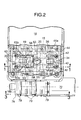
- FIG. 1 is a partial vertical sectional view of an engine according to a first embodiment of the present invention, taken along line 1-1 in FIG. 2. (Embodiment 1)
- FIGS. 1 to 11 show a first embodiment of the present invention.
- an engine body 10 of an in-line multi-cylinder engine E comprises a cylinder block 12 with cylinder bores 11 in the interior, a cylinder head 14 joined to a top face of the cylinder block 12, and a head cover 16 joined to a top face of the cylinder head 14.
- Pistons 13 are slidably fitted in the cylinder bores 11.
- Combustion chambers 15 facing tops of the pistons 13 are formed between the cylinder block 12 and cylinder head 14.
- the cylinder head 14 is equipped with intake ports 17 and exhaust ports 18 which can communicate with combustion chambers 15.
- the intake ports 17 are opened and closed by a pair of intake valves 19, 19 which are engine valves while the exhaust ports 18 are opened and closed by a pair of exhaust valves 20, 20.
- Each intake valve 19 has a stem 19a slidably fitted in a valve guide 21 provided in the cylinder head 14, and is biased in a valve closing direction by a valve spring 24 installed between a spring seat 22 provided at the upper end of the stem 19a and a spring seat 23 abutted by the cylinder head 14.
- Each exhaust valve 20 has a stem 20a slidably fitted in a valve guide 25 provided in the cylinder head 14 and is biased in a valve closing direction by a valve spring 28 installed between a spring seat 26 provided at the upper end of the stem 20a and a spring seat 27 abutted by the cylinder head 14.
- the cylinder head 14 integrally comprises a holder 44 which has supporting walls 44a placed on opposite sides of each cylinder. Caps 45 and 47 are coupled to each supporting wall 44a to form an intake cam holder 46 and exhaust cam holder 48 in conjunction. Consequently, an intake camshaft 31 is rotatably supported by the intake cam holders 46 while an exhaust camshaft 32 is rotatably supported by the exhaust cam holders 48.
- the intake valves 19 are driven by the intake camshaft 31 via variable lifting mechanism 33.
- the exhaust valves 20 are driven by the exhaust camshaft 32 via variable valve timing/lifting means 34.
- variable timing/lifting means 34 which drives the exhaust valves 20 is well-known, and will only be outlined here.
- a pair of low-speed rocker arms 36, 36 and one high-speed rocker arm 37 are pivotably supported at their first ends on an exhaust rocker arm shaft 35 supported by holding walls 44a of exhaust cam holders 48.
- Two low speed cams 39, 39 provided on the exhaust camshaft 32 abut against rollers 38, 38 axially supported in intermediate parts of the low-speed rocker arms 36, 36.
- a high speed cam 41 provided on the exhaust camshaft 32 abuts against a roller 40 axially supported in an intermediate part of the high-speed rocker arm 37.
- Tappet screws 42 which abut against the upper ends of the stems 20a of the exhaust valves 20 are screwed into the second ends of the low speed rocker arms 36 in such a way as to allow their advance/retract position to be adjusted.
- the low speed rocker arms 36, 36 and the high speed rocker arm 37 can be connected and disconnected by hydraulic control.
- the low speed rocker arms 36, 36 and the high speed rocker arm 37 are disconnected, the low speed rocker arms 36, 36 are driven by the corresponding low speed cams 39, 39. Consequently, the exhaust valves 20, 20 are opened and closed with a low valve lift and a low opening angle.
- the high speed rocker arm 37 is driven by the corresponding high speed cam 41.
- the exhaust valves 20, 20 are opened and closed with a high valve lift and a high opening angle by the low speed rocker arms 36, 36 coupled to the high speed rocker arm 37.
- the valve lift and valve timing of the exhaust valves 20, 20 are controlled at two levels by the variable timing/lifting means 34.
- the variable lifting mechanism 33 comprises an intake rocker arm 63 having a roller 65 serving as a cam abutting portion which abuts against an intake valve operating cam 69 provided on the intake cam shaft 31, a first link arm 61 having a first end turnably connected to the intake rocker arm 63 and a second end turnably supported at a fixed position of the engine body 10, and a second link arm 62 having a first end turnably connected to the intake rocker arm 63 and a second end turnably used by a displaceable movable support shaft 68a.
- the intake rocker arm 63 is provided at its first end with a valve connecting portion 63a into which tappet screws 70, 70 are screwed in such a way as to allow advance/retract positions of the screws to be adjusted; the tappet screws 70, 70 abut against the upper ends of the stems 19a of the pair of intake valves 19 from above.
- the second end of the intake rocker arm 63 is formed into a general U shape, opening in opposition to the intake valves 19.
- the second end of the intake rocker arm 63 is provided with a first support portion 63b to which a first end of the first link arm 61 is turnably connected and a second support portion 63c to which a first end of the second link arm 61 is turnably connected; the second support portion 63c is placed below the first support portion 63b.
- a roller 65 is placed so as to be sandwiched between linear portions of a generally U-shaped first support portion 63b; the roller 65 serves as a cam-abutting portion placed in rolling contact with the intake valve operating cam 69 of the intake cam shaft 31.
- the roller 65 is axially supported by the first support portion 63b coaxially with a first end connecting portion of the first link arm 61.
- the intake rocker arm 63 is formed so that the valve connecting portion 63a have a width larger than that of the remaining part in a direction along a turning axis of the intake valve operating cam 69.
- the first and second support portions 63b and 63v are formed to have the same width.
- the first link arm 61 is formed into a substantial U shape with a pair of first connecting portions 61a, 61a which sandwiches the intake rocker arm 63 between them, a cylindrical fixed support portion 61b, and a pair of arm portions 61c which link the first connecting portions 61a, 61a and the fixed support portion 61b.
- the first connecting portions 61a, 61a at the first end of the first link arm 61 are turnably connected to the first support portion 63b of the intake rocker arm 63 via a cylindrical first connecting shaft 64 fixedly inserted into a first connecting hole 49 formed in the first support portion 63b of the intake rocker arm 63.
- the roller 65 is also axially supported by the first support portion 63b via a needle bearing 60 and the first connecting shaft 64. Further, an outer flank of that part of the first support portion 63b which is opposite the intake cam shaft 31 overlaps with outer flanks of the first connecting portions 61a, 61a of the first link arm 61, as viewed laterally; an arc shape is thus formed around the axis of the first connecting shaft 64.
- the second link arm 62 is placed below the first link arm 61.
- the second link arm 62 has a first connecting portion 62a at its first end and a movable support portion 62b at its second end.
- a second connecting portion 62a is placed so as to be sandwiched between linear portions of the generally U-shaped second support portion 63b.
- a second support portion 63c is provided not only with the first connecting hole 49 of the first support portion 63b but also with a second connecting hole 50 located by the side of the first connecting hole 49 in a direction in which both intake valves 19 are opened and closed, that is, in the vertical direction.
- the second connecting portion 62a is turnably connected to the second support portion 63c via a second connecting shaft 66 fixedly inserted into the second connecting hole 50.
- the first end of the intake rocker arm 63 having the roller 65 above the second end abutting against the intake valve operating cam 69 is interlocked with and connected to the pair of intake valves 19.
- the first connecting portions 61a, 61a provided at the first end of the upper first link arm 61 and the second connecting portion 62a provided at the first end of the second link arm 62, located below the first link arm 61, are vertically arranged in parallel and relatively turnably connected to the second arm of the intake rocker arm 63.
- the intake rocker arm 63 is provided integrally with a pair of connect ing walls 63d that links the generally U-shaped first and second support portions 63b and 63c together.
- the connecting walls 63d are formed so as to connect the first and second support portions 63b and 63c together; the connecting walls 63d are at least partly arranged opposite the intake valves 19 with respect to a tangent L which contacts with outer edges of the first and second connecting holes 49 and 50 on the side of both intake valves 19.
- Concave portions 51 are formed in the connecting walls 63d so as to lie opposite the movable support shaft 68a when the movable support portion 62b at the second end of the second link arm 62 is closest to the intake rocker arm 63.
- lightening portions 52 are formed in the connecting walls 63d so as to be recessed from an outer surface to inner surface of each wall.
- a fixed support portion 61b at the second end of the first link arm 61 is turnably supported, via the fixed support shaft 67, by the support walls 44a arranged on the opposite sides of the fixed support portion 61b so as to constitute a lower part of the intake cam holder 46 provided in the engine body 10.
- the fixed support shaft 67 is fixedly supported by the opposite support walls 44a.
- a pair of support bosses 53, 53 stick out integrally from the support walls 44a so as to project toward the fixed support portion 61b of the first link arm 61 in an axial direction.
- Each of the support bosses 53 is provided with a smaller-diameter shaft portion 53a which can slidably contact with the opposite end faces of the fixed support portion 61b and a step portion 53b located opposite and away from the opposite end faces of the fixed support portion 61b so as to surround a proximal end of the smaller-diameter shaft portion 53a.
- the fixed support shaft 67 is fixedly supported by the support bosses 53 so as to coaxially penetrate the smaller-diameter shaft portions 53a.
- Both intake valves 19 are biased by the valve springs 24 in the valve closing direction. While the intake rocker arm 63 is driving, in the valve opening direction, both intake valves 19 biased in the valve closing direction, the valve springs 24 cause the roller 65 of the intake rocker arm 63 to abut against the intake valve operating cam 69. However, while the intake valves 19 are closed, the spring force of the valve springs 24 does not act on the intake rocker arm 63. Consequently, the roller 65 may leave the intake valve operating cam 69 to reduce the accuracy with which the valve lift amount is controlled when the intake valves 19 are to be slightly opened.
- a torsion spring 54 is provided separately from the valve spring 24; the torsion spring 54 is an interposition placed between each of the opposite surfaces of the fixed support portion 61b at the second end of the first link arm 61 and the support boss 53 sticking out from each of the support walls 44a arranged on the opposite sides of the fixed support portion 61b.
- the torsion spring 54 biases the intake rocker arm 63 in a direction in which the roller 65 abuts against the intake valve operating cam 69.
- the torsion spring 54 is placed so as to surround the fixed support shaft 67 via the smaller-diameter shaft portion 53a of the support boss 53.
- the torsion spring 54 is provided between the engine body 10 and the intake rocker arm 63.
- a first end of the torsion spring 54 surrounding the smaller-diameter shaft portion 53a is engaged with the locking pin 55 installed on the step portion 53b of the support boss 53.
- a second end of the torsion spring 54 is inserted into and engaged with the hollow first connecting shaft 64 operating integrally with the intake rocker arm 63.
- the fixed support portion 61b at the second end of the first link arm 61 is formed like a cylinder so that its outer periphery is placed inward of an outer periphery of each torsion spring 54 as viewed laterally, the rocker arm biasing spring being wound like a coil.
- a plurality of, for example, paired projecting portions 56 and 57 are provided away from each other in a circumferential direction so as to stick out from the opposite ends of the fixed support portion 61b in its axial direction.
- the projecting portions 56 and 57 serve to inhibit the torsion springs 54 from being laid down toward the fixed support portion 61b.
- the projecting portions 56 and 57 are arranged outside the operating range of the second link arm 62.
- Oil jets 58 are fixedly placed in the engine body 10 as oil supply means to supply oil to the upper one of the first and second connecting shafts 64 and 66 arranged at the second end of the intake rocker arm 63 vertically in parallel so as to connect the first connecting portions 61a and second connecting portion 62a together, which are provided at the first ends of the first and second link arm 61 and 62.
- the oil jets 58 are fixedly attached to caps 45 of the intake cam holders 46, provided in the engine body 10, to supply oil to the first connecting shaft 64, one of the first and second connecting shafts 64 and 66.
- first support portion 63b is provided in the upper part of the second end of the intake rocker arm 63; the first support portion 63b is formed like a general U shape so as to sandwich the roller 65 between its linear portions.
- the first connecting portions 61a of the first link arm 61 are turnably connected to the first support portion 63b via the first connecting shaft 64, which axially supports the roller 65.
- the oil jets 58 are disposed in the caps 45 so as to supply oil to mating surfaces of the first connecting portions 61a of the first link arm 61 and the first support portion 63b.
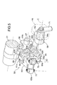
- a crank member 68 is provided with the movable support shaft 68a turnably supporting the movable support portion 62b provided at the second end of the second link arm 62.
- the crank member 68 is provided at the opposite ends of a connecting plate 68b placed on a plane parallel to a plane in which the second link arm 62 operates and at right angles so that the movable support shaft 68a and the support shaft 68c stick out in opposite directions.
- the support shaft 68c is rotatably supported in a support hole 16a formed in the head cover 16 in the engine body 10.
- a control arm 71 is fixed to the tip of the spindle 68c and driven by an actuator motor 72 mounted on an outer wall of the cylinder head 14 and serving as drive means. That is, a nut member 74 meshes with a threaded shaft 73 rotated by the actuator motor 72.
- a first end of a connecting link 76 is pivotably supported on the nut member 74 via a pin 75. The second end is connected to the control arm 71 via pins 77, 77. Therefore, when the actuator motor 72 is operated, the nut member 74 moves along the rotating threaded shaft 73.
- crank member 68 is caused to swing around the spindle 68c by the control arm 71 connected to the nut member 74 via the connecting link 76. Consequently, the movable support shaft 68a moves between the position shown in FIG. 8A and the position shown in FIG. 8B.
- a rotational angle sensor 80 such as a rotary encoder is installed on an outer wall surface of the head cover 16.
- a first end of a sensor arm 81 is fixed to the tip of a sensor shaft 80a of the rotational angle sensor 80.
- a guide groove 82 is provided in the control arm 71 linearly extending along its length.
- a connecting shaft 83 mounted on a second end of the sensor arm 81 is slidably fitted in the guide groove 82.
- the threaded shaft 73, nut member 74, pin 75, connecting link 76, pins 77, 77, control arm 71, rotational angle sensor 80, sensor arm 81, and connecting shaft 83 are housed within wall portions 14a and 16b sticking out from flanks of the cylinder block 14 and head cover 16.
- a cover 78 which covers end faces of the wall portions 14a and 16b is fixed to the wall portions 14a and 16b with bolts 79.
- variable lifting mechanism 33 when the control arm 71 is turned counterclockwise by the actuator motor 72 from the position indicated by the solid line in FIG. 3, the crank member 68 (see FIG. 5) connected to the control arm 71 turns counterclockwise.
- the movable support shaft 68a of the crank member 68 then ascends as shown in FIG. 8A.
- the intake valve operating cam 69 mounted on the intake camshaft 31 pushes the roller 65 in this state, a four-bar link joining the fixed support shaft 67, first connecting shaft 64, second connecting shaft 68, and movable support shaft 68a deforms. This causes the intake rocker arm 63 to swing downward from the chain-line position to the solid-line position.
- the tappet screws 70, 70 then push the stems 19a of the intake valves 19.
- the intake valves 19 are thus opened with a high valve lift.
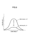
- FIG. 9 is a diagram showing a lift curve of the intake valve 19.
- the opening angle with the high lift corresponding to FIG. 8A is the same as that with the low lift corresponding to FIG. 8B, and only the amount of lift has changed. In this way, the variable lifting mechanism 33 allows only the lift amount to be changed freely without changing the opening angle of the intake valves 19.
- the rotational angle sensor 80 detects the rotational angle of the spindle 68c of the crank member 68. To simply detect the rotational angle of the spindle 68c of the crank member 68, the rotational angle sensor 80 can be connected directly to the spindle 68c.
- the position of the control arm 71 indicated by the solid line in FIG. 10 corresponds to the low lift region.
- the position of the control arm 71 indicated by the chain line in the anticlockwise direction away from the low lift region corresponds to the high lift region.
- the connecting shaft 83 of the sensor arm 81 fixed to the sensor shaft 80a of the rotational angle sensor 80 is engaged with the tip side (the side farther from the axis C) of the guide groove 82 of the control arm 71, even a slight swing of the control arm 71 results in a large swing of the sensor arm 81.
- the resolution of the rotational angle sensor 80 is thus enhanced to enable the rotational angle of the crank member 68 with high accuracy.
- one end (the end closer to the spindle 68c) of the control arm 71 and one end (the end closer to the rotational angle sensor 80) of the sensor arm 81 are placed in proximity to each other.
- the guide groove 82 is formed at the end of the control arm 71. Accordingly, the sensor arm 81 can be made compact with its length reduced. Further, the formation of the guide groove 82 at the end of the control arm 71 reduces the distance from the axis C as well as the amount of travel in the circumferential direction of the guide groove 82. However, the length of the sensor arm 81 is also reduced to allow the sensor arm 81 to turn through a sufficient angle. This ensures the accuracy with which the rotational angle of the sensor 80 is detected.
- variable lifting mechanism 33 which continuously varies the lift amounts of the intake valves 19, the first connection portions 61a, 61a and second connecting portion 62a, attached to the first ends of the first link arm 61 and second link arm 62, respectively, are arranged in parallel and relatively turnably connected to the second end of the intake rocker arm 63 which has a valve connecting portion 63a interlocked and coupled to the pair of intake valves 19 at the first end.
- the fixed support portion 61b at the second end of the first link arm 61 is turnably supported by the fixed support shaft 67 of the engine body 10.
- the movable support portion 62b at the second end of the second link arm 62 is turnably supported by the displaceable movable support shaft 68a.
- the movable support shaft 68a By varying the movable support shaft 68a continuously, it is possible to vary the lift amounts of the intake valves 19 continuously. Moreover, since the first ends of the first and second link arms 61 and 62 are turnably connected directly to the intake rocker arm 63, it is possible to reduce the size of the space in which the link arms 61 and 62 are arranged. This makes it possible to reduce the size of the valve operating system. Further, since power is transmitted directly from the intake valve operating cam 69 to the roller 65 of the intake rocker arm 63, it is possible to follow the intake valve operating cam 69 properly. Furthermore, the intake rocker arm 63 and the first and second link arms 61 and 62 can be placed at almost the same location along the axis of the intake camshaft 31. This enables the size of the valve operating system to be reduced in a direction along the axis of the intake cam shaft 31.
- the valve connecting portion 63a has a width larger than that of the remaining part in a direction along the turning axis of the intake valve operation cam 69.
- the width of the intake rocker arm 63 can thus be reduced in the direction along the turning axis of the intake valve operating cam 69. This also makes it possible to reduce the size of the valve operating system.
- the intake rocker arm 63 is formed so that the first and second support portions 63b and 63c have the same width. It is thus possible to make the intake rocker arm 63 compact in size, while simplifying the shape of this component.
- first support portion 63b provided on the intake rocker arm 63, is formed into a substantial U shape so as to sandwich the roller 65 between its linear portions.
- the roller 65 is rotatably supported by the first support portion 63b. Accordingly, the whole intake rocker arm 63, including the roller 65, can be made compact in size.
- the paired first connecting portions 61a sandwiching the first support portions 63b between them are provided at the first end of the first link arm 61. Both first connecting portions 61a are turnably connected to the first support portion 63b via the first connecting shaft 64.
- the roller 65 is supported by the first support portion 63b via the first connecting shaft 64.
- the common first connecting shaft 64 is used to turnably connect the first end of the first link arm 61 to the first support portion 63b and to allow the first support portion 63b to support the roller 65. This makes it possible to reduce the number of parts required and the size of the valve operating system.
- the first and second connecting holes 49 and 50 are formed in the first and second support portions 63b and 63c of the intake rocker arm 63 so as to lie side by side in the direction in which the intake valves 19 are opened and closed; the first and second connecting shafts 64 and 66 to which the first ends of the first and second link arms 61 and 62 are turnably connected are inserted into the first and second connecting holes 49 and 50.
- the first and second support portions 63b and 63c are connected together by the connecting walls 63d at least partly arranged opposite both intake valves 19 with respect to the tangent L which contacts with the outer edges of the first and second connecting holes 49 and 50 on the side of both intake valves 19. This serves to enhance the rigidity of the first and second support portions 63b and 63c.
- the concave portions 51 are formed in the connecting walls 63d so as to sit opposite the second connecting position 62a when the second connecting portion 62a at the second end of the second link arm 62 is closest to the intake rocker arm 63. Accordingly, the second connecting portion 62a of the second link arm 62 can be displaced to a position where it is as close to the intake rocker arm 63 as possible. This makes it possible to set the maximum lift amount of the intake valve 19 at as large a value as possible while reducing the size of the valve operating system.
- the lightening portions 52 are formed in the connecting walls 63d. This suppresses an increase in the weight of the intake rocker arm 63, while allowing the rigidity to be enhanced using the connecting walls 63d.
- the oil jets 58 are fixedly arranged in the engine body 10 to supply oil to the first connecting shaft 64, the upper one of the first and second connecting shafts 64 and 66, which connect the first ends of the first and second link arms 61 and 62 to the intake rocker arm 63.
- the first support portion 63b formed into a general U shape so as to sandwich the roller 65 between its linear portions, is provided on the intake rocker arm 63.
- the first connecting portion 61a at the first end of the first link arm 61 is turnably connected to the first support portion 63b via the first connecting shaft 64, which supports the roller 65.
- the oil jets 58 are disposed in the engine body 10 so as to supply oil to the mating surfaces of the first link arm 61 and first support portion 63b. It is thus possible to lubricate even the supported portion of the roller 65.
- the oil jets 58 are disposed in the caps 45 of the intake cam holders 46, provided in the engine body 10 so as to rotatably support the intake cam shaft 31 on which the intake valve operating cam 69 is provided. Consequently, by utilizing an oil path for lubricating between the intake cam shaft 31 and the intake cam holders 46, it is possible to supply a sufficient amount of oil through the oil jets 58 under a sufficiently high pressure.
- the intake valves 19 are biased by the valve springs 24 in the valve opening direction.
- the intake rocker arm 63 is biased by the torsion springs 54, which is different from the valve springs 24, in the direction in which the roller 65 abuts against the intake valve operating cam 69. Accordingly, even when the intake valves 19 are closed, the roller 65 of the intake rocker arm 63 does not leave the intake valve operating cam 69. This improves the accuracy with which the valve lift amount is controlled when the intake valves 19 are slightly opened.
- the torsion springs 54 are coil-like torsion springs surrounding the fixed support shaft 67. This enables a reduction in the size of the space in which the torsion springs 58 are installed. Therefore, the size of the valve operating system can be reduced.
- the pair of support bosses 53, 53 supporting the fixed support shaft 67 is provided on the support walls 44a of the intake cam holders 46 in the engine body 10 so as to sandwich the second end of the first link arm 61 between the bosses.
- the torsion springs 54 are interposed between each support wall 44a and the second end of the first link arm 61 in the engine body 10 so as to surround the support bosses 53, 53. Consequently, the first link arm 61 can be easily positioned so that the torsion springs 54 can absorb the dimensional tolerance between the first link arm 61 and the support walls 44a.
- the torsion springs 54 can be arranged in a smaller space so as to avoid the adverse effect of the contraction of the torsion springs 54 on the fixed support shaft 67, while using the pair of support bosses 53, 53 to regulate the movement of the fixed support portion 61b at the second end of the first link arm 61.
- the cylindrical fixed support portion 61b is provided at the second end of the first link arm 61; the outer periphery of the fixed support portion 61b is located inward of the outer periphery of each torsion spring 54 as viewed laterally.
- the fixed support portion 61b is turnably supported by the fixed support shaft 67.
- the plurality of projecting portions 56, 57 are provided at the axial opposite ends of the fixed support portion 61b at intervals in the circumferential direction so as to stick out from the axial opposite ends; the projecting portions 56, 57 inhibit the torsion springs 54 from being laid down toward the fixed support portion 61b. Therefore, it is possible to prevent the torsion springs 54 from being laid down as described above, while suppressing an increase in the size of the fixed support portion 61b.
- the supporting rigidity of the fixed support portion 61b can therefore be improved.
- the projecting portions 56, 57 are arranged outside the operating range of the second link arm 62. Accordingly, even though the projecting portions 56, 57 are provided on the fixed support portion 61b, the second link arm 62 can be provided with a sufficient operating range.
- variable lifting mechanism 33 is equipped with the crank members 68 composed of the movable support shaft 68a and the support shaft 68c having an axis parallel to the movable support shaft 68a; the movable support shaft 68a and the support shaft 68c stick out from the opposite ends of the connecting plate 68b.
- the support shaft 68c is turnably supported by the head cover 16 in the engine body 10. Accordingly, by turning the crank member 68 around the axis of the support shaft 68c, it is possible to easily displace the movable support shaft 68a. This simplifies a mechanism that uses the actuator motor 72 to displace the movable support shaft 68a.
- FIGS. 12 to 19 show a second embodiment of the present invention.
- parts corresponding to those of the first embodiment are denoted by the same reference numerals and characters.
- upper holders 98 serving as support walls are tightened to the cylinder head 14 so as to line on the opposite sides of each cylinder.
- Caps 99, 100 are tightened to the upper holders 98 from above to constitute intake cam holders 101 and exhaust cam holders 102 in conjunction.
- the intake cam shaft 31 is rotatably supported between the upper holder 98 and the caps 99, constituting the intake cam holders 101 in conjunction.
- An exhaust cam holder 103 is rotatably supported between the upper holders 98 and the caps 100, constituting the exhaust cam holders 102.
- An exhaust rocker shaft 104 supported by the upper holders 98 supports first ends of exhaust rocker arms 105 corresponding to the respective exhaust valves 20 so that the first ends can be swung.
- the pair of tappet screws 42 is screwed into a second end of each of the exhaust rocker arms 105 so that its advance/retract position can be adjusted.
- the tappet screws 42 abut against the upper ends of the stems 20a of the exhaust valves 20.
- the exhaust rocker arm 105 is provided with a shaft 108 in its intermediate portion, the shaft 108 extending parallel to the exhaust rocker shaft 104.
- a roller 106 is supported by the exhaust rocker arm 105 with a roller bearing 109 interposed between the roller 106 and the shaft 108; the roller 106 is in rolling contact with an exhaust valve operating cam 107 provided on the exhaust cam shaft 103.
- a swing support portion of the exhaust rocker arm 105 that is, the exhaust rocker shaft 104, is placed outside parts of the exhaust valves 20 which are interlocked and connected to the exhaust rocker arm 105, that is, the tappet screws 42.
- the variable lifting mechanism 110 drives the exhaust valves 19 via the intake cam shaft 31.
- the variable lifting mechanism 110 comprises an intake rocker arm 111 having a roller 114 serving as a cam abutting portion which abuts against the intake valve operating cam 69 provided on the intake cam shaft 31, a first link arm 112 having a first end turnably connected to the intake rocker arm 111 and a second end turnably supported at a fixed position of the engine body 10, and a second link arm 113 having a first end turnably connected to the intake rocker arm 111 and a second end turnably supported by a displaceable movable support shaft 134.
- the intake rocker arm 111 is provided with a valve connecting portion 111a at its first end; tappet screws 70, 70 that abut against the upper ends of the stems 19a of the pair of intake valves 19 are screwed into the valve connecting portion 111a so that their advance/retract positions can be adjusted.
- the intake rocker arm 111 is provided, at its second end, with a first support portion 111b and a second support portion 111c placed below the first support portion 111b so as to communicate with each other.
- the first and second support portions 111b and 111c are formed into a substantial U shape that is open in a direction opposite to that in which the U shape of the intake valve 19 is open.
- a roller 114 is supported by the first support portion 111b of the intake rocker arm 111 via a first connecting shaft 115 and a roller bearing 116; the roller 114 is in rolling contact with the intake valve operating cam 69 of the intake cam shaft 31.
- the roller 114 is placed so as to be sandwiched between linear portions of the U-shaped first support portion 111b.
- the intake rocker arm 111 is molded by, for example, casting a light alloy so that the valve connecting portion 111a have a larger width in a direction along the turning axis of the intake valve operating cam 69 than in the remaining part.
- the first and second connecting portions 111b and 111c are formed to have the same width.
- a substantially triangular lightening portion 117 is formed in a central portion of a top surface of the valve connecting portion 111a of the intake rocker arm 111.
- a pair of lightening portions 118, 118 is formed on the opposite sides of a bottom surface of the valve connecting portion 111a which is opposite the top surface so that the lightening portions 118, 118 are alternately arranged.
- the lightening portions 117, 118, 118 are molded at the same time when the intake rocker arm 111 is molded.
- the upper lightening portion 117 has a draft angle corresponding to a direction such that the lightening portion 117 has a larger aperture area closer to the top surface of the valve connecting portion 111a.
- the lower lightening portions 118, 118 have a draft angle corresponding to a direction such that the lightening portions 118, 118 have a larger aperture area closer to the bottom surface of the valve connecting portion 111a.
- an inner flank of the lightening portion 117 has the same inclining direction as inner surfaces of the lightening portions 118, 118.
- Wall portions 111d, 111d formed in the valve connecting portion 111a between the adjacent lightening portions 117, 118 ; 117, 118 have a substantially equal thickness.
- the first link arm 112 has a pair of connecting portions 112a, 112a at its first end, the connecting portions 112a, 112a sandwiching the first support portion 111b of the intake rocker arm 111 between them.
- the first link arm 112 is generally formed into a substantial U shape.
- the first link arm 112 is turnably connected to the first support portion 111b via the first connecting shaft 115, allowing the intake rocker arm 111 to axially support the roller 114.
- a fixed support shaft 119 turnably supporting the second end of the first link arm 112 is supported by the upper holders 98 tightened to the cylinder head 14.
- the first end of the second link arm 113 placed below the first link arm 112, sits so as to be sandwiched between linear portions of the U-shaped second support portion 111c of the intake rocker arm 111.
- the first end of the second link arm 113 is turnably connected to the second support portion 111c via a second connecting shaft 120.
- support bosses 112, 112 are integrated with the upper holders 98, 98 so as to stick out from them, while supporting the fixed support shaft 119.
- the support bosses 121 regulate the movement of the second end of the first link arm 112 in a direction of the axis of the fixed support shaft 119.
- Both intake valves 19 are biased by the valve springs 24 in the valve closing direction. While the intake rocker arm 111 is driving the both intake valves 19 in the valve opening direction, the intake valves 19 being biased by the valve springs 24 in the valve closing direction, the roller 114 of the intake rocker arm 111 is contacted with the intake valve operating cam 69 by the action of the valve springs 24. However, when the intake valves 19 are closed, the spring force of the valve springs 24 does not act on the intake rocker arm 111. The roller 114 may leave the intake valve operating cam 69. This reduces the accuracy with which the valve lift amount is controlled when the intake valves 19 are to be slightly opened.
- torsion springs 122 serving as interpositions are provided separately from the valve springs 24; the torsion springs 122 are interpositions placed between the support bosses 121, 121 arranged on the opposite sides of the second end of the first link arm 112. The torsion springs 122 bias the intake rocker arm 111 in a direction in which the roller 114 abuts against the intake valve operating cam 69.
- the torsion springs 122 surround the support bosses 121 and are provided between the engine body 10 and the intake rocker arm 111. Specifically, the first ends of the torsion springs 122 are engaged with the support bosses 121. The second ends of the torsion springs 122 are inserted into and engaged with the hollow first connecting shaft 115, operating integrally with the intake rocker arm 111.
- the second end of the first link arm 112 is formed into a cylinder such that its outer periphery is placed inward of the outer peripheries of the torsion springs 122 as viewed laterally.
- a plurality of, for example, a pair of projecting portions 123, 124 is provided at axially opposite ends of the second end of the first link arm 112 and at intervals in a circumferential direction so as to stick out from the second end; the projecting portions 123, 124 inhibit the torsion springs 122 from falling down toward the first link arm 112. Therefore, the torsion springs 122 can be prevented from falling down as described above to improve the supporting rigidity of the second end of the first link arm 112, while avoiding an increase in the size of the second end of the first link arm 112.
- the projecting portions 123, 124 are arranged outside the operating range of the second link arm 113. Accordingly, even though the projecting portions 123, 124 are provided at the second end of the first link arm 112, the second link arm 113 can be provided with a sufficient operating range.
- Oil jets 125 are mounted in the caps 99 of the intake cam holders 101, provided in the engine body 10, to supply oil to the upper part of the second end of the intake rocker arm 111.
- a passage 126 is formed in one of the plurality of upper holders 98 to guide oil from an oil pump (not shown). Further, concave portions 127 formed into circular arcs are provided in the top of the upper holders 98 and opposite the lower half of the intake cam shaft 31. The passage 126 is in communication with one of the concave portions 127.
- the intake cam shaft 31 is formed coaxially with an oil passage 128. Communication holes 129 are formed in the intake cam shaft 31 at positions corresponding to the intake cam holders 101 so that their inner ends are in communication with the oil shaft 128 and that their outer ends are opened from an outer surface of the intake cam shaft 31. Lubricating oil is supplied to between each intake cam holder 101 and the intake cam shaft 31 via the communication holes 129.
- Concave portions 130 are formed in bottom surfaces of the caps 99, constituting the intake cam holders 101 together with the upper holders 98; each of the concave portions 130 forms a passage between the top surface of the corresponding upper holder 98 and the bottom surface of the corresponding cap 99, the passage leading to the concave portion 127.
- the oil jets 125 are mounted in the caps 99 so as to communicate with passages 131 formed in the caps 99 and leading to the concave portions 130.
- the oil jets 125 are thus mounted in the caps 99 of the intake cam holders 46, provided in the engine body 10 so as to rotatably support the intake cam shaft 31. Consequently, a sufficient amount of oil under a sufficient pressure can be supplied through the oil jets 125 by utilizing an oil path for lubricating between the intake cam shaft 31 and the intake cam holders 101.
- first connecting shaft 115 which is the upper one of the first and second connecting shafts 115, 120, connecting the first ends of the first and second link arms 112, 113 to the intake rocker arm 111. Consequently, the oil having lubricated between the first link arm 112 and the intake rocker arm 111 flows down to the second link arm 113.
- oil introduction holes 132, 133 are formed in the second link arm 113 in a direction orthogonal to a straight line joining the axes of the movable support shaft 134 and the second connecting shaft 120 together; the oil introduction holes 132, 133 allow the movable support shaft 134 and the second connecting shaft 120 to partly face the intermediate portion. First ends of the oil introduction holes 132, 133 are opened toward the first connecting shaft 115. Therefore, the oil flowing downward from the first link arm 112 is guided to between the second link arm 113 and both movable support shaft 134 and second connecting shaft 120.
- the movable support shaft 134 which turnably supports the second end of the second link arm 113, is provided on a single control shaft 135 supported by the engine body 10 and shared by a plurality of cylinders arranged in a line.
- the control shaft 135 is shaped like a crank and has webs 135a and 135b arranged on the opposite sides of the intake rocker arm 111, journal portions 135b, 135b connected at right angles to outer surfaces of proximal ends of the webs 135a, 135a and turnably supported by the engine body 10, and a connecting portion 135c which connects the webs 135a, 135a together.
- Each of the journal portions 135b of the control shaft 135 is supported so as to be turnable between the corresponding upper holder 98 coupled to the cylinder head 14 of the engine body 10 and the corresponding lower holder 136 coupled to the upper holder 98 from below.
- the lower holders 136 are formed separately from the cylinder head 14 so as to be tightened to the upper holders 98.
- Concave portions 137 are formed in the top surface of the cylinder head 14 so that the lower holders 136 can be arranged in the concave portions 137.
- a roller bearing 139 is interposed between each of the upper and lower holders 98 and 136 and the corresponding journal portion 135b.
- the roller bearing 139 can be divided into two parts so as to be interposed between the journal portion 135b of the control shaft 135 and each of the upper and lower holders 98 and 136, the control shaft 135 having the plurality of webs 135a, 135a and connecting portions 135c and being shared by the plurality of cylinders.
- Control shaft support boss portions 140 are formed on the upper and lower holders 98 and 136 so as to penetrate the journal portions 135a; the control shaft support boss portions 140 stick out toward the webs 135a of the control shaft 135.
- cam shaft support boss portions 141 penetrating the intake cam shaft 111 are formed in the upper holders 98 and caps 99 so as to stick out toward the intake rocker arms 111, the upper holders 98 and the caps 99 being coupled together so as to constitute the intake cam holders 101 in conjunction.
- Ribs 142 are integrated with the upper holders 98 so as to stick out from them; each of the ribs 142 connects the corresponding control shaft support boss portion 140 and the corresponding cam shaft support boss portion 141 together.
- Passages 143 are formed in the ribs 142 so as to lead to the concave portions 127 in the top surfaces of the upper holders 98; the passages 143 guide oil to the roller bearings 139.
- the swing support portion of the exhaust rocker arm 105 is disposed in the cylinder head 14 so as to lie outside the part of the exhaust rocker arm 105 which is interlocked and connected to the exhaust valves 20.
- the fixed support shaft 119 and the movable support shafts 134 are disposed in the cylinder head 14 so as to line inside the part of the intake rocker arm 111 which is interlocked and connected to the intake valves 19.
- a plug cylinder 145 is mounted in the cylinder head 14; an ignition plug 144 attached to the cylinder head 14 is inserted into the plug cylinder 145 so as to face the combustion chamber 15.
- the plug cylinder 145 is inclined so that its upper part is closer to the exhaust valves 20.
- control shaft 135 is thus placed so that the outer surface of each connecting portion 135c lies opposite the plug cylinder 145 between the corresponding intake valve 19 and the corresponding plug cylinder 145.
- Clearance grooves 146 are formed in the outer surfaces of the connecting portions 135c to avoid interferences with the plug cylinders 145.
- journal portions 135b of the control shaft 135 sticks out of the support hole 16a, formed in the head cover 16.
- a control arm 71 fixed to the tip of this journal portion 135b is driven by the actuator motor 72 mounted on the outerwall of the cylinder head 14 as in the first embodiment.
- the first ends of the first and second link arms 112 and 113 are relatively turnably connected to the intake rocker arm 111 in parallel, the intake rocker arm 111 having the valve connecting portion 111a interlocked and connected to the pair of intake valves 19.
- the second end of the first link arm 112 is turnably supported by the fixed support shaft 119 supported by the engine body 10.
- the second end of the second link arm 113 is turnably supported by the displaceable movable support shaft 134.
- the lift amount of the intake valves 19 can be continuously varied by continuously displacing the movable support shaft 134. This enables the amount of intake to be controlled without the need for any throttle valve. Further, since the first ends of the first and second link arms 112, 113 are turnably connected directly to the intake rocker arm 111, it is possible to reduce the size of the space in which both link arms 112, 113 are arranged and thus the size of the valve operating system. Power from the intake valve operating cam 69 is transmitted directly to the roller 114 of the intake rocker arm 111. This allows the intake rocker arm 111 to properly follow the intake valve operating cam 69.
- the intake rocker arm 111 and the first and second link arms 112, 113 can be arranged at almost the same position in the direction along the axis of the intake cam shaft 31. This makes it possible to reduce the size of the intake valve operating system in the direction along the axis of the intake cam shaft 31.
- first end of the first link arm 112 is turnably connected to the intake locker arm 111 via the first connecting shaft 115.
- the roller 114 is supported by the intake rocker arm 111 via the first connecting shaft 115. Consequently, the common first connecting shaft 115 is used to turnably connect the first end of the first link arm 112 to the intake rocker arm 111 and to allow the intake rocker arm 111 to axially support the roller 114. This enables a reduction in the number of parts required and thus a further reduction in the size of the intake valve operating system.
- the fixed support shaft 119 and the movable support shaft 134 are arranged inside the part of the intake rocker arm 111 which is interlocked and connected to the intake valves 19.
- the swing support portion of the exhaust rocker arm 105 of the exhaust valve operating system is placed outside the part of the exhaust rocker arm 105 which is interlocked and connected to the exhaust valves 20. Consequently, even if the angles of nip a (see FIG. 12) of the intake valves 19 and exhaust valves 20 are set at small values, it is possible to avoid an increase in the size of the cylinder head 14 and thus the interference between the intake valve operating system and the exhaust valve operating system.
- the exhaust valve operating system comprises the exhaust cam shaft 103 having the exhaust valve operating cam 107 and the exhaust rocker arm 105, interlocked and connected to the exhaust valve 20, supported by the engine body 10 via the exhaust rocker shaft 104 so as to be able to swing in such a way as to follow the exhaust valve operating cam 107.
- a plug cylinder 145 placed between the intake valve operating system and the exhaust valve operating system, is mounted in the cylinder head 14 so as to incline in such a manner that its upper part is closer to the exhaust valve operating system. Consequently, the plug cylinder 145 can be placed so as to avoid interferences with the intake and exhaust valve operating systems. This contributes to further reducing the size of the whole cylinder head 14.
- the control shaft 135 of the variable linking mechanism 110 is connected to the movable support shaft 134 so as to be angularly displaceable around the axis parallel to that of the movable support shaft 134.
- the control shaft 135 is supported by the engine body 10 on the opposite sides of the intake rocker arm 111. Consequently, this center impeller type support improves the supporting rigidity of the control shaft. It is thus possible to precisely perform the variable control of the lift amount of the intake valves 19.
- the single control shaft 135 is supported by the engine body 10 so as to be shared by the plurality of cylinders arranged in a line. This avoids an increase in the number of parts required, thus enabling a reduction in the size of the engine.
- control shaft 135 is shaped like a crank and has the webs 135a and 135b arranged on the opposite sides of the intake rocker arm 111, the journal portions 135b, 135b connected at right angles to outer surfaces of proximal ends of the webs 135a, 135a and turnably supported by the engine body 10, and the connecting portion 135c which connects the webs 135a, 135a together.
- the movable support shaft 134 is connected to the control shaft 135 so as to link the webs 135a and 135b together. This makes it possible to enhance the rigidity of the control shaft 135 , which is drivingly angularly displaced.
- Each of the journal portions 135b of the control shaft 135 is supported so as to be turnable between the corresponding upper holder 98 coupled to the cylinder head 14 of the engine body 10 and the corresponding lower holder 136 coupled to the upper holder 98 from below.
- This enables the control shaft 135 to be assembled more easily and effectively to the engine body 10.
- the lower holders 136 which are separate from the cylinder head 14, are tightened to the upper holders 98. It is thus possible to increase the degree of freedom in the design of the cylinder head 14 in connection with the support of the control support 135.
- roller bearing 139 each of which can be divided into two parts is interposed between each of the upper and lower holders 98 and 136 and the corresponding journal portion 135b. This enables the control shaft 135 to be assembled more easily and effectively, while reducing frictional losses in the support portion for the control shaft 135.
- the interconnected upper and lower holders 98 and 136 are formed with the control shaft support boss portions 140, sticking out toward the webs 135a of the control shaft 135.
- the journal portion 135b, penetrating each of the control shaft support boss portions 140, is supported so as to be turnable between each of the upper holders 98 and the corresponding lower holder 136. This further enhances the rigidity of the control shaft 135.
- the cam shaft support boss portions 141 sticking out toward the intake rocker arms 111, are formed on the upper holders 98 and the caps 99, coupled to the upper holders 98 from above.
- the intake cam shaft 111 penetrates the cam shaft support boss portions 141 and is rotatably supported between each of the upper holders 98 and the corresponding cap 99. This improves the supporting rigidity of the intake cam shaft 111, while minimizing the number of parts required to support the intake cam shaft 111.
- the rib 142 sticks out from each of the upper holders 98 to connect the corresponding control shaft support boss portion 140 and the corresponding cam shaft support boss portion 141 together. This further enhances the supporting rigidity of the control shaft 135 and intake cam shaft 111.
- the control shaft 135 is placed between the intake valves 19 and the plug cylinder 145, provided in the cylinder head 14, so that the outer surface of the connecting portion 135c lies opposite the plug cylinder 145.
- the clearance groove 146 is formed in the outer surface of the connecting portion 135c. This enables the plug cylinder 145 to be placed closer to the intake valve operating system. Therefore, the size of the engine can be reduced.
- the lightening portions 117, 118, 118 are alternately formed in the opposite surfaces of the valve connecting portion 111a. Consequently, the weight of the intake rocker arm 111 can be reduced.
- the lightening portions 117, 118, 118 are molded at the same time when the intake rocker arm 111 is molded. Since the adjacent lightening portions 117, 118; 117, 118 have the draft angles corresponding to the opposite directions, the inner surfaces of the adjacent lightening portions 117, 118; 117, 118 are inclined in the same direction. Therefore, the wall portions 111d, 111d, formed in the intake rocker arm 111 between the adjacent lightening portions 117, 118 ; 117, 118 have the substantially equal thickness. The rigidity of the intake rocker arm 111 can be maintained using the wall portions 111d, 111d having the substantially equal thickness.
- variable lifting mechanism 110 can continuously vary the lift amount of the intake valves 19. Accordingly, even for a valve operating system that is likely to have a relatively large number of parts and thus an increased weight, its weight can be reduced by lightening the intake rocker arm 111. This makes it possible to increase a critical rotation speed.
Landscapes
- Engineering & Computer Science (AREA)
- Mechanical Engineering (AREA)
- General Engineering & Computer Science (AREA)
- Valve Device For Special Equipments (AREA)
- Valve-Gear Or Valve Arrangements (AREA)
Abstract
A rocker arm (63) is provided with a valve connecting portion (63a) into which tappet screws (70) abutting against a pair of engine valves (19) are screwed so that their advance/retract positions can be adjusted, and the rocker arm (63) has a cam abutting portion (65) which abuts against a valve operating cam (69) and is interlocked and connected to the engine valves (19). The rocker arm (63) turnably connects to one end of a first link arm (61) turnably supported at a fixed position of an engine body and to one end of a second link arm turnably supported by a displaceable movable support shaft (68a). The rocker arm (63) is formed so that the valve connecting portion (63a) has a larger width in a direction along a rotating axis of the valve operating cam (69) than in the remaining part. This enables the lift amount of the engine valves to be continuously varied. It is also possible to reduce the size of the system, while ensuring follow-up ability of the opening/closing operations.
Description
- The present invention relates to an engine valve operating system equipped with a variable valve lift mechanism which continuously varies the lift amount of an engine valve, namely an intake valve or exhaust valve.
- A valve operating system in which one end of a push rod is fitted to one end of a rocker arm having a valve abutment part abutting to an engine valve at the other end side and a link mechanism is provided between the other end of the push rod and a valve operating cam in order to continuously change the amount of lift of the engine valve is already known by
Patent Document 1. - However, in the engine valve operating mechanism disclosed in the above-described
Patent Document 1, it is necessary to ensure a comparatively large space to dispose a link mechanism and the push rod therein, between the valve operating cam and the rocker arm, and therefore, the valve operating system becomes large in size. In addition, a driving force from the valve operating cam is transmitted to the rocker arm via the link mechanism and the push rod, and therefore, it is difficult to say follow-up ability of the rocker arm to the valve operating cam, namely, follow-up ability of opening and closing operation of the engine valve is excellent. - Thus, the applicant already proposes an engine valve operating system in which one end portions of a first and second link arm are rotatably connected to a rocker arm, the other end portion of the first link arm is rotatably supported at an engine body, and the other end portion of the second link arm is displaced by drive means in
Patent Document 2. According to the valve operating system, it is possible to make the valve operating system compact and it is also possible to ensure excellent follow-up ability to the valve operating cam by directly transmitting the power from the valve operating cam to the rocker arm. - Patent Document 1:
Japanese Patent Application Laid-open No. 8-74534 - Patent Document 2:
Japanese Patent Application Laid-open No. 2004-36560 - To reduce the size of the valve operating system, it is important to minimize the width along a turning axis of the rocker arm. However, if a single rocker arm is used to drivingly open a pair of engine valves, the rocker arm is desirably configured so that a valve connecting portion provided on the rocker arm so as to be connected to the engine valves has a maximum width, in order to minimize the width of the rocker arm. This is because the distance between the engine valves is substantially determined by the shape and dimensions of a combustion chamber and because the width of the valve connecting portion is in turn determined by the distance between the engine valves.
- The present invention has been achieved in view of the above-mentioned circumstances, and has an object to provide an engine valve operating system which allows the lift amount of an engine valve to be continuously varied and which has a reduced size, while ensuring follow-up ability of the opening/closing operations.
- In order to achieve the object, according to a first feature of the present invention, there is provided an engine valve operating system comprising a rocker arm which has a cam abutting portion abutting against a valve operating cam and which is interlocked and connected to an engine valve, a first link arm having one end turnably connected to the rocker arm and the other end turnably supported at a fixed position of the engine body, a second link arm having one end turnably connected to the rocker arm and the other end turnably supported by a displaceable movable support shaft, and driving means connected to the movable support shaft to enable a position of the movable support shaft to be displaced in order to continuously vary the lift amount of the engine valve, wherein the rocker arm having a valve connecting portion into which tappet screws abutting against a pair of engine valves are screwed so that their advance/retract positions can be adjusted and a first and second support portions to which the one ends of the first and second link arms are turnably connected is formed so that the valve connecting portion has a larger width in a direction along a rotating axis of the valve operating cam than in a remaining part.
- In addition to the first feature, according to a second aspect of the present invention, the other end of the first link arm is turnably supported via a support shaft by support walls provided in the engine body so as to lie on opposite sides of the other end of the first link arm. An interposition is placed between the other end of the first link arm and each of the support walls.
- In addition to the second feature, according to a third aspect of the present invention, the interposition is a torsion spring provided between the engine body and the rocker arm so as to bias the rocker arm in a side in which the cam abutting portion abuts against the valve operating cam.
- In addition to the first feature, according to a fourth aspect of the present invention, the first support portion is formed into a substantial U shape so as to sandwich a roller which is the cam abutting portion, between the opposite sides, and the roller is rotatably supported by the first support portion.
- In addition to the fourth feature, according to a fifth aspect of the present invention, a pair of connecting portions is provided at the one end of the first link arm so as to sandwich the first support portion of the rocker arm between the connecting portions. The connecting portions are turnably connected to the first support portion via a connecting shaft. The roller is axially supported by the first support portion via the connecting shaft.
- In addition to the first feature, according to a sixth aspect of the present invention, the rocker arm is formed so that the first and second support portions have the same width.
- In addition to the first feature, according to a seventh aspect of the present invention, connecting holes throughwhich connecting shafts used to turnably connect the one ends of the first and second link arms are inserted are formed in the first and second support positions so as to be side by side in a direction of opening/closing directions of the engine valves. The first and second support portions are connected together by a connecting wall at least partly placed opposite from the engine valves with respect to a tangent contacting with outer edges of the connecting holes near the engine valves.
- In addition to the seventh feature, according to an eighth aspect of the present invention, a concave portion is formed in the connecting wall at a position opposite from the other end of the second link arm when the other end of the second link arm is closest to the rocker arm.
- In addition to the seventh feature, according to a ninth aspect of the present invention, a lightening portion is formed in the connecting wall.
- In addition to the first feature, according to a tenth aspect of the present invention, lightening portions are alternately formed in opposite surfaces of the rocker arm molded.
- With the first feature of the present invention, the lift amount of the engine valve can be continuously varied by continuously displacing the movable support shaft. Further, since one ends of each of the first and second link arms are turnably connected directly to the rocker arm. This allows a reduction in the size of the space in which the link arms are arranged, and in the size of the valve operating system. Furthermore, power from the valve operating cam is transmitted directly to the cam abutting portion of the rocker arm. This ensures excellent follow-up ability of the rocker arm to the valve operating cam. Moreover, the rocker arm drivingly opens the pair of engine valves. The rocker arm has the valve connecting portion into which the tappet screws abutting against a pair of engine valves are screwed so that their advance/retract positions can be adjusted, and the first and second support portions to which the one ends of the first and second link arms are turnably connected. The rocker arm is formed so that the width of the valve connecting portion in the direction along the turning axis of the valve operating cam is larger than that of the remaining part. It is thus possible to minimize the width of the rocker arm in the direction along the turning axis of the valve operating cam. This also enables a reduction in the size of the valve operating system.
- With the second feature of the present invention, the interposition is placed between the other end of the first link arm and each of the support walls provided in the engine body so as to lie on the opposite sides of the other end of the first link arm. The selection of the interposition enables the first link arm to be positioned so that the interposition can absorb the dimensional tolerance between the first link arm and the support walls.
- With the third feature of the present invention, a torsion spring which biases the rocker arm in the direction in which the cam abutting portion abuts against the valve operating cam serves as the interposition. This facilitates the absorption of the dimensional tolerance. It is also possible to ensure that the cam abutting portion abuts against the valve operating cam. This increases the accuracy with which the valve lift amount is controlled.
- With the fourth feature of the present invention, the first support portion formed into a substantially U-shape rotatably supports the roller. This enables a reduction in the size of the whole rocker arm including the roller.
- With the fifth feature of the present invention, the common connecting shaft is used to turnably connect the one end of the first link arm to the first support portion and to allow the first support portion to axially support the roller. This enables a reduction in the number of parts required and thus a further reduction in the size of the valve operating system.
- With the sixth feature of the present invention, the first and second support portions have the same width. This makes it possible to reduce the size of the rocker arm, while simplifying its shape.
- With the seventh feature of the present invention, the first and second support portions of the rocker arm are connected together by the connecting wall at least partly placed opposite from the engine valves with respect to the tangent contacting with the outer edges of the pair of connecting holes near the engine valve formed in the support portions. This serves to enhance the rigidity of the first and second support portions.
- With the eighth feature of the present invention, the other end of the second link arm can be displaced as close to the rocker arm as possible. This enables the maximum lift amount of the engine valves to be set at as large a value as possible, while allowing a reduction in the size of the valve operating system.
- With the ninth feature of the present invention, it is possible to prevent an increase in the weight of the rocker arm, while enhancing the rigidity using the connecting wall.
- With the tenth feature of the present invention, the lightening portions are alternately formed in opposite surfaces of the rocker arm. This makes it possible to reduce the weight of the rocker arm. The lightening portions are formed when the rocker arm is molded, and the adjacent lightening portions have draft angles in opposite directions. Accordingly, inner surfaces of the adjacent lightening portions are inclined in the same direction. Therefore, the wall portions formed in the rocker arm between the adjacent lightening portions have substantially an equal uniform in thickness. The wall portions with the substantially equal thickness allow the rigidity of the rocker arm to be maintained.
- [FIG. 1] FIG. 1 is a partial vertical sectional view of an engine according to a first embodiment of the present invention, taken along line 1-1 in FIG. 2. (Embodiment 1)
- [FIG.2] FIG. 2 is a sectional view taken along line 2-2 in FIG. 1. (Embodiment 1)
- [FIG.3] FIG. 3 is a sectional view taken along line 3-3 in FIG. 2. (Embodiment 1)
- [FIG.4] FIG. 4 is a side view of a variable lifting mechanism. (Embodiment 1)
- [FIG. 5] FIG. 5 is an exploded perspective view of the variable lifting mechanism. (Embodiment 1)
- [FIG.6] FIG. 6 is an enlarged sectional view taken along line 6-6 in FIG. 4. (Embodiment 1)
- [FIG.7] FIG. 7 is a view of a part shown by arrow 7 in FIG. 3. (Embodiment 1)
- [FIG.8A] FIG. 8A is an explanatory diagram showing the operation of the variable lifting mechanism performed when a valve lift is high. (Embodiment 1)
- [FIG.8B] FIG. 8B is an explanatory diagram showing the operation of the variable lifting mechanism performed when a valve lift is low. (Embodiment 1)
- [FIG.9] FIG. 9 is a diagram showing a lift curve of an engine valve. (Embodiment 1)
- [FIG.10] FIG. 10 is an enlarged view of an essential part of FIG. 3. (Embodiment 1)
- [FIG. 11] FIG. 11 is a graph showing the relationship between the rotational angle of a control arm and the rotational angle of a sensor arm. (Embodiment 1)
- [FIG.12] FIG. 12 is a partial vertical sectional view of an engine according to a second embodiment of the present invention, taken along line 12-12 in FIG. 13. (Embodiment 2) [FIG.13] FIG. 13 is a view of a part shown by
arrow 13 in FIG. 12. (Embodiment 2) - [FIG.14] FIG. 14 is a sectional view taken along line 14-14 in FIG. 13. (Embodiment 2)
- [FIG.15] FIG. 15 is an enlarged view of an essential part of FIG. 12. (Embodiment 2)
- [FIG.16] FIG. 16 is a bottom view of an intake rocker arm as viewed from the direction shown by
arrow 16 in FIG. 15. (Embodiment 2) - [FIG.17] FIG. 17 is a sectional view taken along line 17-17 in FIG. 15. (Embodiment 2)
- [FIG. 18] FIG. 18 is a perspective view of the variable lifting mechanism. (Embodiment 2)
- [FIG.19] FIG. 19 is a sectional view taken along line 19-19 in FIG. 15. (Embodiment 2)
-
- 10
- Engine body
- 19
- Intake valve serving as an engine valve
- 44a
- Support wall
- 49, 50
- Connecting holes
- 51
- Concave portion
- 52, 117, 118
- Lightening portions
- 54, 122
- Torsion spring serving as an interposition
- 61, 112
- First link arms
- 61a, 112a
- Connecting portions
- 62, 113
- Second link arms
- 63, 111
- Rocker arms
- 63a, 111a
- Valve connecting portions
- 63b, 111b
- First support portions
- 63c, 111c
- Second support portions
- 63d
- Connecting wall
- 64, 66
- Connecting shafts
- 65, 114
- Rollers serving as cam abutting portions
- 67, 119
- Support shafts
- 68a, 134
- Movable support shafts
- 69
- Valve operating cam
- 70
- Tappet screw
- 72
- Actuator motor serving as driving means
- E
- Engine
- L
- Tangent
- Mode for carrying out the present invention will be described based on embodiments of the invention shown in the accompanied drawings.
- FIGS. 1 to 11 show a first embodiment of the present invention.
- First, in FIG. 1, an
engine body 10 of an in-line multi-cylinder engine E comprises acylinder block 12 with cylinder bores 11 in the interior, acylinder head 14 joined to a top face of thecylinder block 12, and ahead cover 16 joined to a top face of thecylinder head 14.Pistons 13 are slidably fitted in the cylinder bores 11.Combustion chambers 15 facing tops of thepistons 13 are formed between thecylinder block 12 andcylinder head 14. - The
cylinder head 14 is equipped withintake ports 17 andexhaust ports 18 which can communicate withcombustion chambers 15. Theintake ports 17 are opened and closed by a pair ofintake valves exhaust ports 18 are opened and closed by a pair ofexhaust valves intake valve 19 has astem 19a slidably fitted in avalve guide 21 provided in thecylinder head 14, and is biased in a valve closing direction by avalve spring 24 installed between aspring seat 22 provided at the upper end of thestem 19a and aspring seat 23 abutted by thecylinder head 14. Eachexhaust valve 20 has astem 20a slidably fitted in avalve guide 25 provided in thecylinder head 14 and is biased in a valve closing direction by avalve spring 28 installed between aspring seat 26 provided at the upper end of thestem 20a and aspring seat 27 abutted by thecylinder head 14. - Referring also to FIG. 2, the
cylinder head 14 integrally comprises aholder 44 which has supportingwalls 44a placed on opposite sides of each cylinder.Caps wall 44a to form anintake cam holder 46 andexhaust cam holder 48 in conjunction. Consequently, anintake camshaft 31 is rotatably supported by theintake cam holders 46 while anexhaust camshaft 32 is rotatably supported by theexhaust cam holders 48. Theintake valves 19 are driven by theintake camshaft 31 viavariable lifting mechanism 33. Theexhaust valves 20 are driven by theexhaust camshaft 32 via variable valve timing/lifting means 34. - The variable timing/lifting means 34 which drives the
exhaust valves 20 is well-known, and will only be outlined here. A pair of low-speed rocker arms speed rocker arm 37 are pivotably supported at their first ends on an exhaustrocker arm shaft 35 supported by holdingwalls 44a ofexhaust cam holders 48. Two low speed cams 39, 39 provided on theexhaust camshaft 32 abut againstrollers speed rocker arms exhaust camshaft 32 abuts against aroller 40 axially supported in an intermediate part of the high-speed rocker arm 37. Tappet screws 42 which abut against the upper ends of thestems 20a of theexhaust valves 20 are screwed into the second ends of the lowspeed rocker arms 36 in such a way as to allow their advance/retract position to be adjusted. - The low
speed rocker arms speed rocker arm 37 can be connected and disconnected by hydraulic control. When the engine E is running at low speed, if the lowspeed rocker arms speed rocker arm 37 are disconnected, the lowspeed rocker arms exhaust valves speed rocker arms speed rocker arm 37 are connected, the highspeed rocker arm 37 is driven by the corresponding high speed cam 41. Consequently, theexhaust valves speed rocker arms speed rocker arm 37. In this way, the valve lift and valve timing of theexhaust valves - Now, the structure of the
variable lifting mechanism 33 will be described by referring also to FIGS. 3 to 7. Thevariable lifting mechanism 33 comprises anintake rocker arm 63 having aroller 65 serving as a cam abutting portion which abuts against an intakevalve operating cam 69 provided on theintake cam shaft 31, afirst link arm 61 having a first end turnably connected to theintake rocker arm 63 and a second end turnably supported at a fixed position of theengine body 10, and asecond link arm 62 having a first end turnably connected to theintake rocker arm 63 and a second end turnably used by a displaceablemovable support shaft 68a. - The
intake rocker arm 63 is provided at its first end with avalve connecting portion 63a into which tappet screws 70, 70 are screwed in such a way as to allow advance/retract positions of the screws to be adjusted; the tappet screws 70, 70 abut against the upper ends of thestems 19a of the pair ofintake valves 19 from above. The second end of theintake rocker arm 63 is formed into a general U shape, opening in opposition to theintake valves 19. The second end of theintake rocker arm 63 is provided with afirst support portion 63b to which a first end of thefirst link arm 61 is turnably connected and asecond support portion 63c to which a first end of thesecond link arm 61 is turnably connected; thesecond support portion 63c is placed below thefirst support portion 63b. Further, aroller 65 is placed so as to be sandwiched between linear portions of a generally U-shapedfirst support portion 63b; theroller 65 serves as a cam-abutting portion placed in rolling contact with the intakevalve operating cam 69 of theintake cam shaft 31. Theroller 65 is axially supported by thefirst support portion 63b coaxially with a first end connecting portion of thefirst link arm 61. - Further, the
intake rocker arm 63 is formed so that thevalve connecting portion 63a have a width larger than that of the remaining part in a direction along a turning axis of the intakevalve operating cam 69. The first andsecond support portions 63b and 63v are formed to have the same width. - The
first link arm 61 is formed into a substantial U shape with a pair of first connectingportions intake rocker arm 63 between them, a cylindrical fixedsupport portion 61b, and a pair ofarm portions 61c which link the first connectingportions support portion 61b. - The first connecting
portions first link arm 61 are turnably connected to thefirst support portion 63b of theintake rocker arm 63 via a cylindrical first connectingshaft 64 fixedly inserted into a first connectinghole 49 formed in thefirst support portion 63b of theintake rocker arm 63. Theroller 65 is also axially supported by thefirst support portion 63b via a needle bearing 60 and the first connectingshaft 64. Further, an outer flank of that part of thefirst support portion 63b which is opposite theintake cam shaft 31 overlaps with outer flanks of the first connectingportions first link arm 61, as viewed laterally; an arc shape is thus formed around the axis of the first connectingshaft 64. - The
second link arm 62 is placed below thefirst link arm 61. Thesecond link arm 62 has a first connectingportion 62a at its first end and amovable support portion 62b at its second end. A second connectingportion 62a is placed so as to be sandwiched between linear portions of the generally U-shapedsecond support portion 63b. Asecond support portion 63c is provided not only with the first connectinghole 49 of thefirst support portion 63b but also with a second connectinghole 50 located by the side of the first connectinghole 49 in a direction in which bothintake valves 19 are opened and closed, that is, in the vertical direction. The second connectingportion 62a is turnably connected to thesecond support portion 63c via a second connectingshaft 66 fixedly inserted into the second connectinghole 50. - The first end of the
intake rocker arm 63 having theroller 65 above the second end abutting against the intakevalve operating cam 69 is interlocked with and connected to the pair ofintake valves 19. The first connectingportions first link arm 61 and the second connectingportion 62a provided at the first end of thesecond link arm 62, located below thefirst link arm 61, are vertically arranged in parallel and relatively turnably connected to the second arm of theintake rocker arm 63. - The
intake rocker arm 63 is provided integrally with a pair ofconnect ing walls 63d that links the generally U-shaped first andsecond support portions walls 63d are formed so as to connect the first andsecond support portions walls 63d are at least partly arranged opposite theintake valves 19 with respect to a tangent L which contacts with outer edges of the first and second connectingholes intake valves 19. -
Concave portions 51 are formed in the connectingwalls 63d so as to lie opposite themovable support shaft 68a when themovable support portion 62b at the second end of thesecond link arm 62 is closest to theintake rocker arm 63. Moreover, lighteningportions 52 are formed in the connectingwalls 63d so as to be recessed from an outer surface to inner surface of each wall. - A fixed
support portion 61b at the second end of thefirst link arm 61 is turnably supported, via the fixedsupport shaft 67, by thesupport walls 44a arranged on the opposite sides of the fixedsupport portion 61b so as to constitute a lower part of theintake cam holder 46 provided in theengine body 10. The fixedsupport shaft 67 is fixedly supported by theopposite support walls 44a. - Referring particularly to FIG. 6, a pair of
support bosses support walls 44a so as to project toward the fixedsupport portion 61b of thefirst link arm 61 in an axial direction. Each of thesupport bosses 53 is provided with a smaller-diameter shaft portion 53a which can slidably contact with the opposite end faces of the fixedsupport portion 61b and astep portion 53b located opposite and away from the opposite end faces of the fixedsupport portion 61b so as to surround a proximal end of the smaller-diameter shaft portion 53a. The fixedsupport shaft 67 is fixedly supported by thesupport bosses 53 so as to coaxially penetrate the smaller-diameter shaft portions 53a. - Both
intake valves 19 are biased by the valve springs 24 in the valve closing direction. While theintake rocker arm 63 is driving, in the valve opening direction, bothintake valves 19 biased in the valve closing direction, the valve springs 24 cause theroller 65 of theintake rocker arm 63 to abut against the intakevalve operating cam 69. However, while theintake valves 19 are closed, the spring force of the valve springs 24 does not act on theintake rocker arm 63. Consequently, theroller 65 may leave the intakevalve operating cam 69 to reduce the accuracy with which the valve lift amount is controlled when theintake valves 19 are to be slightly opened. Thus, atorsion spring 54 is provided separately from thevalve spring 24; thetorsion spring 54 is an interposition placed between each of the opposite surfaces of the fixedsupport portion 61b at the second end of thefirst link arm 61 and thesupport boss 53 sticking out from each of thesupport walls 44a arranged on the opposite sides of the fixedsupport portion 61b. Thetorsion spring 54 biases theintake rocker arm 63 in a direction in which theroller 65 abuts against the intakevalve operating cam 69. - The
torsion spring 54 is placed so as to surround the fixedsupport shaft 67 via the smaller-diameter shaft portion 53a of thesupport boss 53. Thetorsion spring 54 is provided between theengine body 10 and theintake rocker arm 63. In other words, a first end of thetorsion spring 54 surrounding the smaller-diameter shaft portion 53a is engaged with the lockingpin 55 installed on thestep portion 53b of thesupport boss 53. A second end of thetorsion spring 54 is inserted into and engaged with the hollow first connectingshaft 64 operating integrally with theintake rocker arm 63. - The fixed
support portion 61b at the second end of thefirst link arm 61 is formed like a cylinder so that its outer periphery is placed inward of an outer periphery of eachtorsion spring 54 as viewed laterally, the rocker arm biasing spring being wound like a coil. A plurality of, for example, paired projectingportions support portion 61b in its axial direction. The projectingportions support portion 61b. The projectingportions second link arm 62. -
Oil jets 58 are fixedly placed in theengine body 10 as oil supply means to supply oil to the upper one of the first and second connectingshafts intake rocker arm 63 vertically in parallel so as to connect the first connectingportions 61a and second connectingportion 62a together, which are provided at the first ends of the first andsecond link arm oil jets 58 are fixedly attached tocaps 45 of theintake cam holders 46, provided in theengine body 10, to supply oil to the first connectingshaft 64, one of the first and second connectingshafts - Further, the
first support portion 63b is provided in the upper part of the second end of theintake rocker arm 63; thefirst support portion 63b is formed like a general U shape so as to sandwich theroller 65 between its linear portions. The first connectingportions 61a of thefirst link arm 61 are turnably connected to thefirst support portion 63b via the first connectingshaft 64, which axially supports theroller 65. Theoil jets 58 are disposed in thecaps 45 so as to supply oil to mating surfaces of the first connectingportions 61a of thefirst link arm 61 and thefirst support portion 63b. - A
crank member 68 is provided with themovable support shaft 68a turnably supporting themovable support portion 62b provided at the second end of thesecond link arm 62. Thecrank member 68 is provided at the opposite ends of a connectingplate 68b placed on a plane parallel to a plane in which thesecond link arm 62 operates and at right angles so that themovable support shaft 68a and thesupport shaft 68c stick out in opposite directions. Thesupport shaft 68c is rotatably supported in asupport hole 16a formed in thehead cover 16 in theengine body 10. - When the
intake rocker arm 63 is at the raised position shown in FIG. 4, that is, when theintake valves 19 are in a closed state, thespindle 68c of thecrank member 68 is placed coaxially with an axis C of a second connectingshaft 66, which pivotably supports the lower part of the intake rocker arm 63 (see FIG. 5). Therefore, when thecrank member 68 swings around the axis of thespindle 68c, themovable support shaft 68a moves on an arc A (see FIG. 4) which has its center at thespindle 68c. - The
spindle 68c of thecrank member 68 sticks out from thesupport hole 16a in thehead cover 16. Acontrol arm 71 is fixed to the tip of thespindle 68c and driven by anactuator motor 72 mounted on an outer wall of thecylinder head 14 and serving as drive means. That is, anut member 74 meshes with a threadedshaft 73 rotated by theactuator motor 72. A first end of a connectinglink 76 is pivotably supported on thenut member 74 via apin 75. The second end is connected to thecontrol arm 71 viapins actuator motor 72 is operated, thenut member 74 moves along the rotating threadedshaft 73. Further, thecrank member 68 is caused to swing around thespindle 68c by thecontrol arm 71 connected to thenut member 74 via the connectinglink 76. Consequently, themovable support shaft 68a moves between the position shown in FIG. 8A and the position shown in FIG. 8B. - A
rotational angle sensor 80 such as a rotary encoder is installed on an outer wall surface of thehead cover 16. A first end of asensor arm 81 is fixed to the tip of asensor shaft 80a of therotational angle sensor 80. Aguide groove 82 is provided in thecontrol arm 71 linearly extending along its length. A connectingshaft 83 mounted on a second end of thesensor arm 81 is slidably fitted in theguide groove 82. - The threaded
shaft 73,nut member 74,pin 75, connectinglink 76, pins 77, 77,control arm 71,rotational angle sensor 80,sensor arm 81, and connectingshaft 83 are housed withinwall portions cylinder block 14 andhead cover 16. Acover 78 which covers end faces of thewall portions wall portions bolts 79. - In the
variable lifting mechanism 33, when thecontrol arm 71 is turned counterclockwise by theactuator motor 72 from the position indicated by the solid line in FIG. 3, the crank member 68 (see FIG. 5) connected to thecontrol arm 71 turns counterclockwise. Themovable support shaft 68a of thecrank member 68 then ascends as shown in FIG. 8A. When the intakevalve operating cam 69 mounted on theintake camshaft 31 pushes theroller 65 in this state, a four-bar link joining the fixedsupport shaft 67, first connectingshaft 64, second connectingshaft 68, andmovable support shaft 68a deforms. This causes theintake rocker arm 63 to swing downward from the chain-line position to the solid-line position. The tappet screws 70, 70 then push thestems 19a of theintake valves 19. Theintake valves 19 are thus opened with a high valve lift. - When the
control arm 71 is turned to the solid-line position in FIG. 3 by theactuator motor 72, thecrank member 68 connected to thecontrol arm 71 turns clockwise. Themoveable support shaft 68a of thecrank member 68 descends as shown in FIG. 8B. When the intakevalve operating cam 69 mounted on theintake camshaft 31 pushes theroller 65 in this state, the four-bar link deforms. This causes theintake rocker arm 63 to swing downward from the chain-line position to the solid-line position. The tappet screws 70, 70 then push thestems 19a of theintake valves 19. Theintake valves 19 are thus opened with a low valve lift. - FIG. 9 is a diagram showing a lift curve of the
intake valve 19. The opening angle with the high lift corresponding to FIG. 8A is the same as that with the low lift corresponding to FIG. 8B, and only the amount of lift has changed. In this way, thevariable lifting mechanism 33 allows only the lift amount to be changed freely without changing the opening angle of theintake valves 19. - When changing the lift of the
intake valves 19 by swinging thecrank member 68 using theactuator motor 72, it is necessary to detect the magnitude of the lift, i.e., the rotational angle of thespindle 68c of thecrank member 68 and feed this data back for use in controlling theactuator motor 72. To achieve this, therotational angle sensor 80 detects the rotational angle of thespindle 68c of thecrank member 68. To simply detect the rotational angle of thespindle 68c of thecrank member 68, therotational angle sensor 80 can be connected directly to thespindle 68c. However, since the intake efficiency changes greatly with only a slight change in the amount of lift in the low lift region, it is necessary to detect the rotational angle of thespindle 68c of thecrank member 68 accurately and feed this data back for use in controlling theactuator motor 72. On the other hand, in a high lift region, since the intake efficiency does not change greatly even when the amount of lift changes to some extent, high accuracy is not required to detect the rotational angle. - The position of the
control arm 71 indicated by the solid line in FIG. 10 corresponds to the low lift region. The position of thecontrol arm 71 indicated by the chain line in the anticlockwise direction away from the low lift region corresponds to the high lift region. In the low lift region, since the connectingshaft 83 of thesensor arm 81 fixed to thesensor shaft 80a of therotational angle sensor 80 is engaged with the tip side (the side farther from the axis C) of theguide groove 82 of thecontrol arm 71, even a slight swing of thecontrol arm 71 results in a large swing of thesensor arm 81. This magnifies the ratio of the rotational angle of thesensor shaft 80a relative to the rotational angle of thecrank member 68. The resolution of therotational angle sensor 80 is thus enhanced to enable the rotational angle of thecrank member 68 with high accuracy. - On the other hand, in the high lift region where the
control arm 71 has swung to the position indicated by the chain line, since the connectingshaft 83 of thesensor arm 81 fixed to thesensor shaft 80a of therotational angle sensor 80 is engaged with the base side (the side closer to the axis C) of theguide groove 82 of thecontrol arm 71, even a large swing of thecontrol arm 71 results in a slight swing of thesensor arm 81. This reduces the ratio of the rotational angle of thesensor shaft 80a relative to the rotational angle of thecrank member 68. Consequently, the accuracy with which the rotational angle of thecrank member 68 is detected decreases compared to the case where the lift is low. - As is clear from the graph in FIG. 11, when the rotational angle of the
control arm 71 increases from a low lift state to a high lift state, the detection accuracy is high at first. This is because at this point, the rate of increase in the angle of thesensor arm 81 is high. However, the rate of increase falls gradually, reducing the detection accuracy. - Thus, without an expensive rotational angle sensor with a high detection accuracy, by engaging the
sensor arm 81 of therotational angle sensor 80 with theguide groove 82 of thecontrol arm 71, it is possible to ensure a high detection accuracy in a low lift state where such a detection accuracy is required. This contributes to cost reduction. - In this arrangement, one end (the end closer to the
spindle 68c) of thecontrol arm 71 and one end (the end closer to the rotational angle sensor 80) of thesensor arm 81 are placed in proximity to each other. Further, theguide groove 82 is formed at the end of thecontrol arm 71. Accordingly, thesensor arm 81 can be made compact with its length reduced. Further, the formation of theguide groove 82 at the end of thecontrol arm 71 reduces the distance from the axis C as well as the amount of travel in the circumferential direction of theguide groove 82. However, the length of thesensor arm 81 is also reduced to allow thesensor arm 81 to turn through a sufficient angle. This ensures the accuracy with which the rotational angle of thesensor 80 is detected. - Now, the operation of the first embodiment will be described. In the
variable lifting mechanism 33 which continuously varies the lift amounts of theintake valves 19, thefirst connection portions portion 62a, attached to the first ends of thefirst link arm 61 andsecond link arm 62, respectively, are arranged in parallel and relatively turnably connected to the second end of theintake rocker arm 63 which has avalve connecting portion 63a interlocked and coupled to the pair ofintake valves 19 at the first end. The fixedsupport portion 61b at the second end of thefirst link arm 61 is turnably supported by the fixedsupport shaft 67 of theengine body 10. Themovable support portion 62b at the second end of thesecond link arm 62 is turnably supported by the displaceablemovable support shaft 68a. - Thus, by varying the
movable support shaft 68a continuously, it is possible to vary the lift amounts of theintake valves 19 continuously. Moreover, since the first ends of the first andsecond link arms intake rocker arm 63, it is possible to reduce the size of the space in which thelink arms valve operating cam 69 to theroller 65 of theintake rocker arm 63, it is possible to follow the intakevalve operating cam 69 properly. Furthermore, theintake rocker arm 63 and the first andsecond link arms intake camshaft 31. This enables the size of the valve operating system to be reduced in a direction along the axis of theintake cam shaft 31. - Moreover, in the
intake rocker arm 63 having the valve connecting portion 73a into which the tappet screws 70, abutting against the pair ofintake valves 19, are screwed so that their advance/retract positions can be adjusted, and the first andsecond support portions second link arms valve connecting portion 63a has a width larger than that of the remaining part in a direction along the turning axis of the intakevalve operation cam 69. The width of theintake rocker arm 63 can thus be reduced in the direction along the turning axis of the intakevalve operating cam 69. This also makes it possible to reduce the size of the valve operating system. In addition, theintake rocker arm 63 is formed so that the first andsecond support portions intake rocker arm 63 compact in size, while simplifying the shape of this component. - Further, the
first support portion 63b, provided on theintake rocker arm 63, is formed into a substantial U shape so as to sandwich theroller 65 between its linear portions. Theroller 65 is rotatably supported by thefirst support portion 63b. Accordingly, the wholeintake rocker arm 63, including theroller 65, can be made compact in size. Moreover, the paired first connectingportions 61a sandwiching thefirst support portions 63b between them are provided at the first end of thefirst link arm 61. Both first connectingportions 61a are turnably connected to thefirst support portion 63b via the first connectingshaft 64. Theroller 65 is supported by thefirst support portion 63b via the first connectingshaft 64. Consequently, the common first connectingshaft 64 is used to turnably connect the first end of thefirst link arm 61 to thefirst support portion 63b and to allow thefirst support portion 63b to support theroller 65. This makes it possible to reduce the number of parts required and the size of the valve operating system. - The first and second connecting
holes second support portions intake rocker arm 63 so as to lie side by side in the direction in which theintake valves 19 are opened and closed; the first and second connectingshafts second link arms holes second support portions walls 63d at least partly arranged opposite bothintake valves 19 with respect to the tangent L which contacts with the outer edges of the first and second connectingholes intake valves 19. This serves to enhance the rigidity of the first andsecond support portions - Further, the
concave portions 51 are formed in the connectingwalls 63d so as to sit opposite the second connectingposition 62a when the second connectingportion 62a at the second end of thesecond link arm 62 is closest to theintake rocker arm 63. Accordingly, the second connectingportion 62a of thesecond link arm 62 can be displaced to a position where it is as close to theintake rocker arm 63 as possible. This makes it possible to set the maximum lift amount of theintake valve 19 at as large a value as possible while reducing the size of the valve operating system. - Moreover, the lightening
portions 52 are formed in the connectingwalls 63d. This suppresses an increase in the weight of theintake rocker arm 63, while allowing the rigidity to be enhanced using the connectingwalls 63d. - The
oil jets 58 are fixedly arranged in theengine body 10 to supply oil to the first connectingshaft 64, the upper one of the first and second connectingshafts second link arms intake rocker arm 63. Oil infiltrating between theintake rocker arm 63 and thefirst link arm 61, the upper one of the first andsecond link arms second link arm 62 and theintake rocker arm 63. Therefore, the simple lubricating structure with a reduced number of parts can be used to lubricate both connecting portions of theintake rocker arm 63 with the first andsecond link arms - Furthermore, the
first support portion 63b, formed into a general U shape so as to sandwich theroller 65 between its linear portions, is provided on theintake rocker arm 63. The first connectingportion 61a at the first end of thefirst link arm 61 is turnably connected to thefirst support portion 63b via the first connectingshaft 64, which supports theroller 65. Theoil jets 58 are disposed in theengine body 10 so as to supply oil to the mating surfaces of thefirst link arm 61 andfirst support portion 63b. It is thus possible to lubricate even the supported portion of theroller 65. - Moreover, the
oil jets 58 are disposed in thecaps 45 of theintake cam holders 46, provided in theengine body 10 so as to rotatably support theintake cam shaft 31 on which the intakevalve operating cam 69 is provided. Consequently, by utilizing an oil path for lubricating between theintake cam shaft 31 and theintake cam holders 46, it is possible to supply a sufficient amount of oil through theoil jets 58 under a sufficiently high pressure. - The
intake valves 19 are biased by the valve springs 24 in the valve opening direction. However, theintake rocker arm 63 is biased by the torsion springs 54, which is different from the valve springs 24, in the direction in which theroller 65 abuts against the intakevalve operating cam 69. Accordingly, even when theintake valves 19 are closed, theroller 65 of theintake rocker arm 63 does not leave the intakevalve operating cam 69. This improves the accuracy with which the valve lift amount is controlled when theintake valves 19 are slightly opened. - Further, the torsion springs 54 are coil-like torsion springs surrounding the fixed
support shaft 67. This enables a reduction in the size of the space in which the torsion springs 58 are installed. Therefore, the size of the valve operating system can be reduced. - Moreover, the pair of
support bosses support shaft 67 is provided on thesupport walls 44a of theintake cam holders 46 in theengine body 10 so as to sandwich the second end of thefirst link arm 61 between the bosses. The torsion springs 54 are interposed between eachsupport wall 44a and the second end of thefirst link arm 61 in theengine body 10 so as to surround thesupport bosses first link arm 61 can be easily positioned so that the torsion springs 54 can absorb the dimensional tolerance between thefirst link arm 61 and thesupport walls 44a. Furthermore, the torsion springs 54 can be arranged in a smaller space so as to avoid the adverse effect of the contraction of the torsion springs 54 on the fixedsupport shaft 67, while using the pair ofsupport bosses support portion 61b at the second end of thefirst link arm 61. - The cylindrical fixed
support portion 61b is provided at the second end of thefirst link arm 61; the outer periphery of the fixedsupport portion 61b is located inward of the outer periphery of eachtorsion spring 54 as viewed laterally. The fixedsupport portion 61b is turnably supported by the fixedsupport shaft 67. However, the plurality of projectingportions support portion 61b at intervals in the circumferential direction so as to stick out from the axial opposite ends; the projectingportions support portion 61b. Therefore, it is possible to prevent the torsion springs 54 from being laid down as described above, while suppressing an increase in the size of the fixedsupport portion 61b. The supporting rigidity of the fixedsupport portion 61b can therefore be improved. - Moreover, the projecting
portions second link arm 62. Accordingly, even though the projectingportions support portion 61b, thesecond link arm 62 can be provided with a sufficient operating range. - Moreover, the
variable lifting mechanism 33 is equipped with thecrank members 68 composed of themovable support shaft 68a and thesupport shaft 68c having an axis parallel to themovable support shaft 68a; themovable support shaft 68a and thesupport shaft 68c stick out from the opposite ends of the connectingplate 68b. Thesupport shaft 68c is turnably supported by thehead cover 16 in theengine body 10. Accordingly, by turning thecrank member 68 around the axis of thesupport shaft 68c, it is possible to easily displace themovable support shaft 68a. This simplifies a mechanism that uses theactuator motor 72 to displace themovable support shaft 68a. - FIGS. 12 to 19 show a second embodiment of the present invention. In these figures, parts corresponding to those of the first embodiment are denoted by the same reference numerals and characters.
- First, in FIGS. 12 to 14,
upper holders 98 serving as support walls are tightened to thecylinder head 14 so as to line on the opposite sides of each cylinder.Caps upper holders 98 from above to constituteintake cam holders 101 andexhaust cam holders 102 in conjunction. Theintake cam shaft 31 is rotatably supported between theupper holder 98 and thecaps 99, constituting theintake cam holders 101 in conjunction. Anexhaust cam holder 103 is rotatably supported between theupper holders 98 and thecaps 100, constituting theexhaust cam holders 102. - An
exhaust rocker shaft 104 supported by theupper holders 98 supports first ends ofexhaust rocker arms 105 corresponding to therespective exhaust valves 20 so that the first ends can be swung. The pair of tappet screws 42 is screwed into a second end of each of theexhaust rocker arms 105 so that its advance/retract position can be adjusted. The tappet screws 42 abut against the upper ends of thestems 20a of theexhaust valves 20. Theexhaust rocker arm 105 is provided with ashaft 108 in its intermediate portion, theshaft 108 extending parallel to theexhaust rocker shaft 104. Aroller 106 is supported by theexhaust rocker arm 105 with aroller bearing 109 interposed between theroller 106 and theshaft 108; theroller 106 is in rolling contact with an exhaustvalve operating cam 107 provided on theexhaust cam shaft 103. - Further, a swing support portion of the
exhaust rocker arm 105, that is, theexhaust rocker shaft 104, is placed outside parts of theexhaust valves 20 which are interlocked and connected to theexhaust rocker arm 105, that is, the tappet screws 42. - The
variable lifting mechanism 110 drives theexhaust valves 19 via theintake cam shaft 31. Thevariable lifting mechanism 110 comprises anintake rocker arm 111 having aroller 114 serving as a cam abutting portion which abuts against the intakevalve operating cam 69 provided on theintake cam shaft 31, afirst link arm 112 having a first end turnably connected to theintake rocker arm 111 and a second end turnably supported at a fixed position of theengine body 10, and asecond link arm 113 having a first end turnably connected to theintake rocker arm 111 and a second end turnably supported by a displaceablemovable support shaft 134. - Referring also to FIGS. 15 to 17, the
intake rocker arm 111 is provided with avalve connecting portion 111a at its first end; tappet screws 70, 70 that abut against the upper ends of thestems 19a of the pair ofintake valves 19 are screwed into thevalve connecting portion 111a so that their advance/retract positions can be adjusted. Theintake rocker arm 111 is provided, at its second end, with afirst support portion 111b and asecond support portion 111c placed below thefirst support portion 111b so as to communicate with each other. The first andsecond support portions intake valve 19 is open. - A
roller 114 is supported by thefirst support portion 111b of theintake rocker arm 111 via a first connectingshaft 115 and aroller bearing 116; theroller 114 is in rolling contact with the intakevalve operating cam 69 of theintake cam shaft 31. Theroller 114 is placed so as to be sandwiched between linear portions of the U-shapedfirst support portion 111b. - Referring also to FIG. 18, the
intake rocker arm 111 is molded by, for example, casting a light alloy so that thevalve connecting portion 111a have a larger width in a direction along the turning axis of the intakevalve operating cam 69 than in the remaining part. The first and second connectingportions - For example, a substantially
triangular lightening portion 117 is formed in a central portion of a top surface of thevalve connecting portion 111a of theintake rocker arm 111. A pair of lighteningportions valve connecting portion 111a which is opposite the top surface so that the lighteningportions - The lightening
portions intake rocker arm 111 is molded. Theupper lightening portion 117 has a draft angle corresponding to a direction such that the lighteningportion 117 has a larger aperture area closer to the top surface of thevalve connecting portion 111a. Thelower lightening portions portions valve connecting portion 111a. Accordingly, an inner flank of the lighteningportion 117 has the same inclining direction as inner surfaces of the lighteningportions Wall portions valve connecting portion 111a between the adjacent lighteningportions - Referring also to FIG. 19, the
first link arm 112 has a pair of connectingportions portions first support portion 111b of theintake rocker arm 111 between them. Thefirst link arm 112 is generally formed into a substantial U shape. Thefirst link arm 112 is turnably connected to thefirst support portion 111b via the first connectingshaft 115, allowing theintake rocker arm 111 to axially support theroller 114. A fixedsupport shaft 119 turnably supporting the second end of thefirst link arm 112 is supported by theupper holders 98 tightened to thecylinder head 14. - The first end of the
second link arm 113, placed below thefirst link arm 112, sits so as to be sandwiched between linear portions of the U-shapedsecond support portion 111c of theintake rocker arm 111. The first end of thesecond link arm 113 is turnably connected to thesecond support portion 111c via a second connectingshaft 120. - On the opposite sides of the second end of the
first link arm 112,support bosses upper holders support shaft 119. Thesupport bosses 121 regulate the movement of the second end of thefirst link arm 112 in a direction of the axis of the fixedsupport shaft 119. - Both
intake valves 19 are biased by the valve springs 24 in the valve closing direction. While theintake rocker arm 111 is driving the bothintake valves 19 in the valve opening direction, theintake valves 19 being biased by the valve springs 24 in the valve closing direction, theroller 114 of theintake rocker arm 111 is contacted with the intakevalve operating cam 69 by the action of the valve springs 24. However, when theintake valves 19 are closed, the spring force of the valve springs 24 does not act on theintake rocker arm 111. Theroller 114 may leave the intakevalve operating cam 69. This reduces the accuracy with which the valve lift amount is controlled when theintake valves 19 are to be slightly opened. Thus, torsion springs 122 serving as interpositions are provided separately from the valve springs 24; the torsion springs 122 are interpositions placed between thesupport bosses first link arm 112. The torsion springs 122 bias theintake rocker arm 111 in a direction in which theroller 114 abuts against the intakevalve operating cam 69. - The torsion springs 122 surround the
support bosses 121 and are provided between theengine body 10 and theintake rocker arm 111. Specifically, the first ends of the torsion springs 122 are engaged with thesupport bosses 121. The second ends of the torsion springs 122 are inserted into and engaged with the hollow first connectingshaft 115, operating integrally with theintake rocker arm 111. - The second end of the
first link arm 112 is formed into a cylinder such that its outer periphery is placed inward of the outer peripheries of the torsion springs 122 as viewed laterally. A plurality of, for example, a pair of projectingportions first link arm 112 and at intervals in a circumferential direction so as to stick out from the second end; the projectingportions first link arm 112. Therefore, the torsion springs 122 can be prevented from falling down as described above to improve the supporting rigidity of the second end of thefirst link arm 112, while avoiding an increase in the size of the second end of thefirst link arm 112. - Moreover, the projecting
portions second link arm 113. Accordingly, even though the projectingportions first link arm 112, thesecond link arm 113 can be provided with a sufficient operating range. -
Oil jets 125 are mounted in thecaps 99 of theintake cam holders 101, provided in theengine body 10, to supply oil to the upper part of the second end of theintake rocker arm 111. - A
passage 126 is formed in one of the plurality ofupper holders 98 to guide oil from an oil pump (not shown). Further,concave portions 127 formed into circular arcs are provided in the top of theupper holders 98 and opposite the lower half of theintake cam shaft 31. Thepassage 126 is in communication with one of theconcave portions 127. On the other hand, theintake cam shaft 31 is formed coaxially with anoil passage 128. Communication holes 129 are formed in theintake cam shaft 31 at positions corresponding to theintake cam holders 101 so that their inner ends are in communication with theoil shaft 128 and that their outer ends are opened from an outer surface of theintake cam shaft 31. Lubricating oil is supplied to between eachintake cam holder 101 and theintake cam shaft 31 via the communication holes 129. -
Concave portions 130 are formed in bottom surfaces of thecaps 99, constituting theintake cam holders 101 together with theupper holders 98; each of theconcave portions 130 forms a passage between the top surface of the correspondingupper holder 98 and the bottom surface of thecorresponding cap 99, the passage leading to theconcave portion 127. Theoil jets 125 are mounted in thecaps 99 so as to communicate withpassages 131 formed in thecaps 99 and leading to theconcave portions 130. - The
oil jets 125 are thus mounted in thecaps 99 of theintake cam holders 46, provided in theengine body 10 so as to rotatably support theintake cam shaft 31. Consequently, a sufficient amount of oil under a sufficient pressure can be supplied through theoil jets 125 by utilizing an oil path for lubricating between theintake cam shaft 31 and theintake cam holders 101. - Further, oil from the
oil jets 125 is supplied to the first connectingshaft 115, which is the upper one of the first and second connectingshafts second link arms intake rocker arm 111. Consequently, the oil having lubricated between thefirst link arm 112 and theintake rocker arm 111 flows down to thesecond link arm 113. - Moreover, oil introduction holes 132, 133 are formed in the
second link arm 113 in a direction orthogonal to a straight line joining the axes of themovable support shaft 134 and the second connectingshaft 120 together; the oil introduction holes 132, 133 allow themovable support shaft 134 and the second connectingshaft 120 to partly face the intermediate portion. First ends of the oil introduction holes 132, 133 are opened toward the first connectingshaft 115. Therefore, the oil flowing downward from thefirst link arm 112 is guided to between thesecond link arm 113 and bothmovable support shaft 134 and second connectingshaft 120. It is thus possible to use the simple lubricating structure with a reduced number of parts to lubricate the junction between theintake rocker arm 111 and both first andsecond link arms second link arm 113 and themovable support shaft 134. This ensures smooth valve operations. - The
movable support shaft 134, which turnably supports the second end of thesecond link arm 113, is provided on asingle control shaft 135 supported by theengine body 10 and shared by a plurality of cylinders arranged in a line. Thecontrol shaft 135 is shaped like a crank and haswebs intake rocker arm 111,journal portions webs engine body 10, and a connectingportion 135c which connects thewebs - Each of the
journal portions 135b of thecontrol shaft 135 is supported so as to be turnable between the correspondingupper holder 98 coupled to thecylinder head 14 of theengine body 10 and the correspondinglower holder 136 coupled to theupper holder 98 from below. Thelower holders 136 are formed separately from thecylinder head 14 so as to be tightened to theupper holders 98.Concave portions 137 are formed in the top surface of thecylinder head 14 so that thelower holders 136 can be arranged in theconcave portions 137. - Further, a
roller bearing 139 is interposed between each of the upper andlower holders corresponding journal portion 135b. Theroller bearing 139 can be divided into two parts so as to be interposed between thejournal portion 135b of thecontrol shaft 135 and each of the upper andlower holders control shaft 135 having the plurality ofwebs portions 135c and being shared by the plurality of cylinders. - Control shaft
support boss portions 140 are formed on the upper andlower holders journal portions 135a; the control shaftsupport boss portions 140 stick out toward thewebs 135a of thecontrol shaft 135. On the other hand, cam shaftsupport boss portions 141 penetrating theintake cam shaft 111 are formed in theupper holders 98 and caps 99 so as to stick out toward theintake rocker arms 111, theupper holders 98 and thecaps 99 being coupled together so as to constitute theintake cam holders 101 in conjunction.Ribs 142 are integrated with theupper holders 98 so as to stick out from them; each of theribs 142 connects the corresponding control shaftsupport boss portion 140 and the corresponding cam shaftsupport boss portion 141 together. -
Passages 143 are formed in theribs 142 so as to lead to theconcave portions 127 in the top surfaces of theupper holders 98; thepassages 143 guide oil to theroller bearings 139. - The swing support portion of the
exhaust rocker arm 105 is disposed in thecylinder head 14 so as to lie outside the part of theexhaust rocker arm 105 which is interlocked and connected to theexhaust valves 20. In contrast, the fixedsupport shaft 119 and themovable support shafts 134 are disposed in thecylinder head 14 so as to line inside the part of theintake rocker arm 111 which is interlocked and connected to theintake valves 19. - A
plug cylinder 145 is mounted in thecylinder head 14; anignition plug 144 attached to thecylinder head 14 is inserted into theplug cylinder 145 so as to face thecombustion chamber 15. Theplug cylinder 145 is inclined so that its upper part is closer to theexhaust valves 20. - The
control shaft 135 is thus placed so that the outer surface of each connectingportion 135c lies opposite theplug cylinder 145 between thecorresponding intake valve 19 and thecorresponding plug cylinder 145.Clearance grooves 146 are formed in the outer surfaces of the connectingportions 135c to avoid interferences with theplug cylinders 145. - When the
intake valves 19 are closed, the second connectingshaft 120, connecting thesecond link arm 113 to theintake rocker arm 111, sits coaxially with thejournal portions 135b of thecontrol shaft 135. When thecontrol shaft 135 swings around the axes of thejournal portions 135b, the movable support shaft 60 moves on a circular arc centered on the axis of eachjournal portion 135b. - One of the
journal portions 135b of thecontrol shaft 135 sticks out of thesupport hole 16a, formed in thehead cover 16. Acontrol arm 71 fixed to the tip of thisjournal portion 135b is driven by theactuator motor 72 mounted on the outerwall of thecylinder head 14 as in the first embodiment. - According to the second embodiment, in the
variable lifting mechanism 110 which continuously varies the lift amount of theintake valves 19, the first ends of the first andsecond link arms intake rocker arm 111 in parallel, theintake rocker arm 111 having thevalve connecting portion 111a interlocked and connected to the pair ofintake valves 19. The second end of thefirst link arm 112 is turnably supported by the fixedsupport shaft 119 supported by theengine body 10. The second end of thesecond link arm 113 is turnably supported by the displaceablemovable support shaft 134. - Therefore, the lift amount of the
intake valves 19 can be continuously varied by continuously displacing themovable support shaft 134. This enables the amount of intake to be controlled without the need for any throttle valve. Further, since the first ends of the first andsecond link arms intake rocker arm 111, it is possible to reduce the size of the space in which both linkarms valve operating cam 69 is transmitted directly to theroller 114 of theintake rocker arm 111. This allows theintake rocker arm 111 to properly follow the intakevalve operating cam 69. Further, theintake rocker arm 111 and the first andsecond link arms intake cam shaft 31. This makes it possible to reduce the size of the intake valve operating system in the direction along the axis of theintake cam shaft 31. - Furthermore, the first end of the
first link arm 112 is turnably connected to theintake locker arm 111 via the first connectingshaft 115. Theroller 114 is supported by theintake rocker arm 111 via the first connectingshaft 115. Consequently, the common first connectingshaft 115 is used to turnably connect the first end of thefirst link arm 112 to theintake rocker arm 111 and to allow theintake rocker arm 111 to axially support theroller 114. This enables a reduction in the number of parts required and thus a further reduction in the size of the intake valve operating system. - Of intake and exhaust valve operating systems, in the intake valve operating system comprising the
variable linking mechanism 110, the fixedsupport shaft 119 and themovable support shaft 134 are arranged inside the part of theintake rocker arm 111 which is interlocked and connected to theintake valves 19. The swing support portion of theexhaust rocker arm 105 of the exhaust valve operating system is placed outside the part of theexhaust rocker arm 105 which is interlocked and connected to theexhaust valves 20. Consequently, even if the angles of nip a (see FIG. 12) of theintake valves 19 andexhaust valves 20 are set at small values, it is possible to avoid an increase in the size of thecylinder head 14 and thus the interference between the intake valve operating system and the exhaust valve operating system. - The exhaust valve operating system comprises the
exhaust cam shaft 103 having the exhaustvalve operating cam 107 and theexhaust rocker arm 105, interlocked and connected to theexhaust valve 20, supported by theengine body 10 via theexhaust rocker shaft 104 so as to be able to swing in such a way as to follow the exhaustvalve operating cam 107. Aplug cylinder 145, placed between the intake valve operating system and the exhaust valve operating system, is mounted in thecylinder head 14 so as to incline in such a manner that its upper part is closer to the exhaust valve operating system. Consequently, theplug cylinder 145 can be placed so as to avoid interferences with the intake and exhaust valve operating systems. This contributes to further reducing the size of thewhole cylinder head 14. - The
control shaft 135 of thevariable linking mechanism 110 is connected to themovable support shaft 134 so as to be angularly displaceable around the axis parallel to that of themovable support shaft 134. Thecontrol shaft 135 is supported by theengine body 10 on the opposite sides of theintake rocker arm 111. Consequently, this center impeller type support improves the supporting rigidity of the control shaft. It is thus possible to precisely perform the variable control of the lift amount of theintake valves 19. - Further, the
single control shaft 135 is supported by theengine body 10 so as to be shared by the plurality of cylinders arranged in a line. This avoids an increase in the number of parts required, thus enabling a reduction in the size of the engine. - Moreover, the
control shaft 135 is shaped like a crank and has thewebs intake rocker arm 111, thejournal portions webs engine body 10, and the connectingportion 135c which connects thewebs movable support shaft 134 is connected to thecontrol shaft 135 so as to link thewebs control shaft 135 , which is drivingly angularly displaced. - Each of the
journal portions 135b of thecontrol shaft 135 is supported so as to be turnable between the correspondingupper holder 98 coupled to thecylinder head 14 of theengine body 10 and the correspondinglower holder 136 coupled to theupper holder 98 from below. This enables thecontrol shaft 135 to be assembled more easily and effectively to theengine body 10. Furthermore, thelower holders 136, which are separate from thecylinder head 14, are tightened to theupper holders 98. It is thus possible to increase the degree of freedom in the design of thecylinder head 14 in connection with the support of thecontrol support 135. - Further, the
roller bearing 139 each of which can be divided into two parts is interposed between each of the upper andlower holders corresponding journal portion 135b. This enables thecontrol shaft 135 to be assembled more easily and effectively, while reducing frictional losses in the support portion for thecontrol shaft 135. - The interconnected upper and
lower holders support boss portions 140, sticking out toward thewebs 135a of thecontrol shaft 135. Thejournal portion 135b, penetrating each of the control shaftsupport boss portions 140, is supported so as to be turnable between each of theupper holders 98 and the correspondinglower holder 136. This further enhances the rigidity of thecontrol shaft 135. - The cam shaft
support boss portions 141, sticking out toward theintake rocker arms 111, are formed on theupper holders 98 and thecaps 99, coupled to theupper holders 98 from above. Theintake cam shaft 111 penetrates the cam shaftsupport boss portions 141 and is rotatably supported between each of theupper holders 98 and thecorresponding cap 99. This improves the supporting rigidity of theintake cam shaft 111, while minimizing the number of parts required to support theintake cam shaft 111. - Moreover, the
rib 142 sticks out from each of theupper holders 98 to connect the corresponding control shaftsupport boss portion 140 and the corresponding cam shaftsupport boss portion 141 together. This further enhances the supporting rigidity of thecontrol shaft 135 andintake cam shaft 111. - The
control shaft 135 is placed between theintake valves 19 and theplug cylinder 145, provided in thecylinder head 14, so that the outer surface of the connectingportion 135c lies opposite theplug cylinder 145. Theclearance groove 146 is formed in the outer surface of the connectingportion 135c. This enables theplug cylinder 145 to be placed closer to the intake valve operating system. Therefore, the size of the engine can be reduced. - Further, in the
intake rocker arm 111, the lighteningportions valve connecting portion 111a. Consequently, the weight of theintake rocker arm 111 can be reduced. - The lightening
portions intake rocker arm 111 is molded. Since the adjacent lighteningportions portions wall portions intake rocker arm 111 between the adjacent lighteningportions intake rocker arm 111 can be maintained using thewall portions - Furthermore, the
variable lifting mechanism 110 can continuously vary the lift amount of theintake valves 19. Accordingly, even for a valve operating system that is likely to have a relatively large number of parts and thus an increased weight, its weight can be reduced by lightening theintake rocker arm 111. This makes it possible to increase a critical rotation speed. - The embodiments of the present invention have been described. However, the present invention is not limited to these embodiments. Various changes may be made to the design of the embodiments without departing from the present invention set forth in the claims.
Claims (10)
- An engine valve operating system comprising a rocker arm (63, 111) which has a cam abutting portion (65, 114) abutting against a valve operating cam (69) and is interlocked and connected to an engine valve (19), a first link arm (61, 112) having one end turnably connected to the rocker arm (63, 111) and the other end turnably supported at a fixed position of the engine body (10), a second link arm (62, 113) having one end turnably connected to the rocker arm (63, 111) and the other end turnably supported by a displaceable movable support shaft (68a, 134), and driving means (72) connected to the movable support shaft (68a, 134) to enable a position of the movable support shaft (68a, 134) to be displaced in order to continuously vary the lift amount of the engine valve (19), wherein the rocker arm (63, 111) having a valve connecting portion (63a, 111a) into which tappet screws (70) abutting against a pair of engine valves (19) are screwed so that their advance/retract positions can be adjusted and a first and second support portions (63b, 63c; 111b, 111c) to which the one ends of the first and second link arms (61, 62; 112, 113) are turnably connected is formed so that the valve connecting portion (63a, 111a) has a larger width in a direction along a rotating axis of the valve operating cam (69) than in a remaining part.
- The engine valve operating system according to claim 1, wherein the other end of the first link arm (61, 111) is turnably supported via a support shaft (67, 119) by support walls (44a, 98) provided in the engine body (10) so as to lie on opposite sides of the other end of the first link arm (61, 112), and an interposition (54, 122) is placed between the other end of the first link arm (61, 112) and each of the support walls (44a, 98).
- The engine valve operating system according to claim 2, wherein the interposition (54, 112) is a torsion spring provided between the engine body (10) and the rocker arm (63, 111) so as to bias the rocker arm (63, 111) in a side in which the cam abutting portion (65, 114) abuts against the valve operating cam (69).
- The engine valve operating system according to claim 1, wherein the first support portion (63b, 111b) is formed into a substantially U-shape so as to sandwich a roller (65, 114) which is the cam abutting portion, between the opposite sides, and the roller (65, 114) is rotatably supported by the first support portion (63b, 111b).
- The engine valve operating system according to claim 4, wherein a pair of connecting portions (61a, 112a) is provided at the one end of the first link arm (61, 112) so as to sandwich the first support portion (63b, 111b) of the rocker arm (63, 111) between the connecting portions (61a, 112a), the connecting portions (61a, 112a) are turnably connected to the first support portion (63b, 111b) via a connecting shaft (64, 115), and the roller (65, 114) is axially supported by the first support portion (63b, 111b) via the connecting shaft (64, 115).
- The engine valve operating system according to claim 1, wherein the rocker arm (63, 111) is formed so that the first and second support portions (63b, 63c; 111b, 111c) have the same width.
- The engine valve operating system according to claim 1, wherein connecting holes (49, 50) through which connecting shafts (64, 66) used to turnably connect the one ends of the first and second link arms (61, 62) are inserted are formed in the first and second support positions (63b, 63c) so as to be side by side in a direction of opening/closing operations of the engine valves (19), and the first and second support portions (63b, 63c) are connected together by a connecting wall (63d) at least partly placed opposite from the engine valves (19) with respect to a tangent (L) contacting with outer edges of the connecting holes (49, 50) near the engine valves (19).
- The engine valve operating system according to claim 7, wherein a concave portion (51) is formed in the connecting wall (63d) at a position opposite from the other end of the second link arm (62) when the other end of the second link arm (62) is closest to the rocker arm (63).
- The engine valve operating system according to claim 7, wherein a lightening portion (52) is formed in the connecting wall (63d).
- The engine valve operating system according to claim 1,
wherein lightening portions (117, 118) are alternately formed in opposite surfaces of the rocker arm molded.
Applications Claiming Priority (4)
| Application Number | Priority Date | Filing Date | Title |
|---|---|---|---|
| JP2004009396 | 2004-01-16 | ||
| JP2004023953A JP2005214131A (en) | 2004-01-30 | 2004-01-30 | Engine valve gear |
| JP2004350023A JP4310265B2 (en) | 2004-01-16 | 2004-12-02 | Engine valve gear |
| PCT/JP2005/000292 WO2005068791A1 (en) | 2004-01-16 | 2005-01-13 | Valve operating device for engine |
Publications (2)
| Publication Number | Publication Date |
|---|---|
| EP1707768A1 true EP1707768A1 (en) | 2006-10-04 |
| EP1707768A4 EP1707768A4 (en) | 2008-12-17 |
Family
ID=34799320
Family Applications (1)
| Application Number | Title | Priority Date | Filing Date |
|---|---|---|---|
| EP05703531A Withdrawn EP1707768A4 (en) | 2004-01-16 | 2005-01-13 | Valve operating device for engine |
Country Status (5)
| Country | Link |
|---|---|
| US (1) | US7631621B2 (en) |
| EP (1) | EP1707768A4 (en) |
| CA (1) | CA2552594A1 (en) |
| TW (1) | TW200533825A (en) |
| WO (1) | WO2005068791A1 (en) |
Cited By (1)
| Publication number | Priority date | Publication date | Assignee | Title |
|---|---|---|---|---|
| EP1710403A4 (en) * | 2004-01-30 | 2008-12-17 | Honda Motor Co Ltd | Engine |
Families Citing this family (1)
| Publication number | Priority date | Publication date | Assignee | Title |
|---|---|---|---|---|
| JP4243871B2 (en) * | 2007-07-04 | 2009-03-25 | 三菱自動車工業株式会社 | Variable valve operating device for internal combustion engine |
Family Cites Families (16)
| Publication number | Priority date | Publication date | Assignee | Title |
|---|---|---|---|---|
| JPS62185809A (en) | 1986-02-12 | 1987-08-14 | Nippon Steel Corp | Method for controlling recovery of blast furnace top pressure |
| JPS62185809U (en) * | 1986-05-16 | 1987-11-26 | ||
| JPH03116710A (en) | 1989-09-28 | 1991-05-17 | Nippon Chemicon Corp | Manufacture of solid electrolytic capacitor |
| JPH05202720A (en) * | 1992-01-30 | 1993-08-10 | Honda Motor Co Ltd | Valve driving device for internal combustion engine |
| JP3455956B2 (en) | 1994-09-01 | 2003-10-14 | 本田技研工業株式会社 | Continuous variable valve lift mechanism |
| JPH11218006A (en) | 1998-01-30 | 1999-08-10 | Suzuki Motor Corp | Rocker arm structure |
| JP3715194B2 (en) | 2000-10-24 | 2005-11-09 | 本田技研工業株式会社 | Valve operating device for internal combustion engine |
| DE10136612A1 (en) | 2001-07-17 | 2003-02-06 | Herbert Naumann | Variable lift valve controls |
| JP2003049612A (en) | 2001-08-08 | 2003-02-21 | Honda Motor Co Ltd | Integrated rocker arm |
| JP2003166405A (en) | 2001-11-29 | 2003-06-13 | Koyo Seiko Co Ltd | Rocker arm |
| JP4057855B2 (en) * | 2002-07-05 | 2008-03-05 | 本田技研工業株式会社 | Valve operating device for internal combustion engine |
| JP2004353599A (en) * | 2003-05-30 | 2004-12-16 | Honda Motor Co Ltd | Engine valve gear |
| EP1628007A4 (en) * | 2003-05-28 | 2008-12-24 | Honda Motor Co Ltd | Valve moving device for engine |
| EP1548240B1 (en) | 2003-12-24 | 2007-06-20 | Honda Motor Co., Ltd. | Drive of variable valve lift mechanism |
| WO2005061864A1 (en) * | 2003-12-24 | 2005-07-07 | Honda Motor Co., Ltd. | Variable valve lift device of internal combustion engine |
| KR100758194B1 (en) * | 2003-12-25 | 2007-09-13 | 혼다 기켄 고교 가부시키가이샤 | Engine valve operating system |
-
2005
- 2005-01-12 TW TW094100882A patent/TW200533825A/en unknown
- 2005-01-13 WO PCT/JP2005/000292 patent/WO2005068791A1/en not_active Ceased
- 2005-01-13 CA CA002552594A patent/CA2552594A1/en not_active Abandoned
- 2005-01-13 US US10/585,831 patent/US7631621B2/en not_active Expired - Fee Related
- 2005-01-13 EP EP05703531A patent/EP1707768A4/en not_active Withdrawn
Cited By (2)
| Publication number | Priority date | Publication date | Assignee | Title |
|---|---|---|---|---|
| EP1710403A4 (en) * | 2004-01-30 | 2008-12-17 | Honda Motor Co Ltd | Engine |
| US7523727B2 (en) | 2004-01-30 | 2009-04-28 | Honda Motor Co., Ltd. | Engine |
Also Published As
| Publication number | Publication date |
|---|---|
| US7631621B2 (en) | 2009-12-15 |
| EP1707768A4 (en) | 2008-12-17 |
| TW200533825A (en) | 2005-10-16 |
| WO2005068791A1 (en) | 2005-07-28 |
| CA2552594A1 (en) | 2005-07-28 |
| US20080271691A1 (en) | 2008-11-06 |
Similar Documents
| Publication | Publication Date | Title |
|---|---|---|
| US7647903B2 (en) | Variable valve lift device of internal combustion engine | |
| US7252058B2 (en) | Lift-variable valve-operating system for internal combustion engine | |
| US7104230B2 (en) | Drive of variable valve lift mechanism | |
| US7503295B2 (en) | Engine valve operating system | |
| US7556003B2 (en) | Engine valve operating system | |
| CA2549968C (en) | Engine valve operating system | |
| CN100395434C (en) | Valve Lift Variable Device for Internal Combustion Engines | |
| US5870984A (en) | Variable engine valve driver | |
| US7631621B2 (en) | Engine valve operating system | |
| US5913292A (en) | Variable valve timing and lift mechanism of internal combustion engine | |
| CN100396891C (en) | Valve gear of engine | |
| US7523727B2 (en) | Engine | |
| US7444966B2 (en) | Valve moving device for engine | |
| US7836861B2 (en) | Variable valve mechanism for internal combustion engine | |
| JP4163679B2 (en) | Engine valve gear | |
| JP4539741B2 (en) | Variable valve mechanism for engine | |
| CA2527942C (en) | Engine valve operating system | |
| JP4188260B2 (en) | Variable valve gear for engine | |
| RU2330164C2 (en) | Engine valve train drive system | |
| JP4188258B2 (en) | Variable valve gear for engine | |
| JP2007270795A (en) | Variable lift valve operating system for internal combustion engine | |
| JP2005214131A (en) | Engine valve gear |
Legal Events
| Date | Code | Title | Description |
|---|---|---|---|
| PUAI | Public reference made under article 153(3) epc to a published international application that has entered the european phase |
Free format text: ORIGINAL CODE: 0009012 |
|
| 17P | Request for examination filed |
Effective date: 20060704 |
|
| AK | Designated contracting states |
Kind code of ref document: A1 Designated state(s): DE ES FR GB IT |
|
| DAX | Request for extension of the european patent (deleted) | ||
| RBV | Designated contracting states (corrected) |
Designated state(s): DE ES FR GB IT |
|
| A4 | Supplementary search report drawn up and despatched |
Effective date: 20081114 |
|
| 17Q | First examination report despatched |
Effective date: 20090805 |
|
| STAA | Information on the status of an ep patent application or granted ep patent |
Free format text: STATUS: THE APPLICATION IS DEEMED TO BE WITHDRAWN |
|
| 18D | Application deemed to be withdrawn |
Effective date: 20110510 |