EP1707749A2 - Blade outer seal assembly - Google Patents
Blade outer seal assembly Download PDFInfo
- Publication number
- EP1707749A2 EP1707749A2 EP06250466A EP06250466A EP1707749A2 EP 1707749 A2 EP1707749 A2 EP 1707749A2 EP 06250466 A EP06250466 A EP 06250466A EP 06250466 A EP06250466 A EP 06250466A EP 1707749 A2 EP1707749 A2 EP 1707749A2
- Authority
- EP
- European Patent Office
- Prior art keywords
- casing
- radially
- seal assembly
- arcuate
- outer seal
- Prior art date
- Legal status (The legal status is an assumption and is not a legal conclusion. Google has not performed a legal analysis and makes no representation as to the accuracy of the status listed.)
- Granted
Links
Images


Classifications
-
- F—MECHANICAL ENGINEERING; LIGHTING; HEATING; WEAPONS; BLASTING
- F01—MACHINES OR ENGINES IN GENERAL; ENGINE PLANTS IN GENERAL; STEAM ENGINES
- F01D—NON-POSITIVE DISPLACEMENT MACHINES OR ENGINES, e.g. STEAM TURBINES
- F01D11/00—Preventing or minimising internal leakage of working-fluid, e.g. between stages
- F01D11/08—Preventing or minimising internal leakage of working-fluid, e.g. between stages for sealing space between rotor blade tips and stator
-
- F—MECHANICAL ENGINEERING; LIGHTING; HEATING; WEAPONS; BLASTING
- F01—MACHINES OR ENGINES IN GENERAL; ENGINE PLANTS IN GENERAL; STEAM ENGINES
- F01D—NON-POSITIVE DISPLACEMENT MACHINES OR ENGINES, e.g. STEAM TURBINES
- F01D25/00—Component parts, details, or accessories, not provided for in, or of interest apart from, other groups
- F01D25/24—Casings; Casing parts, e.g. diaphragms, casing fastenings
- F01D25/246—Fastening of diaphragms or stator-rings
-
- F—MECHANICAL ENGINEERING; LIGHTING; HEATING; WEAPONS; BLASTING
- F01—MACHINES OR ENGINES IN GENERAL; ENGINE PLANTS IN GENERAL; STEAM ENGINES
- F01D—NON-POSITIVE DISPLACEMENT MACHINES OR ENGINES, e.g. STEAM TURBINES
- F01D9/00—Stators
- F01D9/02—Nozzles; Nozzle boxes; Stator blades; Guide conduits, e.g. individual nozzles
- F01D9/04—Nozzles; Nozzle boxes; Stator blades; Guide conduits, e.g. individual nozzles forming ring or sector
-
- F—MECHANICAL ENGINEERING; LIGHTING; HEATING; WEAPONS; BLASTING
- F05—INDEXING SCHEMES RELATING TO ENGINES OR PUMPS IN VARIOUS SUBCLASSES OF CLASSES F01-F04
- F05D—INDEXING SCHEME FOR ASPECTS RELATING TO NON-POSITIVE-DISPLACEMENT MACHINES OR ENGINES, GAS-TURBINES OR JET-PROPULSION PLANTS
- F05D2230/00—Manufacture
- F05D2230/60—Assembly methods
-
- F—MECHANICAL ENGINEERING; LIGHTING; HEATING; WEAPONS; BLASTING
- F05—INDEXING SCHEMES RELATING TO ENGINES OR PUMPS IN VARIOUS SUBCLASSES OF CLASSES F01-F04
- F05D—INDEXING SCHEME FOR ASPECTS RELATING TO NON-POSITIVE-DISPLACEMENT MACHINES OR ENGINES, GAS-TURBINES OR JET-PROPULSION PLANTS
- F05D2240/00—Components
- F05D2240/10—Stators
- F05D2240/11—Shroud seal segments
-
- Y—GENERAL TAGGING OF NEW TECHNOLOGICAL DEVELOPMENTS; GENERAL TAGGING OF CROSS-SECTIONAL TECHNOLOGIES SPANNING OVER SEVERAL SECTIONS OF THE IPC; TECHNICAL SUBJECTS COVERED BY FORMER USPC CROSS-REFERENCE ART COLLECTIONS [XRACs] AND DIGESTS
- Y02—TECHNOLOGIES OR APPLICATIONS FOR MITIGATION OR ADAPTATION AGAINST CLIMATE CHANGE
- Y02T—CLIMATE CHANGE MITIGATION TECHNOLOGIES RELATED TO TRANSPORTATION
- Y02T50/00—Aeronautics or air transport
- Y02T50/60—Efficient propulsion technologies, e.g. for aircraft
Definitions
- the BOAS segments 24 have other support elements 29 disposed toward their upstream end which are mounted in appropriate structure on the inner side of the turbine casing 11 but not shown in Fig. 1.
Landscapes
- Engineering & Computer Science (AREA)
- Mechanical Engineering (AREA)
- General Engineering & Computer Science (AREA)
- Turbine Rotor Nozzle Sealing (AREA)
- Gasket Seals (AREA)
Abstract
Description
- The invention relates generally to jet engines and, more particularly to a blade outer air seal assembly for use in the turbine section of a jet engine.
- In a jet engine, wherein a turbine rotor is mounted for rotation within an engine casing, it is common to provide a blade outer air seal (BOAS) between the casing and the turbine rotor so as to prevent or reduce leakage therebetween. Typically, the BOAS is mounted in the casing by way of a bolted flange on the inner periphery of the casing. The purpose of the bolted flange is to accurately and reliably locate the BOAS and to provide effective sealing against the leakage of BOAS cooling air which is circulated on the radially outer side of the BOAS to cool and purge the BOAS.
- Such a bolted flange assembly is relatively heavy, and ongoing efforts to reduce the weight of a jet engine favor the elimination of such a bolted flange. If the bolted flange is eliminated, however, an alternative approach to securing the BOAS in place, and for sealing against the leakage of cooling air, must be provided.
- In accordance with one aspect of the invention, provision is made for locating and securing the BOAS of a jet engine turbine rotor without the use of a bolted flange in the engine casing.
- By another aspect of the invention, the inner periphery of the engine casing is so shaped and includes both radially and axially extending flanges which matingly receive a specially designed locking and retention assembly, which fixes the BOAS in its installed position and also provides for sealing of its rear periphery.
- By yet another aspect of the invention, the sealing and retention assembly includes a plurality of annular segments that are angle-shaped in cross section with one arm of the angle-shaped segment axially engaging a portion of the BOAS and the other arm being so disposed and engaged with the flanges of the casing as to allow the angle-shaped segment to be rotated about a fulcrum, and by such movement causing a surface of the angle-shaped segment to conformingly engage a mating surface on the casing so as to thereby provide a sealing function while positioning the BOAS.
- In the drawings as hereinafter described, a preferred embodiment is depicted; however, various other modifications and alternate constructions can be made thereto without departing from the scope of the invention.
-
- FIG. 1 is a partial side elevation sectional view illustrating the blade outer seal assembly in accordance with the present invention.
- FIG. 2 is a perspective view of a radial segment thereof as shown from the inner side.
- FIG. 3 is a perspective view of a radial segment thereof as shown from the outer side.
- FIG. 4 is a perspective view of a component of the assembly.
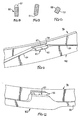
- FIG. 5 is a top view illustrating the split ring retainer employed;
- FIG. 6 is an enlarged partial view showing the split section of the ring;
- FIG. 7 is an enlarged partial view showing the ring detent mechanism and a section of the ring on each side of detent mechanism;
- FIG. 8 is a sectional view taken along lines 8-8 in Fig. 7;
- FIG. 9 is a sectional view taken along lines 9-9 in Fig. 5;
- FIG. 10 is a sectional view taken along lines 10-10 in Fig. 5;
- FIG. 11 is an enlarged partial perspective view showing the detent mechanism;
- FIG. 12 is an enlarged partial view in perspective showing a raised lug on the split ring in engagement with a rib located upon a locking key segment;
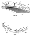
- FIG. 13 is an enlarged partial view in perspective showing the split section of the ring and a portion of the outer air seal of a turbine rotor stage; and
- FIG. 14 is an enlarged partial view in perspective showing the detent mechanism.
- Referring now to Fig. 1, an annular outer air seal assembly is shown generally at 10 as applied to an inner surface of a turbine casing 11. As an integral part of the
inner surface 12 there is a circumferentially disposedmounting flange 13 having a radially inwardly extending leg 14 and an axially extendingleg 16. Themounting flange 13 forms a circumferential groove 17 between aninner surface 18 of the turbine casing 11 and anouter surface 19 of the axially extendingleg 16. Also formed on the inner side of the turbine casing 11 are thecircumferential slots 21 and 22. - The above described structure within the turbine casing is adapted to support a blade outer air seal (BOAS) shown at 23 in Fig. 1. As will be seen in Figs. 1-3, the BOAS comprises a plurality of circumferentially spaced,
interconnected segments 24 having a generally axially extendingseal portion 26, a plurality of radially disposed arms 27 (See Fig. 1) and a plurality ofhanger elements 28. The arms 27 are hidden in Fig. 3 but are shown in Fig. 1, whereas thehanger elements 28 are hidden in Fig. 1, but shown in Fig. 3. Thehanger elements 28 fit into the circumferential groove 17 and are supported by the axially extending 1eg 16. - As shown in Fig. 3, in addition to the arms 27 and
hanger elements 28, theBOAS segments 24 have other support elements 29 disposed toward their upstream end which are mounted in appropriate structure on the inner side of the turbine casing 11 but not shown in Fig. 1. - Although the axially extending
leg 16, in cooperation with thehanger elements 28, acts to position and support theBOAS segments 24 in the radial direction, it is also necessary to locate and fix these seal elements in the axial direction. This is accomplished by the use of an angle-shaped seal 31 and asplit retention ring 32. The angle-shaped seal 31 is dual purpose in that it provides, in conjunction with thesplit retention ring 32, a physical locating device for the BOAS, as well as providing sealing for the higher pressure air outboard of the BOAS which is used to cool and purge the BOAS. - Referring again to Fig. 1 and Fig. 3, the angle-
shaped seal 31 comprises a radially disposed arcuate-shaped panel 33 with a plurality of axially extendinghooks 34. As shown in Fig. 3, thehooks 34 fit circumferentially between thehanger elements 28 of the BOAS, with both being disposed within the groove 17 as shown in Fig. 1. For purposes of assembly, theBOAS segments 24 are first assembled from the rear of the engine, with thehanger elements 28 sliding into the circumferential groove 17, and then the multiple arc-shaped angle-shaped seal segments 31 are slid behind and hook into the same groove 17 to either side of theBOAS hanger elements 28. - Also projecting from the radially disposed arcuate-
shaped panels 33 are forwardly extending flanges 36 and rearwardly extending flanges or ribs 37. The ends of the forwardly extending flanges 36 fit into slots 38 on the rear side of the arm elements 27 as shown in Fig. 1. It is these forwardly extending flanges 36 which bear against the slots 38 to hold the BOAS in its axial position. Theretention ring 32 then interacts with the rearwardly extending flanges 37 and the circumferential slot 22 to lock the assembly in its position. - A preferred embodiment of the locking arrangement is described with reference to Figures 5-14, and will be described further below.
- In addition to the function of the forwardly extending flange 36 acting to bias the BOAS forwardly, an advantage is taken of the tendency for the BOAS arm element 27 to be rotated as the BOAS is biased rearwardly because of the pressure differential across the BOAS, to aid in the sealing function. That is, as the BOAS is moved rearwardly against the forwardly extending flange 36, the angle-
shaped seal 31 is rotated about the fulcrum that exists between the legouter surface 19 and apad 39 on the axially extendinghook 34. With the rotation of the angle-shaped seal, a radiallyouter surface 41 of the arcuate-shaped panel 33 is biased against theinner surface 18 of the casing 11 to provide a sealing relationship that prevents the leakage of cooling air rearwardly. Thus, with the engagement of these two surfaces and those of the forwardly extending flanges 36 in the slot 38, a seal is created to prevent the rearward flow of the cooling air. - One of the noteworthy concepts of the above described design is the relatively long axially extending
hooks 34. Due to tolerance stack up, other retention schemes considered would not provide any consistent axial stop location for the BOAS. For example, a radial segment fitting into the case but extending inwardly enough to provide the seal could have an axial position tolerance of 0.002 inches (0.05 mm) with the case slot. With the long arm, this distance could translate into a substantial amplification of the tolerance on the piece, allowing the BOAS to slide aft by a significantly greater amount. With the current design however, any aft motion of the BOAS produces a tilt on the angle-shaped seal. With a similar 0.002 inch (0.05 mm) tolerance on the axially positioning of the axially extendinghooks 34, the BOAS can slide aft by no more than 0.002 inches (0.05 mm). Accordingly, tight control of the tolerance in the radial distance between the casinginner surface 18 and the axially extending legouter surface 19 is critical to ensure a consistent preload of the L-seal. Further, the effect of segment to segment variations in part length is also minimized with this design. - In addition to the length of the axially extending
hooks 34, the radial height of thepanel 33 is important. This radial height is preferably set to provide a sealing surface against the inboard portion of the BOAS and for ease of assembly. - Referring now to Fig. 4, there are a pair of adjacent angle-
shaped segments 31 and, as will be seen, there is a gap 42 that exists both between the adjacent axially extendinghooks 34 and between the adjacent arcuate-shaped panels 33. With respect to the gap between the adjacent arcuate-shaped panels 33, leakage of cooling air can occur therebetween, and therefore it is necessary to seal this gap. This is accomplished by way of a shiplap arrangement that is obtained by attachingsmall plates 43 that cover the gap 42 and extend in overlapping relationship over the adjacent arcuate-shapedpanels 33. Theplates 43 are preferably attached by welding or the like. Alternatively, theplates 43 could be produced by machining them from the solid segments. - With reference to the preferred locking arrangement, as illustrated in Figs. 5-4, a preferred
split retaining ring 32 is generally circular in form. The ring includes abody section 53 having a given thickness (t). The ring contains asplit section 55 that is cut at an angle (Fig. 13) that allows the ring to be flexed outwardly when a sufficient outwardly directed force is applied to the ring. The ring is fabricated of a high strength metal having a resiliency such the ring wants to return to its initial unload condition once the flexing force is released. Many types of spring steel are available that provide both this type of high-strength and resiliency. - A series of lugs 57-57 are integrally located upon the
inner surface 58 of the ring body. The lugs are circumferentially spaced about the ring body so that each lug on the ring can be seated upon one of a plurality of rib-like seats 59 formed on the flanges or ribs 37 that extend outwardly from each of theseal segments 31. The outer surfaces 60 on the ribs generally approximate a circle having a first diameter. Theinner surfaces 61 of thelugs 57 generally approximate a second circle having a second diameter that is less than the first diameter approximated by the lugs when the ring is in an unloaded condition. Accordingly, the ring must be forced outwardly in order to seat the lugs upon the seats of the key segments as best illustrated in Figs. 11-14. - The body section of the ring is slidably contained within the radially disposed annular groove 22 formed in the turbine casing 11 and surrounds the seats on the
seal segments 31 so that the ring can move radially in assembly as the lugs are mounted upon the seats. Aninclined ramp 65 is located on either side of each lug. To assemble the ring upon the seats of theseal segments 31, the body of the ring is placed over the seat with the lugs being adjacent to the ribs. The ring is then rotated in the groove 22 to guide the seat over the inclined ramps associated with each lug forcing the ring outwardly in a radial direction until the seats are mounted upon the top of each of the lugs. Groove 22 is aligned with each of the locking segments such thatside wall 68 of the ring is in contact with the outer wall 70 of each locking segment when the segments are in the locked position. As should now be evident, the expanded ring is now unable to move radially out of the groove 22 in the casing, and correspondingly, the key segments are unable to move axially out of the locking position. The seats on theseal segments 31 insure that the split ring will always be loaded radially in an outward direction to prevent the ring from moving inwardly. The ring as illustrated in Fig. 10 is split at an angle to provide a sufficient gap between the angled split surfaces so that thermal expansion of the ring will not produce any additional compressive loading on the ring during engine operation which might otherwise produce thermal jacking of the ring that might result in a premature failure of the ring. The ramp feature also allows the ring to be installed or removed in either a clockwise or a counterclockwise direction without the need of special tools. - A detent mechanism generally referenced 80 (Fig. 11) is furnished to prevent improper installation of the ring. The detent mechanism, as illustrated in Fig. 11, includes a raised platform located on the inside of the ring that is diametrically opposed from the split in the ring. A circumferentially extended
recess 82 is located in the top surface of the platform and is dimensioned to snuggly receive therein akeeper 83 which is located on one of the seal segments. In practice, a seat as described in detail above may serve as the detent keeper. The detent platform again is furnished with aninclined ramp 84 on either side of seat which facilitates the guiding of the keeper into therecess 82 as the ring is rotated withingroove 19. The ramps again allow the ring to be rotated in either direction during installation and removal and serve to minimize galling and wear on the detent mechanisms. The detent mechanism provides a positive tangential locking capability to the ring which resists thermal movement of the ring that might produce an unbalanced load resulting in the ring being fractured and requiring its replacement. - With further reference to Fig. 11, a section of the
ring body 86 located on either side of the detent mechanism has a reduced thickness which allows the ring to adjust its position upon seats positioned on either side of the detent. This in turn facilitates proper positioning of the seats upon the lugs and allows for closure control over the ring's flexibility. - While the present invention has been particularly shown and described with reference to the preferred mode as illustrated in the drawing, it will be understood by one skilled in the art that various changes in detail may be effected therein without departing from the scope of the invention as defined by the claims.
Claims (12)
- Apparatus for securing an outer seal assembly (23) of a turbine rotor stage to a turbine casing (11) comprising:a plurality of radially outwardly extending arms (27) on said outer seal assembly, said arms (27) having a rear surface and a plurality of axially forwardly extending hanger elements (28);a mounting flange (13) formed on the inner side (18) of said casing (11) and having a radially inwardly extending leg (14) and an axially rearwardly extending leg (16) with a radially outer surface (19) which, together with the inner side (18) of said casing (11), forms a circumferential groove (17) for receiving said hanger elements (28) therein;a plurality of arcuate elements (31) having an angle-shaped cross section and comprising a radially extending panel (33) with a plurality of axially forwardly extending hooks (34) adapted to be received in said circumferential groove (17) and having at least one axially forwardly extending flange (36) for engaging said arm rear surface of said outer seal assembly (23); anda lock (32) for locking said outer seal assembly (23) and angle-shaped elements in their installed positions within said grooves (17).
- Apparatus as set forth in claim 1 and further wherein said outer seal assembly arm rear surface includes at least one slot (38) for receiving said axially forwardly extending flange (36).
- Apparatus as set forth in claim 1 or 2 wherein said arcuate elements further include an axially rearwardly extending flange (37) for engaging with said locking means (32).
- Apparatus as set forth in any preceding claim and further wherein said arcuate elements include a radially outer edge (41) which engages an inner surface (18) of said casing (11) in a sealing relationship.
- Apparatus as set forth in claim 4 wherein, when said outer seal assembly arm rear surface is urged rearwardly against said forwardly extending flange (36) of said arcuate element, the arcuate element is rotated in a counterclockwise direction with the radially outer surface (19) of said rearwardly extending leg (16) acting as a fulcrum, thereby resulting in the radially outer edge (41) of said arcuate element being biased against said casing inner surface (18).
- Apparatus as set forth in claim 5 wherein said axially forwardly extending hooks (34) of said arcuate elements include a pad (39) for engaging said axially rearwardly extending leg (16) to thereby facilitate the rotational movement.
- Apparatus for locking a blade outer air seal (BOAS) (23) in place about a turbine rotor stage for a jet engine that includes:an engine casing (11) that surrounds said rotor stage, said casing (11) having a circular radially disposed wall (14) and an axially disposed groove (17) adjacent said wall, said groove (17) having an inner wall (19) and an outer wall (18), said outer wall (18) extending outwardly beyond the entrance to said groove (17);an annular hanger for supporting the BOAS (23), said hanger having a plurality of circumferentially spaced hanger elements (28) that extend into said groove (17), said hanger (28) further having a front face that is adjacent to the radial wall (14) of the casing (11) and an opposing rear face;an annular segmented assembly wherein each segment (31) includes an arcuate shaped radially disposed panel (33) and a plurality of hooks (34) attached to said panel (33) and passing between the hanger elements (28) into said groove (17), each panel (33) having a first sealing pad (41) extending along its radially outer rim that rests in sealing contact against the outer wall (18) of said groove (17) and a second sealing pad (36) extending along the front face of the panel (33) that rests in sealing contact against the rear face of the annular hanger (28);each hook (34) having a contact portion (39) which engages said groove inner wall (19) which acts as a fulcrum to apply a torque to the associated panel (33); andmeans (32) to prevent axial movement of said segmented assembly.
- Apparatus as set forth in claim 7 and further wherein said hanger rear face includes at least one slot (38) for receiving said second sealing pad (36).
- Apparatus as set forth in claim 7 or 8 wherein said arcuate shaped radially disposed panel (33) further includes a rearwardly extending flange (37) for engagement with said means (32) for preventing axial movement.
- A method for securing an outer seal assembly (23) of a turbine rotor stage to the turbine casing comprising the steps of:providing a plurality of radially outwardly extending arms (27) on said outer seal assembly, said arms having a rear surface and a plurality of axially forwardly extending hanger elements (28);providing a mounting flange (13) on the inner side of said casing (11) and having a radially inwardly extending leg (14) and an axially rearwardly extending leg (16) with a radially outer surface (19) which, together with the inner side of said casing (11), forms a circumferential groove (17) for receiving said hanger elements (28) therein;providing a plurality of arcuate elements having an angle-shaped cross section comprising a radially extending panel (33) with a plurality of axially forward extending hooks (34) adapted to be received in said circumferential groove (17) and having at least one axially forwardly extending flange (36) for engaging said arm rear surface of said outer seal assembly (23); andlocking said outer seal assembly (23) and said angle-shaped elements in their installed positions within said groove (17).
- A method as set forth in claim 10 and including the step of providing a radially outer edge (41) on said arcuate element, with said radially outer edge (41) engaging an inner surface (18) of said casing (11) in a sealing relationship.
- A method as set forth in claim 10 or 11 wherein said locking step is accomplished with a locking mechanism (32) disposed near the radially outer portion of said arcuate element such that, when the arm rear surface is urged against the axially forwardly extending flange (36) of said arcuate elements, the arcuate element is allowed to rotate so as to thereby bias said radially outer edge against said casing inner surface.
Applications Claiming Priority (2)
| Application Number | Priority Date | Filing Date | Title |
|---|---|---|---|
| US11/091,204 US7334980B2 (en) | 2005-03-28 | 2005-03-28 | Split ring retainer for turbine outer air seal |
| US11/091,172 US7721433B2 (en) | 2005-03-28 | 2005-03-28 | Blade outer seal assembly |
Publications (3)
| Publication Number | Publication Date |
|---|---|
| EP1707749A2 true EP1707749A2 (en) | 2006-10-04 |
| EP1707749A3 EP1707749A3 (en) | 2010-04-21 |
| EP1707749B1 EP1707749B1 (en) | 2012-02-22 |
Family
ID=36071082
Family Applications (1)
| Application Number | Title | Priority Date | Filing Date |
|---|---|---|---|
| EP06250466A Expired - Lifetime EP1707749B1 (en) | 2005-03-28 | 2006-01-27 | Blade outer seal assembly |
Country Status (1)
| Country | Link |
|---|---|
| EP (1) | EP1707749B1 (en) |
Cited By (6)
| Publication number | Priority date | Publication date | Assignee | Title |
|---|---|---|---|---|
| US8152455B2 (en) | 2007-07-06 | 2012-04-10 | Rolls-Royce Deutschland Ltd & Co Kg | Suspension arrangement for the casing shroud segments |
| CN103375193A (en) * | 2012-04-18 | 2013-10-30 | 通用电气公司 | Stator seal for turbine rub avoidance |
| WO2013163581A1 (en) * | 2012-04-27 | 2013-10-31 | General Electric Company | System and method of limiting axial movement between a hanger and a fairing assembly in a turbine assembly |
| WO2015047478A2 (en) | 2013-07-23 | 2015-04-02 | United Technologies Corporation | Radial position control of case support structure with splined connection |
| US20170096911A1 (en) * | 2015-10-02 | 2017-04-06 | Honeywell International Inc. | Compliant coupling systems and methods for shrouds |
| EP2961930B1 (en) * | 2013-02-26 | 2020-05-27 | United Technologies Corporation | Edge treatment for blade outer air seal segment |
Families Citing this family (1)
| Publication number | Priority date | Publication date | Assignee | Title |
|---|---|---|---|---|
| EP3097273B1 (en) | 2014-01-20 | 2019-11-06 | United Technologies Corporation | Retention clip for a blade outer air seal |
Citations (2)
| Publication number | Priority date | Publication date | Assignee | Title |
|---|---|---|---|---|
| WO1999030009A1 (en) | 1997-12-05 | 1999-06-17 | Pratt & Whitney Canada Corp. | Seal assembly for a gas turbine engine |
| EP1079076A2 (en) | 1999-08-25 | 2001-02-28 | General Electric Company | Shroud assembly having c-clip retainer |
Family Cites Families (1)
| Publication number | Priority date | Publication date | Assignee | Title |
|---|---|---|---|---|
| US5639210A (en) * | 1995-10-23 | 1997-06-17 | United Technologies Corporation | Rotor blade outer tip seal apparatus |
-
2006
- 2006-01-27 EP EP06250466A patent/EP1707749B1/en not_active Expired - Lifetime
Patent Citations (2)
| Publication number | Priority date | Publication date | Assignee | Title |
|---|---|---|---|---|
| WO1999030009A1 (en) | 1997-12-05 | 1999-06-17 | Pratt & Whitney Canada Corp. | Seal assembly for a gas turbine engine |
| EP1079076A2 (en) | 1999-08-25 | 2001-02-28 | General Electric Company | Shroud assembly having c-clip retainer |
Cited By (12)
| Publication number | Priority date | Publication date | Assignee | Title |
|---|---|---|---|---|
| US8152455B2 (en) | 2007-07-06 | 2012-04-10 | Rolls-Royce Deutschland Ltd & Co Kg | Suspension arrangement for the casing shroud segments |
| CN103375193A (en) * | 2012-04-18 | 2013-10-30 | 通用电气公司 | Stator seal for turbine rub avoidance |
| US10215033B2 (en) | 2012-04-18 | 2019-02-26 | General Electric Company | Stator seal for turbine rub avoidance |
| WO2013163581A1 (en) * | 2012-04-27 | 2013-10-31 | General Electric Company | System and method of limiting axial movement between a hanger and a fairing assembly in a turbine assembly |
| CN104471197A (en) * | 2012-04-27 | 2015-03-25 | 通用电气公司 | Systems and methods for limiting axial movement between a pylon and a spinner assembly within a turbine assembly |
| CN104471197B (en) * | 2012-04-27 | 2016-05-11 | 通用电气公司 | Systems and methods for limiting axial movement between a pylon and a spinner assembly within a turbine assembly |
| US10344621B2 (en) | 2012-04-27 | 2019-07-09 | General Electric Company | System and method of limiting axial movement between components in a turbine assembly |
| EP2961930B1 (en) * | 2013-02-26 | 2020-05-27 | United Technologies Corporation | Edge treatment for blade outer air seal segment |
| WO2015047478A2 (en) | 2013-07-23 | 2015-04-02 | United Technologies Corporation | Radial position control of case support structure with splined connection |
| EP3025042A4 (en) * | 2013-07-23 | 2016-08-17 | United Technologies Corp | RADIALLY POSITION CONTROL OF CANNEL CONNECTED CARTER SUPPORT STRUCTURE |
| US20170096911A1 (en) * | 2015-10-02 | 2017-04-06 | Honeywell International Inc. | Compliant coupling systems and methods for shrouds |
| US10030542B2 (en) * | 2015-10-02 | 2018-07-24 | Honeywell International Inc. | Compliant coupling systems and methods for shrouds |
Also Published As
| Publication number | Publication date |
|---|---|
| EP1707749A3 (en) | 2010-04-21 |
| EP1707749B1 (en) | 2012-02-22 |
Similar Documents
| Publication | Publication Date | Title |
|---|---|---|
| US7941920B2 (en) | Blade outer seal assembly and method | |
| US7334980B2 (en) | Split ring retainer for turbine outer air seal | |
| US8800133B2 (en) | Gas turbine systems involving rotor bayonet coverplates and tools for installing such coverplates | |
| US7520718B2 (en) | Seal and locking plate for turbine rotor assembly between turbine blade and turbine vane | |
| US6435820B1 (en) | Shroud assembly having C-clip retainer | |
| EP1323899B1 (en) | Gasturbine with a supplemental seal for the chordal hinge seal | |
| JP4612946B2 (en) | Interstage seal holding device and assembly | |
| JP5185426B2 (en) | Rotor section for turbomachine rotor | |
| CA2513054C (en) | Multi-point seal | |
| US7153098B2 (en) | Attachment for a bladed rotor | |
| JPH05156967A (en) | Gas turbine vane assembly hermetic support | |
| US7811054B2 (en) | Shroud configuration having sloped seal | |
| US7032904B2 (en) | Inner air seal anti-rotation device | |
| EP1707749B1 (en) | Blade outer seal assembly | |
| EP0668434B1 (en) | Gas turbine engine component retention | |
| CN115190947B (en) | Mounting flanged vacuum pump to vacuum system | |
| US12188563B2 (en) | Mistake-proofing for hydrostatic seal assemblies |
Legal Events
| Date | Code | Title | Description |
|---|---|---|---|
| PUAI | Public reference made under article 153(3) epc to a published international application that has entered the european phase |
Free format text: ORIGINAL CODE: 0009012 |
|
| AK | Designated contracting states |
Kind code of ref document: A2 Designated state(s): AT BE BG CH CY CZ DE DK EE ES FI FR GB GR HU IE IS IT LI LT LU LV MC NL PL PT RO SE SI SK TR |
|
| AX | Request for extension of the european patent |
Extension state: AL BA HR MK YU |
|
| PUAL | Search report despatched |
Free format text: ORIGINAL CODE: 0009013 |
|
| AK | Designated contracting states |
Kind code of ref document: A3 Designated state(s): AT BE BG CH CY CZ DE DK EE ES FI FR GB GR HU IE IS IT LI LT LU LV MC NL PL PT RO SE SI SK TR |
|
| AX | Request for extension of the european patent |
Extension state: AL BA HR MK YU |
|
| RIC1 | Information provided on ipc code assigned before grant |
Ipc: F01D 9/04 20060101ALI20100315BHEP Ipc: F01D 25/24 20060101ALI20100315BHEP Ipc: F01D 11/08 20060101AFI20100315BHEP |
|
| 17P | Request for examination filed |
Effective date: 20100610 |
|
| 17Q | First examination report despatched |
Effective date: 20100708 |
|
| AKX | Designation fees paid |
Designated state(s): DE GB |
|
| REG | Reference to a national code |
Ref country code: DE Ref legal event code: R079 Ref document number: 602006027726 Country of ref document: DE Free format text: PREVIOUS MAIN CLASS: F01D0009040000 Ipc: F01D0011080000 |
|
| RIC1 | Information provided on ipc code assigned before grant |
Ipc: F01D 9/04 20060101ALI20110616BHEP Ipc: F01D 25/24 20060101ALI20110616BHEP Ipc: F01D 11/08 20060101AFI20110616BHEP |
|
| GRAP | Despatch of communication of intention to grant a patent |
Free format text: ORIGINAL CODE: EPIDOSNIGR1 |
|
| GRAS | Grant fee paid |
Free format text: ORIGINAL CODE: EPIDOSNIGR3 |
|
| GRAA | (expected) grant |
Free format text: ORIGINAL CODE: 0009210 |
|
| AK | Designated contracting states |
Kind code of ref document: B1 Designated state(s): DE GB |
|
| REG | Reference to a national code |
Ref country code: GB Ref legal event code: FG4D |
|
| REG | Reference to a national code |
Ref country code: DE Ref legal event code: R081 Ref document number: 602006027726 Country of ref document: DE Owner name: UNITED TECHNOLOGIES CORP. (N.D.GES.D. STAATES , US Free format text: FORMER OWNER: UNITED TECHNOLOGIES CORP. (N.D.GES.D. STAATES DELAWARE), HARTFORD, CONN., US |
|
| REG | Reference to a national code |
Ref country code: DE Ref legal event code: R096 Ref document number: 602006027726 Country of ref document: DE Effective date: 20120419 |
|
| PLBE | No opposition filed within time limit |
Free format text: ORIGINAL CODE: 0009261 |
|
| STAA | Information on the status of an ep patent application or granted ep patent |
Free format text: STATUS: NO OPPOSITION FILED WITHIN TIME LIMIT |
|
| 26N | No opposition filed |
Effective date: 20121123 |
|
| REG | Reference to a national code |
Ref country code: DE Ref legal event code: R097 Ref document number: 602006027726 Country of ref document: DE Effective date: 20121123 |
|
| REG | Reference to a national code |
Ref country code: DE Ref legal event code: R082 Ref document number: 602006027726 Country of ref document: DE Representative=s name: SCHMITT-NILSON SCHRAUD WAIBEL WOHLFROM PATENTA, DE |
|
| REG | Reference to a national code |
Ref country code: DE Ref legal event code: R082 Ref document number: 602006027726 Country of ref document: DE Representative=s name: SCHMITT-NILSON SCHRAUD WAIBEL WOHLFROM PATENTA, DE Ref country code: DE Ref legal event code: R081 Ref document number: 602006027726 Country of ref document: DE Owner name: UNITED TECHNOLOGIES CORP. (N.D.GES.D. STAATES , US Free format text: FORMER OWNER: UNITED TECHNOLOGIES CORPORATION, HARTFORD, CONN., US |
|
| PGFP | Annual fee paid to national office [announced via postgrant information from national office to epo] |
Ref country code: DE Payment date: 20191218 Year of fee payment: 15 |
|
| REG | Reference to a national code |
Ref country code: DE Ref legal event code: R119 Ref document number: 602006027726 Country of ref document: DE |
|
| PG25 | Lapsed in a contracting state [announced via postgrant information from national office to epo] |
Ref country code: DE Free format text: LAPSE BECAUSE OF NON-PAYMENT OF DUE FEES Effective date: 20210803 |
|
| PGFP | Annual fee paid to national office [announced via postgrant information from national office to epo] |
Ref country code: GB Payment date: 20241219 Year of fee payment: 20 |
|
| REG | Reference to a national code |
Ref country code: GB Ref legal event code: PE20 Expiry date: 20260126 |