EP1707454A1 - Seatbelt retractor assembly - Google Patents
Seatbelt retractor assembly Download PDFInfo
- Publication number
- EP1707454A1 EP1707454A1 EP06004059A EP06004059A EP1707454A1 EP 1707454 A1 EP1707454 A1 EP 1707454A1 EP 06004059 A EP06004059 A EP 06004059A EP 06004059 A EP06004059 A EP 06004059A EP 1707454 A1 EP1707454 A1 EP 1707454A1
- Authority
- EP
- European Patent Office
- Prior art keywords
- actuator
- profile portion
- seatbelt retractor
- guide surface
- acceleration
- Prior art date
- Legal status (The legal status is an assumption and is not a legal conclusion. Google has not performed a legal analysis and makes no representation as to the accuracy of the status listed.)
- Granted
Links
- 230000001133 acceleration Effects 0.000 claims abstract description 43
- 230000007704 transition Effects 0.000 description 7
- 238000006073 displacement reaction Methods 0.000 description 5
- 230000004044 response Effects 0.000 description 4
- 230000035945 sensitivity Effects 0.000 description 3
- 230000008859 change Effects 0.000 description 2
- 230000007423 decrease Effects 0.000 description 2
- 238000000034 method Methods 0.000 description 2
- 230000003466 anti-cipated effect Effects 0.000 description 1
- 230000009286 beneficial effect Effects 0.000 description 1
- 238000006243 chemical reaction Methods 0.000 description 1
- 230000000694 effects Effects 0.000 description 1
- 230000002093 peripheral effect Effects 0.000 description 1
- 230000009467 reduction Effects 0.000 description 1
- 230000004043 responsiveness Effects 0.000 description 1
Images




Classifications
-
- B—PERFORMING OPERATIONS; TRANSPORTING
- B60—VEHICLES IN GENERAL
- B60R—VEHICLES, VEHICLE FITTINGS, OR VEHICLE PARTS, NOT OTHERWISE PROVIDED FOR
- B60R22/00—Safety belts or body harnesses in vehicles
- B60R22/34—Belt retractors, e.g. reels
- B60R22/36—Belt retractors, e.g. reels self-locking in an emergency
- B60R22/40—Belt retractors, e.g. reels self-locking in an emergency responsive only to vehicle movement
Definitions
- a seatbelt for a motor vehicle typically has a seatbelt retractor that retracts the belt into a housing and winds the belt upon a spool.
- the spool winds a retraction spring, which later retracts the belt onto the spool.
- the seatbelt retractor has a lock that prevents the seatbelt from extending further.
- the lock may be actuated by an inertial sensor, which responds to changes in vehicle speed during the crash. When a large deceleration is detected, the inertial sensor triggers the lock to lock the spool and secures the safety belt in place during the crash.
- the inertial sensor has an inertial sensor mass that moves in response to changes in speed of the vehicle. This mass is mechanically linked to the lock by an actuator. When the inertial sensor mass moves, the actuator moves and causes movement of a locking pawl that locks the lock when the inertial sensor mass has moved in excess of a predetermined amount.
- the actuator rests on a surface of the mass. This surface is angled so that movement of the mass causes rapid movement of the actuator and consequently the locking pawl. While rapid movement of the components of the inertial sensor and lock are desirable for safety, this same feature causes undesirable noise during normal vehicle operation.
- This need is met by a seatbelt retractor according to claim 1 having an inertial sensor that detects changes in vehicle speed using an inertial sensor mass, which is linked to a seatbelt retractor locking pawl by an actuator.
- the actuator moves with the mass by riding on its surface.
- the surface of the mass is shaped to guide the actuator in a manner that controls its acceleration and therefore noise. Movement of the actuator is controlled by the shape of the guide surface of the inertial mass.
- the actuator may have more than one acceleration rate as it moves across the guide surface. By controlling the rate of acceleration of the actuator, noise is also controlled without reducing the overall sensor sensitivity significantly, in some cases actually increasing the initial sensor reaction sensitivity.
- FIG. 1 is a side view of a new seatbelt retractor assembly 10.
- the seatbelt retractor assembly 10 has a seatbelt retractor 14 housing a seatbelt 18.
- the seatbelt retractor assembly 10 has a locking pawl 22, which selectively engages a locking wheel 28.
- the locking wheel 28 has teeth to engage the locking pawl 22.
- the seatbelt retractor 14 prevents the seatbelt 18 from extending further from seatbelt retractor 14.
- the seatbelt retractor 14 has an inertial sensor, here an inertial sensor mass 30, which is responsive to vehicle acceleration.
- the inertial sensor mass 30 rests on a sensor housing 24, here shown schematically and tips in the direction of either arrow R or arrow S in response to vehicle acceleration.
- the inertial sensor mass 30 is linked to the locking pawl 22 by an actuator 26.
- An arm causes the locking pawl 22 to engage or disengage the locking wheel 28 depending upon the position of the inertial sensor mass 30.
- the locking pawl 22 is shown schematically as a separate component from the actuator 26, the locking pawl 22 and actuator 26 may, in fact, be a single part.
- the actuator 26 interacts with a guide surface 34 through an actuator surface 54.
- the actuator surface 54 has an actuator curvature 58.
- Figure 1 illustrates the inertial sensor mass 30 in an unlocked condition.
- the actuator 26 maintains the locking pawl 22 in an unlocked condition, allowing the seatbelt 18 to be withdrawn from the seatbelt retractor 14.
- the actuator 26 is pivotally mounted by a pivot 19 so as to rotate in the direction of arrow R in response to movement of the inertial sensor mass 30 in the direction of arrow P or in the direction of arrow Q.
- the inertial sensor mass 30 responds by moving either in the direction of arrow P or in the direction of arrow Q. In either direction, the actuator 26 moves in the direction of arrow R.
- inertial sensor mass 30 is shown having moved in the direction of arrow P from the unlocking position 38 shown in Figure 1 to a locking position 42. Movement of the inertial sensor mass 30 has caused the actuator 26 to move in the direction of arrow R from the position shown in Figure 1. This movement of the actuator 26 causes the locking pawl 22 to engage the teeth of the locking wheel 28. The return movement of the inertial sensor mass 30 in the direction of arrow Q towards the unlocking position 38 causes a return of the actuator 26 in the direction of arrow S to the position shown in Figure 1.
- the new inertial sensor mass 30 has a unique guide surface 34 that controls the displacement, velocity and acceleration of the actuator 26 in the direction of arrow R and arrow S.
- the displacement, velocity and acceleration of the actuator 26 and consequently the locking pawl 22 By controlling the displacement, velocity and acceleration of the actuator 26 and consequently the locking pawl 22, noise from these moving components may be greatly reduced without reducing sensitivity significantly.
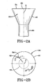
- a guide surface 34 according to a first embodiment of the invention is shown in Figures 2A and 2B.
- the guide surface 34 is located on a wide portion 46 above a narrow portion 50. While the figures show a particular shape of a sensor upon which guide surface 34 sits, guide surface 34 may be implemented as any shape such as a ball or cylinder shape.
- the guide surface 34 comprises an inner profile region having a low angle or generally flat inner profile 62 near the center or the "near zero" vehicle acceleration location X.
- the prior art sensor has a conical guide surface inclined or sloped at 15° or greater.
- the invention employs a guide surface 34 inclined at a surface angle ⁇ having less than 15° relative to the horizontal plane at the near zero vehicle acceleration preferably less than 10° or even 5°, as shown about 0° or flat.
- This inner profile 62 can extend across the entire guide surface as shown in Figure 2A and 2B. In such a case the pivotal movement of the actuator is minimized at low vehicle accelerations of insufficient size to tilt the sensor mass 30 but great enough to cause vibrations which can lead to rattle noises, While the slope of the inner profile region 62 should be less than 15°, a lower slope, like a slope angle ⁇ of 0° or flat, maximizes the benefits of reduced movement of the actuator 26 at the at rest or near zero vehicle acceleration condition.
- the entire guide surface 34 may have the same profile as the inner profile 62. Alternatively other more inclined profiles may be used in combination with the inner profile 62 as will be discussed.
- the surface angle ⁇ and its relationship to the pivotal motion will be explained in greater detail, however, as the actuator 26 is pivoted as the guide surface 34 and sensor mass 30 tilt during a vehicle acceleration input the angle naturally changes.
- the surface angle ⁇ is shown as the angle of the guide surface 34 at the point of contact with the actuator surface 54 as measured from a horizontal plane as noted in figure 1 the angle ⁇ is 0°. This is how the guide surface of the sensor mass 30 appears relative to the horizontal plane.
- the actuator 26 pivots about the pivot 19 and contact between the actuator surface 54 and the guide surface 34 changes such that the contact angle ⁇ is progressively moving in relation to the sensor filt angle ⁇ .
- a cam like guide surface 34 to control the movement of the actuator 26 by the following methods.
- a line 80 is drawn through the actuator 26 and guide surface 34 contact point 100 and the pivot point 102 of the sensor mass 30 relative to the housing 24, a second line 82 perpendicular to line 80 is drawn through the contact point 100.
- a third line 84 is drawn tangent to the guide surface 34 at the contact point 100.
- An angle ⁇ ' between the line 84 and the line 82 defines a moving guide surface contact angle ⁇ ' tangent to the guide surface 34 as the sensor 30 tilts about the pivot point 102 at that point of contact 100. Accordingly the moving contact angle ⁇ ' is progressively changing as the sensor mass 30 pivots about this pivot point 102.
- the low or small ⁇ ' inclinations cause a slow acceleration of the actuator 26 while large angles ⁇ ' of positive slope result in faster accelerations and negative sloping curvatures can achieve decelerations of the actuator 26.
- a cam like guide surface similar to the guide surface 36 having features progressively outward from the at rest or near zero vehicle acceleration location X a complete control of the movement of the actuator 26 is possible.
- the second and third embodiments show the application of this methodology to create various actuator acceleration profiles to reduce noise.
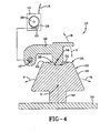
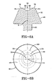
- Figures 4 - 6B illustrate an inertial sensor mass 32 according to a second embodiment of the invention.
- the sensor 32 has a guide surface 35 having an outer profile region 64, the outer profile region 64 initiates on a portion of guide surface 35 as contact with the actuator surface 54 along at least a portion of guide surface 35 as the actuator 26 is moved from the at rest and unlocked position 38 to an unlocked but in near proximity, to the full locked position 42.
- the sensor guide surface 35 in figures 4 and 5 has an inner profile 69 inward of the outer profile 64 which may include any particular curvature having a resulting positive acceleration of the actuator.
- a conical sloped depression 69 having an angle or slope ⁇ of 15° or greater or a slope angle ⁇ of less than 15°.
- FIGS 7-10C illustrate a third and preferred embodiment of the invention.
- the sensor 33 illustrated in figure 7 has a guide surface 36 having the inner profile 62 of the first embodiment and an outer profile 64 of the second embodiment with a transition profile 63 interposed between the two profiles 62, 64 respectively.
- the actuator 26 is not shown, but is described in relation to the profile regions of the guide surface 36. It being understood how the guide surface interacts with the actuator 26 from the previous discussion.
- the transition profile 63 has an inner portion 65 having steep slope curve, as shown the curve progressively increases in slope from the inner profile 62 and at an inflection point 72 thereafter progressively decreases in slope to decrease the rate of acceleration of the actuator 26 as the sensor mass 33 tilts toward the locking position 42.
- the circumferential outer portion 66 of the transition profile 63 then smoothly connects to the outer profile 64 wherein the deceleration of the actuator 26 reaches a maximum prior to reaching the locking position 42.
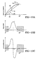
- Figures 10A, 10B and 10C are graphs exemplary of the displacement, velocity and the acceleration profile of the actuator 26 being guided by the preferred guide surface 36.
- the guide surface 36 has three primary profile portions, the inner profile portion 62 from X to A; the transition profile portion 63 from A to B, and B to C; and the outer profile portion 64 from C to D and D to E. These portions have different curvatures.
- the inner profile portion 62 at X to A curves away from the curvature 58 of the actuator surface 54 and is generally flat. Movement over this portion of the inertial sensor mass 33 causes little acceleration and movement of the actuator 26. Because the actuator 26 is in contact with portion X to A in the unlocking position 38, the actuator 26 will have reduced responsiveness for this region. The actuator 26 and locking pawl 22 move very little, thereby reducing noise generation.
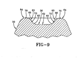
- portion X to A defining the inner profile 62 is shown in Figure 9 as generally flat, i.e, having little or zero curvature, other curvatures that curve away from the curvature 58 of the actuator surface 54 may be used to achieve the same object of causing little movement of the actuator 26 in the direction of arrow R when the inertial sensor mass 33 teeters in the direction of either arrow P or arrow Q,
- portion X to A need only have a curvature greater than the curvature of actuator surface 54 to reduce movement of actuator 26 and thereby reduce noise. It may be preferable for portion X to A to have a curvature opposite the curvature 58 of actuator surface 54.
- the inertial sensor mass 33 moves the guide surface 36 to the locking position 42.
- the actuator 26 will pass from the inner profile portion X to A to the transition profile 63 first portion 65 at location A to B, which is curved upwards having a radius of curvature on the same side and toward the actuator surface 54 to increase acceleration of the actuator 26 to lock the seatbelt retractor 14.
- Portion 65 at location A to B is then followed by a second portion of the transition profile B to C, which curves with a radius of curvature in an opposite direction, i.e., originating inside the profile and downwards away from the actuator surface 54, extending to the curvature to location D from location A to B to thereby slow the actuator 26.
- the actuator 26 is further slowed by a generally flat curved portion of the outer profile 64 from location C to D and is rapidly slowed by a deceleration profile at an outermost portion of the outer profile 64 from location D to E, which also curves downwards. Movement of the actuator surface 54 across the guide surface 36 can be controlled to have different levels of acceleration so that the actuator 26 may initially move slowly in response to movement of the inertial sensor mass 33 guide surface 36, then rapidly, and then slowly. During normal vehicle operation, the actuator 26 will move very little if at all due to portion X to A.
- the actuator 26 moves rapidly because of the curvature of portion 65 at location A to B and is slowed at locations B to C, C to D and D to E to gently place the locking pawl 22 into a locking position 42 rather than rapidly as with conventional designs.
- the guide surface 36 causes the actuator 26 to have different levels of acceleration.
- the actuator 26 For the portion 62 between X and A, the actuator 26 has an acceleration S 1 , which is very little acceleration, if any. Over the portion 65 between A to B, the actuator is imparted with an acceleration S 2 , which is a rapid acceleration and faster than the acceleration of S 1 .
- the curvature causes the actuator 26 to encounter an acceleration level S 3 , which decelerates the actuator 26.
- the actuator 26 In the portion 62 from C to D, the actuator 26 has little to no acceleration and is provided with an acceleration rate S 4 .
- the actuator 26 In the region of the outer profile 64 from D to E, the actuator 26 is decelerated at a deceleration S 5 to rapidly slow the actuator 26. In the outer portions of this region it is anticipated that the actuator 26 should not be moving because the locking pawl 22 should engage the locking wheel 28 prior to reaching this portion.
- the profiles of the guide surface 34, 35, 36 may take any variety of shapes or curvatures it is believed desirable that the inner profile 62 have a low inclination or flat surface, the transition profile 63 provide a rapid acceleration or steeply curved portion and the outer profile 64 provide a deceleration or negatively sloped curvature to slow the movement of the actuator 26 just prior to locking.
- the features of the inner profile 62 shown in figures 1-3 can be used without the outer profiles 64 or with combination of various profiles to achieve the at near 0° vehicle acceleration noise reduction.
- the outer profile 64 shown in Figures 4 - 6B can be used to soften contact impacts at locking with, or without, the inner profile 62 as disclosed.
- the inner and outer profiles 62, 64 when used in combination provide the beneficial aspects of both profiles, particularly when used with the transitional profile 63 as illustrated in figures 7 through 10C.
Landscapes
- Engineering & Computer Science (AREA)
- Mechanical Engineering (AREA)
- Automotive Seat Belt Assembly (AREA)
Abstract
mass (30, 32, 33) has a guide surface (34, 35, 36) for interacting with the actuator (26). The guide surface (34, 35, 36) moves between an unlocking position in which the actuator (26) unlocks the seatbelt retractor (14) and a locking position in which the actuator (26) locks the seatbelt retractor (14). The guide surface (30) has an inner profile portion (62) and at least an outer profile portion (64). The actuator (26) is in contact with the inner profile portion (62) in the unlocking position while moving into contact with the outer profile portion (64) as the actuator (26) moves towards the locking position. The inner profile
portion (62) causes a different acceleration of the actuator (26) than the outer profile portion (64).
Description
- A seatbelt for a motor vehicle typically has a seatbelt retractor that retracts the belt into a housing and winds the belt upon a spool. When the belt is drawn or protracted from its housing, the spool winds a retraction spring, which later retracts the belt onto the spool.
- In a crash the seatbelt retractor has a lock that prevents the seatbelt from extending further. The lock may be actuated by an inertial sensor, which responds to changes in vehicle speed during the crash. When a large deceleration is detected, the inertial sensor triggers the lock to lock the spool and secures the safety belt in place during the crash.
- The inertial sensor has an inertial sensor mass that moves in response to changes in speed of the vehicle. This mass is mechanically linked to the lock by an actuator. When the inertial sensor mass moves, the actuator moves and causes movement of a locking pawl that locks the lock when the inertial sensor mass has moved in excess of a predetermined amount. The actuator rests on a surface of the mass. This surface is angled so that movement of the mass causes rapid movement of the actuator and consequently the locking pawl. While rapid movement of the components of the inertial sensor and lock are desirable for safety, this same feature causes undesirable noise during normal vehicle operation.
- A need exists for a seatbelt retractor that reduces noise from the foregoing moveable parts. This need is met by a seatbelt retractor according to
claim 1 having an inertial sensor that detects changes in vehicle speed using an inertial sensor mass, which is linked to a seatbelt retractor locking pawl by an actuator. The actuator moves with the mass by riding on its surface. In contrast to conventional designs, the surface of the mass is shaped to guide the actuator in a manner that controls its acceleration and therefore noise. Movement of the actuator is controlled by the shape of the guide surface of the inertial mass. The actuator may have more than one acceleration rate as it moves across the guide surface. By controlling the rate of acceleration of the actuator, noise is also controlled without reducing the overall sensor sensitivity significantly, in some cases actually increasing the initial sensor reaction sensitivity. - Figure 1 is a side view of the new seatbelt retractor.
- Figure 2A is a side view of the inertial sensor of Figure 1.
- Figure 2B is an overhead view of the inertial sensor mass of Figure 1.
- Figure 3 illustrates the seatbelt retractor of Figure 1 in a locked condition.
- Figure 4 is a side view of a second embodiment of the new seatbelt retractor in an unlocked condition.
- Figure 5 illustrates the seatbelt retractor of Figure 4 in a locked condition.
- Figure 6A is a side cross sectional view of an inertial sensor of Figure 4.
- Figure 6B is an overhead view of the second embodiment inertial sensor.
- Figure 7 is a side view of a third embodiment inertial sensor combining in initial profile of first embodiment with the outer profile of the second embodiment via an interposed transitional profile.
- Figure 8 is an overhead view of the third embodiment.
- Figure 9 is an enlarged view of the guide surface taken from Figure 7.
- Figures 10A, 10B and 10C are exemplary graphical representations of the actuator displacement, velocity and acceleration respectively as the inertial sensor tilts to the fully locked position from the unlocked.
- Figure 1 is a side view of a new seatbelt
retractor assembly 10. The seatbeltretractor assembly 10 has a seatbeltretractor 14 housing aseatbelt 18. Like conventional seatbelt retractors, the seatbeltretractor assembly 10 has alocking pawl 22, which selectively engages alocking wheel 28. Thelocking wheel 28 has teeth to engage thelocking pawl 22. When thelocking pawl 22 engages thelocking wheel 22, the seatbeltretractor 14 prevents theseatbelt 18 from extending further from seatbeltretractor 14. - The seatbelt
retractor 14 has an inertial sensor, here aninertial sensor mass 30, which is responsive to vehicle acceleration. Theinertial sensor mass 30 rests on asensor housing 24, here shown schematically and tips in the direction of either arrow R or arrow S in response to vehicle acceleration. Theinertial sensor mass 30 is linked to thelocking pawl 22 by anactuator 26. An arm causes thelocking pawl 22 to engage or disengage thelocking wheel 28 depending upon the position of theinertial sensor mass 30. While thelocking pawl 22 is shown schematically as a separate component from theactuator 26, thelocking pawl 22 andactuator 26 may, in fact, be a single part. In Figures 1 and 3, theactuator 26 interacts with aguide surface 34 through anactuator surface 54. Theactuator surface 54 has anactuator curvature 58. - Figure 1 illustrates the
inertial sensor mass 30 in an unlocked condition. When in this position, theactuator 26 maintains thelocking pawl 22 in an unlocked condition, allowing theseatbelt 18 to be withdrawn from theseatbelt retractor 14. Theactuator 26 is pivotally mounted by apivot 19 so as to rotate in the direction of arrow R in response to movement of theinertial sensor mass 30 in the direction of arrow P or in the direction of arrow Q. During quick acceleration or deceleration of a vehicle, such as a crash, theinertial sensor mass 30 responds by moving either in the direction of arrow P or in the direction of arrow Q. In either direction, theactuator 26 moves in the direction of arrow R. - In Figure 3 the
inertial sensor mass 30 is shown having moved in the direction of arrow P from theunlocking position 38 shown in Figure 1 to alocking position 42. Movement of theinertial sensor mass 30 has caused theactuator 26 to move in the direction of arrow R from the position shown in Figure 1. This movement of theactuator 26 causes thelocking pawl 22 to engage the teeth of thelocking wheel 28. The return movement of theinertial sensor mass 30 in the direction of arrow Q towards theunlocking position 38 causes a return of theactuator 26 in the direction of arrow S to the position shown in Figure 1. - In contrast to conventional inertial sensor masses, the new
inertial sensor mass 30 has aunique guide surface 34 that controls the displacement, velocity and acceleration of theactuator 26 in the direction of arrow R and arrow S. By controlling the displacement, velocity and acceleration of theactuator 26 and consequently thelocking pawl 22, noise from these moving components may be greatly reduced without reducing sensitivity significantly. - A
guide surface 34 according to a first embodiment of the invention is shown in Figures 2A and 2B. In Figure 2A, theguide surface 34 is located on awide portion 46 above anarrow portion 50. While the figures show a particular shape of a sensor upon whichguide surface 34 sits,guide surface 34 may be implemented as any shape such as a ball or cylinder shape. Theguide surface 34 comprises an inner profile region having a low angle or generally flatinner profile 62 near the center or the "near zero" vehicle acceleration location X. The prior art sensor has a conical guide surface inclined or sloped at 15° or greater. The invention employs aguide surface 34 inclined at a surface angle α having less than 15° relative to the horizontal plane at the near zero vehicle acceleration preferably less than 10° or even 5°, as shown about 0° or flat. Thisinner profile 62 can extend across the entire guide surface as shown in Figure 2A and 2B. In such a case the pivotal movement of the actuator is minimized at low vehicle accelerations of insufficient size to tilt thesensor mass 30 but great enough to cause vibrations which can lead to rattle noises, While the slope of theinner profile region 62 should be less than 15°, a lower slope, like a slope angle α of 0° or flat, maximizes the benefits of reduced movement of theactuator 26 at the at rest or near zero vehicle acceleration condition. Theentire guide surface 34 may have the same profile as theinner profile 62. Alternatively other more inclined profiles may be used in combination with theinner profile 62 as will be discussed. The surface angle α and its relationship to the pivotal motion will be explained in greater detail, however, as theactuator 26 is pivoted as theguide surface 34 andsensor mass 30 tilt during a vehicle acceleration input the angle naturally changes. For simplicity the surface angle α is shown as the angle of theguide surface 34 at the point of contact with theactuator surface 54 as measured from a horizontal plane as noted in figure 1 the angle α is 0°. This is how the guide surface of thesensor mass 30 appears relative to the horizontal plane. As the sensor mass tilts theactuator 26 pivots about thepivot 19 and contact between theactuator surface 54 and theguide surface 34 changes such that the contact angle α is progressively moving in relation to the sensor filt angle θ. - It is possible to design a cam like
guide surface 34 to control the movement of theactuator 26 by the following methods. In figure 3 aline 80 is drawn through theactuator 26 and guidesurface 34contact point 100 and thepivot point 102 of thesensor mass 30 relative to thehousing 24, asecond line 82 perpendicular toline 80 is drawn through thecontact point 100. Athird line 84 is drawn tangent to theguide surface 34 at thecontact point 100. An angle α' between theline 84 and theline 82 defines a moving guide surface contact angle α' tangent to theguide surface 34 as thesensor 30 tilts about thepivot point 102 at that point ofcontact 100. Accordingly the moving contact angle α' is progressively changing as thesensor mass 30 pivots about thispivot point 102. The low or small α' inclinations cause a slow acceleration of theactuator 26 while large angles α' of positive slope result in faster accelerations and negative sloping curvatures can achieve decelerations of theactuator 26. By selecting a cam like guide surface similar to theguide surface 36 having features progressively outward from the at rest or near zero vehicle acceleration location X a complete control of the movement of theactuator 26 is possible. The second and third embodiments show the application of this methodology to create various actuator acceleration profiles to reduce noise. - Figures 4 - 6B illustrate an
inertial sensor mass 32 according to a second embodiment of the invention. Thesensor 32 has aguide surface 35 having anouter profile region 64, theouter profile region 64 initiates on a portion ofguide surface 35 as contact with theactuator surface 54 along at least a portion ofguide surface 35 as theactuator 26 is moved from the at rest andunlocked position 38 to an unlocked but in near proximity, to the full lockedposition 42. Thesensor guide surface 35 in figures 4 and 5 has aninner profile 69 inward of theouter profile 64 which may include any particular curvature having a resulting positive acceleration of the actuator. In figures 6A and 6B a conical slopeddepression 69 having an angle or slope α of 15° or greater or a slope angle α of less than 15°. In figure 5 at alocation 70 on the peripheral inner boundary of theouter profile 64 the positive acceleration of theinertial sensor mass 32 changes to a negative deceleration and thesensor guide surface 35 has a reverse slope change in curvature causing a deceleration of the actuator. The change in curvature creates a negative slope or angle inclination α' relative to theguide surface 35 at thecontact point 100 as measured relative tolines line 82 being perpendicular toline 80, as previously discussed. This results in the movement of theactuator 26 to slow down or decelerate as thesensor mass 32 tips at thepivot point 102 to the fully closed position as shown this is at a tilt angle θ of about 20°, although the angle θ can be any angle selected for the proper tilt of a particular inertial sensor. As acceleration changes from positive to negative at theinflection location outer profile 64, the speed ofactuator 26 movement slows. The effect of this slowing is a softer impact force occurs as theactuator 26 moves the lockingpawl 22 into engagement with the locking teeth. This in turn reduces noises caused by locking. - Figures 7-10C illustrate a third and preferred embodiment of the invention. The
sensor 33 illustrated in figure 7 has aguide surface 36 having theinner profile 62 of the first embodiment and anouter profile 64 of the second embodiment with atransition profile 63 interposed between the twoprofiles actuator 26 is not shown, but is described in relation to the profile regions of theguide surface 36. It being understood how the guide surface interacts with the actuator 26 from the previous discussion. Thetransition profile 63 has aninner portion 65 having steep slope curve, as shown the curve progressively increases in slope from theinner profile 62 and at aninflection point 72 thereafter progressively decreases in slope to decrease the rate of acceleration of theactuator 26 as thesensor mass 33 tilts toward the lockingposition 42. The circumferentialouter portion 66 of thetransition profile 63 then smoothly connects to theouter profile 64 wherein the deceleration of theactuator 26 reaches a maximum prior to reaching the lockingposition 42. - Figures 10A, 10B and 10C are graphs exemplary of the displacement, velocity and the acceleration profile of the
actuator 26 being guided by thepreferred guide surface 36. - In Figures 7 and 8, the
guide surface 36 has three primary profile portions, theinner profile portion 62 from X to A; thetransition profile portion 63 from A to B, and B to C; and theouter profile portion 64 from C to D and D to E. These portions have different curvatures. Theinner profile portion 62 at X to A curves away from thecurvature 58 of theactuator surface 54 and is generally flat. Movement over this portion of theinertial sensor mass 33 causes little acceleration and movement of theactuator 26. Because theactuator 26 is in contact with portion X to A in the unlockingposition 38, theactuator 26 will have reduced responsiveness for this region. Theactuator 26 and lockingpawl 22 move very little, thereby reducing noise generation. - While portion X to A defining the
inner profile 62 is shown in Figure 9 as generally flat, i.e, having little or zero curvature, other curvatures that curve away from thecurvature 58 of theactuator surface 54 may be used to achieve the same object of causing little movement of theactuator 26 in the direction of arrow R when theinertial sensor mass 33 teeters in the direction of either arrow P or arrow Q, In Figure 9, portion X to A need only have a curvature greater than the curvature ofactuator surface 54 to reduce movement ofactuator 26 and thereby reduce noise. It may be preferable for portion X to A to have a curvature opposite thecurvature 58 ofactuator surface 54. By curving theguide surface 36 away from thecurvature 58 ofactuator surface 54, movement of theinertial sensor mass 33 causes little or no displacement of theactuator 26 in the direction of arrow R for this region of theinertial sensor mass 33. - In a crash the
inertial sensor mass 33 moves theguide surface 36 to thelocking position 42. Theactuator 26 will pass from the inner profile portion X to A to thetransition profile 63first portion 65 at location A to B, which is curved upwards having a radius of curvature on the same side and toward theactuator surface 54 to increase acceleration of theactuator 26 to lock theseatbelt retractor 14.Portion 65 at location A to B is then followed by a second portion of the transition profile B to C, which curves with a radius of curvature in an opposite direction, i.e., originating inside the profile and downwards away from theactuator surface 54, extending to the curvature to location D from location A to B to thereby slow theactuator 26. Theactuator 26 is further slowed by a generally flat curved portion of theouter profile 64 from location C to D and is rapidly slowed by a deceleration profile at an outermost portion of theouter profile 64 from location D to E, which also curves downwards. Movement of theactuator surface 54 across theguide surface 36 can be controlled to have different levels of acceleration so that theactuator 26 may initially move slowly in response to movement of theinertial sensor mass 33guide surface 36, then rapidly, and then slowly. During normal vehicle operation, theactuator 26 will move very little if at all due to portion X to A. In a crash theactuator 26 moves rapidly because of the curvature ofportion 65 at location A to B and is slowed at locations B to C, C to D and D to E to gently place the lockingpawl 22 into alocking position 42 rather than rapidly as with conventional designs. - In Figure 8, the
guide surface 36 causes theactuator 26 to have different levels of acceleration. For theportion 62 between X and A, theactuator 26 has an acceleration S1, which is very little acceleration, if any. Over theportion 65 between A to B, the actuator is imparted with an acceleration S2, which is a rapid acceleration and faster than the acceleration of S1. In theportion 66 from B to C, the curvature causes theactuator 26 to encounter an acceleration level S3, which decelerates theactuator 26. In theportion 62 from C to D, theactuator 26 has little to no acceleration and is provided with an acceleration rate S4. In the region of theouter profile 64 from D to E, theactuator 26 is decelerated at a deceleration S5 to rapidly slow theactuator 26. In the outer portions of this region it is anticipated that theactuator 26 should not be moving because the lockingpawl 22 should engage thelocking wheel 28 prior to reaching this portion. - While the profiles of the
guide surface inner profile 62 have a low inclination or flat surface, thetransition profile 63 provide a rapid acceleration or steeply curved portion and theouter profile 64 provide a deceleration or negatively sloped curvature to slow the movement of theactuator 26 just prior to locking. - The features of the
inner profile 62 shown in figures 1-3 can be used without theouter profiles 64 or with combination of various profiles to achieve the at near 0° vehicle acceleration noise reduction. Theouter profile 64 shown in Figures 4 - 6B can be used to soften contact impacts at locking with, or without, theinner profile 62 as disclosed. The inner andouter profiles transitional profile 63 as illustrated in figures 7 through 10C.
Claims (10)
- A seatbelt retractor assembly (10) comprising: a seatbelt retractor (14); an actuator (26) for locking and unlocking the seatbelt retractor (14); an inertial sensor mass (30, 32, 33) for detecting changes in vehicle acceleration, the inertial sensor mass (30, 32, 33) having a guide surface (34, 35, 36) for interacting with an actuator surface (54) to move the actuator (26); the guide surface movable (34, 35, 36) between an unlocking position wherein the actuator (26) unlocks the seatbelt retractor (14) and a locking position wherein the actuator (26) locks the seatbelt retractor (14); characterized by the guide surface (34, 35, 36) comprising an inner profile portion (62, 69) and an outer profile portion (64), the actuator surface (54) being in contact with the inner profile portion (62, 69) in the unlocking position and continuing in contact with the outer profile portion (64) as the actuator (26) moves toward the locking position, the outer profile portion (64) causing a deceleration, thereby slowing the actuator (26) prior to the locking position.
- A seatbelt retractor assembly (10) according to Claim 1 wherein the inner profile portion (62, 69) has a different curvature than the outer profile portion (64).
- A seatbelt retractor assembly (10) according to Claim 2 wherein the inner profile portion (62, 69) curves in an opposite direction relative to the outer profile portion (64).
- A seatbelt retractor assembly (10) according to Claim 1 wherein the outer profile portion (64) causes a deceleration of the actuator surface (54) and the inner profile portion (62, 69) causes an acceleration of the actuator surface (54).
- A seatbelt retractor assembly (10) according to Claim 1 wherein the inner profile portion (62, 69) is generally flat and the outer profile portion (64) is curved.
- A seatbelt retractor assembly (10) according to Claim 5 wherein the guide surface (34, 35, 36) further comprises a transitional profile portion (63), the transitional profile portion (63) being located between the inner profile portion (62, 69) and outer profile portion (64) and causing a different acceleration of the actuator (26) than the inner profile portion (62, 69) and the outer profile portion (64).
- A seatbelt retractor assembly (10) according to Claim 6 wherein the transitional profile portion (63) has a first curvature toward the actuator (26) and a second curvature away from the actuator (26) spaced by an inflection point.
- A seatbelt retractor assembly (10) according to Claim 7 wherein the transitional profile portion (63), has the first curvature closer to the inner profile portion (62, 69) and causing a more rapid acceleration of the actuator (26) than the inner profile portion (62, 69).
- A seatbelt retractor assembly (10) according to Claim 8 wherein the transitional portion (63) has the second curvature closer to the outer profile portion (64) and cause a slower acceleration of the actuator (26) than the first curvature.
- A seatbelt retractor assembly (10) according to any of Claims 1 - 9 wherein the inner profile portion (62, 69) has a surface curvature inclined at an angle (α) of less than 15°.
Applications Claiming Priority (1)
| Application Number | Priority Date | Filing Date | Title |
|---|---|---|---|
| US11/092,278 US7377464B2 (en) | 2005-03-29 | 2005-03-29 | Seatbelt retractor having an inertial sensor weight with a guide surface |
Publications (2)
| Publication Number | Publication Date |
|---|---|
| EP1707454A1 true EP1707454A1 (en) | 2006-10-04 |
| EP1707454B1 EP1707454B1 (en) | 2008-04-02 |
Family
ID=36169072
Family Applications (1)
| Application Number | Title | Priority Date | Filing Date |
|---|---|---|---|
| EP06004059A Expired - Lifetime EP1707454B1 (en) | 2005-03-29 | 2006-02-28 | Seatbelt retractor assembly |
Country Status (4)
| Country | Link |
|---|---|
| US (3) | US7377464B2 (en) |
| EP (1) | EP1707454B1 (en) |
| DE (1) | DE602006000838T2 (en) |
| ES (1) | ES2302264T3 (en) |
Families Citing this family (18)
| Publication number | Priority date | Publication date | Assignee | Title |
|---|---|---|---|---|
| US7263750B2 (en) | 2005-06-09 | 2007-09-04 | Amsafe, Inc. | Buckle assembly having single release for multiple belt connectors |
| WO2010037103A1 (en) | 2008-09-29 | 2010-04-01 | Amsafe, Inc. | Tensioning apparatuses for occupant restraint systems and associated systems and methods |
| US8469401B2 (en) | 2009-02-23 | 2013-06-25 | Amsafe, Inc. | Seat harness pretensioner |
| US8393645B2 (en) | 2009-11-02 | 2013-03-12 | Amsafe Commercial Products, Inc. | Devices for adjusting tension in seat belts and other restraint system webs, and associated methods |
| US8683666B2 (en) | 2009-11-04 | 2014-04-01 | Amsafe Commercial Products, Inc. | Restraint system buckle components having tactile surfaces, and associated methods of use and manufacture |
| US8627554B1 (en) | 2010-05-03 | 2014-01-14 | Amsafe, Inc. (Phoenix Group) | Buckle assemblies with swivel and dual release features and associated methods of use and manufacture |
| US8777323B2 (en) | 2010-07-20 | 2014-07-15 | Amsafe, Inc. | Restraint harnesses and associated methods of use and manufacture |
| USD655223S1 (en) | 2010-09-15 | 2012-03-06 | Amsafe Commercial Products, Inc. | Buckle assembly |
| USD661619S1 (en) | 2010-09-15 | 2012-06-12 | Amsafe Commercial Products, Inc. | Buckle assembly |
| US9022483B2 (en) | 2012-06-07 | 2015-05-05 | Shield Restraint Systems, Inc. | Seatbelt buckle tongue assembly |
| EP2958453A4 (en) | 2013-02-19 | 2016-07-27 | Amsafe Inc | Buckle assemblies with lift latches and associated methods and systems |
| US9277788B2 (en) | 2013-02-19 | 2016-03-08 | Amsafe, Inc. | Dual release buckle assemblies and associated systems and methods |
| DE102014111923B4 (en) * | 2014-08-20 | 2017-03-30 | Volkswagen Aktiengesellschaft | Armrest with crash protection |
| WO2016100566A1 (en) | 2014-12-16 | 2016-06-23 | Shield Restraint Systems, Inc. | Web adjusters for use with restraint systems and associated methods of use and manufacture |
| US10604259B2 (en) | 2016-01-20 | 2020-03-31 | Amsafe, Inc. | Occupant restraint systems having extending restraints, and associated systems and methods |
| US9814282B2 (en) | 2016-02-02 | 2017-11-14 | Shield Restraint Systems, Inc. | Harsh environment buckle assemblies and associated systems and methods |
| US10611334B2 (en) | 2017-02-07 | 2020-04-07 | Shield Restraint Systems, Inc. | Web adjuster |
| WO2020168131A1 (en) * | 2019-02-17 | 2020-08-20 | Said Nakhla | Universal child seat base for isofix installation |
Citations (4)
| Publication number | Priority date | Publication date | Assignee | Title |
|---|---|---|---|---|
| US4101093A (en) * | 1976-11-11 | 1978-07-18 | Allied Chemical Corporation | Friction dampened pendulum sensor |
| US4344589A (en) * | 1980-10-23 | 1982-08-17 | The Firestone Tire & Rubber Company | Tandem dual spool retractor structure |
| US5507449A (en) * | 1994-08-12 | 1996-04-16 | Trw Vehicle Safety Systems Inc. | Seat belt retractor with noise suppression |
| US6164581A (en) * | 1999-01-29 | 2000-12-26 | Breed Automotive Technology, Inc. | Low noise self-compensating vehicle sensor and retractor |
Family Cites Families (9)
| Publication number | Priority date | Publication date | Assignee | Title |
|---|---|---|---|---|
| US2000402A (en) * | 1932-08-12 | 1935-05-07 | Servidor Company | Cabinet |
| US4084840A (en) * | 1976-02-23 | 1978-04-18 | Allied Chemical Corporation | Vehicle sensitive retractor |
| JPS5617772A (en) * | 1979-07-20 | 1981-02-19 | Honda Motor Co Ltd | Motorcycle |
| US4343444A (en) * | 1980-10-03 | 1982-08-10 | Allied Corporation | Tilt compensating pendulum for seat mounted retractor |
| JPS6118542A (en) | 1984-07-06 | 1986-01-27 | N S K Warner Kk | emergency rock retractor |
| US4726540A (en) | 1986-11-17 | 1988-02-23 | General Motors Corporation | Variable sensitivity seat belt retractor |
| US4765559A (en) * | 1987-07-07 | 1988-08-23 | American Safety Equipment Corporation | Synchronized safety belt retractor with structural control locking means |
| US6688547B1 (en) | 2002-11-04 | 2004-02-10 | Breed Automotive Technology, Inc. | Self compensating inertia sensor |
| JP3777358B2 (en) | 2003-03-06 | 2006-05-24 | 本田技研工業株式会社 | Seat belt device |
-
2005
- 2005-03-29 US US11/092,278 patent/US7377464B2/en not_active Expired - Fee Related
-
2006
- 2006-02-28 DE DE602006000838T patent/DE602006000838T2/en not_active Expired - Fee Related
- 2006-02-28 ES ES06004059T patent/ES2302264T3/en not_active Expired - Lifetime
- 2006-02-28 EP EP06004059A patent/EP1707454B1/en not_active Expired - Lifetime
-
2008
- 2008-03-28 US US12/079,552 patent/US7461806B2/en not_active Expired - Fee Related
- 2008-03-28 US US12/079,553 patent/US7464892B2/en not_active Expired - Fee Related
Patent Citations (4)
| Publication number | Priority date | Publication date | Assignee | Title |
|---|---|---|---|---|
| US4101093A (en) * | 1976-11-11 | 1978-07-18 | Allied Chemical Corporation | Friction dampened pendulum sensor |
| US4344589A (en) * | 1980-10-23 | 1982-08-17 | The Firestone Tire & Rubber Company | Tandem dual spool retractor structure |
| US5507449A (en) * | 1994-08-12 | 1996-04-16 | Trw Vehicle Safety Systems Inc. | Seat belt retractor with noise suppression |
| US6164581A (en) * | 1999-01-29 | 2000-12-26 | Breed Automotive Technology, Inc. | Low noise self-compensating vehicle sensor and retractor |
Also Published As
| Publication number | Publication date |
|---|---|
| US20060219833A1 (en) | 2006-10-05 |
| ES2302264T3 (en) | 2008-07-01 |
| US7461806B2 (en) | 2008-12-09 |
| US7377464B2 (en) | 2008-05-27 |
| US7464892B2 (en) | 2008-12-16 |
| DE602006000838T2 (en) | 2009-05-07 |
| EP1707454B1 (en) | 2008-04-02 |
| US20080203209A1 (en) | 2008-08-28 |
| US20080203208A1 (en) | 2008-08-28 |
| DE602006000838D1 (en) | 2008-05-15 |
Similar Documents
| Publication | Publication Date | Title |
|---|---|---|
| US7461806B2 (en) | Seatbelt retractor having an inertial sensor weight with a guide surface | |
| US6802470B2 (en) | Seat belt retractor | |
| KR20090074076A (en) | Seat belt retractor with torsion bar | |
| US6739625B2 (en) | Seat-belt guide anchor | |
| US7455256B2 (en) | Seatbelt retractor having a cushioned sensor actuator | |
| US20130181430A1 (en) | Self-Locking Belt Retractor | |
| JP2024522483A (en) | Vehicle sensor device and seat belt retractor using same | |
| US8052219B2 (en) | Seat belt retractor and seat belt device using the same | |
| US6631865B2 (en) | Seat belt retractor | |
| US7013736B2 (en) | Sensor for belt retractor | |
| US6213420B1 (en) | Safety belt apparatus with an acceleration sensor | |
| US6247365B1 (en) | Safety restraint | |
| EP1048536B1 (en) | A seat belt retractor | |
| EP1558473B1 (en) | Self compensating inertia sensor | |
| JP3512045B2 (en) | Acceleration sensor | |
| KR200237316Y1 (en) | Arm type seat belt | |
| EP1552992A1 (en) | Belt retractor | |
| KR20040051139A (en) | Retractor device of seatbelt for automobile | |
| KR101315885B1 (en) | Device of seat belt | |
| EP3984836B1 (en) | A vehicle-sensitive sensor and self-locking belt-retractor | |
| KR20060068930A (en) | Webbing lock structure of car seat belt height adjusting device | |
| GB2326813A (en) | Improvements in or relating to an acceleration detector | |
| US20050248144A1 (en) | Vehicle acceleration sensor for seat belt retractor |
Legal Events
| Date | Code | Title | Description |
|---|---|---|---|
| PUAI | Public reference made under article 153(3) epc to a published international application that has entered the european phase |
Free format text: ORIGINAL CODE: 0009012 |
|
| 17P | Request for examination filed |
Effective date: 20060612 |
|
| AK | Designated contracting states |
Kind code of ref document: A1 Designated state(s): AT BE BG CH CY CZ DE DK EE ES FI FR GB GR HU IE IS IT LI LT LU LV MC NL PL PT RO SE SI SK TR |
|
| AX | Request for extension of the european patent |
Extension state: AL BA HR MK YU |
|
| GRAP | Despatch of communication of intention to grant a patent |
Free format text: ORIGINAL CODE: EPIDOSNIGR1 |
|
| AKX | Designation fees paid |
Designated state(s): DE ES FR GB IT |
|
| GRAS | Grant fee paid |
Free format text: ORIGINAL CODE: EPIDOSNIGR3 |
|
| RBV | Designated contracting states (corrected) |
Designated state(s): DE ES FR GB IT SE |
|
| GRAA | (expected) grant |
Free format text: ORIGINAL CODE: 0009210 |
|
| AK | Designated contracting states |
Kind code of ref document: B1 Designated state(s): DE ES FR GB IT SE |
|
| REG | Reference to a national code |
Ref country code: GB Ref legal event code: FG4D |
|
| REF | Corresponds to: |
Ref document number: 602006000838 Country of ref document: DE Date of ref document: 20080515 Kind code of ref document: P |
|
| REG | Reference to a national code |
Ref country code: SE Ref legal event code: TRGR |
|
| REG | Reference to a national code |
Ref country code: ES Ref legal event code: FG2A Ref document number: 2302264 Country of ref document: ES Kind code of ref document: T3 |
|
| ET | Fr: translation filed | ||
| PLBE | No opposition filed within time limit |
Free format text: ORIGINAL CODE: 0009261 |
|
| STAA | Information on the status of an ep patent application or granted ep patent |
Free format text: STATUS: NO OPPOSITION FILED WITHIN TIME LIMIT |
|
| 26N | No opposition filed |
Effective date: 20090106 |
|
| PGFP | Annual fee paid to national office [announced via postgrant information from national office to epo] |
Ref country code: ES Payment date: 20090223 Year of fee payment: 4 |
|
| PGFP | Annual fee paid to national office [announced via postgrant information from national office to epo] |
Ref country code: DE Payment date: 20090227 Year of fee payment: 4 |
|
| PGFP | Annual fee paid to national office [announced via postgrant information from national office to epo] |
Ref country code: SE Payment date: 20090206 Year of fee payment: 4 |
|
| PGFP | Annual fee paid to national office [announced via postgrant information from national office to epo] |
Ref country code: FR Payment date: 20090206 Year of fee payment: 4 |
|
| GBPC | Gb: european patent ceased through non-payment of renewal fee |
Effective date: 20100228 |
|
| EUG | Se: european patent has lapsed | ||
| REG | Reference to a national code |
Ref country code: FR Ref legal event code: ST Effective date: 20101029 |
|
| PG25 | Lapsed in a contracting state [announced via postgrant information from national office to epo] |
Ref country code: FR Free format text: LAPSE BECAUSE OF NON-PAYMENT OF DUE FEES Effective date: 20100301 |
|
| PG25 | Lapsed in a contracting state [announced via postgrant information from national office to epo] |
Ref country code: DE Free format text: LAPSE BECAUSE OF NON-PAYMENT OF DUE FEES Effective date: 20100901 |
|
| REG | Reference to a national code |
Ref country code: ES Ref legal event code: FD2A Effective date: 20110308 |
|
| PG25 | Lapsed in a contracting state [announced via postgrant information from national office to epo] |
Ref country code: GB Free format text: LAPSE BECAUSE OF NON-PAYMENT OF DUE FEES Effective date: 20100228 |
|
| PG25 | Lapsed in a contracting state [announced via postgrant information from national office to epo] |
Ref country code: ES Free format text: LAPSE BECAUSE OF NON-PAYMENT OF DUE FEES Effective date: 20110307 |
|
| PG25 | Lapsed in a contracting state [announced via postgrant information from national office to epo] |
Ref country code: ES Free format text: LAPSE BECAUSE OF NON-PAYMENT OF DUE FEES Effective date: 20100301 |
|
| PGFP | Annual fee paid to national office [announced via postgrant information from national office to epo] |
Ref country code: IT Payment date: 20090228 Year of fee payment: 4 |
|
| PG25 | Lapsed in a contracting state [announced via postgrant information from national office to epo] |
Ref country code: SE Free format text: LAPSE BECAUSE OF NON-PAYMENT OF DUE FEES Effective date: 20100301 |