EP1707385A2 - Printing apparatus and printing method - Google Patents
Printing apparatus and printing method Download PDFInfo
- Publication number
- EP1707385A2 EP1707385A2 EP06004648A EP06004648A EP1707385A2 EP 1707385 A2 EP1707385 A2 EP 1707385A2 EP 06004648 A EP06004648 A EP 06004648A EP 06004648 A EP06004648 A EP 06004648A EP 1707385 A2 EP1707385 A2 EP 1707385A2
- Authority
- EP
- European Patent Office
- Prior art keywords
- printing
- information
- passbook
- medium
- printing medium
- Prior art date
- Legal status (The legal status is an assumption and is not a legal conclusion. Google has not performed a legal analysis and makes no representation as to the accuracy of the status listed.)
- Withdrawn
Links
- 238000007639 printing Methods 0.000 title claims abstract description 197
- 238000000034 method Methods 0.000 title claims description 8
- 238000012546 transfer Methods 0.000 claims description 75
- 239000010408 film Substances 0.000 description 46
- 238000010438 heat treatment Methods 0.000 description 20
- 230000007246 mechanism Effects 0.000 description 20
- 230000007306 turnover Effects 0.000 description 19
- 230000006870 function Effects 0.000 description 8
- 238000004891 communication Methods 0.000 description 4
- 230000002159 abnormal effect Effects 0.000 description 3
- 239000003086 colorant Substances 0.000 description 3
- 239000000463 material Substances 0.000 description 3
- 238000011144 upstream manufacturing Methods 0.000 description 3
- 230000005856 abnormality Effects 0.000 description 2
- 238000010586 diagram Methods 0.000 description 2
- 239000000049 pigment Substances 0.000 description 2
- 230000008569 process Effects 0.000 description 2
- 230000009467 reduction Effects 0.000 description 2
- 239000010409 thin film Substances 0.000 description 2
- 230000004075 alteration Effects 0.000 description 1
- 230000003247 decreasing effect Effects 0.000 description 1
- 230000007547 defect Effects 0.000 description 1
- 230000002950 deficient Effects 0.000 description 1
- 230000000694 effects Effects 0.000 description 1
- 238000005516 engineering process Methods 0.000 description 1
- 230000004927 fusion Effects 0.000 description 1
- 238000009434 installation Methods 0.000 description 1
- 230000004048 modification Effects 0.000 description 1
- 238000012986 modification Methods 0.000 description 1
- 230000002093 peripheral effect Effects 0.000 description 1
- 238000012545 processing Methods 0.000 description 1
- 238000000926 separation method Methods 0.000 description 1
- 239000002699 waste material Substances 0.000 description 1
Images




Classifications
-
- A—HUMAN NECESSITIES
- A47—FURNITURE; DOMESTIC ARTICLES OR APPLIANCES; COFFEE MILLS; SPICE MILLS; SUCTION CLEANERS IN GENERAL
- A47J—KITCHEN EQUIPMENT; COFFEE MILLS; SPICE MILLS; APPARATUS FOR MAKING BEVERAGES
- A47J37/00—Baking; Roasting; Grilling; Frying
- A47J37/06—Roasters; Grills; Sandwich grills
- A47J37/067—Horizontally disposed broiling griddles
-
- B—PERFORMING OPERATIONS; TRANSPORTING
- B41—PRINTING; LINING MACHINES; TYPEWRITERS; STAMPS
- B41J—TYPEWRITERS; SELECTIVE PRINTING MECHANISMS, i.e. MECHANISMS PRINTING OTHERWISE THAN FROM A FORME; CORRECTION OF TYPOGRAPHICAL ERRORS
- B41J3/00—Typewriters or selective printing or marking mechanisms characterised by the purpose for which they are constructed
- B41J3/28—Typewriters or selective printing or marking mechanisms characterised by the purpose for which they are constructed for printing downwardly on flat surfaces, e.g. of books, drawings, boxes, envelopes, e.g. flat-bed ink-jet printers
- B41J3/283—Typewriters or selective printing or marking mechanisms characterised by the purpose for which they are constructed for printing downwardly on flat surfaces, e.g. of books, drawings, boxes, envelopes, e.g. flat-bed ink-jet printers on bank books or the like
-
- B—PERFORMING OPERATIONS; TRANSPORTING
- B41—PRINTING; LINING MACHINES; TYPEWRITERS; STAMPS
- B41J—TYPEWRITERS; SELECTIVE PRINTING MECHANISMS, i.e. MECHANISMS PRINTING OTHERWISE THAN FROM A FORME; CORRECTION OF TYPOGRAPHICAL ERRORS
- B41J11/00—Devices or arrangements of selective printing mechanisms, e.g. ink-jet printers or thermal printers, for supporting or handling copy material in sheet or web form
- B41J11/0095—Detecting means for copy material, e.g. for detecting or sensing presence of copy material or its leading or trailing end
-
- B—PERFORMING OPERATIONS; TRANSPORTING
- B41—PRINTING; LINING MACHINES; TYPEWRITERS; STAMPS
- B41J—TYPEWRITERS; SELECTIVE PRINTING MECHANISMS, i.e. MECHANISMS PRINTING OTHERWISE THAN FROM A FORME; CORRECTION OF TYPOGRAPHICAL ERRORS
- B41J3/00—Typewriters or selective printing or marking mechanisms characterised by the purpose for which they are constructed
- B41J3/44—Typewriters or selective printing mechanisms having dual functions or combined with, or coupled to, apparatus performing other functions
-
- A—HUMAN NECESSITIES
- A47—FURNITURE; DOMESTIC ARTICLES OR APPLIANCES; COFFEE MILLS; SPICE MILLS; SUCTION CLEANERS IN GENERAL
- A47J—KITCHEN EQUIPMENT; COFFEE MILLS; SPICE MILLS; APPARATUS FOR MAKING BEVERAGES
- A47J36/00—Parts, details or accessories of cooking-vessels
- A47J36/02—Selection of specific materials, e.g. heavy bottoms with copper inlay or with insulating inlay
- A47J36/04—Selection of specific materials, e.g. heavy bottoms with copper inlay or with insulating inlay the materials being non-metallic
Definitions
- the present invention relates to a printing apparatus, which prints a face image and private information of an owner on a medium, such as an ID card for personal authentication and passbook with a built-in memory for wireless data reading/writing, and a printing method.
- a medium such as an ID card for personal authentication and passbook with a built-in memory for wireless data reading/writing
- a passbook printing apparatus using an intermediate transfer film has a printer, a transfer unit, and a reader/writer.
- the printer prints a face image and character information on an image-receiving layer of the intermediate transfer film
- the transfer unit thermally transfers the image-receiving layer of the intermediate transfer film to a printing surface of a passbook
- the reader/writer unit writes necessary data in an IC chip. Namely, this apparatus writes data in the IC chip after printing information on the printing surface of a passbook.
- this apparatus cannot read previously written from the IC chip and reflect it on data to be printed on the printing surface of a passbook.
- the IC chip If the IC chip is found defective when writing data in the IC chip after printing the data on the printing surface, it is unknown whether the IC chip was broken from the beginning or broken in the passbook printing apparatus. In this case, the cause of the defect of the IC chip is unknown, and the responsibility is unclear.
- the passbook is abandoned, and the intermediate transfer film and ink ribbon used for the printing are wasted.
- the abandoned passbook includes the printed private information, and must be carefully handled from the viewpoint of protection of private information.
- the above passbook printing apparatus cannot use data other than the information previously printed in a passbook, and security information to be printed on a passbook can be created only from visible information.
- a printing apparatus comprising a reader which reads identifying information specific to a printing medium from a memory built in the printing medium, and a printer which prints printing information including the identifying information read by the reader on the printing medium.
- a printing apparatus comprising a reader which reads identifying information specific to a printing medium from a memory built in the printing medium, a printing information generator which generates printing information including the identifying information read by the reader, and a printer which prints the printing information generated by the printing information generator in the printing medium.
- a printing method comprising a step of reading identifying information specific to a printing medium from a memory built in the printing medium, and a step of printing printing information including the identifying information read in the reading step on the printing medium.
Landscapes
- Engineering & Computer Science (AREA)
- Food Science & Technology (AREA)
- Accessory Devices And Overall Control Thereof (AREA)
- Record Information Processing For Printing (AREA)
- Financial Or Insurance-Related Operations Such As Payment And Settlement (AREA)
Abstract
Description
- The present invention relates to a printing apparatus, which prints a face image and private information of an owner on a medium, such as an ID card for personal authentication and passbook with a built-in memory for wireless data reading/writing, and a printing method.
- There is a known printing apparatus, which prints a face image and private information of an owner on a passbook with an IC to permit wireless data reading and wring data. (For example, refer to
Jpn. Pat. Appln. KOKAI No. 2002-2154 Japanese Patent No. 3465110 Jpn. Pat. Appln. KOKAI No. 2003-94701 - A passbook printing apparatus using an intermediate transfer film has a printer, a transfer unit, and a reader/writer. In this apparatus, the printer prints a face image and character information on an image-receiving layer of the intermediate transfer film, the transfer unit thermally transfers the image-receiving layer of the intermediate transfer film to a printing surface of a passbook, and the reader/writer unit writes necessary data in an IC chip. Namely, this apparatus writes data in the IC chip after printing information on the printing surface of a passbook.
- Thus, this apparatus cannot read previously written from the IC chip and reflect it on data to be printed on the printing surface of a passbook.
- If the IC chip is found defective when writing data in the IC chip after printing the data on the printing surface, it is unknown whether the IC chip was broken from the beginning or broken in the passbook printing apparatus. In this case, the cause of the defect of the IC chip is unknown, and the responsibility is unclear.
- In this case, the passbook is abandoned, and the intermediate transfer film and ink ribbon used for the printing are wasted. Besides, the abandoned passbook includes the printed private information, and must be carefully handled from the viewpoint of protection of private information.
- Further, the above passbook printing apparatus cannot use data other than the information previously printed in a passbook, and security information to be printed on a passbook can be created only from visible information.
- It is an object of the present invention to provide a printing apparatus and method, which can increase invisibility of printing information and decrease a running cost.
- In order to achieve the above object, according to an aspect of the present invention, there is provided a printing apparatus comprising a reader which reads identifying information specific to a printing medium from a memory built in the printing medium, and a printer which prints printing information including the identifying information read by the reader on the printing medium.
- According to another aspect of the present invention, there is provided a printing apparatus comprising a reader which reads identifying information specific to a printing medium from a memory built in the printing medium, a printing information generator which generates printing information including the identifying information read by the reader, and a printer which prints the printing information generated by the printing information generator in the printing medium.
- According to still another aspect of the present invention, there is provided a printing method comprising a step of reading identifying information specific to a printing medium from a memory built in the printing medium, and a step of printing printing information including the identifying information read in the reading step on the printing medium.
- This summary of the invention does not necessarily describe all necessary features so that the invention may also be a sub-combination of these described features.
- The invention can be more fully understood from the following detailed description when taken in conjunction with the accompanying drawings, in which:
- FIG. 1 is a schematic illustration showing a passbook with a front cover opened;
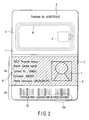
- FIG. 2 is a schematic illustration showing the passbook of FIG. 1, with information printed on a printing page;
- FIG. 3 is a schematic illustration showing a passbook printing apparatus according to an embodiment of the present invention;
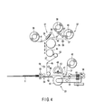
- FIG. 4 is a schematic illustration showing the configuration of a printing unit incorporated in the passbook printing apparatus;
- FIG. 5 is a block diagram showing a control system to control the operation of the passbook of FIG. 3;
- FIG. 6 is a flow chart for explaining the operation of the passbook printing apparatus of FIG. 3; and
- FIG. 7 is a schematic illustration showing a modification of the passbook printing apparatus of FIG. 3.
Hereinafter, embodiments of the present invention will be explained with reference to the accompanying drawings.
FIG. 1 shows anunused passbook 1 with a printing page 2 (printing surface) opened, as an example of printing medium before printing information. In this embodiment, a page next to afront cover 3 is allocated to theprinting page 2. Thefront cover 3 has a previously printedpassbook number 4, for example, as identifying information specific to thepassbook 1. Theprinting page 2 may be allocated to any page.
Thefront cover 3 has a buried IC chip 5 (memory) andantenna 6 for wireless data reading/writing and wireless communication with a reader/writer described later, respectively. TheIC chip 5 includes at least thepassbook number 4 of thepassbook 1 written previously as electronic data. TheIC chip 5 also includes other information such as a serial number of the passbook to identify the passbook written previously as invisible electronic data. TheIC chip 5 andantenna 6 may be buried in other pages than thefront cover 3.
FIG. 2 shows thepassbook 1 with information printed on theprinting page 2. Thepassbook 1 has aprinting area 2a to print a face image and private information of the owner, and areading area 2b having previously printed bar code readable optically through a machine.
Aface image 7 is printed in color and private information is printed in eight black characters in theprinting area 2a. Theprinting area 2a printed with theface image 7 andcharacter data 8 is coated with a protection film (shaded part) 9 given a transparent hologram layer having a specific pattern. Theface image 7 andcharacter data 8 are visible through the pattern of the transparent hologram layer.
In thereading area 2b, encrypted specific face image data is printed, for example. Further, character data such as private information and a bar code of a passbook number specific to thepassbook 1 are printed in thearea 2b. In the following explanation, data such as these encrypted face image and bar code data printed in thereading area 2b is calledsecurity information 10. Thereading area 2b having previously printedsecurity information 10 is coated with a plain transparent protection film.
FIG. 3 shows schematically the configuration of a passbook printing apparatus as an example of a printing apparatus according to an embodiment of the present invention. The passbook printing apparatus has a passbook take-inunit 11 to feed an object or theunused passbook 1 shown in FIG. 1 one by one, and aconveying path 12 to receive and convey thepassbook 1 fed from the passbook take-inunit 11. On theconveying path 12, a wireless IC reader/writer unit 13 (a reading unit), a page turn-overunit 14, a printing unit 15 (a printer), a wireless IC reader/writer unit 16 (a writing unit), and apassbook ejection unit 17 are provided sequentially along the direction of feeding thepassbook 1.
The passbook take-inunit 11 houses a closedpassbook 1 in the state stacked in several numbers, feeds thepassbooks 1 to theconveying path 12 one by one sequentially from the lowermost one, and takes in anotherunused passbook 1. Thepassbook 1 housed in the passbook take-inunit 11 is an unused book as shown in FIG. 1.
The wireless IC reader/writer unit 13 hasfeeding rollers 21 to hold and feed thepassbook 1 through theconveying path 12. At the position above and separated from theconveying path 12, or at the position opposite to the outside surface of thefront cover 3 of thepassbook 1 having the buriedIC chip 5, a wireless IC reader/writer 22 is provided for wireless data communication with theIC chip 5 through theantenna 6 buried in thefront cover 3.
The page turn-overunit 14 hasfeeding rollers 21 to feed thepassbook 1 fed from thewireless IC reader 13 to theconveying path 12 in both forward and backward directions, a turn-over mechanism 23 to open a desired page of thepassbook 1, and a page detector (not shown) to identify the opened page of thepassbook 1 by detecting a page mark given to the page of thepassbook 1 opened by the turn-over mechanism 23.
The turn-over mechanism 23 has abackup plate 24 provided under theconveying path 12, aswing shaft 25 to swing aboutfulcrum 25a provided at the center of the swinging of thebackup plate 24, and a turn-overroller 26 placed above theconveying path 12 and attached rotatably to the top end of theswing shaft 25. When theswing shaft 25 is swung by a not-shown motor to the position indicated by a broken line in the drawing, the turn-overroller 26 is swung and thebackup plate 24 is swung interlocking with the motion of theroller 26. The turn-overroller 26 is rotatable clockwise or counterclockwise by a not-shown motor.
When turning over a page of the passbook with the turn-over mechanism 23, first convey thepassbook 1 to a predetermined position in the turn-over mechanism 23 and stop there, and swing theswing shaft 25 to the left as indicated by a broken line in the drawing and press the turn-overroller 26 onto thepassbook 1. In this time, thebackup plate 24 is oscillated by the swing of theswing shaft 25, and the backside of thepassbook 1 is pushed up by theinclined backup plate 24.
In this state, rotate the turn-overroller 26 pressed to a page of thepassbook 1 on the upstream side of the conveying direction, and start turning over of the uppermost page of the passbook. When the page is swollen just like raised gradually and turned over by a certain extent, stop the rotation of the roller. Return theswing shaft 25 to the position indicated by a solid line in the drawing, and rotate again the turn-overroller 26, and turn over the page completely onto theroller 26.
Convey thepassbook 1 in the upstream direction of the conveying direction, open completely the page turned over onto the turn-overroller 26, detect the page mark of the opened page by a not-shown page detector, and confirm the opened page. By the above operation, a desired page of thepassbook 1 can be automatically opened, and the opened page can be confirmed. In this way, thepassbook 1 with a desired page opened is conveyed to theprinting unit 15.
A page of thepassbook 1 can also be opened in the reverse direction by operating the turn-overmechanism 23 in the direction reverse to the above-mentioned operation.
Theprinting unit 15 has aprinter 31, afeeding mechanism 32, and atransfer unit 33, for example, as shown in FIG. 4.
Theprinter 31 has athermal head 34, and aplaten roller 35 provided opposite to thethermal head 34 and rotated freely in the forward and reverse directions. Between thethermal head 34 andplaten roller 35, anink ribbon 36 having parallel stripes of fused ink of yellow (Y), magenta (M), cyan (C) and black (B), and anintermediate transfer film 37 are interposed.
One end of theink ribbon 36 is wound around a feed-outshaft 38, and the other end is wound around a take-upshaft 39. At least one of the feed-outshaft 38 and take-upshaft 39 is rotatable independently in both forward and backward directions. The midstream part of theink ribbon 36 fed out from the feed-outshaft 38 is laid overguide shafts
Such a fusion thermal transfer system is characterized by high image durability and relative easiness to use functional material (e.g., fluorescent pigment and aluminum-evaporated thin film) as ink material, and suitable for prints to prevent forgery. Theink ribbon 36 may be a single color ink ribbon. The ink ribbon may have ribbon material having a function of a fluorescent pigment ink to emit light when exposed to an ultraviolet ray, a metallic thin film having a shiny surface (aluminum-evaporated) layer for printing, or a hologram layer for printing.
Thefeeding mechanism 32 feeds theintermediate transfer film 37 at a predetermined speed, and has afirst shaft 42 and asecond shaft 43, and can feed theintermediate transfer film 37 from one shaft to the other shaft. Namely, one end of theintermediate transfer film 37 is wound around thesecond shaft 43 provided in the upper side of theprinter 31, and the other end is wound around thefirst shaft 42 provided in the lower side of theprinter 31.
The first andsecond shafts intermediate transfer film 37 to a printing position in theprinter 31 and a transfer position in thetransfer unit 33 at a predetermined speed.
When thefirst shaft 42 functions as a take-up shaft to take up theintermediate transfer film 37, thesecond shaft 43 functions as a feed-out shaft to feed out theintermediate transfer film 37. In this time, theintermediate transfer film 37 is conveyed in the forward direction A. When thesecond shaft 43 functions as a take-up shaft to take up theintermediate transfer film 37, thefirst shaft 42 functions as a feed-out shaft to feed out theintermediate transfer film 37. In this time, theintermediate transfer film 37 is conveyed in the reverse direction B.
Thefeeding mechanism 32 is provided between theplaten roller 35 andtransfer unit 33, and has a feedingroller 44 to feed theintermediate transfer film 37 with data printed in theprinter 31 at a predetermined speed. The feedingroller 44 is rotatable independently in both forward and backward directions, and feeds theintermediate transfer film 37 at a predetermined speed. Namely, theintermediate transfer film 37 feeding speed is determined mainly by the feedingroller 44, and the feedingroller 44 is driven exactly by combining a stepping motor and a reduction mechanism, for example.
Between thefirst shaft 42 andsecond shaft 43, the midstream part of theintermediate transfer film 37 is laid overguide shafts guide shaft 47 functions as a separation guide, which separates theintermediate transfer film 37 from thepassbook 1 after the film is fed through aheating roller 48 described later.
Thetransfer unit 33 has aheating roller 48, and abackup roller 49 provided opposite to theheating roller 48. Theheating roller 48 has aheating heater 50, and acut side 51 cut partially from the circumference. The peripheral surface of the heating roller is covered with heat-resistant rubber with the thickness of 1 - 2mm. Theintermediate transfer film 37 is interposed between theheating roller 48 andbackup roller 49.
Theheating roller 48 can be driven exactly by a DC servomotor or a stepping motor at a predetermined speed. Therotatable backup roller 49 is energized by a not-shown coil spring to apply a certain pressure to a space to theheating roller 48.
In transfer standby mode, theheating roller 48 is placed with thecut side 51 opposed to and substantially parallel to apassbook conveying path 52. Thus, a clearance large enough to place thepassbook 1 is formed between theheating roller 48 andbackup roller 49. In this time, theintermediate transfer film 37 is desirably placed at the position not contacting theheating roller 48 andbackup roller 49, and not contacting the surface of thepassbook 1 which comes into when the transfer is started.
Theheating roller 48 rotates only when transferring, and contacts theintermediate transfer film 37. Namely, as the printing of theintermediate transfer film 37 is advanced, theintermediate transfer film 37 is conveyed without contacting theheating roller 48 andbackup roller 49. During the transfer, at the transfer position (the position where theheating roller 48 andbackup roller 49 are contacting), theheating roller 48 andbackup roller 49 press the printing surfaces of theintermediate transfer film 37 andpassbook 1 by a certain pressure without depending on the thickness of thepassbook 1, and heat them by the heat from theheater 50, whereby the image receiving layer (transfer layer) of theintermediate film 37 is transferred from the transfer start position of theintermediate transfer film 37 to the printing surface of thepassbook 1.
Atension mechanism 53 is provided between the feedingroller 44 andtransfer unit 33. Thetension mechanism 53 gives tension to theintermediate transfer film 37 fed by thefeeding mechanism 32. Namely, thetension mechanism 53 gives tension to theintermediate transfer film 37 even if the conveyedintermediate transfer film 37 slacks, and can remove the slack.
Thepassbook conveying path 52 has a first pair of feedingrollers 54, a second pair of feedingrollers 55, and a third pair of feedingrollers 56. The first pair of feedingrollers 54 is provided in the upstream side of thetransfer unit 33 in the conveying direction. The second and third pairs of feedingrollers transfer unit 33 in the conveying direction.
The first to third pairs of feeding rollers 54 - 56 feed thepassbook 1 with the printing page opened up to the transfer position of thetransfer unit 33. Namely, the first to third pairs of feeding rollers 54 - 56 rotate in the forward direction, and feed thepassbook 1 so that the transfer start position on the printing page of thepassbook 1 coincides with the transfer position of theheating roller 48. Further, the first to third pairs of feeding rollers 54 - 56 rotate in the forward direction, and feed thepassbook 1 to the downstream side after being transferred in thetransfer unit 33.
On theink ribbon 36 feeding path, afirst sensor 57 is provided to optically detect existence of theink ribbon 36. On theintermediate film 37 feeding path, asecond sensor 58 and athird sensor 59 are provided. Thesecond sensor 58 andthird sensor 59 optically detect a bar mark given on the outside surface of the effective area of theintermediate transfer film 37. On thepassbook conveying path 52, afourth sensor 60 and afifth sensor 61 are provided. Thefourth sensor 60 andfifth sensor 61 optically detect the existence of the conveyedpassbook 1.
The wireless IC reader/writer unit 13 has feedingrollers 21 to hold and feed thepassbook 1 through the conveyingpath 12. At the position above and separated from the conveyingpath 12, or at the position opposite to the outside surface of thefront cover 3 of thepassbook 1 having the buriedIC chip 5, a wireless IC reader/writer 22 is provided for wireless data communication with theIC chip 5 through theantenna 6 buried in thefront cover 3.
FIG. 5 is a block diagram showing a control system to control the operation of the passbook.
The control system of the passbook printing apparatus has a datainput control unit 81, and a printingunit control unit 82 connected to the datainput control unit 81 through a communication line.
The datainput control unit 81 has amain controller 83 to control the whole apparatus, amemory 84 storing a control program, aninterface 85 to make data transfer with the printingunit control unit 82, anoperation panel 86 to accept operation inputs by the operator and display operation guides to the operator, and animage input unit 87 to input a face photograph and images of a registration seal, etc. of the owner of thepassbook 1 to be printed. As theimage input unit 87, a digital camera, a video camera or a scanner to read a face photograph may be used.
The printingunit control unit 82 has a main controller 88 connected to theinterface 85 of the datainput control unit 81. The main controller 88 functions as a judgment unit of the present invention. The main controller 88 is connected with animage processor 89 which functions as a printing information generator of the present invention, a conveyingcontroller 90, aprinting controller 91, and IC reader/writer units
Theimage processor 89 is connected with ahead controller 92, which drives and controls thethermal head 34 of theprinter 31 based on the printing information (printing information) generated by theimage processor 89.
The conveyingcontroller 90 is connected with the passbook take-inunit 11, feedingrollers 21 provided along the conveyingpath 12, a conveyingmechanism 93 to rotate and control theplaten roller 35 of theprinter 31, and the page turn-overunit 14.
Theprinting controller 91 is connected with afeeding mechanism 32 to feed theintermediate transfer film 37, an inkribbon feeding mechanism 94 to rotate and drive the feed-outshaft 38 and take-upshaft 39 to feed theink ribbon 36, ahead moving mechanism 95 to move thethermal head 34 to/from theplaten roller 35, and a heatingroller rotating mechanism 96 to rotate and control theheating roller 48 andbackup roller 49 of thetransfer unit 33.
Next, explanation will be given on a passbook printing operation with reference to the flow chart of FIG. 6.
First, theunused passbook 1 shown in FIG. 1 is take out to the conveyingpath 12 by the passbook take-inunit 11, and conveyed (FIG. 6, step 1). Thepassbook 1 taken out to the conveyingpath 12 is fed to the IC reader/writer unit 13. The ICreader writer unit 13 reads prerecorded electronic data including a passbook number from theIC chip 5 built in thepassbook 1, and sends the passbook to the main controller 88 (step 2). The main controller 88 judges whether theIC chip 5 is normal or abnormal based on the data read from the IC chip 5 (step 3).
When theIC chip 5 is judged abnormal as a result of the judgment in step 3 (step 3, NO), a subsequent printing operation is not performed, and thepassbook 1 is ejected to the passbook ejection unit 17 (step 8).
When theIC chip 5 is judged normal as a result of the judgment in step 3 (step 3, YES), printing information including the passbook number read from the IC chip is created (step 4). In this time, for example, theimage processor 89 creates printing information including security information reflecting the passbook number, by adding the passbook number read from the IC chip to the color face image of the owner of the passbook entered through theimage input unit 87 and the private information of the owner entered through theoperation panel 86. The created printing information is sent to thehead controller 92.
Further, When theIC chip 5 is judged normal as a result of the judgment in step 3 (step 3, YES), thepassbook 1 is fed to the page turn-overunit 14, and a desired page is opened (step 5). In this embodiment, as thepassbook 1 is conveyed with thefront cover 3 with the built-inIC chip 5 set forward, all pages except thefront cover 3 are turned over.
Thepassbook 1 with a desired page opened is fed to theprinting unit 15. Theprinting unit 15 prints the printing information created by theimage processor 89 on theprinting page 2 of thepassbook 1 fed from the page turn-overunit 14, under the control of theprinting controller 91 and head controller 92 (step 6).
In this time, theprinter 31 first prints theintermediate transfer film 37. Namely, thehead controller 92 controls thethermal head 34, and prints a face image and character data (including security information) on the surface of the image receiving layer compatible with a bonding layer of theintermediate transfer film 37, based on the printing information created by theimage processor 89. In this time, the printing position of theintermediate film 37 is controlled by thesensor 58 detecting the bar mark of theintermediate transfer film 37 fed from the feed-outshaft 43, and the data is printed at a predetermined position.
The printing information is printed in color by overlaying for colors of Y, M, C and K. In the case of printing by overlaying two or more colors, theintermediate transfer film 37 reciprocates through thethermal head 34 by the same times as the number of colors. The speed of feeding theintermediate transfer film 37 is determined mainly by theplaten roller 35. Therefore, theplaten roller 35 is driven exactly by combination of a reduction mechanism and a 5-phase stepping motor, for example. The data recorded in this way is a reversed image.
Then, in thetransfer unit 33, the recording surface (image receiving layer) of theintermediate transfer film 37 printed by theprinter 31 is laid on theprinting page 2 of thepassbook 1, and pressed and heated by theheating roller 48, whereby the printing information (image receiving layer) and hologram layer 72 are simultaneously transferred. After the transfer is completed, thepassbook 1 is fed to the next IC reader/writer unit 16 leaving theprinting page 2 opened.
FIG. 2 shows an example of the passbook after the data is printed as described above. In theprinting area 2a of theprinting page 2, theface image 7 of the owner of thepassbook 1 is printed in color andcharacter data 8 such as private information is printed in black characters, for example. In thereading area 2b, an encrypted specific face image of the owner of thepassbook 1, character data such as private information, and bar code data (security information) of a passbook number as identifying information specific to thepassbook 1 are printed in black, for example. In this example,security information 10a in thebar code data 10 is the security information reflecting the passbook number read from theIC chip 5.
The example of FIG. 2 shows the case that thesecurity information 10 is printed in a visible state. The security information 10 (or only thesecurity information 10a) may be printed with fluorescent ink, printed by converting to micro characters, or printed as an electronic watermark. These technologies increase the security effect.
After various data is printed instep 6, finally, the IC reader/writer unit 16 records the data related to the printing information printed on theprinting page 2, for example, private information such as a face image, name, registration seal image, account number, financial institution, branch name, personal authentication code, personal identification number of the owner of thepassbook 1, as electronic data in theIC chip 5 built in the printed passbook 1 (step 7). After electronic data is recorded in theIC chip 5, thepassbook 1 is ejected to the passbook ejection unit 17 (step 8).
As described above, according to the aforementioned embodiments, data can be read from theIC chip 5 of thepassbook 1 before printing information on theprinting page 2 of thepassbook 1, and the data read from theIC chip 5 can be reflected to the printing information. For example, a passbook number specific to thepassbook 1 can be read from theIC chip 5, and this passbook number can be printed on theprinting page 2 of thepassbook 1. This prevents alterations and forgery of thepassbook 1.
Further, according to the aforementioned embodiments, when data is not normally read from theIC chip 5 instep 2, theIC chip 5 is judged abnormal and thepassbook 1 can be ejected without executing the subsequent printing process. This prevents the waste of intermediate transfer film and ink ribbon, and increases the running cost. Further, in this case, it can be known that the abnormality of theIC chip 5 does not occur during processing in the printing apparatus, and the responsibility of the abnormality of theIC chip 5 can be made clear.
Further, according to the aforementioned embodiments, printing is possible by using invisible data recorded in theIC chip 5, and the security can be improved.
For example, in the aforementioned embodiment, a passbook number specific to thepassbook 1 is previously recorded in theIC chip 5 of thepassbook 1. As identifying information specific to thepassbook 1, a face image and character data such as private information of the owner of thepassbook 1 may also be used. In this case, before the identifying information is printed on theprinting page 2, the identifying information can be read and reflected on the printing information.
Further, in the aforementioned embodiment, the IC reader/writer unit 16 is provided also in a stage after theprinting apparatus 15, and the data related to the printing information printed on theprinting page 2 is recorded in theIC chip 5 built in thepassbook 1 after being printed. This IC reader/writer unit 16 is not necessarily required, it may be provided if necessary.
For example, as shown in FIG. 7, when the IC reader/writer unit 16 is omitted, thepassbook 1 with data printed on theprinting page 2 may be conveyed reversely to the IC reader/writer unit 13, and necessary data may be written in theIC chip 5. In this case, as the IC reader/writer unit 16 is omitted, the apparatus configuration can be simplified, the apparatus cost can be decreased, and the apparatus installation space can be reduced.
Further, in the aforementioned embodiments, thepassbook 1 is taken as an example of a printing medium having a built-in IC chip. A printing medium is not limited to this. The present invention may be applied to an apparatus, which processes other books such as a student's handbook, and card media such as an IC card and an identification card.
It is explicitly stated that all features disclosed in the description and/or the claims are intended to be disclosed separately and independently from each other for the purpose of original disclosure as well as for the purpose of restricting the claimed invention independent of the composition of the features in the embodiments and/or the claims. It is explicitly stated that all value ranges or indications of groups of entities disclose every possible intermediate value or intermediate entity for the purpose of original disclosure as well as for the purpose of restricting the claimed invention, in particular as limits of value ranges.
Claims (20)
- A printing apparatus characterized by comprising a reader (13) which reads identifying information specific to a printing medium (1) from a memory (5) built in the printing medium (1), and a printer (15) which prints printing information including the identifying information read by the reader on the printing medium.
- The printing apparatus according to claim 1, characterized by further comprising a judgment unit (88) which judges whether the memory (5) of the printing medium (1) is normal or not based on the identifying information read by the reader (13).
- The printing apparatus according to claim 2, characterized in that the printer (15) prints printing information including the read identifying information in the printing medium, when the judgment unit (88) judges the memory (5) of the printing medium (1) normal.
- The printing apparatus according to claim 2, characterized in that the printer (15) stops printing the printing information including the read identifying information, when the judgment unit (88) judges the memory (5) of the printing medium (1) not normal.
- The printing apparatus according to claim 1, characterized in that the printer (15) prints security information including the identifying information read by the reader (13) in the printing medium (1) on a invisible state.
- The printing apparatus according to claim 1, characterized in that the printer (15) prints a face image and printing information including private information of the owner of the printing medium (1) on the printing medium, in addition to the identifying information read by the reader (13).
- The printing apparatus according to claim 1, characterized by that the printer (15) prints the printing information in a transfer layer of an intermediate transfer medium (37), and transfers the transfer layer having the printing information to a printing surface (2) of the printing medium (1).
- The printing apparatus according to claim 1, characterized by that the reader (13) wirelessly reads the identifying information from a memory (5) built in the printing medium (1).
- The printing apparatus according to claim 1, characterized by further comprising a writer (16) which writes the printing information printed on the printing medium (1) by the printer in the memory (5) built in the printing medium.
- A printing apparatus characterized by comprising:a reader (13) which reads identifying information specific to a printing medium (1) from a memory (5) built in the printing medium (1);a printing information generator (89) which generates printing information including the identifying information read by the reader; anda printer (15) which prints the printing information generated by the printing information generator on the printing medium.
- The printing apparatus according to claim 10, characterized by further comprising a judgment unit (88) which judges whether the memory (5) of the printing medium (1) is normal or not based on the identifying information read by the reader.
- The printing apparatus according to claim 11, characterized by that the printing information generator (89) generates printing information including the read identifying information, when the judgment unit judges the memory (5) of the printing medium (1) normal.
- The printing apparatus according to claim 11, characterized by that the printing information generator (89) stops generating the printing information including the read identifying information, when the judgment unit judges the memory (5) of the printing medium (1) not normal.
- The printing apparatus according to claim 10, characterized by that the printing information generator (89) generates security information including the identifying information read by the reader (13); and the printer (15) prints the security information on the printing medium in a invisible state.
- The printing apparatus according to claim 10, characterized by that the printing information generator (89) generates a face image and printing information including private information of the owner of the printing medium (1) on the printing medium, in addition to the identifying information read by the reader (13).
- The printing apparatus according to claim 10, characterized in that the printer (15) prints the printing information in a transfer layer of an intermediate transfer medium (37), and transfers the transfer layer having the printing information to a printing surface (2) of the printing medium (1).
- The printing apparatus according to claim 10, characterized by that the reader (13) wirelessly reads the identifying information from the memory (5) built in the printing medium (1).
- The printing apparatus according to claim 10, characterized by further comprising a writer (16) which writes the printing information printed in the printing medium by the printer (15) in the memory (5) built in the printing medium (1).
- A printing method characterized by comprising:a step of reading identifying information specific to a printing medium from a memory (5) built in the printing medium (1); anda step of printing printing information including the identifying information read in the reading step on the printing medium.
- The printing method according to claim 19, characterized by further comprising a step of writing the printing information printed in the printing medium on the printing step in the memory (5) built in the printing medium (1).
Applications Claiming Priority (1)
| Application Number | Priority Date | Filing Date | Title |
|---|---|---|---|
| JP2005106401A JP2006281667A (en) | 2005-04-01 | 2005-04-01 | Passbook printing device |
Publications (2)
| Publication Number | Publication Date |
|---|---|
| EP1707385A2 true EP1707385A2 (en) | 2006-10-04 |
| EP1707385A3 EP1707385A3 (en) | 2007-06-13 |
Family
ID=36636617
Family Applications (1)
| Application Number | Title | Priority Date | Filing Date |
|---|---|---|---|
| EP06004648A Withdrawn EP1707385A3 (en) | 2005-04-01 | 2006-03-07 | Printing apparatus and printing method |
Country Status (4)
| Country | Link |
|---|---|
| US (1) | US7717339B2 (en) |
| EP (1) | EP1707385A3 (en) |
| JP (1) | JP2006281667A (en) |
| KR (1) | KR100688145B1 (en) |
Cited By (3)
| Publication number | Priority date | Publication date | Assignee | Title |
|---|---|---|---|---|
| KR100720269B1 (en) | 2006-05-10 | 2007-05-23 | 삼성에스디에스 주식회사 | RFID tag automatic labeling system |
| EP2266804A1 (en) * | 2009-06-24 | 2010-12-29 | Kabushiki Kaisha Toshiba | Booklet page turning apparatus, booklet page turning method, and ID printing apparatus |
| CN102941739A (en) * | 2012-10-15 | 2013-02-27 | 北京航星机器制造公司 | System and method for implementing synchronization between chip writing and laser marking of USB Key |
Families Citing this family (7)
| Publication number | Priority date | Publication date | Assignee | Title |
|---|---|---|---|---|
| JP2006281667A (en) | 2005-04-01 | 2006-10-19 | Toshiba Corp | Passbook printing device |
| JP5040250B2 (en) * | 2006-10-10 | 2012-10-03 | 沖電気工業株式会社 | Passbook printing system and passbook printed by the system |
| EP2355984A4 (en) * | 2008-11-03 | 2015-12-09 | Luiz Alberto Wanderley | System and processes for protection of paper documents against falsification, adulteration and leakage |
| JP5565022B2 (en) * | 2010-03-25 | 2014-08-06 | 大日本印刷株式会社 | Passbook printing method, passbook |
| JP2011215658A (en) * | 2010-03-31 | 2011-10-27 | Fujitsu Frontech Ltd | Device, program, and method for issuing form |
| US9393805B2 (en) * | 2014-10-27 | 2016-07-19 | Toshiba Tec Kabushiki Kaisha | Printing apparatus comprising a swing guide and conveyance method utilizing said swing guide |
| WO2019209243A1 (en) * | 2018-04-23 | 2019-10-31 | Hewlett-Packard Development Company, L.P. | Consumable component identifiers |
Citations (3)
| Publication number | Priority date | Publication date | Assignee | Title |
|---|---|---|---|---|
| JP2002002154A (en) | 2000-06-16 | 2002-01-08 | Toshiba Corp | Card medium with memory IC, passbook with memory IC, passbook creating apparatus for creating the passbook, and passbook creating method |
| JP2003094701A (en) | 2001-09-21 | 2003-04-03 | Toshiba Corp | Printing apparatus and printing method |
| JP3465110B2 (en) | 2002-11-01 | 2003-11-10 | 大日本印刷株式会社 | Image forming apparatus using intermediate transfer recording medium |
Family Cites Families (17)
| Publication number | Priority date | Publication date | Assignee | Title |
|---|---|---|---|---|
| JP3465100B2 (en) | 1995-08-23 | 2003-11-10 | トキコテクノ株式会社 | Vortex flow meter |
| EP0976100A2 (en) * | 1997-04-16 | 2000-02-02 | Intermec Technologies Corporation | Robust machine-readable symbology and method and apparatus for printing and reading same |
| JP2002074291A (en) * | 2000-08-31 | 2002-03-15 | Oki Electric Ind Co Ltd | Personal identification medium and medium reader |
| JP2002099945A (en) * | 2000-09-22 | 2002-04-05 | Oki Electric Ind Co Ltd | Cash automatic transacting device and banknote medium |
| JP3557181B2 (en) * | 2001-05-14 | 2004-08-25 | 株式会社東芝 | IC card issuing system |
| JP3912031B2 (en) | 2001-05-15 | 2007-05-09 | 株式会社デンソーウェーブ | Copy machines and facsimile machines |
| JP4802417B2 (en) * | 2001-08-20 | 2011-10-26 | 大日本印刷株式会社 | Card issuing system recovery processing method |
| JP2003099718A (en) * | 2001-09-21 | 2003-04-04 | Toshiba Corp | ID card making apparatus and ID card making method |
| JP2004142188A (en) * | 2002-10-23 | 2004-05-20 | Seiko Epson Corp | Printing device and printing paper used therefor |
| JP2004167829A (en) * | 2002-11-20 | 2004-06-17 | Toppan Printing Co Ltd | Image forming system, information recording medium management system, image forming method, and information recording medium management method |
| GB2397272B (en) * | 2003-01-15 | 2006-11-15 | Hewlett Packard Co | Secure physical documents and methods and apparatus for publishing and reading them |
| JP4478397B2 (en) | 2003-03-24 | 2010-06-09 | キヤノン株式会社 | Printing apparatus and printing method |
| JP2005002154A (en) | 2003-06-10 | 2005-01-06 | Kuraray Plast Co Ltd | Sheet or film excellent in high-frequency gluing property and its use |
| JP2005056047A (en) * | 2003-08-01 | 2005-03-03 | Nippon Mekatekku Kk | Ic card reader/writer apparatus and ic card |
| JP2005074668A (en) * | 2003-08-28 | 2005-03-24 | Toshiba Corp | Passbook printing device and passbook |
| KR20050024766A (en) * | 2003-09-03 | 2005-03-11 | 김재형 | System and Method for Recording Printing Information Based on RFID |
| JP2006281667A (en) | 2005-04-01 | 2006-10-19 | Toshiba Corp | Passbook printing device |
-
2005
- 2005-04-01 JP JP2005106401A patent/JP2006281667A/en active Pending
-
2006
- 2006-03-07 EP EP06004648A patent/EP1707385A3/en not_active Withdrawn
- 2006-03-15 KR KR1020060023791A patent/KR100688145B1/en not_active Expired - Fee Related
- 2006-03-17 US US11/377,386 patent/US7717339B2/en not_active Expired - Fee Related
Patent Citations (3)
| Publication number | Priority date | Publication date | Assignee | Title |
|---|---|---|---|---|
| JP2002002154A (en) | 2000-06-16 | 2002-01-08 | Toshiba Corp | Card medium with memory IC, passbook with memory IC, passbook creating apparatus for creating the passbook, and passbook creating method |
| JP2003094701A (en) | 2001-09-21 | 2003-04-03 | Toshiba Corp | Printing apparatus and printing method |
| JP3465110B2 (en) | 2002-11-01 | 2003-11-10 | 大日本印刷株式会社 | Image forming apparatus using intermediate transfer recording medium |
Cited By (5)
| Publication number | Priority date | Publication date | Assignee | Title |
|---|---|---|---|---|
| KR100720269B1 (en) | 2006-05-10 | 2007-05-23 | 삼성에스디에스 주식회사 | RFID tag automatic labeling system |
| EP2266804A1 (en) * | 2009-06-24 | 2010-12-29 | Kabushiki Kaisha Toshiba | Booklet page turning apparatus, booklet page turning method, and ID printing apparatus |
| US8696224B2 (en) | 2009-06-24 | 2014-04-15 | Kabushiki Kaisha Toshiba | Booklet page turning apparatus, booklet page turning method, and ID printing apparatus |
| CN102941739A (en) * | 2012-10-15 | 2013-02-27 | 北京航星机器制造公司 | System and method for implementing synchronization between chip writing and laser marking of USB Key |
| CN102941739B (en) * | 2012-10-15 | 2015-02-18 | 北京航星机器制造公司 | System and method for implementing synchronization between chip writing and laser marking of USB Key |
Also Published As
| Publication number | Publication date |
|---|---|
| KR100688145B1 (en) | 2007-03-02 |
| US7717339B2 (en) | 2010-05-18 |
| US20060219784A1 (en) | 2006-10-05 |
| EP1707385A3 (en) | 2007-06-13 |
| JP2006281667A (en) | 2006-10-19 |
| KR20060105445A (en) | 2006-10-11 |
Similar Documents
| Publication | Publication Date | Title |
|---|---|---|
| EP2135742B1 (en) | Printing device and printing method | |
| US6236420B1 (en) | Sublimating card printing apparatus and method | |
| US5768143A (en) | ID card issuing system and method | |
| US6674456B2 (en) | Printer and printing method capable of double-sided printing | |
| EP1295726B1 (en) | Printing apparatus & printing method | |
| US7717339B2 (en) | Printing apparatus and printing method | |
| JP2000127551A (en) | Printer and recording sheet | |
| JP3426067B2 (en) | Card and card making device | |
| JP2005332141A (en) | Passbook printing apparatus and printing method | |
| JP2008087164A (en) | Transfer type printing device and transfer type printing method | |
| JP2005132027A (en) | Printed matter, printing apparatus and printing method | |
| JP4515743B2 (en) | Passbook printing apparatus and passbook printing method | |
| JP2002002154A (en) | Card medium with memory IC, passbook with memory IC, passbook creating apparatus for creating the passbook, and passbook creating method | |
| JP2002269527A (en) | Card making method and card making system | |
| JP2004074557A (en) | Printing apparatus and printing method | |
| US11595545B2 (en) | Printing system and printing control apparatus | |
| JP2005144756A (en) | Passbook sorter | |
| JP2005349700A (en) | Passbook printing apparatus and printing method | |
| JP4371737B2 (en) | Passbook printing apparatus and passbook printing method | |
| JP5049435B2 (en) | Printing apparatus and printing method | |
| JP2007076054A (en) | Passbook creation device | |
| JP2005246792A (en) | Passbook printing apparatus and passbook printing method | |
| JP2005074668A (en) | Passbook printing device and passbook | |
| JP2005246791A (en) | Printing device | |
| JP2013028122A (en) | Printing device and printing method |
Legal Events
| Date | Code | Title | Description |
|---|---|---|---|
| PUAI | Public reference made under article 153(3) epc to a published international application that has entered the european phase |
Free format text: ORIGINAL CODE: 0009012 |
|
| 17P | Request for examination filed |
Effective date: 20060307 |
|
| AK | Designated contracting states |
Kind code of ref document: A2 Designated state(s): AT BE BG CH CY CZ DE DK EE ES FI FR GB GR HU IE IS IT LI LT LU LV MC NL PL PT RO SE SI SK TR |
|
| AX | Request for extension of the european patent |
Extension state: AL BA HR MK YU |
|
| PUAL | Search report despatched |
Free format text: ORIGINAL CODE: 0009013 |
|
| AK | Designated contracting states |
Kind code of ref document: A3 Designated state(s): AT BE BG CH CY CZ DE DK EE ES FI FR GB GR HU IE IS IT LI LT LU LV MC NL PL PT RO SE SI SK TR |
|
| AX | Request for extension of the european patent |
Extension state: AL BA HR MK YU |
|
| 17Q | First examination report despatched |
Effective date: 20070813 |
|
| AKX | Designation fees paid |
Designated state(s): DE FR |
|
| STAA | Information on the status of an ep patent application or granted ep patent |
Free format text: STATUS: THE APPLICATION IS DEEMED TO BE WITHDRAWN |
|
| 18D | Application deemed to be withdrawn |
Effective date: 20071228 |