EP1707117A1 - Body fat measuring apparatus capable of measuring visceral fat with high accuracy - Google Patents
Body fat measuring apparatus capable of measuring visceral fat with high accuracy Download PDFInfo
- Publication number
- EP1707117A1 EP1707117A1 EP06006155A EP06006155A EP1707117A1 EP 1707117 A1 EP1707117 A1 EP 1707117A1 EP 06006155 A EP06006155 A EP 06006155A EP 06006155 A EP06006155 A EP 06006155A EP 1707117 A1 EP1707117 A1 EP 1707117A1
- Authority
- EP
- European Patent Office
- Prior art keywords
- electric
- body fat
- impedance
- electrodes
- abdominal portion
- Prior art date
- Legal status (The legal status is an assumption and is not a legal conclusion. Google has not performed a legal analysis and makes no representation as to the accuracy of the status listed.)
- Granted
Links
Images





Classifications
-
- A—HUMAN NECESSITIES
- A61—MEDICAL OR VETERINARY SCIENCE; HYGIENE
- A61B—DIAGNOSIS; SURGERY; IDENTIFICATION
- A61B5/00—Measuring for diagnostic purposes; Identification of persons
- A61B5/48—Other medical applications
- A61B5/4869—Determining body composition
-
- A—HUMAN NECESSITIES
- A61—MEDICAL OR VETERINARY SCIENCE; HYGIENE
- A61B—DIAGNOSIS; SURGERY; IDENTIFICATION
- A61B5/00—Measuring for diagnostic purposes; Identification of persons
- A61B5/05—Detecting, measuring or recording for diagnosis by means of electric currents or magnetic fields; Measuring using microwaves or radio waves
- A61B5/053—Measuring electrical impedance or conductance of a portion of the body
- A61B5/0537—Measuring body composition by impedance, e.g. tissue hydration or fat content
-
- A—HUMAN NECESSITIES
- A61—MEDICAL OR VETERINARY SCIENCE; HYGIENE
- A61B—DIAGNOSIS; SURGERY; IDENTIFICATION
- A61B5/00—Measuring for diagnostic purposes; Identification of persons
- A61B5/48—Other medical applications
- A61B5/4869—Determining body composition
- A61B5/4872—Body fat
Definitions
- the present invention relates to a body fat measuring apparatus, in particular, a body fat measuring apparatus capable of measuring visceral fat with high accuracy.
- the method using an abdominal cross-sectional image taken through an X-ray CT or an MRI has a problem that it involves a large-size apparatus and therefore measurements of visceral fat can be performed only in medical institutions equipped with such facilities and can not be readily conducted everywhere.
- visceral fat measuring methods disclosed in the aforementioned two publications and the aforementioned literature are predicated on the fact that visceral fat exists as a lump at the center of the abdominal portion, as a measurement principle.
- visceral fat is stuck on the mesenterium in an actual human body and is distributed to some degrees, rather than exists as a lump. Therefore, these methods have the problem of inaccuracy of measurements.
- visceral fat can be measured through two-point measurements at parts with simple-shaped tissue like four limbs as described in the USP
- the impedance of the abdominal portion is affected by the distribution of subcutaneous fat and internal fat, which makes it impossible to accurately measure visceral fat only thorough two-point measurement.
- the present invention has been made in view of the aforementioned problems and aims to provide a body fat measuring apparatus capable of measuring visceral fat with higher accuracy than conventional body fat measuring apparatuses.
- a body fat measuring apparatus includes: first plural electric-current electrodes placed at positions apart from an abdominal portion of a measurement subject; first plural voltage electrodes placed on the abdominal portion of the measurement subject; second plural electric-current electrodes placed on the abdominal portion of the measurement subject such that they are spaced apart from one another by an interval sufficiently smaller than a perimeter length of the abdominal portion; second plural voltage electrodes placed on the abdominal portion of the measurement subject such that they are spaced apart from one another by an interval sufficiently smaller than the perimeter length of the abdominal portion; and a measurement control part for controlling a measuring operation of the body fat measuring apparatus.
- the measurement control part includes: a measurement part which causes an electric current to flow through the first electric-current electrodes and measures the impedance of a first abdominal portion from the electric-potential difference between the first voltage electrodes; a measurement part which causes an electric current to flow through the second electric-current electrodes and measures the impedance of a second abdominal portion from the electric-potential difference between the second voltage electrodes; and a body fat calculation part which calculates the body fat of the measurement subject, from the impedance of the first abdominal portion, the impedance of the second abdominal portion and characteristic values reflecting the size of the measurement subject.
- the first plural voltage electrodes include at least one annular-shaped electrode.
- the impedance of the first abdominal portion has plural measured values
- the measurement control part further includes an impedance calculation part which calculates the average of the plural measured values and sets the average value as the impedance of the first abdominal portion.
- the impedance of the second abdominal portion has plural measured values
- the measurement control part further includes an impedance calculation part which calculates the average of the plural measured values and sets the average value as the impedance of the second abdominal portion.
- the first plural electric-current electrodes are placed on four limbs.
- the second plural electric-current electrodes and the second plural voltage electrodes are placed at a height in the vicinity of an umbilicus position of the measurement subject.
- the characteristic values reflecting the size of the measurement subject include at least one of the height, the weight and the abdominal-portion perimeter length of the measuring subject.
- the body fat of the measurement subject includes at least one of a body fat area, a body fat volume, a subcutaneous fat area, a subcutaneous fat volume, a visceral fat area and a visceral fat volume.
- the body fat measuring apparatus may further include a display part which displays the body fat of the measuring subject.
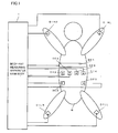
- a body fat measuring apparatus is configured to include a body fat measuring apparatus main body 1 and a plurality of electrodes connected to the body fat measuring apparatus main body 1.
- the plurality of electrodes include a right-hand electric-current electrode DIHR, a left-hand electric-current electrode DIHL, a right-leg electric-current electrode DILR, a left-leg electric-current electrode DILL, an annular-shaped voltage electrode DE1, other voltage electrodes DE2, DE3, DE4 and DE5 and other electric-current electrodes DI3 and DI4.
- right-hand electric-current electrode DIHR left-hand electric-current electrode DIHL, right-leg electric-current electrode DILR, and left-leg electric-current electrode DILL are dot-shaped electrodes which are connected to the respective hands and legs distantly from an abdominal portion which is a portion to be measured.
- Voltage electrode DE1 is an annular-shaped electrode and is placed around a portion above the abdominal portion.
- Voltage electrodes DE2 and DE3 are dot-shaped electrodes and are placed at a right lumbar portion and a left lumbar portion (pit of the stomach, haunch bones) below the abdominal portion, distantly from annular-shaped voltage electrode DE1.
- Dot-shaped electric-current electrodes DI3 and DI4 are laterally placed along a straight line on the abdominal portion (umbilicus position) between annular-shaped voltage electrode DE1 and voltage electrodes DE2 and DE3 such that they are spaced apart by a small interval from each other to sandwich dot-shaped voltage electrodes DE4 and DE5.
- body fat measuring apparatus main body 1 includes a measurement-subject information input part 11, an arithmetic and control part 12, a constant-current generation part 13, a voltage detection part 14, an electrode switching part 15 and a display part 16.
- measurement-subject information input part 11 includes a measurement start button 22, a measurement stop button 23 and ten keys 24 which enable inputting, for example, a height, a weight and a perimeter length at the umbilicus position of the measurement subject.
- Arithmetic and control part 12 executes an arithmetic and controls such as switching among the electrodes, measurements of bioelectrical impedances and calculations of body fat, in accordance with incorporated programs, depending on the progress of measurements.
- Constant-current generation part 13 generates a high-frequency constant current to energize the living body through two electric-current electrodes.
- Voltage detection part 14 detects the voltage between two voltage electrodes which are placed between the two electric-current electrodes being energized. The bioelectrical impedance between the voltage electrodes can be calculated from the voltage detected by the voltage detection part 14 and the value of the constant electric-current for the energization.
- Electrode switching part 15 includes a plurality of switches SW1a, SW1b, ... and SW4 and switches, among these electrodes, the electrodes connected to constant-current generation part 13 and voltage detection part 14, under the control of arithmetic and control part 12.
- the common terminals of a switch SW2a and a switch SW2b are connected to one end and the other end of the output terminal of constant-current generation part 13.
- the common terminal of a switch SW3a is connected to one end of the input of voltage detection part 14 while the common terminals of switches SW3b and SW3c are connected to the other end of the input of voltage detection part 14.
- Right-hand electric-current electrode DIHR is connected to an "a" terminal of switch SW2a while right-leg electric-current electrode DILR is connected to an "a" terminal of switch SW2b.
- Left-hand electric-current electrode DIHL is connected to right-hand electric-current electrode DIHR through switch SW1a while left-leg electric-current electrode DILL is connected to right-leg electric-current electrode DILR through switch SW1b.
- Electric-current electrode DI3 and electric-current electrode DI4 are connected to a "b" terminal of switch SW2a and a “b” terminal of switch SW2b, respectively.
- the "a" terminals of switch SW3a and switch SW3b are connected to annular-shaped voltage electrode DE1, a "b" terminal of switch SW3a is connected to voltage electrode DE4 and a “b” terminal of switch SW3b is connected to voltage electrode DE5.
- Voltage electrode DE2 is connected to an "a" terminal of switch SW3c through an “a” terminal of switch SW4, and voltage electrode DE3 is connected to the "a" terminal of switch SW3c through a "b" terminal of switch SW4.
- the "b" terminal of switch SW3c is opened.
- display part 16 includes a physique-characteristics display part 16a for displaying physique characteristics such as the height, the weight and the perimeter length at the umbilicus position of the measurement subject (patient) which have been input, and a measurement display part 16b for displaying the results of measurements such as a body fat area, a visceral fat area, and a subcutaneous fat area.
- physique-characteristics display part 16a for displaying physique characteristics such as the height, the weight and the perimeter length at the umbilicus position of the measurement subject (patient) which have been input
- a measurement display part 16b for displaying the results of measurements such as a body fat area, a visceral fat area, and a subcutaneous fat area.
- step ST1 measurement-subject information input part 11 receives characteristic values reflecting the size of the measurement-subject body such as the weight, the height and the perimeter length at the umbilicus position and stores them in the storage part of arithmetic and control part 12. Subsequently, the process proceeds to step ST3.
- step ST3 manipulation of measurement starting button 22 performed by the measurement subject is received. Then, the process proceeds to step ST4.
- step ST4 it is determined whether or not the input physique information falls within a pre-stored normal range. In the event that it does not fall within the normal range such as when it includes an extremely abnormal value, the process proceeds to step ST9 where errors are displayed. On the other hand, when it falls within the normal range, the process proceeds to step ST5.
- step ST5 a process using electrode setting 1 is executed. More specifically, switch SW1a and switch SW1b are turned on, thus short-circuiting right-hand electric-current electrode DIHR and left-hand electric-current electrode DIHL, while short-circuiting right-leg electric-current electrode DILR and left-leg electric-current electrode DILL. Further, switches SW2a, SW2b and SW3a are turned to their "a" terminals and switches SW3c and SW4 are also turned to their "a” terminals. Consequently, constant-current generation part 13 is connected between hand electric-current electrodes DIHR, DIHL and leg electric-current electrodes DILR, DILL while annular-shaped voltage electrode DE1 and right-lumbar voltage electrode DE2 are connected to voltage detection part 14.
- step ST6 it is determined whether or not the impedance value has fallen in a predetermined range, within a predetermined time. If the impedance value has not fallen in the predetermined range within the predetermined time, it is determined that proper measurement has not been performed, and thus the process proceeds to step ST10 where errors are displayed. On the other hand, when the impedance value has fallen in the predetermined range, it is determined that proper measurement has been progressed, and the process proceeds to step ST7.
- step ST7 it is determined whether or not the impedance value has been stabilized within a predetermine time.
- the process proceeds to step ST 11 where errors are displayed.
- step ST8 the impedance Zright between annular-shaped voltage electrode DE1 and right-lumbar voltage electrode DE2 is determined and stored in the storage part of arithmetic and control part 12. Subsequently, the process proceeds to step ST12.
- step ST12 a process using electrode setting 2 is executed. More specifically, switch SW1a and switch SW1b are turned on, thus short-circuiting right-hand electric-current electrode DIHR and left-hand electric-current electrode DIHL, while short-circuiting right-leg electric-current electrode DILR and left-leg electric-current electrode DILL. Further, switches SW2a, SW2b and SW3a are turned to their “a” terminals while switch SW3c is turned to its "a” terminal and switch SW4 is turned to its "b” terminal.
- constant-current generation part 13 is connected between the hand electric-current electrodes DIHR, DIHL and the leg electric-current electrodes DILR, DILL while annular-shaped voltage electrode DE1 and the left-lumbar voltage electrode DE3 are connected to voltage detection part 14.
- a constant electric current is flowed between hand electric-current electrodes DIHR, DIHL and leg electric-current electrodes DILR, DILL while voltage detection part 14 detects the voltage between annular-shaped voltage electrode DE1 and left-lumber voltage electrode DE3 and the bioelectrical impedance of the abdominal portion is calculated.
- the process proceeds to step ST13.
- step ST13 it is determined whether or not the impedance value has fallen in a predetermined range, within a predetermined time. If the impedance value has not fallen in the predetermined range within the predetermined time, it is determined that proper measurement has not been performed, and the process proceeds to step ST16 where errors are displayed. On the other hand, when the impedance value has fallen in the predetermined range, it is determined that proper measurement has been progressed and the process proceeds to step ST14.
- step ST14 it is determined whether or not the impedance value has been stabilized within a predetermine time. When it has not been stabilized, the process proceeds to step ST17 where errors are displayed. On the other hand, when the impedance has been stabilized, the process proceeds to step ST15. In step ST15, an impedance Zleft between annular-shaped voltage electrode DE1 and left-lumbar voltage electrode DE3 is determined and stored in the storage part of arithmetic and control part 12. Subsequently, the process proceeds to step ST18.
- step ST18 a process using electrode setting 3 is executed.
- the electric-current electrodes at an abdominal portion 1 and an abdominal portion 4 and the voltage electrodes at an abdominal portion 2 and an abdominal portion 3 are selected. More specifically, switch SW2a and switch SW2b are turned to their "b" terminals while switches SW3a, SW3b and SW3c are turned to their "b” terminals. Consequently, constant-current generation part 13 is connected between electric-current electrodes DI3 and DI4 on the abdominal portion, while voltage electrodes DE4 and DE5 on the abdominal portion are connected to voltage detection part 14.
- step ST19 it is determined whether or not the impedance value has fallen in a predetermined range within a predetermined time. If the impedance value has not fallen in the predetermined range within the predetermined time, it is determined that proper measurement has not been performed and the process proceeds to step ST24 where errors are displayed. On the other hand, when the impedance value has fallen in the predetermined range, it is determined that proper measurement has been progressed and, then, the process proceeds to step ST20.
- step ST23 the body fat area, the visceral fat area and the subcutaneous fat area are displayed on display part 16.
- Fig. 3 illustrates exemplary display. Although the body fat is determined and displayed as an area in this case, the body fat volume, the visceral-fat volume and the subcutaneous-fat volume may be determined and displayed.
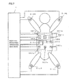
- a body fat measuring apparatus may be configured to include electrodes illustrated in Fig. 7 and employ the electrode placement illustrated therein.
- right-hand electric-current electrode DIHR, left-hand electric-current electrode DIHL, right-leg electric-current electrode DILR and left-leg electric-current electrode DILL are similar to those of Fig. 1.
- Three dot-shaped voltage electrodes DE1a, DE1b and DE1c are placed at the same position as that of annular-shaped voltage electrode DE1 of Fig. 1 such that they are horizontally spaced apart from one another.
- three voltage electrodes DE2a, DE2b and DE2c are placed at positions on the lumbar at the same height as that of the left and light lumbar voltage electrodes DE2 and DE3 of Fig. 1.
- Electric-current voltages DI3, DI4 and voltage electrodes DE4, DE5 placed on the abdominal portion are similar to those of Fig. 1.
- a constant electric current is flowed between right-hand electric-current electrode DIHR and left-hand electric-current electrode DIHL which are being short-circuited and right-leg electric-current electrode DILR and left-leg electric-current electrode DILL which are being short-circuited. Further, the voltages between voltage electrodes DE1a and DE2a, between voltage electrodes DE1b and DE2b and between voltage electrodes DE1c and DE2c are individually detected. Thus, the respective impedances are determined and averaged and, then, the body fat area (volume) at the abdominal portion including subcutaneous fat and visceral fat is determined.
- a body fat measuring apparatus may be configured to include electrodes illustrated in Fig. 8 and have the electrode placement illustrated therein.
- right-hand electric-current electrode DIHR, left-hand electric-current electrode DIHL, right-leg electric-current electrode DILR and left-leg electric-current electrode DILL are similar to those of Fig. 1.
- This embodiment is different from Figs. 1 and 7 in that an annular-shaped electrode DE2 is horizontally placed at the same position as those of voltage electrode DE2 placed on the right lumbar and voltage electrode DE3 placed on the left lumbar in Fig. 1.
- Annular-shaped voltage electrode DE1 provided above the abdominal portion, electric-current electrodes DI3 and DI4 and voltage electrodes DE4 and DE5 which are placed on the abdominal portion are similar to those of Fig. 1.
- a constant electric current is flowed between right-hand electric-current electrode DIHR and left-hand electric-current electrode DIHL which are being short-circuited and right-leg electric-current electrode DILR and left-leg electric-current electrode DILL which are being short-circuited.
- the voltage between annular-shaped voltage electrode DE1 and annular-shaped voltage electrode DE2 is detected and the total impedance of the abdominal portion is determined.
- the body fat area (volume) of the abdominal portion including subcutaneous fat and visceral fat is determined.
- electric-current electrodes for measurement of the abdominal portion are placed at positions separate from the abdominal portion and an annular-shaped voltage electrode or a plurality of voltage electrodes for measurement of the abdominal portion are placed on the abdominal portion to determine the impedance of the abdominal portion, which enables averaging the electric-potential distribution generated over the surface to suppress the variation of the electric-potential distribution due to the distribution of fat within the abdominal portion, thus enabling accurate measurement of fat in the abdominal portion.
- electric-current electrodes and voltage electrodes for measurements in the vicinity of the abdominal subcutaneous region are placed within a sufficiently small distance to determine the impedance of only the subcutaneous fat, which enables determining the influence of the fat in the vicinity of the abdominal subcutaneous region. This enables accurately measuring visceral fat, from the impedance of the abdominal portion, the impedance of abdominal subcutaneous fat, the height, the weight and the abdominal perimeter length of the measurement subject.
Landscapes
- Health & Medical Sciences (AREA)
- Life Sciences & Earth Sciences (AREA)
- Biomedical Technology (AREA)
- Heart & Thoracic Surgery (AREA)
- Veterinary Medicine (AREA)
- Biophysics (AREA)
- Pathology (AREA)
- Engineering & Computer Science (AREA)
- Public Health (AREA)
- Physics & Mathematics (AREA)
- Medical Informatics (AREA)
- Molecular Biology (AREA)
- Surgery (AREA)
- Animal Behavior & Ethology (AREA)
- General Health & Medical Sciences (AREA)
- Nuclear Medicine, Radiotherapy & Molecular Imaging (AREA)
- Radiology & Medical Imaging (AREA)
- Measurement And Recording Of Electrical Phenomena And Electrical Characteristics Of The Living Body (AREA)
Abstract
Description
- The present invention relates to a body fat measuring apparatus, in particular, a body fat measuring apparatus capable of measuring visceral fat with high accuracy.
- As a method for measuring visceral fat, in recent years, there has been known a method for capturing an abdominal cross-sectional image using an X-ray CT, an MRI and the like and determining an area of a fat region occupying the cross-sectional image. Further, as another method, there has been disclosed a method which places a pair of electric-current electrodes on a back portion and an umbilical portion of an abdominal portion, places a pair of detection voltage electrodes on both flank portions, determines a bioelectrical impedance of the abdominal portion from the detected voltage between the voltage electrodes during energization between the electric-current electrodes and determines visceral fat from the bioelectrical impedance (refer to, for example,
Japanese Patent Laying-Open Nos. 2001-252257 2002-369806 US Patent No. 5,335,667 ). - Out of the aforementioned visceral-fat measuring methods, the method using an abdominal cross-sectional image taken through an X-ray CT or an MRI has a problem that it involves a large-size apparatus and therefore measurements of visceral fat can be performed only in medical institutions equipped with such facilities and can not be readily conducted everywhere.
- Further the visceral fat measuring methods disclosed in the aforementioned two publications and the aforementioned literature are predicated on the fact that visceral fat exists as a lump at the center of the abdominal portion, as a measurement principle. However, visceral fat is stuck on the mesenterium in an actual human body and is distributed to some degrees, rather than exists as a lump. Therefore, these methods have the problem of inaccuracy of measurements.
- Furthermore, although visceral fat can be measured through two-point measurements at parts with simple-shaped tissue like four limbs as described in the USP, the impedance of the abdominal portion is affected by the distribution of subcutaneous fat and internal fat, which makes it impossible to accurately measure visceral fat only thorough two-point measurement.
- The present invention has been made in view of the aforementioned problems and aims to provide a body fat measuring apparatus capable of measuring visceral fat with higher accuracy than conventional body fat measuring apparatuses.
- In order to attain the aforementioned object, a body fat measuring apparatus according to the present invention includes: first plural electric-current electrodes placed at positions apart from an abdominal portion of a measurement subject; first plural voltage electrodes placed on the abdominal portion of the measurement subject; second plural electric-current electrodes placed on the abdominal portion of the measurement subject such that they are spaced apart from one another by an interval sufficiently smaller than a perimeter length of the abdominal portion; second plural voltage electrodes placed on the abdominal portion of the measurement subject such that they are spaced apart from one another by an interval sufficiently smaller than the perimeter length of the abdominal portion; and a measurement control part for controlling a measuring operation of the body fat measuring apparatus. Herein, the measurement control part includes: a measurement part which causes an electric current to flow through the first electric-current electrodes and measures the impedance of a first abdominal portion from the electric-potential difference between the first voltage electrodes; a measurement part which causes an electric current to flow through the second electric-current electrodes and measures the impedance of a second abdominal portion from the electric-potential difference between the second voltage electrodes; and a body fat calculation part which calculates the body fat of the measurement subject, from the impedance of the first abdominal portion, the impedance of the second abdominal portion and characteristic values reflecting the size of the measurement subject.
- In the body fat measuring apparatus according to the present invention, desirably, the first plural voltage electrodes include at least one annular-shaped electrode.
- In the body fat measuring apparatus according to the present invention, desirably, the impedance of the first abdominal portion has plural measured values, and the measurement control part further includes an impedance calculation part which calculates the average of the plural measured values and sets the average value as the impedance of the first abdominal portion.
- In the body fat measuring apparatus according to the present invention, desirably, the impedance of the second abdominal portion has plural measured values, and the measurement control part further includes an impedance calculation part which calculates the average of the plural measured values and sets the average value as the impedance of the second abdominal portion.
- In the body fat measuring apparatus according to the present invention, preferably, the first plural electric-current electrodes are placed on four limbs.
- In the body fat measuring apparatus according to the present invention, desirably, the second plural electric-current electrodes and the second plural voltage electrodes are placed at a height in the vicinity of an umbilicus position of the measurement subject.
- In the body fat measuring apparatus according to the present invention, desirably, the characteristic values reflecting the size of the measurement subject include at least one of the height, the weight and the abdominal-portion perimeter length of the measuring subject.
- In the body fat measuring apparatus according to the present invention, desirably, the body fat of the measurement subject includes at least one of a body fat area, a body fat volume, a subcutaneous fat area, a subcutaneous fat volume, a visceral fat area and a visceral fat volume.
- The body fat measuring apparatus according to the present invention may further include a display part which displays the body fat of the measuring subject.
- The foregoing and other objects, features, aspects and advantages of the present invention will become more apparent from the following detailed description of the present invention when taken in conjunction with the accompanying drawings.
-
- Fig. 1 illustrates a general outline of a body fat measuring apparatus according to an embodiment of the present invention.
- Fig. 2 is a circuit diagram illustrating a circuit structure of the body fat measuring apparatus.
- Fig. 3 illustrates an operation part and a display part of the body fat measuring apparatus.
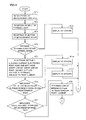
- Figs. 4 to 6 are flow charts describing a measuring process operation of the body fat measuring apparatus according to the same embodiment.
- Fig. 7 illustrates a general outline of a body fat measuring apparatus according to another embodiment of the present invention.
- Fig. 8 illustrates a general outline of a body fat measuring apparatus according to still another embodiment of the present invention.
- Hereinafter, the present invention will be described in more detail with respect to embodiments thereof.
- Referring to Fig. 1, a body fat measuring apparatus according to an embodiment is configured to include a body fat measuring apparatus
main body 1 and a plurality of electrodes connected to the body fat measuring apparatusmain body 1. The plurality of electrodes include a right-hand electric-current electrode DIHR, a left-hand electric-current electrode DIHL, a right-leg electric-current electrode DILR, a left-leg electric-current electrode DILL, an annular-shaped voltage electrode DE1, other voltage electrodes DE2, DE3, DE4 and DE5 and other electric-current electrodes DI3 and DI4. - When the body fat measuring apparatus according to this embodiment is used for measuring visceral fat, right-hand electric-current electrode DIHR, left-hand electric-current electrode DIHL, right-leg electric-current electrode DILR, and left-leg electric-current electrode DILL are dot-shaped electrodes which are connected to the respective hands and legs distantly from an abdominal portion which is a portion to be measured. Voltage electrode DE1 is an annular-shaped electrode and is placed around a portion above the abdominal portion. Voltage electrodes DE2 and DE3 are dot-shaped electrodes and are placed at a right lumbar portion and a left lumbar portion (pit of the stomach, haunch bones) below the abdominal portion, distantly from annular-shaped voltage electrode DE1. Dot-shaped electric-current electrodes DI3 and DI4 are laterally placed along a straight line on the abdominal portion (umbilicus position) between annular-shaped voltage electrode DE1 and voltage electrodes DE2 and DE3 such that they are spaced apart by a small interval from each other to sandwich dot-shaped voltage electrodes DE4 and DE5.
- Referring to Fig. 2, body fat measuring apparatus
main body 1 includes a measurement-subjectinformation input part 11, an arithmetic and control part 12, a constant-current generation part 13, avoltage detection part 14, an electrode switching part 15 and adisplay part 16. - As illustrated in Fig. 3, measurement-subject
information input part 11 includes ameasurement start button 22, ameasurement stop button 23 and tenkeys 24 which enable inputting, for example, a height, a weight and a perimeter length at the umbilicus position of the measurement subject. Arithmetic and control part 12 executes an arithmetic and controls such as switching among the electrodes, measurements of bioelectrical impedances and calculations of body fat, in accordance with incorporated programs, depending on the progress of measurements. Constant-current generation part 13 generates a high-frequency constant current to energize the living body through two electric-current electrodes.Voltage detection part 14 detects the voltage between two voltage electrodes which are placed between the two electric-current electrodes being energized. The bioelectrical impedance between the voltage electrodes can be calculated from the voltage detected by thevoltage detection part 14 and the value of the constant electric-current for the energization. - Electrode switching part 15 includes a plurality of switches SW1a, SW1b, ... and SW4 and switches, among these electrodes, the electrodes connected to constant-current generation part 13 and
voltage detection part 14, under the control of arithmetic and control part 12. The common terminals of a switch SW2a and a switch SW2b are connected to one end and the other end of the output terminal of constant-current generation part 13. Further, the common terminal of a switch SW3a is connected to one end of the input ofvoltage detection part 14 while the common terminals of switches SW3b and SW3c are connected to the other end of the input ofvoltage detection part 14. Right-hand electric-current electrode DIHR is connected to an "a" terminal of switch SW2a while right-leg electric-current electrode DILR is connected to an "a" terminal of switch SW2b. Left-hand electric-current electrode DIHL is connected to right-hand electric-current electrode DIHR through switch SW1a while left-leg electric-current electrode DILL is connected to right-leg electric-current electrode DILR through switch SW1b. - Electric-current electrode DI3 and electric-current electrode DI4 are connected to a "b" terminal of switch SW2a and a "b" terminal of switch SW2b, respectively. The "a" terminals of switch SW3a and switch SW3b are connected to annular-shaped voltage electrode DE1, a "b" terminal of switch SW3a is connected to voltage electrode DE4 and a "b" terminal of switch SW3b is connected to voltage electrode DE5.
- Voltage electrode DE2 is connected to an "a" terminal of switch SW3c through an "a" terminal of switch SW4, and voltage electrode DE3 is connected to the "a" terminal of switch SW3c through a "b" terminal of switch SW4. The "b" terminal of switch SW3c is opened.
- Referring to Fig. 3,
display part 16 includes a physique-characteristics display part 16a for displaying physique characteristics such as the height, the weight and the perimeter length at the umbilicus position of the measurement subject (patient) which have been input, and ameasurement display part 16b for displaying the results of measurements such as a body fat area, a visceral fat area, and a subcutaneous fat area. - Next, there will be described a body fat measuring process executed by the body fat measuring apparatus according to this embodiment, with reference to flow charts illustrated in Figs. 4 to 6. When a power-
supply button 21 is turned on to start the operation, initialization of the measurement circuits such as clearing of a storage part in arithmetic and control part is executed in step ST1. Then, the process proceeds to step ST2. In step ST2, measurement-subjectinformation input part 11 receives characteristic values reflecting the size of the measurement-subject body such as the weight, the height and the perimeter length at the umbilicus position and stores them in the storage part of arithmetic and control part 12. Subsequently, the process proceeds to step ST3. - In step ST3, manipulation of
measurement starting button 22 performed by the measurement subject is received. Then, the process proceeds to step ST4. In step ST4, it is determined whether or not the input physique information falls within a pre-stored normal range. In the event that it does not fall within the normal range such as when it includes an extremely abnormal value, the process proceeds to step ST9 where errors are displayed. On the other hand, when it falls within the normal range, the process proceeds to step ST5. - In step ST5, a process using electrode setting 1 is executed. More specifically, switch SW1a and switch SW1b are turned on, thus short-circuiting right-hand electric-current electrode DIHR and left-hand electric-current electrode DIHL, while short-circuiting right-leg electric-current electrode DILR and left-leg electric-current electrode DILL. Further, switches SW2a, SW2b and SW3a are turned to their "a" terminals and switches SW3c and SW4 are also turned to their "a" terminals. Consequently, constant-current generation part 13 is connected between hand electric-current electrodes DIHR, DIHL and leg electric-current electrodes DILR, DILL while annular-shaped voltage electrode DE1 and right-lumbar voltage electrode DE2 are connected to
voltage detection part 14. Thus, a constant electric current is flowed between hand electric-current electrodes DIHR, DIHL and leg electric-current electrodes DILR, DILL, whilevoltage detection part 14 detects the voltage between annular-shaped voltage electrode DE1 and right-lumber voltage electrode DE2 and a bioelectrical impedance of the abdominal portion is calculated. Next, the process proceeds to step ST6. - In step ST6, it is determined whether or not the impedance value has fallen in a predetermined range, within a predetermined time. If the impedance value has not fallen in the predetermined range within the predetermined time, it is determined that proper measurement has not been performed, and thus the process proceeds to step ST10 where errors are displayed. On the other hand, when the impedance value has fallen in the predetermined range, it is determined that proper measurement has been progressed, and the process proceeds to step ST7.
- In step ST7, it is determined whether or not the impedance value has been stabilized within a predetermine time. When the impedance has not been stabilized, the process proceeds to step
ST 11 where errors are displayed. On the other hand, when the impedance has been stabilized, the process proceeds to step ST8. In step ST8, the impedance Zright between annular-shaped voltage electrode DE1 and right-lumbar voltage electrode DE2 is determined and stored in the storage part of arithmetic and control part 12. Subsequently, the process proceeds to step ST12. - In step ST12, a process using electrode setting 2 is executed. More specifically, switch SW1a and switch SW1b are turned on, thus short-circuiting right-hand electric-current electrode DIHR and left-hand electric-current electrode DIHL, while short-circuiting right-leg electric-current electrode DILR and left-leg electric-current electrode DILL. Further, switches SW2a, SW2b and SW3a are turned to their "a" terminals while switch SW3c is turned to its "a" terminal and switch SW4 is turned to its "b" terminal. Consequently, constant-current generation part 13 is connected between the hand electric-current electrodes DIHR, DIHL and the leg electric-current electrodes DILR, DILL while annular-shaped voltage electrode DE1 and the left-lumbar voltage electrode DE3 are connected to
voltage detection part 14. Thus, a constant electric current is flowed between hand electric-current electrodes DIHR, DIHL and leg electric-current electrodes DILR, DILL whilevoltage detection part 14 detects the voltage between annular-shaped voltage electrode DE1 and left-lumber voltage electrode DE3 and the bioelectrical impedance of the abdominal portion is calculated. Next, the process proceeds to step ST13. - In step ST13, it is determined whether or not the impedance value has fallen in a predetermined range, within a predetermined time. If the impedance value has not fallen in the predetermined range within the predetermined time, it is determined that proper measurement has not been performed, and the process proceeds to step ST16 where errors are displayed. On the other hand, when the impedance value has fallen in the predetermined range, it is determined that proper measurement has been progressed and the process proceeds to step ST14.
- In step ST14, it is determined whether or not the impedance value has been stabilized within a predetermine time. When it has not been stabilized, the process proceeds to step ST17 where errors are displayed. On the other hand, when the impedance has been stabilized, the process proceeds to step ST15. In step ST15, an impedance Zleft between annular-shaped voltage electrode DE1 and left-lumbar voltage electrode DE3 is determined and stored in the storage part of arithmetic and control part 12. Subsequently, the process proceeds to step ST18.
- In step ST18, a process using electrode setting 3 is executed. Herein, the electric-current electrodes at an
abdominal portion 1 and anabdominal portion 4 and the voltage electrodes at anabdominal portion 2 and anabdominal portion 3 are selected. More specifically, switch SW2a and switch SW2b are turned to their "b" terminals while switches SW3a, SW3b and SW3c are turned to their "b" terminals. Consequently, constant-current generation part 13 is connected between electric-current electrodes DI3 and DI4 on the abdominal portion, while voltage electrodes DE4 and DE5 on the abdominal portion are connected tovoltage detection part 14. Thus, a constant electric current is flowed between electric-current electrodes DI3 and DI4 on the abdominal portion whilevoltage detection part 14 detects the voltage between voltage electrodes DE4 and DE5 on the abdominal portion and, then, the bioelectrical subcutaneous impedance in the vicinity of the abdominal portion is calculated. Next, the process proceeds to step ST19. - In step ST19, it is determined whether or not the impedance value has fallen in a predetermined range within a predetermined time. If the impedance value has not fallen in the predetermined range within the predetermined time, it is determined that proper measurement has not been performed and the process proceeds to step ST24 where errors are displayed. On the other hand, when the impedance value has fallen in the predetermined range, it is determined that proper measurement has been progressed and, then, the process proceeds to step ST20.
- In step ST20, it is determined whether or not the impedance value has been stabilized within a predetermine time. When it has not been stabilized, the process proceeds to step ST25 where errors are displayed. On the other hand, when the impedance has been stabilized, the process proceeds to step ST21. In step ST21, an impedance Zs in the vicinity of the abdominal portion is determined. Subsequently, the process proceeds to step ST22. In step ST22, the following equations are computed in an arithmetic and control part 12 to determine a visceral-fat area, a body fat area and a subcutaneous fat area.


wherein - Zbody: the average of impedance Zright between the annular-shaped electrode and the right-lumbar electrode and impedance Zleft between the annular-shaped electrode and the left-lumbar electrodes
- R: the length of the waist
- S: the area of a circle having a perimeter length equal to the length of waist
- L: the vertical distance between the annular-shaped electrode and the left and right lumber electrodes
- A, B, C, D, E, F and G: coefficients
- Next, the process proceeds to step
ST 23. In step ST23, the body fat area, the visceral fat area and the subcutaneous fat area are displayed ondisplay part 16. Fig. 3 illustrates exemplary display. Although the body fat is determined and displayed as an area in this case, the body fat volume, the visceral-fat volume and the subcutaneous-fat volume may be determined and displayed. - As another embodiment of the present invention, a body fat measuring apparatus may be configured to include electrodes illustrated in Fig. 7 and employ the electrode placement illustrated therein. In this embodiment, right-hand electric-current electrode DIHR, left-hand electric-current electrode DIHL, right-leg electric-current electrode DILR and left-leg electric-current electrode DILL are similar to those of Fig. 1. Three dot-shaped voltage electrodes DE1a, DE1b and DE1c are placed at the same position as that of annular-shaped voltage electrode DE1 of Fig. 1 such that they are horizontally spaced apart from one another. Further, three voltage electrodes DE2a, DE2b and DE2c are placed at positions on the lumbar at the same height as that of the left and light lumbar voltage electrodes DE2 and DE3 of Fig. 1. Electric-current voltages DI3, DI4 and voltage electrodes DE4, DE5 placed on the abdominal portion are similar to those of Fig. 1.
- With the body fat measuring apparatus according to this embodiment, a constant electric current is flowed between right-hand electric-current electrode DIHR and left-hand electric-current electrode DIHL which are being short-circuited and right-leg electric-current electrode DILR and left-leg electric-current electrode DILL which are being short-circuited. Further, the voltages between voltage electrodes DE1a and DE2a, between voltage electrodes DE1b and DE2b and between voltage electrodes DE1c and DE2c are individually detected. Thus, the respective impedances are determined and averaged and, then, the body fat area (volume) at the abdominal portion including subcutaneous fat and visceral fat is determined.
- As still another embodiment of the present invention, a body fat measuring apparatus may be configured to include electrodes illustrated in Fig. 8 and have the electrode placement illustrated therein. In this embodiment, right-hand electric-current electrode DIHR, left-hand electric-current electrode DIHL, right-leg electric-current electrode DILR and left-leg electric-current electrode DILL are similar to those of Fig. 1. This embodiment is different from Figs. 1 and 7 in that an annular-shaped electrode DE2 is horizontally placed at the same position as those of voltage electrode DE2 placed on the right lumbar and voltage electrode DE3 placed on the left lumbar in Fig. 1. Annular-shaped voltage electrode DE1 provided above the abdominal portion, electric-current electrodes DI3 and DI4 and voltage electrodes DE4 and DE5 which are placed on the abdominal portion are similar to those of Fig. 1.
- With the body fat measuring apparatus according to this embodiment, a constant electric current is flowed between right-hand electric-current electrode DIHR and left-hand electric-current electrode DIHL which are being short-circuited and right-leg electric-current electrode DILR and left-leg electric-current electrode DILL which are being short-circuited. Then, the voltage between annular-shaped voltage electrode DE1 and annular-shaped voltage electrode DE2 is detected and the total impedance of the abdominal portion is determined. Thus, the body fat area (volume) of the abdominal portion including subcutaneous fat and visceral fat is determined.
- With the present invention, electric-current electrodes for measurement of the abdominal portion are placed at positions separate from the abdominal portion and an annular-shaped voltage electrode or a plurality of voltage electrodes for measurement of the abdominal portion are placed on the abdominal portion to determine the impedance of the abdominal portion, which enables averaging the electric-potential distribution generated over the surface to suppress the variation of the electric-potential distribution due to the distribution of fat within the abdominal portion, thus enabling accurate measurement of fat in the abdominal portion. Further, electric-current electrodes and voltage electrodes for measurements in the vicinity of the abdominal subcutaneous region are placed within a sufficiently small distance to determine the impedance of only the subcutaneous fat, which enables determining the influence of the fat in the vicinity of the abdominal subcutaneous region. This enables accurately measuring visceral fat, from the impedance of the abdominal portion, the impedance of abdominal subcutaneous fat, the height, the weight and the abdominal perimeter length of the measurement subject.
- Although the present invention has been described and illustrated in detail, it is clearly understood that the same is by way of illustration and example only and is not to be taken by way of limitation, the spirit and scope of the present invention being limited only by the terms of the appended claims.
Claims (9)
- A body fat measuring apparatus comprising:first plural electric-current electrodes (DIHR, DIHL, DILR, DILL) placed at positions apart from an abdominal portion of a measurement subject;first plural voltage electrodes (DE1, DE2, DE3) placed on said abdominal portion of said measurement subject;second plural electric-current electrodes (DI3, DI4) placed on said abdominal portion of said measurement subject such that they are spaced apart from one another by an interval sufficiently smaller than a perimeter length of said abdominal portion;second plural voltage electrodes (DE4, DE5) placed on said abdominal portion such that they are spaced apart from one another by an interval sufficiently smaller than said perimeter length of said abdominal portion; anda measurement control part (12) for controlling a measuring operation of said body fat measuring apparatus, whereinsaid measurement control part (12) includes:a first measurement part (ST8, ST15) which causes an electric current to flow through said first plural electric-current electrodes and measures the impedance of a first abdominal portion from the electric-potential difference between said first plural voltage electrodes;a second measurement part (ST21) which causes an electric current to flow through said second plural electric-current electrodes and measures the impedance of a second abdominal portion from the electric-potential difference between said second plural voltage electrodes; anda body fat calculation part (ST22) which calculates the body fat of said measurement subject, from said impedance of said first abdominal portion, said impedance of said second abdominal portion and a characteristic value reflecting the size of the measurement subject.
- The body fat measuring apparatus according to claim 1, wherein
said first plural voltage electrodes include at least one annular-shaped electrode. - The body fat measuring apparatus according to claim 1, wherein
said impedance of said first abdominal portion has plural measured values, and
said measurement control part further includes an impedance calculation part (ST8, ST15) which calculates the average of said plural measured values and sets said average value as the impedance of said first abdominal portion. - The body fat measuring apparatus according to claim 1, wherein
said impedance of said second abdominal portion has plural measured values, and
said measurement control part further includes an impedance calculation part (ST21) which calculates the average of said plural measured values and sets said average value as the impedance of said second abdominal portion. - The body fat measuring apparatus according to claim 1, wherein
said first plural electric-current electrodes are placed on four limbs. - The body fat measuring apparatus according to claim 1, wherein
said second plural electric-current electrodes and said second plural voltage electrodes are placed at a height in the vicinity of an umbilicus position of said measurement subject. - The body fat measuring apparatus according to claim 1, wherein
said characteristic value reflecting the size of said measurement subject includes at least one of the height, the weight and the abdominal-portion perimeter length of said measuring subject. - The body fat measuring apparatus according to claim 1, wherein
said body fat of said measurement subject includes at least one of a body fat area, a body fat volume, a subcutaneous fat area, a subcutaneous fat volume, a visceral fat area and a visceral fat volume. - The body fat measuring apparatus according to claim 1, further comprising:a display part (16) which displays said body fat of said measuring subject.
Applications Claiming Priority (1)
| Application Number | Priority Date | Filing Date | Title |
|---|---|---|---|
| JP2005096686A JP4645266B2 (en) | 2005-03-30 | 2005-03-30 | Body fat measuring device |
Publications (2)
| Publication Number | Publication Date |
|---|---|
| EP1707117A1 true EP1707117A1 (en) | 2006-10-04 |
| EP1707117B1 EP1707117B1 (en) | 2010-05-19 |
Family
ID=36650902
Family Applications (1)
| Application Number | Title | Priority Date | Filing Date |
|---|---|---|---|
| EP06006155A Expired - Lifetime EP1707117B1 (en) | 2005-03-30 | 2006-03-24 | Body fat measuring apparatus capable of measuring visceral fat with high accuracy |
Country Status (4)
| Country | Link |
|---|---|
| US (1) | US7813794B2 (en) |
| EP (1) | EP1707117B1 (en) |
| JP (1) | JP4645266B2 (en) |
| DE (1) | DE602006014314D1 (en) |
Cited By (1)
| Publication number | Priority date | Publication date | Assignee | Title |
|---|---|---|---|---|
| EP1958567A4 (en) * | 2005-11-30 | 2011-06-08 | Omron Healthcare Co Ltd | Body fat measuring apparatus capable of easily and accurately measuring amount of visceral fat |
Families Citing this family (27)
| Publication number | Priority date | Publication date | Assignee | Title |
|---|---|---|---|---|
| AUPQ113799A0 (en) | 1999-06-22 | 1999-07-15 | University Of Queensland, The | A method and device for measuring lymphoedema |
| CA2578106C (en) | 2004-06-18 | 2015-09-01 | The University Of Queensland | Oedema detection |
| US8103337B2 (en) | 2004-11-26 | 2012-01-24 | Impedimed Limited | Weighted gradient method and system for diagnosing disease |
| EP1712179B1 (en) * | 2005-04-13 | 2010-12-15 | Tanita Corporation | Trunk visceral fat measuring method and apparatus |
| CA2608962C (en) | 2005-07-01 | 2016-12-06 | Scott Chetham | Monitoring system |
| AU2006265763B2 (en) | 2005-07-01 | 2012-08-09 | Impedimed Limited | Monitoring system |
| EP1912563B1 (en) | 2005-08-02 | 2016-04-20 | Impedimed Limited | Impedance parameter values |
| WO2007041783A1 (en) | 2005-10-11 | 2007-04-19 | Impedance Cardiology Systems, Inc. | Hydration status monitoring |
| JP5431147B2 (en) | 2006-05-30 | 2014-03-05 | インぺディメッド リミテッド | Impedance measurement |
| CA2670293C (en) | 2006-11-30 | 2017-01-03 | Impedimed Limited | Measurement apparatus |
| WO2008086565A1 (en) | 2007-01-15 | 2008-07-24 | Impedimed Limited | Monitoring system |
| JP4905197B2 (en) * | 2007-03-19 | 2012-03-28 | オムロンヘルスケア株式会社 | Visceral fat measuring device |
| US8487686B2 (en) | 2007-03-30 | 2013-07-16 | Impedimed Limited | Active guarding for reduction of resistive and capacitive signal loading with adjustable control of compensation level |
| EP2148613B9 (en) | 2007-04-20 | 2014-12-10 | Impedimed Limited | Monitoring system and probe |
| EP2211714B1 (en) | 2007-11-05 | 2016-11-23 | Impedimed Limited | Impedance determination |
| AU2008207672B2 (en) | 2008-02-15 | 2013-10-31 | Impedimed Limited | Impedance Analysis |
| JP5287079B2 (en) * | 2008-09-22 | 2013-09-11 | オムロンヘルスケア株式会社 | Visceral fat measuring device |
| JP2010069225A (en) * | 2008-09-22 | 2010-04-02 | Omron Healthcare Co Ltd | Visceral fat measuring apparatus |
| EP2348987B1 (en) | 2008-11-28 | 2017-03-22 | Impedimed Limited | Impedance measurement process |
| WO2011050393A1 (en) | 2009-10-26 | 2011-05-05 | Impedimed Limited | Fluid level indicator determination |
| WO2011060497A1 (en) | 2009-11-18 | 2011-05-26 | Impedimed Limited | Signal distribution for patient-electrode measurements |
| KR102335768B1 (en) | 2014-10-21 | 2021-12-06 | 삼성전자주식회사 | Apparatus and method for measuring body fat |
| KR20160094219A (en) * | 2015-01-30 | 2016-08-09 | 삼성전자주식회사 | Apparatus and method for measuring body composition |
| KR102822726B1 (en) * | 2017-01-24 | 2025-06-18 | 삼성전자주식회사 | Apparatus and method for measuring bioelectric impedance, Apparatus and method for measuring biometric information |
| US11083392B2 (en) * | 2017-07-13 | 2021-08-10 | Samsung Electronics Co., Ltd. | Bio-processor, bio-signal detecting system, and operation method of bio-processor |
| CN112294286B (en) * | 2020-11-19 | 2023-04-25 | 西安电子科技大学 | A device for measuring human abdominal impedance |
| WO2024049038A1 (en) | 2022-08-27 | 2024-03-07 | Samsung Electronics Co., Ltd. | Method and system for estimation of the abdominal fat |
Citations (4)
| Publication number | Priority date | Publication date | Assignee | Title |
|---|---|---|---|---|
| JP2001252257A (en) * | 2000-01-07 | 2001-09-18 | Kao Corp | Adipometry and adipometer |
| JP2002369806A (en) * | 2001-04-13 | 2002-12-24 | Kao Corp | Body fat measurement device |
| WO2003105688A1 (en) * | 2002-06-01 | 2003-12-24 | ヤーマン株式会社 | System for displaying quantities of bone, water and/or muscle of body |
| US20040054298A1 (en) * | 2000-12-14 | 2004-03-18 | Yoshihisa Masuo | Body impedance measuring instrument |
Family Cites Families (8)
| Publication number | Priority date | Publication date | Assignee | Title |
|---|---|---|---|---|
| US5335667A (en) * | 1992-11-20 | 1994-08-09 | University Of Utah Research Foundation | Method and apparatus for determining body composition using bioelectrical impedance |
| JPH09285455A (en) * | 1996-02-23 | 1997-11-04 | Omron Corp | Health management guideline advice device |
| JP2001212111A (en) * | 1999-11-25 | 2001-08-07 | Mitsubishi Electric Corp | Visceral fat measuring device |
| JP4840952B2 (en) * | 2000-09-19 | 2011-12-21 | 株式会社フィジオン | Bioelectrical impedance measurement method and measurement device, and health guideline management advice device using the measurement device |
| EP1363531B1 (en) * | 2001-02-22 | 2010-10-20 | Kao Corporation | Apparatus for measuring body fat |
| JP2002291714A (en) * | 2002-03-18 | 2002-10-08 | Tanita Corp | Measurement method and measurement device for adipose |
| JP4099428B2 (en) * | 2003-05-21 | 2008-06-11 | 株式会社タニタ | Muscle mass estimation device |
| JP4788147B2 (en) * | 2005-01-26 | 2011-10-05 | パナソニック電工株式会社 | Body fat measuring device |
-
2005
- 2005-03-30 JP JP2005096686A patent/JP4645266B2/en not_active Expired - Fee Related
-
2006
- 2006-03-24 EP EP06006155A patent/EP1707117B1/en not_active Expired - Lifetime
- 2006-03-24 DE DE602006014314T patent/DE602006014314D1/en not_active Expired - Lifetime
- 2006-03-28 US US11/390,278 patent/US7813794B2/en not_active Expired - Lifetime
Patent Citations (5)
| Publication number | Priority date | Publication date | Assignee | Title |
|---|---|---|---|---|
| JP2001252257A (en) * | 2000-01-07 | 2001-09-18 | Kao Corp | Adipometry and adipometer |
| US20040054298A1 (en) * | 2000-12-14 | 2004-03-18 | Yoshihisa Masuo | Body impedance measuring instrument |
| JP2002369806A (en) * | 2001-04-13 | 2002-12-24 | Kao Corp | Body fat measurement device |
| WO2003105688A1 (en) * | 2002-06-01 | 2003-12-24 | ヤーマン株式会社 | System for displaying quantities of bone, water and/or muscle of body |
| EP1554976A1 (en) * | 2002-06-12 | 2005-07-20 | Ya-Man Ltd | System for displaying quantities of bone, water and/or muscle of body |
Non-Patent Citations (2)
| Title |
|---|
| PATENT ABSTRACTS OF JAPAN vol. 2000, no. 26 1 July 2002 (2002-07-01) * |
| PATENT ABSTRACTS OF JAPAN vol. 2003, no. 04 2 April 2003 (2003-04-02) * |
Cited By (1)
| Publication number | Priority date | Publication date | Assignee | Title |
|---|---|---|---|---|
| EP1958567A4 (en) * | 2005-11-30 | 2011-06-08 | Omron Healthcare Co Ltd | Body fat measuring apparatus capable of easily and accurately measuring amount of visceral fat |
Also Published As
| Publication number | Publication date |
|---|---|
| US20060224080A1 (en) | 2006-10-05 |
| US7813794B2 (en) | 2010-10-12 |
| JP2006271745A (en) | 2006-10-12 |
| EP1707117B1 (en) | 2010-05-19 |
| JP4645266B2 (en) | 2011-03-09 |
| DE602006014314D1 (en) | 2010-07-01 |
Similar Documents
| Publication | Publication Date | Title |
|---|---|---|
| EP1707117B1 (en) | Body fat measuring apparatus capable of measuring visceral fat with high accuracy | |
| Lee et al. | Recent issues on body composition imaging for sarcopenia evaluation | |
| US9259169B2 (en) | Visceral fat measurement device | |
| EP2155058B1 (en) | Indicator | |
| USRE42833E1 (en) | Method and apparatus for measuring distribution of body fat | |
| EP1948017B1 (en) | Hydration status monitoring | |
| US6321112B1 (en) | Device to provide data as a guide to health management | |
| AU757258B2 (en) | Health condition judging/displaying device | |
| JP4848369B2 (en) | Apparatus and method for operating edema detection | |
| Cheung et al. | Freehand three-dimensional ultrasound system for assessment of scoliosis | |
| EP1245186B1 (en) | A device for measuring the amount of intra-abdominal fat during the monitoring of an individual's slimming | |
| EP1967136B1 (en) | Abdominal impedance measurement apparatus and body composition determination apparatus | |
| JP2003525678A (en) | Measuring device for measurement of abnormal load on human body in upright position | |
| EP3015065B1 (en) | Feet positioning system for magnetic resonance imaging studies | |
| JP2000350710A (en) | Method and apparatus for measuring body fat distribution | |
| US8600474B2 (en) | Body fat measurement device | |
| US8670822B2 (en) | Body fat measurement device | |
| Biggs et al. | Electrical resistivity of the upper arm and leg yields good estimates of whole body fat | |
| RU2699727C2 (en) | Method of ultrasonic diagnostics of retroperitoneal visceral obesity | |
| Lee et al. | Usefulness of virtual expiratory CT images to compensate for respiratory liver motion in ultrasound/CT image fusion: a prospective study in patients with focal hepatic lesions | |
| EP1639946B1 (en) | Ultrasonic diagnostic apparatus | |
| AU2014200697B2 (en) | Indicator | |
| Mária Takács et al. | COMPARING ZEBRIS ULTRASOUND-BASED MOTION ANALYSIS SYSTEM WITH X-RAY DURING THE EXAMINATION OF POSTURE AT CHILDREN SUFFERING FROM SCOLIOSIS | |
| JP2002291714A (en) | Measurement method and measurement device for adipose |
Legal Events
| Date | Code | Title | Description |
|---|---|---|---|
| PUAI | Public reference made under article 153(3) epc to a published international application that has entered the european phase |
Free format text: ORIGINAL CODE: 0009012 |
|
| AK | Designated contracting states |
Kind code of ref document: A1 Designated state(s): AT BE BG CH CY CZ DE DK EE ES FI FR GB GR HU IE IS IT LI LT LU LV MC NL PL PT RO SE SI SK TR |
|
| AX | Request for extension of the european patent |
Extension state: AL BA HR MK YU |
|
| 17P | Request for examination filed |
Effective date: 20061010 |
|
| AKX | Designation fees paid |
Designated state(s): DE ES FR GB IT |
|
| 17Q | First examination report despatched |
Effective date: 20080115 |
|
| GRAP | Despatch of communication of intention to grant a patent |
Free format text: ORIGINAL CODE: EPIDOSNIGR1 |
|
| GRAS | Grant fee paid |
Free format text: ORIGINAL CODE: EPIDOSNIGR3 |
|
| RIN1 | Information on inventor provided before grant (corrected) |
Inventor name: SHIGA, TOSHIKAZUC/O OMRON HEALTHCARE CO., LTD. Inventor name: OKU, SHOJIROC/O OMRON HEALTHCARE CO., LTD. Inventor name: OSHIMA, YOSHITAKEC/O OMRON HEALTHCARE CO., LTD. |
|
| GRAA | (expected) grant |
Free format text: ORIGINAL CODE: 0009210 |
|
| AK | Designated contracting states |
Kind code of ref document: B1 Designated state(s): DE ES FR GB IT |
|
| REG | Reference to a national code |
Ref country code: GB Ref legal event code: FG4D |
|
| REF | Corresponds to: |
Ref document number: 602006014314 Country of ref document: DE Date of ref document: 20100701 Kind code of ref document: P |
|
| PG25 | Lapsed in a contracting state [announced via postgrant information from national office to epo] |
Ref country code: ES Free format text: LAPSE BECAUSE OF FAILURE TO SUBMIT A TRANSLATION OF THE DESCRIPTION OR TO PAY THE FEE WITHIN THE PRESCRIBED TIME-LIMIT Effective date: 20100830 |
|
| PLBE | No opposition filed within time limit |
Free format text: ORIGINAL CODE: 0009261 |
|
| STAA | Information on the status of an ep patent application or granted ep patent |
Free format text: STATUS: NO OPPOSITION FILED WITHIN TIME LIMIT |
|
| PG25 | Lapsed in a contracting state [announced via postgrant information from national office to epo] |
Ref country code: IT Free format text: LAPSE BECAUSE OF FAILURE TO SUBMIT A TRANSLATION OF THE DESCRIPTION OR TO PAY THE FEE WITHIN THE PRESCRIBED TIME-LIMIT Effective date: 20100519 |
|
| 26N | No opposition filed |
Effective date: 20110222 |
|
| REG | Reference to a national code |
Ref country code: DE Ref legal event code: R097 Ref document number: 602006014314 Country of ref document: DE Effective date: 20110221 |
|
| GBPC | Gb: european patent ceased through non-payment of renewal fee |
Effective date: 20110324 |
|
| REG | Reference to a national code |
Ref country code: FR Ref legal event code: ST Effective date: 20111130 |
|
| PG25 | Lapsed in a contracting state [announced via postgrant information from national office to epo] |
Ref country code: FR Free format text: LAPSE BECAUSE OF NON-PAYMENT OF DUE FEES Effective date: 20110331 |
|
| PG25 | Lapsed in a contracting state [announced via postgrant information from national office to epo] |
Ref country code: GB Free format text: LAPSE BECAUSE OF NON-PAYMENT OF DUE FEES Effective date: 20110324 |
|
| REG | Reference to a national code |
Ref country code: DE Ref legal event code: R082 Ref document number: 602006014314 Country of ref document: DE Representative=s name: KILIAN KILIAN & PARTNER, DE Ref country code: DE Ref legal event code: R082 Ref document number: 602006014314 Country of ref document: DE Representative=s name: KILIAN KILIAN & PARTNER MBB PATENTANWAELTE, DE |
|
| REG | Reference to a national code |
Ref country code: DE Ref legal event code: R081 Ref document number: 602006014314 Country of ref document: DE Owner name: FUKUDA DENSHI CO. LTD., JP Free format text: FORMER OWNER: OMRON HEALTHCARE CO., LTD., KYOTO-SHI, KYOTO, JP Ref country code: DE Ref legal event code: R082 Ref document number: 602006014314 Country of ref document: DE Representative=s name: KILIAN KILIAN & PARTNER MBB PATENTANWAELTE, DE Ref country code: DE Ref legal event code: R082 Ref document number: 602006014314 Country of ref document: DE Representative=s name: KILIAN KILIAN & PARTNER, DE |
|
| PGFP | Annual fee paid to national office [announced via postgrant information from national office to epo] |
Ref country code: DE Payment date: 20240130 Year of fee payment: 19 |
|
| REG | Reference to a national code |
Ref country code: DE Ref legal event code: R119 Ref document number: 602006014314 Country of ref document: DE |
|
| PG25 | Lapsed in a contracting state [announced via postgrant information from national office to epo] |
Ref country code: DE Free format text: LAPSE BECAUSE OF NON-PAYMENT OF DUE FEES Effective date: 20251001 |