EP1707083A1 - Display device - Google Patents
Display device Download PDFInfo
- Publication number
- EP1707083A1 EP1707083A1 EP06075752A EP06075752A EP1707083A1 EP 1707083 A1 EP1707083 A1 EP 1707083A1 EP 06075752 A EP06075752 A EP 06075752A EP 06075752 A EP06075752 A EP 06075752A EP 1707083 A1 EP1707083 A1 EP 1707083A1
- Authority
- EP
- European Patent Office
- Prior art keywords
- product
- display device
- revolving
- stands
- product holder
- Prior art date
- Legal status (The legal status is an assumption and is not a legal conclusion. Google has not performed a legal analysis and makes no representation as to the accuracy of the status listed.)
- Withdrawn
Links
Images


Classifications
-
- A—HUMAN NECESSITIES
- A47—FURNITURE; DOMESTIC ARTICLES OR APPLIANCES; COFFEE MILLS; SPICE MILLS; SUCTION CLEANERS IN GENERAL
- A47F—SPECIAL FURNITURE, FITTINGS, OR ACCESSORIES FOR SHOPS, STOREHOUSES, BARS, RESTAURANTS OR THE LIKE; PAYING COUNTERS
- A47F5/00—Show stands, hangers, or shelves characterised by their constructional features
- A47F5/02—Rotary display stands
Definitions
- the present invention relates to a display device, comprising at least two freely rotatable, i.e. not motor-driven, revolving product stands which both comprise a product column, with an at least substantially polygonal cross-section transversely of a vertical axis thereof, which product column is arranged freely rotatably about the vertical axis.
- the invention also relates to a product holder and dividing element for application in such a display device.
- a display device of the above stated type can be particularly applied for displaying and exhibiting products such as diverse types of article and paper products at for instance trade fairs, markets and in shops. Particularly in a shop environment it is of great importance here that as many products as possible can be displayed in clearly visible manner on the smallest possible floor area.
- the display device provides a multisided revolving product stand or stand which provides space on all sides to products for displaying, which are herein arranged for instance next to each other and above each other.
- these are individual, standalone revolving product stands which are placed next to each other or at least together.
- the revolving stands herein maintain a sufficient mutual distance to allow a free rotation about their axiss.
- a drawback of such a known arrangement is that, in order to be able to guarantee an unimpeded rotation of the individual revolving stands under all circumstances, an intermediate space must be maintained therebetween which space is thereby not available for products. This has an adverse effect on the degree of utilization of the available floor surface area.
- the present invention has for its object, among others, to provide a display device whereby a more optimal use can be made of an available space.
- a display device of the type stated in the preamble has the feature according to the invention that the revolving product stands are placed on a shared base and that a coupling exists between the shafts of the revolving product stands, whereby rotations of the revolving product stands correspond to each other.
- the mutual distance between the revolving stands can be kept to a minimum, while mutual collision is nevertheless precluded.
- This correspondence can for instance consist of a blocking or fixation of one of the revolving stands in a starting position when the other one is moved.
- the display device has the feature however that the coupling comprises a one-to-one transmission.
- a rotation of one of the revolving product stands thus results in the same rotation of the other revolving product stand(s) so that the products situated therein are likewise shown to the public.
- the display device according to the invention herein has the feature that the transmission comprises a toothed belt.
- a toothed belt has the advantage that, even after years of use, no play occurs herein, or hardly so, while the costs thereof are relatively low.
- a preferred embodiment of the display device according to the invention has the feature that the revolving product stand herein provides space for products on each triangle side and is found in practice to provide an exceptionally good view of the products present therein.
- a particular embodiment of the display device according to the invention herein has the feature that the revolving product stands have at least one rest position in which triangle sides of the revolving product stands lie at least substantially mutually in line and to which the revolving product stands return after a rotation.
- the rest position can herein be actively imposed by for instance a torsion spring which engages on the shaft of the revolving product stand, or passively by means of for instance a rise profile or screw thread in which the revolving stand rises when rotated and then drops automatically under the influence of gravity.
- the display device is herein characterized in that the triangle sides are situated on a rear side of the revolving product stands.
- a visual side of the revolving stands provides a prismatic view at all times of two triangle sides per revolving stand, whereby all products are always visible on these two sides.
- a further particular embodiment of the display device according to the invention has the feature that the revolving product stands are placed in a row and that a rear wall is placed at least substantially parallel thereto, which extends over at least a significant part of a height and width formed by the revolving product stands.
- the rear wall herein provides a setting for the display device, which is hereby less dependent on the immediate surroundings for an optimal presentation of the products accommodated therein.
- the rear wall can furthermore be given a mirror form in order to provide a view from all sides of the products in the display device.
- a further preferred embodiment of the display device has the feature that the product column is constructed from a number of mutually stacked, practically identical product holder elements of a substantially polygonal cross-section directed transversely of the shaft with polygonal sides, that the product holder elements comprise a product holder on each polygonal side for receiving one or more products, and that the product holder elements comprise an opening inside the polygonal sides for receiving the shaft of the revolving product stand therein.
- the revolving product stand is herein assembled substantially of uniform, mutually stackable product holder elements, which can here be placed on top of each other to any desired height. Not only is such a modular construction a great advantage from a production viewpoint, it also improves the flexibility and utility thereof for the end user.
- the invention also relates to a display device comprising at least one product stand for receiving a number of products around a shared shaft, which is characterized in that the product stand is constructed from a number of mutually stacked, practically identical product holder elements with a substantially polygonal cross-section with polygonal sides directed transversely of the shaft, and that the product holder elements comprise on each polygonal side a product holder for receiving one or more products.
- a stand can also be used statically, in addition to rotating as a revolving stand.
- the modular construction here also provides the option of construction to any desired height and of stocking only a limited supply of product holder elements.
- a preferred embodiment of the display device according to the invention herein has the feature that the product holder elements comprise an opening inside the polygonal sides for receiving therein a separate, non-round shaft of the stand.
- the product holder elements are fixed in at least a horizontal plane and so exactly aligned relative to each other. This facilitates the mutual stacking and enhances the stability of the whole.
- the display device herein has the feature that the shaft extends rotatably from a base. The stand thus provides a revolving product stand or carousel which provides a view of the products on all sides by means of rotation.
- a further preferred embodiment of the display device according to the invention has the feature that the product holder elements are nested in each other over a small part of their height.
- a particular embodiment of the display device according to the invention has the feature that product holders of the product holder elements comprise an open compartment on each polygonal side for receiving one or more products therein.
- the compartments form trays in which products can be removably accommodated.
- a further particular embodiment of the display device according to the invention has the feature that the compartments are divided into separate shelves in a width direction by at least one dividing member.
- the dividing members can be arranged in the compartments in a number and position as desired in order to thus create therein separate shelves on either side, in which different products can be placed.
- a further particular embodiment of the display device according to the invention herein has the feature that the compartments comprise a rear wall and the dividing member is hooked over the rear wall by a fixing member extending therefrom.
- the largest possible part of the height of larger products preferably protrudes above the compartment so as to thus be more readily visible.
- the dividing member comprises a stop member on a side remote from the rear wall for receiving a product thereagainst.
- a particularly attractive and effective presentation of the products received in the stand is found possible with a particular embodiment of a display device according to the invention, characterized in that the product holder elements have a substantially triangular, more specifically equilateral cross-section.
- the invention also relates to a product holder element and dividing member as described above and will be further elucidated on the basis of a number of exemplary embodiments and an associated drawing.
- the drawing In the drawing:
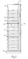
- a display device is shown in front view in figure 1 and in side view in figure 2.
- the device comprises two revolving product stands 11,12 extending from a shared base 10.
- Both revolving stands 11,12 have a substantially polygonal cross-section and are constructed around a vertical central shaft 13, wherein shaft 13 is rotatably connected to a baseplate 15 by means of a bearing 14.
- Mounted on both shafts 13 close to baseplate 15 is a toothed wheel 16, over which a toothed belt 17 is received which couples, and thus correspondingly drives, a rotation of the two shafts one-to-one.
- Both the baseplates and the belt transmission are hidden from view by a closed housing of base 10, which thus forms a plinth for the whole.
- both the shafts 13 and the toothed wheels, baseplates 15 and casing 10 are manufactured from steel. Otherwise the revolving product stand consists mainly of plastic.
- the coupling between both shafts can also comprise a toothed wheel, chain or V-belt transmission instead of an optionally toothed belt transmission, and a certain indirect coupling can be applied here if desired, whereby the one revolving stand co-rotates over a certain offset angle only after a rotation of the other revolving stand.
- Both revolving product stands have a modular construction through a stacking of individual product holder elements 30 on the central shaft, see also figure 3 which shows a cross-section along line III-III of figure 1.
- the product holder elements have an equilateral triangular cross-section and are placed separately on shaft 13.
- a three-sided column providing equal space to products on all sides can thus be assembled to a desired height.
- a bar handle 20 with which the column can be rotated, as well as a bumper 21 which provides protection from shopping carts, prams, wheelchairs and the like.
- Columns 11,12 are finished with a round tube 22 which provides space for text or decoration and is connected to a rear wall by means of a bracket 23 for the purpose of an increased stability of the whole.
- the shafts of both revolving product stands 11,12 are both provided with resetting means which always return the revolving product stands to a rest position after rotation.
- the resetting means are here formed by a set of oppositely rotating discs (not shown) in shaft 13, which force the revolving product stand upward during rotation and drive them back to a starting position under the influence of gravity.
- Diverse other active and passive solutions having the same or a similar effect can be selected.
- the display device will always return to an orderly starting position, which gives an orderly appearance and furthermore presents the products as optimally as possible.
- FIG 1 a starting position is chosen in which two triangle sides of both columns 11,12 lie mutually in line, see also figure 3, and together form a practically continuous front which provides a full view of the products present on these sides.
- Figure 3 is on the other hand based on a more prismatic view of columns 11,12 in which in the rest position the sides lying in line are situated here on a rear side, and the columns face toward the viewer with a corner. Although there is thus less of a view of the products from the front than in a frontal view as in figure 1, more products are in this way presented simultaneously.
- Plastic elements 30 are shown in more detail in figures 3-5 and are each moulded substantially integrally from a suitable plastic such as polyethylene, polypropylene or ABS.
- Plastic elements 30 comprise a relatively solid central part with the desired polygonal cross-section, in this case of an equilateral triangle. Situated at the corners of the central part are slightly rounded column-like parts 31-33, while the sides of the central part provide space for product holders 34 in which or on which the products for displaying can be received.
- the product holders here comprise a compartment 34 with a rear wall 35.
- Column-like parts 31-33 are given a hollow and slightly conical form.
- Product holder elements 30 are thus mutually stackable, wherein at the position of at least the column-like parts 31-33 the elements nest in each other slightly for a stable and aligned stacking.
- the product holder elements are moreover fixed on shaft 13 of the revolving stand by non-round opening 36 and likewise shaft 13.
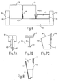
- Compartments 34 provide space for separate products. If desired, compartments 34 can be divided in separate shelves by placing one or more dividing members 40 therein, see figures 6-8. Dividing members 40 are moulded integrally from one plastic and comprise a partition 41 which, using a clip 42 formed thereon, can be hooked over rear wall 35 of the compartments. The dividing member is then placed or slid into the desired position on the rear wall. If desired, recesses and complementary ribs or projections can be formed for this purpose in or on the rear wall and clip in order to define preferred positions corresponding to commonly occurring product sizes. In this example use is made of a compartment width of about 375 millimetres for receiving three CD cases 50 or postcards, or a standard DVD case and postcard or CD case next to each other as desired. A stop member 43 in the form of a widening on a front side of partition 41 herein prevents the cases or other products being able to fall out of compartment 34 unexpectedly. A comparable stop member 44 is formed on either side in compartment 34.
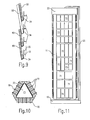
- Figure 9 shows schematically a number of product holder elements 30 of the device of figure 1 in filled state. Due to a relative vertical pitch of about 130 millimetres, or about the height of columns 31-33, of product holder elements 30 it is thus possible to place standard CD cases 50 and postcards 60 above each other and mixed with each other as desired.
- the display device is thus highly suitable for office stationers, bookshops, newspaper stands, record shops and related applications.
- a second embodiment of a display device according to the invention is shown in figures 10 and 11.
- the display device here also comprises a column-like revolving product stand 11 which is constructed from individual product holder elements, see figure 10, comparable to those of the first exemplary embodiment, although in this case the product holders comprise on the polygonal sides thereof product hooks 70 from which separate products 71,72,73,74 can be suspended.
- a column-like revolving product stand 11 which is constructed from individual product holder elements, see figure 10, comparable to those of the first exemplary embodiment, although in this case the product holders comprise on the polygonal sides thereof product hooks 70 from which separate products 71,72,73,74 can be suspended.
- different sizes of blister packs or otherwise packaged products can thus be arranged in orderly fashion, wherein mutatis mutandis the display device has all the advantages and aspects of the above described display device.
Landscapes
- Display Racks (AREA)
Abstract
Description
- The present invention relates to a display device, comprising at least two freely rotatable, i.e. not motor-driven, revolving product stands which both comprise a product column, with an at least substantially polygonal cross-section transversely of a vertical axis thereof, which product column is arranged freely rotatably about the vertical axis. The invention also relates to a product holder and dividing element for application in such a display device.
- A display device of the above stated type can be particularly applied for displaying and exhibiting products such as diverse types of article and paper products at for instance trade fairs, markets and in shops. Particularly in a shop environment it is of great importance here that as many products as possible can be displayed in clearly visible manner on the smallest possible floor area. With a view hereto the display device provides a multisided revolving product stand or stand which provides space on all sides to products for displaying, which are herein arranged for instance next to each other and above each other. In known display devices these are individual, standalone revolving product stands which are placed next to each other or at least together. The revolving stands herein maintain a sufficient mutual distance to allow a free rotation about their axiss.
- A drawback of such a known arrangement is that, in order to be able to guarantee an unimpeded rotation of the individual revolving stands under all circumstances, an intermediate space must be maintained therebetween which space is thereby not available for products. This has an adverse effect on the degree of utilization of the available floor surface area.
- The present invention has for its object, among others, to provide a display device whereby a more optimal use can be made of an available space.
- In order to achieve the intended object a display device of the type stated in the preamble has the feature according to the invention that the revolving product stands are placed on a shared base and that a coupling exists between the shafts of the revolving product stands, whereby rotations of the revolving product stands correspond to each other. By thus making the rotations of the separate revolving product stands correspond to each other and fixing the revolving product stands on a shared base the mutual distance between the revolving stands can be kept to a minimum, while mutual collision is nevertheless precluded. This correspondence can for instance consist of a blocking or fixation of one of the revolving stands in a starting position when the other one is moved. In a particular embodiment the display device according to the invention has the feature however that the coupling comprises a one-to-one transmission. A rotation of one of the revolving product stands thus results in the same rotation of the other revolving product stand(s) so that the products situated therein are likewise shown to the public.
- Owing to the coupling the revolving stands herein move in phase with each other in each case and are not in opposite phase, whereby a mutual collision can be avoided even at a mutual pitch equal to a width of one of the sides of the revolving stands. In a further particular embodiment the display device according to the invention herein has the feature that the transmission comprises a toothed belt. Such a toothed belt has the advantage that, even after years of use, no play occurs herein, or hardly so, while the costs thereof are relatively low.
- A preferred embodiment of the display device according to the invention has the feature that the revolving product stand herein provides space for products on each triangle side and is found in practice to provide an exceptionally good view of the products present therein.
A particular embodiment of the display device according to the invention herein has the feature that the revolving product stands have at least one rest position in which triangle sides of the revolving product stands lie at least substantially mutually in line and to which the revolving product stands return after a rotation. The rest position can herein be actively imposed by for instance a torsion spring which engages on the shaft of the revolving product stand, or passively by means of for instance a rise profile or screw thread in which the revolving stand rises when rotated and then drops automatically under the influence of gravity. The rest position ensures in each case a defined starting position, whereby the appearance of the revolving product stands will always be well-ordered and the products are displayed optimally. In a further particular embodiment the display device according to the invention is herein characterized in that the triangle sides are situated on a rear side of the revolving product stands. In this case a visual side of the revolving stands provides a prismatic view at all times of two triangle sides per revolving stand, whereby all products are always visible on these two sides. - A further particular embodiment of the display device according to the invention has the feature that the revolving product stands are placed in a row and that a rear wall is placed at least substantially parallel thereto, which extends over at least a significant part of a height and width formed by the revolving product stands. The rear wall herein provides a setting for the display device, which is hereby less dependent on the immediate surroundings for an optimal presentation of the products accommodated therein. The rear wall can furthermore be given a mirror form in order to provide a view from all sides of the products in the display device.
- A further preferred embodiment of the display device has the feature that the product column is constructed from a number of mutually stacked, practically identical product holder elements of a substantially polygonal cross-section directed transversely of the shaft with polygonal sides, that the product holder elements comprise a product holder on each polygonal side for receiving one or more products, and that the product holder elements comprise an opening inside the polygonal sides for receiving the shaft of the revolving product stand therein. The revolving product stand is herein assembled substantially of uniform, mutually stackable product holder elements, which can here be placed on top of each other to any desired height. Not only is such a modular construction a great advantage from a production viewpoint, it also improves the flexibility and utility thereof for the end user. This latter need only hold a sufficient number of separate product holder elements in stock, and can hereby assemble different heights and types of display device in accordance with his/her possibly temporary requirements. These are not only display devices of the above stated type, wherein the products are always disposed rotatably about a shaft. The invention also relates to a display device comprising at least one product stand for receiving a number of products around a shared shaft, which is characterized in that the product stand is constructed from a number of mutually stacked, practically identical product holder elements with a substantially polygonal cross-section with polygonal sides directed transversely of the shaft, and that the product holder elements comprise on each polygonal side a product holder for receiving one or more products. Such a stand can also be used statically, in addition to rotating as a revolving stand. The modular construction here also provides the option of construction to any desired height and of stocking only a limited supply of product holder elements.
- A preferred embodiment of the display device according to the invention herein has the feature that the product holder elements comprise an opening inside the polygonal sides for receiving therein a separate, non-round shaft of the stand. By thus using a non-round shaft and sliding the product holder elements thereon, the product holder elements are fixed in at least a horizontal plane and so exactly aligned relative to each other. This facilitates the mutual stacking and enhances the stability of the whole. In a further particular embodiment the display device herein has the feature that the shaft extends rotatably from a base. The stand thus provides a revolving product stand or carousel which provides a view of the products on all sides by means of rotation.
- In order to increase the stability of the whole and mutual fixation of the separate elements, a further preferred embodiment of the display device according to the invention has the feature that the product holder elements are nested in each other over a small part of their height.
- A particular embodiment of the display device according to the invention has the feature that product holders of the product holder elements comprise an open compartment on each polygonal side for receiving one or more products therein. The compartments form trays in which products can be removably accommodated. In order to enable a certain further subdivision here, a further particular embodiment of the display device according to the invention has the feature that the compartments are divided into separate shelves in a width direction by at least one dividing member. The dividing members can be arranged in the compartments in a number and position as desired in order to thus create therein separate shelves on either side, in which different products can be placed.
- A further particular embodiment of the display device according to the invention herein has the feature that the compartments comprise a rear wall and the dividing member is hooked over the rear wall by a fixing member extending therefrom. The largest possible part of the height of larger products preferably protrudes above the compartment so as to thus be more readily visible. In order to prevent such products from falling out, a further particular embodiment of the display device according to the invention has the feature that the dividing member comprises a stop member on a side remote from the rear wall for receiving a product thereagainst.
- A particularly attractive and effective presentation of the products received in the stand is found possible with a particular embodiment of a display device according to the invention, characterized in that the product holder elements have a substantially triangular, more specifically equilateral cross-section.
- The invention also relates to a product holder element and dividing member as described above and will be further elucidated on the basis of a number of exemplary embodiments and an associated drawing. In the drawing:
- figure 1
- shows a front view of a first embodiment of a display device according to the invention;
- figure 2
- shows a side view of the device of figure 1;
- figure 3
- shows a cross-section of the device of figure 1;
- figure 4
- shows a front view of a product holder element as applied in the device of figure 1;
- figure 5
- shows a cross-section of the product holder element of figure 4;
- figure 6
- shows a front view of the product holder element of figure 4 in filled state;
- figure 7A
- shows a front view of a dividing member as applied in the product holder element of figure 6;
- figure 7B
- shows a first cross-section of the dividing member as applied in the product holder element of figure 6;
- figure 7C
- shows a second cross-section of the dividing member as applied in the product holder element of figure 6;
- figure 8
- shows a cross-section of the product holder element of figure 6 having therein the dividing member of figures 7A-7C;
- figure 9
- shows a cross-section of the product holder of figure 6 in filled state;
- figure 10
- shows a cross-section of a second embodiment of a product holder element according to the invention; and
- figure 11
- shows a side view of a second embodiment of a display device according to the invention on the basis of the product holder element of figure 10.
- The figures are in principle schematic and not always drawn to scale. Some dimensions in particular can be exaggerated to a greater or lesser extent for the sake of clarity. Corresponding parts are designated in the figures with the same reference numeral.
- A display device according to the invention is shown in front view in figure 1 and in side view in figure 2. The device comprises two revolving product stands 11,12 extending from a shared
base 10. Both revolving stands 11,12 have a substantially polygonal cross-section and are constructed around a verticalcentral shaft 13, whereinshaft 13 is rotatably connected to abaseplate 15 by means of abearing 14. Mounted on bothshafts 13 close tobaseplate 15 is atoothed wheel 16, over which atoothed belt 17 is received which couples, and thus correspondingly drives, a rotation of the two shafts one-to-one. Both the baseplates and the belt transmission are hidden from view by a closed housing ofbase 10, which thus forms a plinth for the whole. With an eye to a desired robustness and durability, both theshafts 13 and the toothed wheels,baseplates 15 andcasing 10 are manufactured from steel. Otherwise the revolving product stand consists mainly of plastic. In addition, the coupling between both shafts can also comprise a toothed wheel, chain or V-belt transmission instead of an optionally toothed belt transmission, and a certain indirect coupling can be applied here if desired, whereby the one revolving stand co-rotates over a certain offset angle only after a rotation of the other revolving stand. - Both revolving product stands have a modular construction through a stacking of individual
product holder elements 30 on the central shaft, see also figure 3 which shows a cross-section along line III-III of figure 1. In this example the product holder elements have an equilateral triangular cross-section and are placed separately onshaft 13. A three-sided column providing equal space to products on all sides can thus be assembled to a desired height. Provided all around on bothcolumns bar handle 20, with which the column can be rotated, as well as abumper 21 which provides protection from shopping carts, prams, wheelchairs and the like.Columns round tube 22 which provides space for text or decoration and is connected to a rear wall by means of abracket 23 for the purpose of an increased stability of the whole. - The shafts of both revolving product stands 11,12 are both provided with resetting means which always return the revolving product stands to a rest position after rotation. The resetting means are here formed by a set of oppositely rotating discs (not shown) in
shaft 13, which force the revolving product stand upward during rotation and drive them back to a starting position under the influence of gravity. Diverse other active and passive solutions having the same or a similar effect can be selected. As a result of such an automatic resetting the display device will always return to an orderly starting position, which gives an orderly appearance and furthermore presents the products as optimally as possible. - In figure 1 a starting position is chosen in which two triangle sides of both
columns columns -
Product holder elements 30 are shown in more detail in figures 3-5 and are each moulded substantially integrally from a suitable plastic such as polyethylene, polypropylene or ABS.Plastic elements 30 comprise a relatively solid central part with the desired polygonal cross-section, in this case of an equilateral triangle. Situated at the corners of the central part are slightly rounded column-like parts 31-33, while the sides of the central part provide space forproduct holders 34 in which or on which the products for displaying can be received. On each side the product holders here comprise acompartment 34 with arear wall 35. - Column-like parts 31-33 are given a hollow and slightly conical form.
Product holder elements 30 are thus mutually stackable, wherein at the position of at least the column-like parts 31-33 the elements nest in each other slightly for a stable and aligned stacking. The product holder elements are moreover fixed onshaft 13 of the revolving stand bynon-round opening 36 and likewiseshaft 13. -
Compartments 34 provide space for separate products. If desired, compartments 34 can be divided in separate shelves by placing one ormore dividing members 40 therein, see figures 6-8. Dividingmembers 40 are moulded integrally from one plastic and comprise apartition 41 which, using aclip 42 formed thereon, can be hooked overrear wall 35 of the compartments. The dividing member is then placed or slid into the desired position on the rear wall. If desired, recesses and complementary ribs or projections can be formed for this purpose in or on the rear wall and clip in order to define preferred positions corresponding to commonly occurring product sizes. In this example use is made of a compartment width of about 375 millimetres for receiving threeCD cases 50 or postcards, or a standard DVD case and postcard or CD case next to each other as desired. Astop member 43 in the form of a widening on a front side ofpartition 41 herein prevents the cases or other products being able to fall out ofcompartment 34 unexpectedly. Acomparable stop member 44 is formed on either side incompartment 34. - Figure 9 shows schematically a number of
product holder elements 30 of the device of figure 1 in filled state. Due to a relative vertical pitch of about 130 millimetres, or about the height of columns 31-33, ofproduct holder elements 30 it is thus possible to placestandard CD cases 50 andpostcards 60 above each other and mixed with each other as desired. The display device is thus highly suitable for office stationers, bookshops, newspaper stands, record shops and related applications. - A second embodiment of a display device according to the invention is shown in figures 10 and 11. The display device here also comprises a column-like revolving
product stand 11 which is constructed from individual product holder elements, see figure 10, comparable to those of the first exemplary embodiment, although in this case the product holders comprise on the polygonal sides thereof product hooks 70 from whichseparate products - Although the invention has been further elucidated with reference to only a few embodiments, it will be apparent that the invention is by no means limited thereto. On the contrary, many variations and embodiments are possible for the average skilled person within the scope of the invention.
Claims (20)
- Display device, comprising at least two freely rotatable revolving product stands which both comprise a product column, with an at least substantially polygonal cross-section transversely of a vertical axis thereof, which product column is arranged freely rotatably about the vertical axis, characterized in that the revolving product stands are placed on a shared base and that a coupling exists between the shafts of the revolving product stands, whereby rotations of the revolving product stands correspond to each other.
- Display device as claimed in claim 1, characterized in that the coupling comprises a one-to-one transmission.
- Display device as claimed in claim 2, characterized in that the transmission comprises a toothed belt.
- Display device as claimed in one or more of the foregoing claims, characterized in that the revolving product stands have a triangular cross-section, and more specifically that of a substantially equilateral triangle, transversely of the vertical shaft thereof .
- Display device as claimed in claim 4, characterized in that the revolving product stands have at least one rest position in which triangle sides of the revolving product stands lie at least substantially mutually in line and to which the revolving product stands return after a rotation.
- Display device as claimed in claim 5, characterized in that the triangle sides are situated on a rear side of the revolving product stands in the rest position.
- Display device as claimed in one or more of the foregoing claims, characterized in that the revolving product stands are placed in a row and that a rear wall is placed at least substantially parallel thereto, which extends over at least a significant part of a height and width formed by the revolving product stands.
- Display device as claimed in one or more of the foregoing claims, characterized in that the product column is constructed from a number of mutually stacked, practically identical product holder elements having transversely of the shaft a substantially polygonal cross-section with polygonal sides, that the product holder elements comprise a product holder on each polygonal side for receiving one or more products, and that the product holder elements comprise an opening inside the polygonal sides for receiving the shaft of the revolving product stand therein.
- Display device comprising at least one product stand for receiving a number of products around a shared shaft, characterized in that the product stand is constructed from a number of mutually stacked, practically identical product holder elements with a substantially polygonal cross-section with polygonal sides directed transversely of the shaft, and that the product holder elements comprise on each polygonal side a product holder for receiving one or more products.
- Display device as claimed in claim 8 or 9, characterized in that the product holder elements comprise an opening inside the polygonal sides for receiving therein a separate, non-round shaft of the stand.
- Display device as claimed in claims 8, 9 or 10, characterized in that the shaft extends rotatably from a base.
- Display device as claimed in claims 8, 9, 10 or 11, characterized in that the product holder elements are nested in each other over a small part of their height.
- Display device as claimed in one or more of the claims 8-12, characterized in that product holders of the product holder elements comprise an open compartment on each polygonal side for receiving one or more products therein.
- Display device as claimed in claim 13, characterized in that the compartments are divided into separate shelves in a width direction by at least one dividing member.
- Display device as claimed in claim 14, characterized in that the compartments comprise a rear wall and the dividing member is hooked over the rear wall by a fixing member extending therefrom.
- Display device as claimed in claim 14 or 15, characterized in that the dividing member comprises a stop member on a side remote from the rear wall for receiving a product thereagainst.
- Display device as claimed in one or more of the claims 8-16, characterized in that the product holder elements have a substantially triangular, more specifically equilateral cross-section.
- Display device as claimed in one or more of the claims 8-17, characterized in that the product holder elements are formed substantially integrally from one moulded plastic part.
- Product holder element for application in the display device as claimed in one or more of the claims 8-18.
- Dividing member for application in a product holder element of the display device as claimed in claim 16, 17 or 18.
Applications Claiming Priority (1)
| Application Number | Priority Date | Filing Date | Title |
|---|---|---|---|
| NL1028654A NL1028654C2 (en) | 2005-03-30 | 2005-03-30 | Display device. |
Publications (1)
| Publication Number | Publication Date |
|---|---|
| EP1707083A1 true EP1707083A1 (en) | 2006-10-04 |
Family
ID=34975035
Family Applications (1)
| Application Number | Title | Priority Date | Filing Date |
|---|---|---|---|
| EP06075752A Withdrawn EP1707083A1 (en) | 2005-03-30 | 2006-03-28 | Display device |
Country Status (3)
| Country | Link |
|---|---|
| US (1) | US20060225325A1 (en) |
| EP (1) | EP1707083A1 (en) |
| NL (1) | NL1028654C2 (en) |
Families Citing this family (1)
| Publication number | Priority date | Publication date | Assignee | Title |
|---|---|---|---|---|
| US7963060B2 (en) * | 2007-10-01 | 2011-06-21 | Mechtronics Corporation | Product display device |
Citations (7)
| Publication number | Priority date | Publication date | Assignee | Title |
|---|---|---|---|---|
| GB1444469A (en) * | 1973-05-05 | 1976-07-28 | Schaefer Gmbh Fritz | Shelving |
| AU2102477A (en) * | 1976-01-05 | 1978-07-13 | R M S Shopfitters Limited | Display stands |
| DE2916810A1 (en) * | 1979-04-26 | 1980-11-06 | Reinhold Ott | Records and cassettes display - consists of two cylinders synchronously driven with in line drive shafts |
| FR2609879A1 (en) * | 1987-01-26 | 1988-07-29 | Heyberger Paul | Rotary and synchronised dynamic multi-display device with a constant and adjustable cycle |
| DE29516260U1 (en) * | 1995-10-13 | 1995-12-21 | Benadda, Ahmed, 34125 Kassel | Drive device for a rotatable presentation element |
| US6206493B1 (en) * | 1999-07-22 | 2001-03-27 | Collector's Museum, Llc | Display structure for collectibles |
| FR2825254A1 (en) * | 2001-05-29 | 2002-12-06 | Gabriel Ramond Sa | Modular display stand for jam pots has support base for magazine with modular holders having cut outs to aid removal of pots |
Family Cites Families (9)
| Publication number | Priority date | Publication date | Assignee | Title |
|---|---|---|---|---|
| GB2227164B (en) * | 1988-11-23 | 1992-01-22 | Alec John Jacobs | Plant pot support |
| US5253767A (en) * | 1991-12-12 | 1993-10-19 | Gressco, Ltd. | Rotatable display tower for compact discs and the like |
| USD358279S (en) * | 1993-12-02 | 1995-05-16 | The Croydon Company, Inc. | Multi-media display tower |
| US5690399A (en) * | 1996-04-05 | 1997-11-25 | Davis; Randal H. | Compact disk stroage cabinet |
| GB2350785A (en) * | 1999-05-22 | 2000-12-13 | Douglas Andrew Whitworth | Cardboard rotary display stand |
| DE20107825U1 (en) * | 2001-05-09 | 2001-08-02 | Sunhing Millennium Ltd., Kowloon | Stand with split footplate for storing flat objects |
| US7185769B2 (en) * | 2001-07-20 | 2007-03-06 | Timothy Glass | Article storage display tower |
| WO2003099680A1 (en) * | 2002-05-24 | 2003-12-04 | Takashi Ito | Disc stand |
| US6766914B1 (en) * | 2003-06-09 | 2004-07-27 | Ciro Rios | Multiple configuration display |
-
2005
- 2005-03-30 NL NL1028654A patent/NL1028654C2/en not_active IP Right Cessation
-
2006
- 2006-03-28 EP EP06075752A patent/EP1707083A1/en not_active Withdrawn
- 2006-03-30 US US11/392,672 patent/US20060225325A1/en not_active Abandoned
Patent Citations (7)
| Publication number | Priority date | Publication date | Assignee | Title |
|---|---|---|---|---|
| GB1444469A (en) * | 1973-05-05 | 1976-07-28 | Schaefer Gmbh Fritz | Shelving |
| AU2102477A (en) * | 1976-01-05 | 1978-07-13 | R M S Shopfitters Limited | Display stands |
| DE2916810A1 (en) * | 1979-04-26 | 1980-11-06 | Reinhold Ott | Records and cassettes display - consists of two cylinders synchronously driven with in line drive shafts |
| FR2609879A1 (en) * | 1987-01-26 | 1988-07-29 | Heyberger Paul | Rotary and synchronised dynamic multi-display device with a constant and adjustable cycle |
| DE29516260U1 (en) * | 1995-10-13 | 1995-12-21 | Benadda, Ahmed, 34125 Kassel | Drive device for a rotatable presentation element |
| US6206493B1 (en) * | 1999-07-22 | 2001-03-27 | Collector's Museum, Llc | Display structure for collectibles |
| FR2825254A1 (en) * | 2001-05-29 | 2002-12-06 | Gabriel Ramond Sa | Modular display stand for jam pots has support base for magazine with modular holders having cut outs to aid removal of pots |
Also Published As
| Publication number | Publication date |
|---|---|
| US20060225325A1 (en) | 2006-10-12 |
| NL1028654C2 (en) | 2006-10-03 |
Similar Documents
| Publication | Publication Date | Title |
|---|---|---|
| US4478337A (en) | Adjustable shelving unit | |
| US8733563B2 (en) | Display unit with interchangeable shelving | |
| US4030608A (en) | Article display stand | |
| US4653651A (en) | Stackable shelving system | |
| US9211009B2 (en) | Apparatus for storing and retrieving varying shaped and sized spice bottles or containers | |
| US4387810A (en) | Shingled rack display device | |
| JP5508536B2 (en) | Retail product display system with drawers with movable display product locator in front | |
| US8651288B2 (en) | Shelf and merchandise display system | |
| US4750623A (en) | Stackable shelving system | |
| WO2017008111A1 (en) | An anti-theft storage and display assembly | |
| US5394997A (en) | Rack for newspapers | |
| KR20150000954U (en) | Display table for umbrella | |
| US5839587A (en) | Lens display system | |
| CA2293641C (en) | Display rack | |
| CA2024736C (en) | Merchandising display unit | |
| US4998629A (en) | Display and storage rack | |
| US6942109B2 (en) | Rotary display apparatus for displaying periodicals in a circular array | |
| US7367460B2 (en) | Customizable display unit | |
| EP1707083A1 (en) | Display device | |
| US9445674B2 (en) | Gravity fed shelving display system | |
| US8479927B2 (en) | Gravity fed peg merchandising system | |
| NL1031794C2 (en) | Display device for exhibiting products in e.g. shops, has revolving product stands coupled using toothed belt such that rotation of revolving product stands correspond to each other | |
| EP1740074A2 (en) | Modular display rack | |
| US4703703A (en) | Variable width, tiered display stand | |
| US20080110843A1 (en) | Display System |
Legal Events
| Date | Code | Title | Description |
|---|---|---|---|
| PUAI | Public reference made under article 153(3) epc to a published international application that has entered the european phase |
Free format text: ORIGINAL CODE: 0009012 |
|
| AK | Designated contracting states |
Kind code of ref document: A1 Designated state(s): AT BE BG CH CY CZ DE DK EE ES FI FR GB GR HU IE IS IT LI LT LU LV MC NL PL PT RO SE SI SK TR |
|
| AX | Request for extension of the european patent |
Extension state: AL BA HR MK YU |
|
| 17P | Request for examination filed |
Effective date: 20070404 |
|
| AKX | Designation fees paid |
Designated state(s): AT BE BG CH CY CZ DE DK EE ES FI FR GB GR HU IE IS IT LI LT LU LV MC NL PL PT RO SE SI SK TR |
|
| 17Q | First examination report despatched |
Effective date: 20070614 |
|
| STAA | Information on the status of an ep patent application or granted ep patent |
Free format text: STATUS: THE APPLICATION IS DEEMED TO BE WITHDRAWN |
|
| 18D | Application deemed to be withdrawn |
Effective date: 20111001 |