EP1705891A1 - Driving device for scanner - Google Patents
Driving device for scanner Download PDFInfo
- Publication number
- EP1705891A1 EP1705891A1 EP05290653A EP05290653A EP1705891A1 EP 1705891 A1 EP1705891 A1 EP 1705891A1 EP 05290653 A EP05290653 A EP 05290653A EP 05290653 A EP05290653 A EP 05290653A EP 1705891 A1 EP1705891 A1 EP 1705891A1
- Authority
- EP
- European Patent Office
- Prior art keywords
- bar
- belt drive
- motion
- guide elements
- guide
- Prior art date
- Legal status (The legal status is an assumption and is not a legal conclusion. Google has not performed a legal analysis and makes no representation as to the accuracy of the status listed.)
- Granted
Links
- 230000033001 locomotion Effects 0.000 claims abstract description 16
- 239000000725 suspension Substances 0.000 claims abstract description 9
- 125000006850 spacer group Chemical group 0.000 claims description 6
- 238000005096 rolling process Methods 0.000 claims description 2
- 239000011521 glass Substances 0.000 description 4
- 238000004519 manufacturing process Methods 0.000 description 2
- 230000005540 biological transmission Effects 0.000 description 1
- 238000010276 construction Methods 0.000 description 1
- 238000013016 damping Methods 0.000 description 1
- 238000006073 displacement reaction Methods 0.000 description 1
- 230000000694 effects Effects 0.000 description 1
- 238000002347 injection Methods 0.000 description 1
- 239000007924 injection Substances 0.000 description 1
- 230000010355 oscillation Effects 0.000 description 1
Images
Classifications
-
- H—ELECTRICITY
- H04—ELECTRIC COMMUNICATION TECHNIQUE
- H04N—PICTORIAL COMMUNICATION, e.g. TELEVISION
- H04N1/00—Scanning, transmission or reproduction of documents or the like, e.g. facsimile transmission; Details thereof
- H04N1/04—Scanning arrangements, i.e. arrangements for the displacement of active reading or reproducing elements relative to the original or reproducing medium, or vice versa
-
- H—ELECTRICITY
- H04—ELECTRIC COMMUNICATION TECHNIQUE
- H04N—PICTORIAL COMMUNICATION, e.g. TELEVISION
- H04N1/00—Scanning, transmission or reproduction of documents or the like, e.g. facsimile transmission; Details thereof
- H04N1/04—Scanning arrangements, i.e. arrangements for the displacement of active reading or reproducing elements relative to the original or reproducing medium, or vice versa
- H04N1/10—Scanning arrangements, i.e. arrangements for the displacement of active reading or reproducing elements relative to the original or reproducing medium, or vice versa using flat picture-bearing surfaces
- H04N1/1013—Scanning arrangements, i.e. arrangements for the displacement of active reading or reproducing elements relative to the original or reproducing medium, or vice versa using flat picture-bearing surfaces with sub-scanning by translatory movement of at least a part of the main-scanning components
-
- H—ELECTRICITY
- H04—ELECTRIC COMMUNICATION TECHNIQUE
- H04N—PICTORIAL COMMUNICATION, e.g. TELEVISION
- H04N1/00—Scanning, transmission or reproduction of documents or the like, e.g. facsimile transmission; Details thereof
- H04N1/04—Scanning arrangements, i.e. arrangements for the displacement of active reading or reproducing elements relative to the original or reproducing medium, or vice versa
- H04N1/10—Scanning arrangements, i.e. arrangements for the displacement of active reading or reproducing elements relative to the original or reproducing medium, or vice versa using flat picture-bearing surfaces
- H04N1/1013—Scanning arrangements, i.e. arrangements for the displacement of active reading or reproducing elements relative to the original or reproducing medium, or vice versa using flat picture-bearing surfaces with sub-scanning by translatory movement of at least a part of the main-scanning components
- H04N1/1026—Scanning arrangements, i.e. arrangements for the displacement of active reading or reproducing elements relative to the original or reproducing medium, or vice versa using flat picture-bearing surfaces with sub-scanning by translatory movement of at least a part of the main-scanning components using a belt or cable
-
- H—ELECTRICITY
- H04—ELECTRIC COMMUNICATION TECHNIQUE
- H04N—PICTORIAL COMMUNICATION, e.g. TELEVISION
- H04N1/00—Scanning, transmission or reproduction of documents or the like, e.g. facsimile transmission; Details thereof
- H04N1/04—Scanning arrangements, i.e. arrangements for the displacement of active reading or reproducing elements relative to the original or reproducing medium, or vice versa
- H04N1/10—Scanning arrangements, i.e. arrangements for the displacement of active reading or reproducing elements relative to the original or reproducing medium, or vice versa using flat picture-bearing surfaces
- H04N1/1013—Scanning arrangements, i.e. arrangements for the displacement of active reading or reproducing elements relative to the original or reproducing medium, or vice versa using flat picture-bearing surfaces with sub-scanning by translatory movement of at least a part of the main-scanning components
- H04N1/1039—Movement of the main scanning components
- H04N1/1043—Movement of the main scanning components of a sensor array
-
- H—ELECTRICITY
- H04—ELECTRIC COMMUNICATION TECHNIQUE
- H04N—PICTORIAL COMMUNICATION, e.g. TELEVISION
- H04N2201/00—Indexing scheme relating to scanning, transmission or reproduction of documents or the like, and to details thereof
- H04N2201/04—Scanning arrangements
- H04N2201/0402—Arrangements not specific to a particular one of the scanning methods covered by groups H04N1/04 - H04N1/207
- H04N2201/0442—Details of scanning carriage or moving picture-bearing surface support, e.g. bearing contact with guide rails
Definitions
- the present invention relates to a system for driving and guiding a bar, particularly a reading bar of a scanner, the bar being drivable using a belt drive along a movement direction transverse to the longitudinal direction of the bar.
- the bar is typically guided at its edges using guide devices, such as toothed racks.
- the bar is typically pressed against a glass plate in operation, due to which a counterforce must be applied by the guide. Particularly because of thermally caused deformations and/or dirt, constraining forces may cause a permanent deformation of these guides as a result of a slight play.
- the object of the present invention is to specify a drive of the type cited at the beginning in which the known disadvantages are avoided, which has a simple construction, adequate precision, and only slight play, whose precision is essentially constant over its service life, and which may be manufactured simply and cost-effectively.
- the belt drive engages at two suspension points of the bar, which are offset in the longitudinal direction of the bar, while implementing a torque
- the bar comprises guide elements, the guide elements being positioned offset in the direction of motion and engaging on different sides of a guide strip positioned in the direction of motion due to the torque.
- the belt drive is also used for aligning the bar in relation to the guide strip, through which an especially simple design of the drive is achieved.
- the guide strip is positioned essentially perpendicularly to the area passed over by the bar, because of which a load of the bar in this direction does not cause deformation of the guide strip. Due to the non-positive alignment of the bar, the bar may possibly twist against the direction of force, permanent deformation of the drive being avoided even if the bar is temporarily caught because of dirt or the like.
- a tension element particularly a spring element, may be assigned to at least one of the suspension points.
- the tension element it may be ensured easily that the belt drive is always loaded with a tensile force and a torque is applied to the bar.
- the belt drive may comprise at least one spring-loaded deflection pulley. Through the spring-loaded deflection pulley, it may be ensured that the belt drive is always loaded with a tensile force and a torque is applied to the bar.
- At least one of the guide elements may comprise a caster. Through the caster, the friction of the guide elements may be kept low and uniform motion of the bar may be ensured.
- At least one of the guide elements may have a spacer element projecting from the bar.
- the spacing of the guide elements may be selected largely independently of the dimension of the bar, the contact pressures arising between the guide strip and the guide elements particularly being a function of this spacing.
- the guide strip may be positioned in the housing and connected in one piece to the housing, through which the manufacturing costs may be kept especially low.
- the guiding occurs nearly exclusively via the guide strip, because of which special requirements in regard to precision are only required on the guide strip even during manufacturing.
- the bar may comprise at least one support roller for rolling on a running surface. Forces may be transmitted from the bar by the support roller independently from the guide strip, through which the strain of the guide may be kept low.
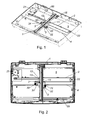
- Figure 1 shows an oblique view of a housing of a scanner having a drive according to the present invention
- Figure 2 shows a top view of the housing shown in Figure 1.
- Figures 1 and 2 show a system according to the present invention for driving and guiding a bar 1.
- the bar 1 is drivable using a belt drive 2 along a direction of motion transverse to the longitudinal direction of the bar 1.
- the drive is especially suitable for a reading bar of a scanner. In this case, the drive must have an adequate precision, corresponding to the resolution of the scanner, because of which guiding of the bar 1 essentially without play is necessary.
- the belt drive 2 engages on two suspension points 11, 12 of the bar 1, which are offset in the longitudinal direction of the bar 1, to implement a torque, the belt drive 2 having a tensile load applied to it.
- the torque is essentially a function of the perpendicular spacing of the suspension points 11, 12 and the force applied by the belt drive 2.
- the bar 1 comprises guide elements 3, the guide elements 3 being positioned offset in the direction of motion and engaging due to the torque on different sides of a guide strip 4 positioned in the direction of motion.
- the belt drive 2 is used not only for the motion in the direction of motion, but rather also for aligning the bar 1 on the guide strip 4.
- a tensile force of the belt drive may be ensured easily if a tension element 13, which may particularly be a spring element, is assigned to at least one of the suspension points 11, 12.
- the tension element 13 may easily be connected on one end to one end of the belt drive and on the other end to one of the suspension points 11.
- the belt drive 2 may comprise at least one spring-loaded deflection pulley 22.
- a minimum tensile force in the belt drive 2 and thus the torque may also be ensured through the deflection pulley.
- the tensile force may also be applied by the drive unit 21.
- the guide strip 4 is implemented in one piece.
- the guide strip 4 may also comprise multiple partial strips, for example, two essentially parallel partial strips, the guide elements 3 each engaging on one side of the partial strips.
- the guide strip 4 may be positioned in the central third, particularly approximately in the middle, of the bar 1.
- the bar may be twisted in relation to the guide strip 4 and is held in a stop position by the torque. If it is positioned centrally, the bar 1 has a slight resistance torque to the twisting in relation to the guide strip 4, inertial effects being kept small.
- Displacement of the bar 1 along the guide strip 4 may be implemented with especially low friction if at least one of the guide elements 3 comprises a caster 31. Especially uniform motion of the bar 1 along the guide strip 4 may be ensured by the caster 31.
- the guide elements 3 may have spacer elements 32 projecting from the bar 1. Using the spacer elements 32, the spacing of the engagement points on the guide strip 4 may be selected largely independently of the dimensioning of the bar 1. Secure and precise alignment of the bar 1 may be ensured in this case. In other embodiments, only one of the guide elements 3 may have a spacer element 32.
- the guide strip 4 is typically positioned in a housing 5. In this case, it may be implemented as an independent component and attached in the housing 5. In other embodiments, the guide strip 4 may be connected in one piece to the housing 5, the housing 5 able to be implemented with the guide strip 4 as an injection molded part or the like.
- the guide strip 4 may essentially form a T-shaped profile with the adjoining part of the housing 5, high stability and strength of the guide strip 4 being achieved.
- the bar 1 may comprise at least one support roller 15 which may roll on a running surface 55, the running surface 55 able to be connected in one piece to the housing 5.
- the support roller 15 may be provided in this case for force transmission and/or damping of any oscillations of the bar 1. Guiding of the bar 1 via the support roller 15 is not necessary.
- the bar 1 may be guided below a glass pane, the implementation of a contact force between the bar 1 and the glass pane being provided, so that a predefinable spacing between the read unit and the glass pane is ensured.
- a contact force in this type may be transmitted easily by the support roller 15 to the housing 5.
Landscapes
- Engineering & Computer Science (AREA)
- Multimedia (AREA)
- Signal Processing (AREA)
- Facsimile Scanning Arrangements (AREA)
Abstract
Description
- The present invention relates to a system for driving and guiding a bar, particularly a reading bar of a scanner, the bar being drivable using a belt drive along a movement direction transverse to the longitudinal direction of the bar.
- In known systems of this type, the bar is typically guided at its edges using guide devices, such as toothed racks.
- It is necessary in this case to align the guide devices at the edges in relation to one another. The bar is typically pressed against a glass plate in operation, due to which a counterforce must be applied by the guide. Particularly because of thermally caused deformations and/or dirt, constraining forces may cause a permanent deformation of these guides as a result of a slight play.
- The object of the present invention is to specify a drive of the type cited at the beginning in which the known disadvantages are avoided, which has a simple construction, adequate precision, and only slight play, whose precision is essentially constant over its service life, and which may be manufactured simply and cost-effectively.
- This is achieved according to the present invention in that the belt drive engages at two suspension points of the bar, which are offset in the longitudinal direction of the bar, while implementing a torque, and the bar comprises guide elements, the guide elements being positioned offset in the direction of motion and engaging on different sides of a guide strip positioned in the direction of motion due to the torque.
- It is advantageous in this case that, in addition to moving the bar, the belt drive is also used for aligning the bar in relation to the guide strip, through which an especially simple design of the drive is achieved. The guide strip is positioned essentially perpendicularly to the area passed over by the bar, because of which a load of the bar in this direction does not cause deformation of the guide strip. Due to the non-positive alignment of the bar, the bar may possibly twist against the direction of force, permanent deformation of the drive being avoided even if the bar is temporarily caught because of dirt or the like.
- In a refinement of the present invention, a tension element, particularly a spring element, may be assigned to at least one of the suspension points. Through the tension element, it may be ensured easily that the belt drive is always loaded with a tensile force and a torque is applied to the bar.
- According to another embodiment of the present invention, the belt drive may comprise at least one spring-loaded deflection pulley. Through the spring-loaded deflection pulley, it may be ensured that the belt drive is always loaded with a tensile force and a torque is applied to the bar.
- In a further embodiment of the present invention, at least one of the guide elements may comprise a caster. Through the caster, the friction of the guide elements may be kept low and uniform motion of the bar may be ensured.
- In a refinement of the present invention, at least one of the guide elements may have a spacer element projecting from the bar. Through the spacer element, the spacing of the guide elements may be selected largely independently of the dimension of the bar, the contact pressures arising between the guide strip and the guide elements particularly being a function of this spacing.
- According to a further embodiment of the present invention, the guide strip may be positioned in the housing and connected in one piece to the housing, through which the manufacturing costs may be kept especially low. The guiding occurs nearly exclusively via the guide strip, because of which special requirements in regard to precision are only required on the guide strip even during manufacturing.
- According to a further embodiment of the present invention, the bar may comprise at least one support roller for rolling on a running surface. Forces may be transmitted from the bar by the support roller independently from the guide strip, through which the strain of the guide may be kept low.
- The present invention will be described in greater detail with reference to the attached drawing, in which embodiments are shown.
- Figure 1 shows an oblique view of a housing of a scanner having a drive according to the present invention; and
- Figure 2 shows a top view of the housing shown in Figure 1.
- Figures 1 and 2 show a system according to the present invention for driving and guiding a bar 1. The bar 1 is drivable using a
belt drive 2 along a direction of motion transverse to the longitudinal direction of the bar 1. The drive is especially suitable for a reading bar of a scanner. In this case, the drive must have an adequate precision, corresponding to the resolution of the scanner, because of which guiding of the bar 1 essentially without play is necessary. - In the drive, the
belt drive 2 engages on twosuspension points belt drive 2 having a tensile load applied to it. The torque is essentially a function of the perpendicular spacing of thesuspension points belt drive 2. Furthermore, the bar 1 comprisesguide elements 3, theguide elements 3 being positioned offset in the direction of motion and engaging due to the torque on different sides of a guide strip 4 positioned in the direction of motion. In this drive, thebelt drive 2 is used not only for the motion in the direction of motion, but rather also for aligning the bar 1 on the guide strip 4. - A tensile force of the belt drive may be ensured easily if a
tension element 13, which may particularly be a spring element, is assigned to at least one of thesuspension points tension element 13 may easily be connected on one end to one end of the belt drive and on the other end to one of thesuspension points 11. - In another embodiment, the
belt drive 2 may comprise at least one spring-loadeddeflection pulley 22. A minimum tensile force in thebelt drive 2 and thus the torque may also be ensured through the deflection pulley. The tensile force may also be applied by thedrive unit 21. - In the embodiment shown, the guide strip 4 is implemented in one piece. In other embodiments, the guide strip 4 may also comprise multiple partial strips, for example, two essentially parallel partial strips, the
guide elements 3 each engaging on one side of the partial strips. - The guide strip 4 may be positioned in the central third, particularly approximately in the middle, of the bar 1.
- The bar may be twisted in relation to the guide strip 4 and is held in a stop position by the torque. If it is positioned centrally, the bar 1 has a slight resistance torque to the twisting in relation to the guide strip 4, inertial effects being kept small.
- Displacement of the bar 1 along the guide strip 4 may be implemented with especially low friction if at least one of the
guide elements 3 comprises acaster 31. Especially uniform motion of the bar 1 along the guide strip 4 may be ensured by thecaster 31. - The
guide elements 3 may havespacer elements 32 projecting from the bar 1. Using thespacer elements 32, the spacing of the engagement points on the guide strip 4 may be selected largely independently of the dimensioning of the bar 1. Secure and precise alignment of the bar 1 may be ensured in this case. In other embodiments, only one of theguide elements 3 may have aspacer element 32. - The guide strip 4 is typically positioned in a housing 5. In this case, it may be implemented as an independent component and attached in the housing 5. In other embodiments, the guide strip 4 may be connected in one piece to the housing 5, the housing 5 able to be implemented with the guide strip 4 as an injection molded part or the like. The guide strip 4 may essentially form a T-shaped profile with the adjoining part of the housing 5, high stability and strength of the guide strip 4 being achieved.
- Furthermore, the bar 1 may comprise at least one
support roller 15 which may roll on a runningsurface 55, the runningsurface 55 able to be connected in one piece to the housing 5. Thesupport roller 15 may be provided in this case for force transmission and/or damping of any oscillations of the bar 1. Guiding of the bar 1 via thesupport roller 15 is not necessary. - If the system according to the present invention is used for the drive in a scanner, the bar 1 may be guided below a glass pane, the implementation of a contact force between the bar 1 and the glass pane being provided, so that a predefinable spacing between the read unit and the glass pane is ensured. A contact force in this type may be transmitted easily by the
support roller 15 to the housing 5.
Claims (7)
- A system for driving and guiding a bar (1), particularly a read bar of a scanner, the bar (1) being drivable using a belt drive (2) along a direction of motion transverse to the longitudinal direction of the bar (1), characterized in that the belt drive (2) engages on two suspension points (11, 12) of the bar (1), which are offset in the longitudinal direction of the bar (1), to implement a torque, and the bar (1) comprises guide elements (3), the guide elements (3) being positioned offset in the direction of motion and engaging due to the torque on different sides of a guide strip (4) positioned in the direction of motion.
- The system according to Claim 1,
characterized in that a tension element (13), particularly a spring element, is assigned to at least one of the suspension points (11, 12). - The system according to Claim 1 or 2,
characterized in that the belt drive (2) comprises at least one spring-loaded deflection pulley (22). - The system according to Claim 1, 2, or 3,
characterized in that at least one of the guide elements (3) comprises a caster (31). - The system according to one of Claims 1 through 4,
characterized in that at least one of the guide elements (3) has a spacer element (32) projecting from the bar (1). - The system according to one of Claims 1 through 5,
characterized in that the guide strip (4) is positioned in a housing (5) and connected in one piece to the housing (5). - The system according to one of Claims 1 through 6, characterized in that the bar (1) comprises at least one support roller (15) for rolling on a running surface (55).
Priority Applications (1)
| Application Number | Priority Date | Filing Date | Title |
|---|---|---|---|
| EP20050290653 EP1705891B1 (en) | 2005-03-24 | 2005-03-24 | Driving device for scanner |
Applications Claiming Priority (1)
| Application Number | Priority Date | Filing Date | Title |
|---|---|---|---|
| EP20050290653 EP1705891B1 (en) | 2005-03-24 | 2005-03-24 | Driving device for scanner |
Publications (2)
| Publication Number | Publication Date |
|---|---|
| EP1705891A1 true EP1705891A1 (en) | 2006-09-27 |
| EP1705891B1 EP1705891B1 (en) | 2014-02-19 |
Family
ID=34942036
Family Applications (1)
| Application Number | Title | Priority Date | Filing Date |
|---|---|---|---|
| EP20050290653 Expired - Lifetime EP1705891B1 (en) | 2005-03-24 | 2005-03-24 | Driving device for scanner |
Country Status (1)
| Country | Link |
|---|---|
| EP (1) | EP1705891B1 (en) |
Cited By (1)
| Publication number | Priority date | Publication date | Assignee | Title |
|---|---|---|---|---|
| CN104253918A (en) * | 2013-06-25 | 2014-12-31 | 京瓷办公信息系统株式会社 | Image reading device, image forming apparatus, and optical unit |
Citations (2)
| Publication number | Priority date | Publication date | Assignee | Title |
|---|---|---|---|---|
| US6091516A (en) * | 1998-02-07 | 2000-07-18 | Umax Data Systems Inc. | Device for holding and moving a contact image sensor |
| US20010043371A1 (en) * | 1997-12-03 | 2001-11-22 | Hiroyuki Takahara | Image sensor unit and image reader using the same |
-
2005
- 2005-03-24 EP EP20050290653 patent/EP1705891B1/en not_active Expired - Lifetime
Patent Citations (2)
| Publication number | Priority date | Publication date | Assignee | Title |
|---|---|---|---|---|
| US20010043371A1 (en) * | 1997-12-03 | 2001-11-22 | Hiroyuki Takahara | Image sensor unit and image reader using the same |
| US6091516A (en) * | 1998-02-07 | 2000-07-18 | Umax Data Systems Inc. | Device for holding and moving a contact image sensor |
Cited By (3)
| Publication number | Priority date | Publication date | Assignee | Title |
|---|---|---|---|---|
| CN104253918A (en) * | 2013-06-25 | 2014-12-31 | 京瓷办公信息系统株式会社 | Image reading device, image forming apparatus, and optical unit |
| EP2819390A3 (en) * | 2013-06-25 | 2015-09-09 | Kyocera Document Solutions Inc. | Image reading device, image forming apparatus, and optical unit |
| CN104253918B (en) * | 2013-06-25 | 2017-05-24 | 京瓷办公信息系统株式会社 | Image reading device, image forming apparatus, and optical unit |
Also Published As
| Publication number | Publication date |
|---|---|
| EP1705891B1 (en) | 2014-02-19 |
Similar Documents
| Publication | Publication Date | Title |
|---|---|---|
| US6857326B2 (en) | Device for measuring force acting upon a seat belt | |
| CN201372364Y (en) | External driving guide rail device with aluminum alloy heald frame | |
| EP3519335B1 (en) | Vibrations stabilisator of an information carrier | |
| KR100905151B1 (en) | Linear motion guide with a positively guided cage for rolling elements | |
| US20150024889A1 (en) | Chain guide | |
| CN112996414B (en) | Guiding device | |
| US5088839A (en) | Overrun preventing device of a linear guide apparatus | |
| JP2000052271A (en) | Driving device with fixed element magazine | |
| EP1705891B1 (en) | Driving device for scanner | |
| KR101815741B1 (en) | Roller guide and manufacturing method for same | |
| JP4500278B2 (en) | Finite linear motion guide unit equipped with cage slip prevention mechanism | |
| CN101981334A (en) | Surround guide for rolling elements and linear guide units equipped with it | |
| KR100988398B1 (en) | Elevator roller guide | |
| JP5194041B2 (en) | Press brake for bending sheets | |
| US20070182712A1 (en) | Slide operation apparatus | |
| KR101012184B1 (en) | Escalator Linear Belt Handrail Drive | |
| CN221137933U (en) | A sliding mechanism | |
| US11319996B2 (en) | Sensor attachment structure for roller guiding device | |
| USRE34981E (en) | Linear motion guide unit having a synchronized retainer | |
| US3974706A (en) | Lead screw coupling assembly | |
| US8206037B2 (en) | Linear guide | |
| KR200491977Y1 (en) | Tape mounting device for attaching a tape to a guiding rail seat of a linear guide | |
| EP1193518A2 (en) | Compensation mechanism for component and assembly deviation in a component precision positioning stage | |
| US11512762B2 (en) | Right angle mechanical actuator for tensioner | |
| CN220452497U (en) | Anti-creeping cross guide rail pair |
Legal Events
| Date | Code | Title | Description |
|---|---|---|---|
| PUAI | Public reference made under article 153(3) epc to a published international application that has entered the european phase |
Free format text: ORIGINAL CODE: 0009012 |
|
| AK | Designated contracting states |
Kind code of ref document: A1 Designated state(s): AT BE BG CH CY CZ DE DK EE ES FI FR GB GR HU IE IS IT LI LT LU MC NL PL PT RO SE SI SK TR |
|
| AX | Request for extension of the european patent |
Extension state: AL BA HR LV MK YU |
|
| RAP1 | Party data changed (applicant data changed or rights of an application transferred) |
Owner name: SAGEM COMMUNICATION |
|
| 17P | Request for examination filed |
Effective date: 20070226 |
|
| AKX | Designation fees paid |
Designated state(s): AT DE ES FR GB IT |
|
| RAP1 | Party data changed (applicant data changed or rights of an application transferred) |
Owner name: SAGEM COMMUNICATIONS |
|
| RAP1 | Party data changed (applicant data changed or rights of an application transferred) |
Owner name: SAGECOM DOCUMENTS SAS |
|
| RAP1 | Party data changed (applicant data changed or rights of an application transferred) |
Owner name: SAGEMCOM DOCUMENTS SAS |
|
| GRAP | Despatch of communication of intention to grant a patent |
Free format text: ORIGINAL CODE: EPIDOSNIGR1 |
|
| INTG | Intention to grant announced |
Effective date: 20131002 |
|
| GRAS | Grant fee paid |
Free format text: ORIGINAL CODE: EPIDOSNIGR3 |
|
| GRAA | (expected) grant |
Free format text: ORIGINAL CODE: 0009210 |
|
| AK | Designated contracting states |
Kind code of ref document: B1 Designated state(s): AT DE ES FR GB IT |
|
| REG | Reference to a national code |
Ref country code: GB Ref legal event code: FG4D |
|
| REG | Reference to a national code |
Ref country code: AT Ref legal event code: REF Ref document number: 652981 Country of ref document: AT Kind code of ref document: T Effective date: 20140315 |
|
| REG | Reference to a national code |
Ref country code: DE Ref legal event code: R096 Ref document number: 602005042725 Country of ref document: DE Effective date: 20140403 |
|
| REG | Reference to a national code |
Ref country code: AT Ref legal event code: MK05 Ref document number: 652981 Country of ref document: AT Kind code of ref document: T Effective date: 20140219 |
|
| PG25 | Lapsed in a contracting state [announced via postgrant information from national office to epo] |
Ref country code: ES Free format text: LAPSE BECAUSE OF FAILURE TO SUBMIT A TRANSLATION OF THE DESCRIPTION OR TO PAY THE FEE WITHIN THE PRESCRIBED TIME-LIMIT Effective date: 20140219 Ref country code: AT Free format text: LAPSE BECAUSE OF FAILURE TO SUBMIT A TRANSLATION OF THE DESCRIPTION OR TO PAY THE FEE WITHIN THE PRESCRIBED TIME-LIMIT Effective date: 20140219 |
|
| REG | Reference to a national code |
Ref country code: DE Ref legal event code: R097 Ref document number: 602005042725 Country of ref document: DE |
|
| PLBE | No opposition filed within time limit |
Free format text: ORIGINAL CODE: 0009261 |
|
| STAA | Information on the status of an ep patent application or granted ep patent |
Free format text: STATUS: NO OPPOSITION FILED WITHIN TIME LIMIT |
|
| 26N | No opposition filed |
Effective date: 20141120 |
|
| REG | Reference to a national code |
Ref country code: DE Ref legal event code: R097 Ref document number: 602005042725 Country of ref document: DE Effective date: 20141120 |
|
| REG | Reference to a national code |
Ref country code: FR Ref legal event code: PLFP Year of fee payment: 11 |
|
| PG25 | Lapsed in a contracting state [announced via postgrant information from national office to epo] |
Ref country code: IT Free format text: LAPSE BECAUSE OF FAILURE TO SUBMIT A TRANSLATION OF THE DESCRIPTION OR TO PAY THE FEE WITHIN THE PRESCRIBED TIME-LIMIT Effective date: 20140219 |
|
| PGFP | Annual fee paid to national office [announced via postgrant information from national office to epo] |
Ref country code: DE Payment date: 20150219 Year of fee payment: 11 |
|
| PGFP | Annual fee paid to national office [announced via postgrant information from national office to epo] |
Ref country code: FR Payment date: 20150319 Year of fee payment: 11 Ref country code: GB Payment date: 20150226 Year of fee payment: 11 |
|
| REG | Reference to a national code |
Ref country code: DE Ref legal event code: R119 Ref document number: 602005042725 Country of ref document: DE |
|
| GBPC | Gb: european patent ceased through non-payment of renewal fee |
Effective date: 20160324 |
|
| REG | Reference to a national code |
Ref country code: FR Ref legal event code: ST Effective date: 20161130 |
|
| PG25 | Lapsed in a contracting state [announced via postgrant information from national office to epo] |
Ref country code: DE Free format text: LAPSE BECAUSE OF NON-PAYMENT OF DUE FEES Effective date: 20161001 Ref country code: FR Free format text: LAPSE BECAUSE OF NON-PAYMENT OF DUE FEES Effective date: 20160331 Ref country code: GB Free format text: LAPSE BECAUSE OF NON-PAYMENT OF DUE FEES Effective date: 20160324 |