EP1705861A1 - Real-time synchronous multi-regional distributed media environment system - Google Patents
Real-time synchronous multi-regional distributed media environment system Download PDFInfo
- Publication number
- EP1705861A1 EP1705861A1 EP06075493A EP06075493A EP1705861A1 EP 1705861 A1 EP1705861 A1 EP 1705861A1 EP 06075493 A EP06075493 A EP 06075493A EP 06075493 A EP06075493 A EP 06075493A EP 1705861 A1 EP1705861 A1 EP 1705861A1
- Authority
- EP
- European Patent Office
- Prior art keywords
- signal
- controller
- receiver
- media
- content
- Prior art date
- Legal status (The legal status is an assumption and is not a legal conclusion. Google has not performed a legal analysis and makes no representation as to the accuracy of the status listed.)
- Withdrawn
Links
- 230000001360 synchronised effect Effects 0.000 title 1
- 238000000034 method Methods 0.000 claims description 15
- 230000005236 sound signal Effects 0.000 claims description 3
- 238000010586 diagram Methods 0.000 description 3
- 238000004891 communication Methods 0.000 description 2
- 230000006978 adaptation Effects 0.000 description 1
- 230000001419 dependent effect Effects 0.000 description 1
- 238000012544 monitoring process Methods 0.000 description 1
- 230000000007 visual effect Effects 0.000 description 1
Images
Classifications
-
- H—ELECTRICITY
- H04—ELECTRIC COMMUNICATION TECHNIQUE
- H04L—TRANSMISSION OF DIGITAL INFORMATION, e.g. TELEGRAPHIC COMMUNICATION
- H04L69/00—Network arrangements, protocols or services independent of the application payload and not provided for in the other groups of this subclass
- H04L69/30—Definitions, standards or architectural aspects of layered protocol stacks
- H04L69/32—Architecture of open systems interconnection [OSI] 7-layer type protocol stacks, e.g. the interfaces between the data link level and the physical level
- H04L69/322—Intralayer communication protocols among peer entities or protocol data unit [PDU] definitions
- H04L69/329—Intralayer communication protocols among peer entities or protocol data unit [PDU] definitions in the application layer [OSI layer 7]
Definitions
- the present invention relates generally to a media reception system and relates more particularly to an audio reception system having remote control of the audio signal presented.
- the consumer experience is at least partially influenced by the environment in which the consumer is located. Accordingly, the environment may be designed and engineered to assist in providing the consumer with the desired experience.
- the attributes of an engineered environment are pieces configured to appeal to a consumer's senses. One such piece is providing audio to consumers to assist in the creation of the desired environment. Accordingly, a method and device for providing real-time media content to a distributed environment is described herein.
- a media unit comprising a receiver for receiving content information from the source of media content and for receiving a controller signal; and a controller for controlling the reception of the receiver according to the controller signal.
- a method of distributing a common content signal includes the step of providing a first receiver and a second receiver, the first and second receivers configured to receive a control signal, the control signal designating the first receiver and the second receiver to receive the common signal from a first source.
- a media device includes a receiver for receiving a media signal; a transmitter for simultaneously transmitting a controller signal to at least one remote site; a first controller configured to select a receiving mode of the media device; and a second controller configured to select a receiving mode of a media device located at the at least one remote site.
- a method of creating a uniform content environment includes the steps of providing a receiver at each of a plurality of remote sites, each of the receivers capable of performing a receiving function; obtaining a common content signal by each receiver; obtaining a controller signal by each receiver, the controller signal directing a first receiver located at the first site to display the common content signal at the first site; and directing at least a second receiver located at a second site to perform the receiving function to receive the common content signal and to display the common content signal such that the first and second sites substantially simultaneously display the common content signal.
- a distributed media system 10 includes a plurality of locations/regions A, B, C, D.
- Each region A, B, C, D includes at least one receiver 1, 2, 3, 4, n.
- the notation of the receiver in region D as "n" is used to indicate that any number of regions and receivers could be used.
- Each receiver 1-n is part of a local media display system.
- One type of a media system is an audio system.
- each local media system includes at least one audio receiver, at least one speaker, and speaker connections such as wire or a wireless connection to connect each speaker with the receiver.
- Alternative media may include video, text, or other visual displays.
- each receiver 1-n includes internal receiver 102 and controller 112 configured to receive a common media signal including content information and a control signal.
- the signal may be transmitted over VHF, UHF, or RF waves, over the internet (TCP/IP), over satellite communication such as satellite radio, or any other communication mode that provides for multiple distributed receivers to substantially simultaneously receive a common signal.
- each receiver 1-n may optionally include interface 12 and transmitter 100 that provide for at least partial control over the other remotely located receivers. Simultaneous reception of the common signal further allows simultaneous display of the content information contained within the signal.
- Interface 12 includes an input device such as a keyboard, touchpad, or any other input device known in the art.
- Interface 12 may be integrated with a receiver 1-n as in Figures 1 and 3, or may be a stand alone device in distributed media system 10' as shown in Figure 2.
- the input device allows a user to select a local receiver, if present, or any remote receiver. Once selected, the user may see the settings of the selected receiver and may then change the settings for the selected receiver via a controller signal.
- interface 12 may include functionality to allow a user to select all receivers or a plurality of receivers such that changes to the settings are implemented at all selected receivers via the controller signal. Such settings include picking an input to receive and any other function of the receiver.
- interface 12 allows both the remote selecting and the remote monitoring of the receivers 1-n.
- Interface 12 may include a webpage therein to guide a user through the local and remote controls.
- the embodiment of interface 12 as a stand alone device may be a PC with software thereon that allows the PC to control the receivers via an internet connection (TCP/IP) or otherwise.
- TCP/IP internet connection
- Figure 1 shows receiver 4 in region B acting as a source of the controller signal and receivers 1, 2, 3, n acting as slaves of the controller signal.
- all regions may simultaneously display a common signal at the distributed locations.
- regions may switch away from the common signal if desired, either by so specifying in a control message or by overriding remote instructions through local interface 12.
- remote control interface 12 includes a lockout function to prevent individuals at the regions from altering the settings.
- the media system may have a plurality of transmitters/sources that each receiver may locally or remotely choose to receive via control interface 12. Accordingly, regions A-D can be placed in groups such that each group receives a different input. Such groupings can be useful when the media network spans multiple time zones and the commercial retailer's sales are at least partially time of day dependent, such as a restaurant.
- FIG. 2 shows another embodiment of the present invention including an interface 12 and two receivers 3, 4.
- region A is a control site such as a corporate headquarters or another area where customers are not typically present. Accordingly, it is not necessary that region A receive a media signal. However, administrators at the headquarters of region A are able to control receivers 1-n without having a fully functional receiver locally.
- interface 12 may be a PC and may have a feature thereon that allows the remote receivers to be locked on the settings placed by interface 12 of region A.
- interface 12 may include a wireless controller that interfaces with an antenna that is coupled to the internet.
Landscapes
- Engineering & Computer Science (AREA)
- Computer Security & Cryptography (AREA)
- Computer Networks & Wireless Communication (AREA)
- Signal Processing (AREA)
- Selective Calling Equipment (AREA)
- Two-Way Televisions, Distribution Of Moving Picture Or The Like (AREA)
Abstract
Description
- The present invention relates generally to a media reception system and relates more particularly to an audio reception system having remote control of the audio signal presented.
- Distributed audio systems are currently limited to single building applications. In order to have multiple building distributed audio, the buildings must be located in the same region. In order to maintain a consistent audio environment in buildings not located within the same region, the audio content must be stored on media and physically distributed for non real-time distribution to multiple regions.
- Commercial businesses expend capital to provide a desired public image and to provide a desired consumer experience. The consumer experience is at least partially influenced by the environment in which the consumer is located. Accordingly, the environment may be designed and engineered to assist in providing the consumer with the desired experience. Among the attributes of an engineered environment are pieces configured to appeal to a consumer's senses. One such piece is providing audio to consumers to assist in the creation of the desired environment. Accordingly, a method and device for providing real-time media content to a distributed environment is described herein.
- According to a first embodiment of the present invention, in a distributed content display system including a source of media content, a media unit is provided comprising a receiver for receiving content information from the source of media content and for receiving a controller signal; and a controller for controlling the reception of the receiver according to the controller signal.
- According to a second embodiment of the present invention, a method of distributing a common content signal is provided. The method includes the step of providing a first receiver and a second receiver, the first and second receivers configured to receive a control signal, the control signal designating the first receiver and the second receiver to receive the common signal from a first source.
- According to another embodiment of the present invention, a media device is provided. The media device includes a receiver for receiving a media signal; a transmitter for simultaneously transmitting a controller signal to at least one remote site; a first controller configured to select a receiving mode of the media device; and a second controller configured to select a receiving mode of a media device located at the at least one remote site.
- According to yet another embodiment of the present invention, a method of creating a uniform content environment is provided. The method includes the steps of providing a receiver at each of a plurality of remote sites, each of the receivers capable of performing a receiving function; obtaining a common content signal by each receiver; obtaining a controller signal by each receiver, the controller signal directing a first receiver located at the first site to display the common content signal at the first site; and directing at least a second receiver located at a second site to perform the receiving function to receive the common content signal and to display the common content signal such that the first and second sites substantially simultaneously display the common content signal.
- The above-mentioned and other features and objects of this invention, and the manner of attaining them, will become more apparent and the invention itself will be better understood by reference to the following description of embodiments of the invention taken in conjunction with the accompanying drawings, wherein:
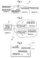
- Figure 1 is a diagram of a distributed media environment utilizing one receiver as a transmitter;
- Figure 2 is a diagram of a second embodiment distributed media environment utilizing a remote tuning control interface; and
- Figure 3 is a diagram of a receiver used in the media environment of Figure 1.
- Corresponding reference characters indicate corresponding parts throughout the several views. Although the drawings represent embodiments of the present invention, the drawings are not necessarily to scale and certain features may be exaggerated in order to better illustrate and explain the present invention. The exemplifications set out herein illustrate embodiments of the invention in several forms and such exemplification is not to be construed as limiting the scope of the invention in any manner.
- The embodiments discussed below are not intended to be exhaustive or limit the invention to the precise forms disclosed in the following detailed description. Rather, the embodiments are chosen and described so that others skilled in the art may utilize their teachings.
- As shown in Figure 1, a
distributed media system 10 includes a plurality of locations/regions A, B, C, D. Each region A, B, C, D includes at least onereceiver - As shown in Figure 3, each receiver 1-n includes
internal receiver 102 andcontroller 112 configured to receive a common media signal including content information and a control signal. The signal may be transmitted over VHF, UHF, or RF waves, over the internet (TCP/IP), over satellite communication such as satellite radio, or any other communication mode that provides for multiple distributed receivers to substantially simultaneously receive a common signal. Additionally, each receiver 1-n may optionally includeinterface 12 andtransmitter 100 that provide for at least partial control over the other remotely located receivers. Simultaneous reception of the common signal further allows simultaneous display of the content information contained within the signal. -
Interface 12 includes an input device such as a keyboard, touchpad, or any other input device known in the art.Interface 12 may be integrated with a receiver 1-n as in Figures 1 and 3, or may be a stand alone device in distributed media system 10' as shown in Figure 2. The input device allows a user to select a local receiver, if present, or any remote receiver. Once selected, the user may see the settings of the selected receiver and may then change the settings for the selected receiver via a controller signal. Alternatively,interface 12 may include functionality to allow a user to select all receivers or a plurality of receivers such that changes to the settings are implemented at all selected receivers via the controller signal. Such settings include picking an input to receive and any other function of the receiver. Accordingly,interface 12 allows both the remote selecting and the remote monitoring of the receivers 1-n.Interface 12 may include a webpage therein to guide a user through the local and remote controls. Furthermore, the embodiment ofinterface 12 as a stand alone device may be a PC with software thereon that allows the PC to control the receivers via an internet connection (TCP/IP) or otherwise. It should be appreciated that alternatively to having asingle interface 12 to control both local and remote settings, there may be oneinterface 12 to control local settings and asecond interface 12 to control remote settings. - Figure 1 shows
receiver 4 in region B acting as a source of the controller signal andreceivers local interface 12. In a commercial setting, certain regions may wish to switch away for a variety of reasons including the region not participating in a promotion being advertised on the common signal or the region having a unique promotion with its own unique media signal. Furthermore,remote control interface 12 includes a lockout function to prevent individuals at the regions from altering the settings. It should be appreciated that the media system may have a plurality of transmitters/sources that each receiver may locally or remotely choose to receive viacontrol interface 12. Accordingly, regions A-D can be placed in groups such that each group receives a different input. Such groupings can be useful when the media network spans multiple time zones and the commercial retailer's sales are at least partially time of day dependent, such as a restaurant. - Figure 2 shows another embodiment of the present invention including an
interface 12 and tworeceivers interface 12 may be a PC and may have a feature thereon that allows the remote receivers to be locked on the settings placed byinterface 12 of region A. In yet another alternative,interface 12 may include a wireless controller that interfaces with an antenna that is coupled to the internet. - While this invention has been described as having an exemplary design, the present invention may be further modified within the spirit and scope of this disclosure. This application is therefore intended to cover any variations, uses, or adaptations of the invention using its general principles. Further, this application is intended to cover such departures from the present disclosure as come within known or customary practice in the art to which this invention pertains.
Claims (20)
- In a distributed content display system (10) including a source of media content, a media unit (1) comprising:a receiver (102) for receiving content information from the source of media content and for receiving a controller signal; anda controller (112) for controlling the reception of the receiver (102) according to the controller signal.
- The media unit (1) of claim 1, further including a transmitter (100).
- The media unit (1) of claim 2, wherein the transmitter (100) transmits the control signal.
- The media unit (1) of claim 2, wherein the controller (112) is adapted to provide a controller signal via the transmitter (100).
- The media unit (1) of claim 4, wherein the controller (112) has software enabling selection of a remote media unit (2).
- The media unit (1) of claim 1, wherein the content information is an audio signal and the media unit (1) is configured to display the audio signal.
- The media unit (1) of claim 1, wherein the controller (112) has software enabling locking the media unit (1) to receive an input upon receipt of a predetermined control signal.
- A method of distributing a common content signal including the step of:providing a first receiver (1) and a second receiver (2), the first and second receivers (1, 2) configured to receive a control signal, the control signal designating the first receiver (1) and the second receiver (2) to receive the common signal from a first source.
- The method of claim 8, further including the step of providing a third receiver (3) that receives the control signal, the control signal designating the third receiver (3) to receive the common signal from a second source.
- The method of claim 8, further including the step of:providing a controller (112) at a location remote from the first and second receivers (1, 2), wherein the controller (112) generates the control signal.
- The method of claim 8, further including the step of:simultaneously displaying content of the content signal by the first and second receivers (1, 2).
- The method of claim 8, wherein the control signal is generated by a controller (112) within one of the first and second receivers (1, 2).
- A media device (1) including:a receiver (102) for receiving a media signal;a transmitter (100) for transmitting a controller signal to at least one remote site;a first controller (112) configured to select a receiving mode of the media device (1); anda second controller (112) configured to select a receiving mode of a media device (2) located at the at least one remote site.
- The device of claim 13, wherein the first and second controllers (112) utilize a common interface (12).
- The device of claim 13, wherein the transmitter (100) transmits the media signal via one method selected from the list including VHF, UHF, RF, microwave, satellite, and TCP/IP.
- The media device of claim 13, wherein the media device (1) is coupled to a second device (2) including a third controller (112), the third controller (112) being able to select receiving settings of the media device (1).
- A method of creating a uniform content environment including the steps of:providing a receiver (1, 2, 3, 4, n) at each of a plurality of remote sites, each of the receivers (1, 2, 3, 4, n) capable of performing a receiving function;obtaining a common content signal by each receiver (1, 2, 3, 4, n);obtaining a controller signal by each receiver (1, 2, 3, 4, n), the controller signal directing a first receiver (1) located at the first site to display the common content signal at the first site; and directing at least a second receiver (2) located at a second site to perform the receiving function to receive the common content signal and to display the common content signal such that the first and second sites substantially simultaneously display the common content signal.
- The method of claim 17, wherein the controller signal is generated by a controller (112) that is part of the first receiver.
- The method of claim 17, wherein the controller signal is generated by a controller (112) that is separate from the first receiver and separate from the second receiver.
- The method of claim 17, wherein the controller signal is generated by a controller (112) that is located at the second site.
Applications Claiming Priority (1)
| Application Number | Priority Date | Filing Date | Title |
|---|---|---|---|
| US11/081,458 US20060210086A1 (en) | 2005-03-16 | 2005-03-16 | Real-time synchronous multi-regional distributed media environment system |
Publications (1)
| Publication Number | Publication Date |
|---|---|
| EP1705861A1 true EP1705861A1 (en) | 2006-09-27 |
Family
ID=36440974
Family Applications (1)
| Application Number | Title | Priority Date | Filing Date |
|---|---|---|---|
| EP06075493A Withdrawn EP1705861A1 (en) | 2005-03-16 | 2006-03-03 | Real-time synchronous multi-regional distributed media environment system |
Country Status (2)
| Country | Link |
|---|---|
| US (1) | US20060210086A1 (en) |
| EP (1) | EP1705861A1 (en) |
Citations (2)
| Publication number | Priority date | Publication date | Assignee | Title |
|---|---|---|---|---|
| WO2001057763A1 (en) * | 2000-02-01 | 2001-08-09 | Michael Richard Oplinger | Method and system for displaying digital billboards |
| WO2002101701A2 (en) * | 2001-06-12 | 2002-12-19 | Kent Ridge Digital Labs | Smart interactive billboard device |
Family Cites Families (1)
| Publication number | Priority date | Publication date | Assignee | Title |
|---|---|---|---|---|
| US6961555B1 (en) * | 1998-09-11 | 2005-11-01 | L.V. Partners, L.P. | System and apparatus for connecting a wireless device to a remote location on a network |
-
2005
- 2005-03-16 US US11/081,458 patent/US20060210086A1/en not_active Abandoned
-
2006
- 2006-03-03 EP EP06075493A patent/EP1705861A1/en not_active Withdrawn
Patent Citations (2)
| Publication number | Priority date | Publication date | Assignee | Title |
|---|---|---|---|---|
| WO2001057763A1 (en) * | 2000-02-01 | 2001-08-09 | Michael Richard Oplinger | Method and system for displaying digital billboards |
| WO2002101701A2 (en) * | 2001-06-12 | 2002-12-19 | Kent Ridge Digital Labs | Smart interactive billboard device |
Also Published As
| Publication number | Publication date |
|---|---|
| US20060210086A1 (en) | 2006-09-21 |
Similar Documents
| Publication | Publication Date | Title |
|---|---|---|
| CN102047655B (en) | Booking control apparatus, booking execution apparatus, booking control system and booking control method | |
| KR101984570B1 (en) | Digital signage system and method of controlling thereof | |
| US20130057395A1 (en) | Remote control, remote control system, and remote control method | |
| US11159853B2 (en) | Mobile terminal and video display apparatus | |
| JP4881503B2 (en) | Command processing method and wireless communication device | |
| TW201138487A (en) | Audio monitoring system | |
| CN109155872A (en) | Information processing equipment, television receiver, information processing system and message handling program | |
| US10079930B2 (en) | Information processing apparatus, information processing system, and information processing method | |
| CN103123471A (en) | Remote control system and method | |
| US20060210086A1 (en) | Real-time synchronous multi-regional distributed media environment system | |
| EP1451938A1 (en) | Remote programming of radio preset stations over a network | |
| KR20160103776A (en) | Recommendation stock service system and recommendation stock service method using the system | |
| US7051283B2 (en) | Portable electronic apparatus and method for providing visual and/or audio information | |
| JP5105211B2 (en) | Wireless LAN system | |
| JP2009294579A (en) | Voice output device, system, and method | |
| JP2005167573A (en) | Image display system and image display method | |
| KR20090074857A (en) | Control device and method for commercial video display equipment | |
| JP2005277802A (en) | Control method of remote control apparatus, control method of apparatus to be controlled, remote control apparatus, apparatus to be controlled, and program | |
| KR19990064703A (en) | Display apparatus and method for advertising information using a Internet | |
| JP2002112229A (en) | Television broadcasting system | |
| WO2013121612A1 (en) | Broadcast receiving apparatus system, frequency table creating method, and broadcast receiving apparatus | |
| KR200313065Y1 (en) | System for advertisement broadcasting of a vending machine | |
| JP2004096529A (en) | Information processing apparatus, information processing method, and program | |
| KR101873986B1 (en) | A remote controlling apparatus and the method of operating thereof | |
| US8296795B2 (en) | Method for tuning to channel and broadcast receiving apparatus using the same |
Legal Events
| Date | Code | Title | Description |
|---|---|---|---|
| PUAI | Public reference made under article 153(3) epc to a published international application that has entered the european phase |
Free format text: ORIGINAL CODE: 0009012 |
|
| AK | Designated contracting states |
Kind code of ref document: A1 Designated state(s): AT BE BG CH CY CZ DE DK EE ES FI FR GB GR HU IE IS IT LI LT LU LV MC NL PL PT RO SE SI SK TR |
|
| AX | Request for extension of the european patent |
Extension state: AL BA HR MK YU |
|
| 17P | Request for examination filed |
Effective date: 20070327 |
|
| AKX | Designation fees paid |
Designated state(s): AT BE BG CH CY CZ DE DK EE ES FI FR GB GR HU IE IS IT LI LT LU LV MC NL PL PT RO SE SI SK TR |
|
| 17Q | First examination report despatched |
Effective date: 20070611 |
|
| STAA | Information on the status of an ep patent application or granted ep patent |
Free format text: STATUS: THE APPLICATION IS DEEMED TO BE WITHDRAWN |
|
| 18D | Application deemed to be withdrawn |
Effective date: 20111001 |