EP1705783A1 - Generator and electric generating system - Google Patents
Generator and electric generating system Download PDFInfo
- Publication number
- EP1705783A1 EP1705783A1 EP06003405A EP06003405A EP1705783A1 EP 1705783 A1 EP1705783 A1 EP 1705783A1 EP 06003405 A EP06003405 A EP 06003405A EP 06003405 A EP06003405 A EP 06003405A EP 1705783 A1 EP1705783 A1 EP 1705783A1
- Authority
- EP
- European Patent Office
- Prior art keywords
- permanent magnet
- rotor
- generator
- stator
- seating
- Prior art date
- Legal status (The legal status is an assumption and is not a legal conclusion. Google has not performed a legal analysis and makes no representation as to the accuracy of the status listed.)
- Granted
Links
Images





Classifications
-
- H—ELECTRICITY
- H02—GENERATION; CONVERSION OR DISTRIBUTION OF ELECTRIC POWER
- H02K—DYNAMO-ELECTRIC MACHINES
- H02K1/00—Details of the magnetic circuit
- H02K1/06—Details of the magnetic circuit characterised by the shape, form or construction
- H02K1/22—Rotating parts of the magnetic circuit
- H02K1/27—Rotor cores with permanent magnets
- H02K1/2706—Inner rotors
- H02K1/272—Inner rotors the magnetisation axis of the magnets being perpendicular to the rotor axis
- H02K1/274—Inner rotors the magnetisation axis of the magnets being perpendicular to the rotor axis the rotor consisting of two or more circumferentially positioned magnets
- H02K1/2753—Inner rotors the magnetisation axis of the magnets being perpendicular to the rotor axis the rotor consisting of two or more circumferentially positioned magnets the rotor consisting of magnets or groups of magnets arranged with alternating polarity
- H02K1/276—Magnets embedded in the magnetic core, e.g. interior permanent magnets [IPM]
-
- H—ELECTRICITY
- H02—GENERATION; CONVERSION OR DISTRIBUTION OF ELECTRIC POWER
- H02K—DYNAMO-ELECTRIC MACHINES
- H02K1/00—Details of the magnetic circuit
- H02K1/06—Details of the magnetic circuit characterised by the shape, form or construction
- H02K1/22—Rotating parts of the magnetic circuit
- H02K1/24—Rotor cores with salient poles ; Variable reluctance rotors
-
- H—ELECTRICITY
- H02—GENERATION; CONVERSION OR DISTRIBUTION OF ELECTRIC POWER
- H02K—DYNAMO-ELECTRIC MACHINES
- H02K21/00—Synchronous motors having permanent magnets; Synchronous generators having permanent magnets
- H02K21/12—Synchronous motors having permanent magnets; Synchronous generators having permanent magnets with stationary armatures and rotating magnets
- H02K21/14—Synchronous motors having permanent magnets; Synchronous generators having permanent magnets with stationary armatures and rotating magnets with magnets rotating within the armatures
Definitions
- This invention relates to a generator employing permanent magnets for its excitation.
- the object of the invention is to provide a generator easy to assemble even if there is an obstacle such as a turbine in the axial direction of the rotor of the generator.
- a feature of this invention is a generator which is provide with a rotor having a permanent magnet placed between a seating and a pole shoe.
- Another feature of this invention is a generator which is provide with the above-mentioned permanent magnet of which width is greater than that of the seating.
- Still another feature of this invention is a generator which is provide with a rotor having permanent magnets and being supported to be rotatable, and a stator having field windings wound on it, wherein the rotor is provided with seatings for supporting the permanent magnets, and the radius of the pole shoe arc part is smaller than that of the rotor.
- Yet another feature of this invention is a generator which is provide with a rotor having permanent magnets and being supported to be rotatable, and a stator having field windings wound on it, wherein the stator is so constructed in portions that the number of stator portions equals that of the parallel circuits in the field windings wound on the stator.
- a permanent magnet is placed between a seating and a pole shoe, thus it is possible to provide a generator and/or an electric generating system which is easily assembled.
- FIG 10 to explain the effects of the invention, a comparative example of a turbine generator having a brushless excitation system is shown.
- the turbine generator has an alternating-current exciter 4 and a sub-exciter 5 both in the overhang part located at an end of its rotor shaft 1.
- the sub-exciter 5 has a permanent magnet 13 in the rotor poles, and the permanent magnet 13 produces magnetic fields at right angles to armature windings 8 of the sub-exciter.
- a rotational force is applied by the turbine through a coupling 3, thus the rotor shaft is rotated.
- the armature coils 8 of the sub-exciter 5 has an alternating current I a1 induced in them owing to electromagnetic induction.
- An auto voltage regulator 16 capable of rectification detects the voltage of the generator, changes this alternating current I a1 into a direct current I d1 , and supplies it to the field coils 18 of the alternating-current exciter 4.
- the armature coils 19 of the alternating-current exciter 4 are placed on the rotor 20 of the alternating-current exciter 4, thus the rotation of the rotor shaft 1 induces an alternating current I a2 in the armature coils 19.
- the alternating current I a2 is converted into a direct current through a rotating rectifier 17, and is supplied to turbine generator field coils 22.
- the rotation of the rotor shaft 1 induces an alternating current in turbine generator armature coils 21, making it possible to supply electric power outwards.
- FIG 11 an example of a circuit diagram showing a comparative example of a brushless excitation system.
- the magnitude of the alternating voltage arising from a sub-exciter 1201 is regulated by an auto voltage regulator 1203.
- This alternating voltage is converted by a rectifier into a direct voltage, resulting in a direct current flow on the output side of the sub-exciter 1201.
- This direct current gives off direct current magnetic fields, the electromagnetic induction of which produces an alternating current in an alternating-current exciter 1202 of a rotating part 1205.
- This alternating current is converted by the rectifier of the rotating part into a direct current, which is then supplied to the field coils of the rotating part.
- the overhang part has the sub-exciter 4 and the alternating-current exciter 5, which results in the problem of the overhang part being long.
- a sub-exciter 5 is installed using the space between a coupling 3 and a rotor shaft 1 of the generator.
- the sub-exciter installed in the overhang part in the comparative example is absent from the overhang part, thus it is possible to shorten the overhang part of the rotor shaft 1.
- the seating 1104 is made, of a magnetic material, is placed in the inward radius direction of the permanent magnet 1102 (toward the rotor shaft), and supports the permanent magnet 1102.
- the pole shoe 1109 is placed in the outward direction of the permanent magnet 1102, and is made of a magnetic material.
- the numeral 1106 represents a stator, and 1107 a rotor carried so as to be rotatable.
- the stator 1106 has coils 1105 wound on it, and the rotor 1107 has the permanent magnet 1102 placed on it.
- the rotation of the rotor 1107 in the circumferential direction 1108 allows the magnetic flux produced by the permanent magnet 1102 to cross the coils 1105 and thereby a voltage to occur in the coils 1105 owing to electromagnetic induction.
- the pole shoe 1109 and a rotor 1107 are secured together with a bolt or a binding, but it is understood that the pole shoe 1109, the permanent magnet 1102, and the seating 1104 and the rotor 1107 may be fixed solidly with a bolt.
- the pole shoe 1109, the permanent magnet 1102 and the seating 1104 are rectangular in shape radially, but it is understood that their shape may be circular or elliptic in order to raise their mechanical strength.
- the width Wm in the circumferential direction of the permanent magnet 13 is greater than the width Wb in the circumferential direction of a seating 24.
- the magnetic flux given off by an end of a permanent magnet 13 goes beside the permanent magnet 13 and enters the seating 24 by way of a path 32, whose magnetic resistance is so great that there are hardly any fluxes going on this path, and that it is possible to reduce flux leakage.
- Figure 1 shows a circumferential section of a part of a gererator pole placed in a generator in this embodiment.
- the seating 24 for placing the permanent magnet 13.
- the seating 24 is formed uniformly with the rotor shaft 1 by machining or formed separately out of a magnetic material, and is located on the rotor shaft 1.
- the permanent magnet 13 is covered with a cover 14 made of a non-magnetic material in order to prevent scattering.
- the distance Wm in the circumferential direction of the permanent magnet 13 is greater than the distance Wb in the circumferential direction of the seating 24, thus a pole shoe 12 is farther apart so as to prevent the flux leakage from the pole shoe 12 to the seating 24. This prevents generated voltage from reducing.
- Figure 2 is a axial sectional view of a part of a generator pole placed in a generator in this embodiment.
- the length Wm in the axial direction of the permanent magnet 13 is greater than the length Wb in the axial direction of the seating 24, thus the flux leakage from the pole shoe 12 to the seating 24 is prevented.
- Figure 3 shows a third embodiment of this invention. It shows a circumferential section of a part of a pole of the sub-exciter mounted in a turbine generator according to this invention.
- a permanent magnet 13 between the rotor shaft 1 and a pole shoe 12, the permanent magnet being covered with a cover 14 made of a non-magnetic material in order to prevent scattering.
- the cover 14 has a convex part on it, and the pole shoe 12 a concave part. Fitting these convex part and concave part into each other on placing the magnet allows the permanent magnet 13 to be held during rotation, and also allows the positioning in the circumferential direction of the permanent magnet 13 and the pole shoe 12 to be easier on assembling and disassembling them.
- Both of the pole shoe 12 and the seating 24 have a concave part 25, respectively which is not fitted on the convex part of the covering 14, thus the disassembly of the permanent magnet 13 is made easier.
- convex and concave parts are represented by rectangles, but they may take shapes whose section is triangular or circular.
- Figure 4 shows a fourth embodiment of this invention. It shows a circumferential section of a part of a pole placed in a generator in this embodiment.
- a permanent magnet 13 between a rotor shaft 1 and a pole shoe 12, the permanent magnet being covered with a cover 14 made of a non-magnetic material in order to prevent scattering.
- the permanent magnet 13 has a convex part, and a seating 24 has a concave part. Fitting these convex part and concave part into each other on placing the magnet allows the permanent magnet 13 to be held during rotation, and also to be assembled and disassembled with more ease.
- Both of the pole shoe 12 and the seating 24 have a concave part 25, respectively which is not fitted on the convex part of the covering 14, thus the disassembly of the permanent magnet 13 is made easier.
- the concave part 25 has only to be picked with a nail.
- convex and concave parts are represented by rectangles, but they may take shapes whose section is triangular or circular.
- Figures 5 and 6 show a fifth embodiment of this invention.
- Figure 5 shows a circumferential section of a part of a generator pole placed in a generator in this embodiment.
- the pole shoe 12 has its concave parts, which in the fifth embodiment are in contact with the permanent magnet 13, brought circumferentially to the edges, and has its overall circumferential section made convex, with the result that the length Wm in the circumferential direction of the permanent magnet 13 is greater than the length Wp in the circumferential direction of the convex part of the pole shoe 12.
- This pole shoe 12 with the concave parts is fitted into convex parts formed in a cover 14 to hold the permanent magnet 13 and to have the pole shoe 12 and a seating 24 located far from each other so as to reduce the flux leakage from the pole shoe 12 to the seating 24 and to prevent the generated voltage of the generator from falling.
- Figure 6 is a axial sectional view of a part of a generator pole placed in a generator in this embodiment.
- the pole shoe 12 has its concave parts, which are in contact with the permanent magnet 13, brought axially to the edges and has its overall axial section made convex, with the result that the length Wm' in the axial direction of the permanent magnet 13 is greater than the length Wp in the axial direction of the convex part of the pole shoe 12. This allows the pole shoe 12 and a seating 24 to be located far from each other to reduce the flux leakage from the pole shoe 12 to the seating 24 and prevents the generated voltage of the generator from falling.
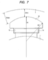
- Figure 7 shows a sixth embodiment of this invention. It shows a circumferential section of a part of a generator pole placed in a turbine generator of this invention.
- the radius R2 of the arc part of a pole shoe 12 is smaller than the radius R1 of the rotor 1, thus the outer edge of the rotor 1 and the inner surface of the stator 7 have their maximum gap Gmax and their minimum gap Gmin the ratio Gmax/Gmin of which is given as 1.33 or more.
- Figure 8 is a graphs a result of assuming that Gmin is 10 mm and then analyzing the relation between Gmax/Gmin and the distortion factor of a voltage induced in the windings of the armature of the generator. Judging from Figure 8, giving Gmax/Gmin as 1.2 or more allows the voltage distortion factor to remarkably fall, and giving Gmax/Gmin as 1.33 or more allows the voltage distortion factor to be as small as 5 percent or less.
- Figure 9 shows a vertical sectional view of the seventh embodiment of this invention. It shows a generator in this embodiment, detailedly a single-phase, two-parallel-circuit stator. Slots 11 contain coils C1 to C24 wound on each tooth 10, respectively. Series winding is applied to coils C1 to C12. Coils not having a tooth in between, for example, C2 and C3, are connected to each other on an overhead part. In the same way, coils C13 to C24 have series winding applied to them. The joints of the windings are only at the single location between C1 and C24 so as to facilitate the jointing of wires and the assembly and disassembly of parts.
- dividing the stator into two divisions and providing two parallel circuits allows the stator, while kept parted and after each set of parallel-circuit coils is wound on each parted stator, to be assembled.
- the effect of this embodiment can be obtained by giving the coils as concentrated windings and by giving the number of the phases multiplied by that of the parallel circuits equals to number of the stator divisions.
- the iron core 26 of the stator 7 has core parts 27 each of which is located between two slots not having a tooth 10 in between and that two of them are divided along lines a-a' and b-b'. Designating core parts 27 as these divisions allows the windings to be kept intact when parting them. This makes it possible to assemble and disassemble the stator of a sub-exciter 5 without its coils and insulators being damaged by such accidents as hitting.
- Figures 14 and 15 show an eighth embodiment of this invention.
- Figure 14 is a circumferential sectional view of a part of a generator pole in this embodiment, and Figure 15 a vertical sectional view of it, where between a seating 1424 mounted on a rotor shaft 1401 and a circular-cone-shaped pole shoe 1412 there is inserted a ring-shaped permanent magnet 1413.
- the pole shoe 1412 has an end-enlarged hole formed radially-centered so as to be secured by a non-magnetic bolt 1426.
- the permanent magnet 1413 also has a hole formed radially-centered so as to receive the non-magnetic bolt 1426.
- the non-magnetic bolt 1426 is fastened into the tapped holes formed in the rotor shaft 1401 and the seating 1424 so as to secure the pole shoe 1412 and the permanent magnet 1413 together.
- Using a plurality of bolts to keep the pole shoe 1412 and the permanent magnet 1413 in place has a possibility that a certain bolt has their load biased toward it and that the bolt itself or its hole breaks.
- one non-magnetic bolt 1426 is used to secure the pole shoe 1412 and the permanent magnet 1413 together, thus such an imbalance of load can be avoided.
- a pole shoe and a permanent magnet which have a rectangular horizontal section leads to a pronounced warping up at a corner of the rectangle far from the location of fixing.
- a pole shoe radially having a uniform thickness leads to a pronounced warping up at its ends during assembly or during operation.
Landscapes
- Engineering & Computer Science (AREA)
- Power Engineering (AREA)
- Iron Core Of Rotating Electric Machines (AREA)
- Synchronous Machinery (AREA)
- Permanent Field Magnets Of Synchronous Machinery (AREA)
Abstract
Description
- This invention relates to a generator employing permanent magnets for its excitation.
- An example of a conventional generator having field permanent magnets inserted into slots is described in the official gazette,
Japanese Application Patent Laid-Open Publication No. Hei 05-146103 - [Patent Document 1]
Japanese Application Patent Laid-Open Publication No. Hei 05-146103 - With such a generator employing permanent magnets for its magnetic field as described in
Patent Document 1 above, it is inevitable that the permanent magnets need to be inserted into its rotor of the generator in the axial direction. In this case, there is an obstacle such as a turbine for the electric generating system in the axial direction of the rotor of the generator, the problem arises that it is difficult to insert permanent magnets to the generator. - The object of the invention is to provide a generator easy to assemble even if there is an obstacle such as a turbine in the axial direction of the rotor of the generator.
- A feature of this invention is a generator which is provide with a rotor having a permanent magnet placed between a seating and a pole shoe.
- Another feature of this invention is a generator which is provide with the above-mentioned permanent magnet of which width is greater than that of the seating.
- Still another feature of this invention is a generator which is provide with a rotor having permanent magnets and being supported to be rotatable, and a stator having field windings wound on it, wherein the rotor is provided with seatings for supporting the permanent magnets, and the radius of the pole shoe arc part is smaller than that of the rotor.
- Yet another feature of this invention is a generator which is provide with a rotor having permanent magnets and being supported to be rotatable, and a stator having field windings wound on it, wherein the stator is so constructed in portions that the number of stator portions equals that of the parallel circuits in the field windings wound on the stator.
- Further features of this invention will be described in the Preferable Embodiments of the Invention section.
- According to the present invention, a permanent magnet is placed between a seating and a pole shoe, thus it is possible to provide a generator and/or an electric generating system which is easily assembled.
-
- Figure 1 is a sectional view in the circumferential direction of a part of the generator in the second embodiment of this invention.
- Figure 2 is a sectional view in the axial direction of a part of the generator in the second embodiment of this invention.
- Figure 3 is a sectional view of in the circumferential direction of a part of the generator in the third embodiment of this invention.
- Figure 4 is a sectional view in the circumferential direction of a part of the generator in the fourth embodiment of this invention.
- Figure 5 is a sectional view in the circumferential direction of a part of the generator in the fifth embodiment of this invention.
- Figure 6 is a sectional view in the axial direction of a part of the generator in the fifth embodiment of this invention.
- Figure 7 is a sectional view in the circumferential direction of a part of the generator in the sixth embodiment of this invention.
- Figure 8 is a graph showing the relation between Gmax/Gmin and the distortion factor in a sixth embodiment of this invention.
- Figure 9 is a vertical sectional view of the stator in the seventh embodiment of this invention.
- Figure 10 is a sectional view of a comparative example of a turbine generator.
- Figure 11 is a diagram showing the circuit in a comparative example of a turbine generator.
- Figure 12 is a sectional view of the turbine generating system in the first embodiment of this invention.
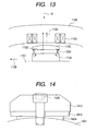
- Figure 13 is a sectional view in the circumferential direction of a part of the generator in the first embodiment of this invention.
- Figure 14 is a sectional view in the circumferential direction of a part of the generator in the eighth embodiment of this invention.
- Figure 15 is a sectional view in the vertical direction of a part of the generator in the eighth embodiment of this invention.
- In Figure 10, to explain the effects of the invention, a comparative example of a turbine generator having a brushless excitation system is shown. The turbine generator has an alternating-current exciter 4 and a
sub-exciter 5 both in the overhang part located at an end of itsrotor shaft 1. Thesub-exciter 5 has apermanent magnet 13 in the rotor poles, and thepermanent magnet 13 produces magnetic fields at right angles toarmature windings 8 of the sub-exciter. - On the other hand, to a
rotor shaft 1, a rotational force is applied by the turbine through acoupling 3, thus the rotor shaft is rotated. In this way, the armature coils 8 of thesub-exciter 5 has an alternating current Ia1 induced in them owing to electromagnetic induction. Anauto voltage regulator 16 capable of rectification detects the voltage of the generator, changes this alternating current Ia1 into a direct current Id1, and supplies it to thefield coils 18 of the alternating-current exciter 4. - The
armature coils 19 of the alternating-current exciter 4 are placed on therotor 20 of the alternating-current exciter 4, thus the rotation of therotor shaft 1 induces an alternating current Ia2 in thearmature coils 19. The alternating current Ia2 is converted into a direct current through a rotatingrectifier 17, and is supplied to turbinegenerator field coils 22. The rotation of therotor shaft 1 induces an alternating current in turbinegenerator armature coils 21, making it possible to supply electric power outwards. - In Figure 11, an example of a circuit diagram showing a comparative example of a brushless excitation system. The magnitude of the alternating voltage arising from a
sub-exciter 1201 is regulated by anauto voltage regulator 1203. This alternating voltage is converted by a rectifier into a direct voltage, resulting in a direct current flow on the output side of thesub-exciter 1201. This direct current gives off direct current magnetic fields, the electromagnetic induction of which produces an alternating current in an alternating-current exciter 1202 of arotating part 1205. This alternating current is converted by the rectifier of the rotating part into a direct current, which is then supplied to the field coils of the rotating part. - When the rotating part rotates owing to the mechanical force of the turbine, the electromagnetic induction of the magnetic field given off by the direct current made to flow in the field coils gives rise to an alternating voltage in the armature windings on the side of the turbine generator stator (not shown in the figure). In the construction shown in Figure 10, the overhang part has the sub-exciter 4 and the alternating-
current exciter 5, which results in the problem of the overhang part being long. - In the first embodiment of this invention, therefore, as shown in Figure 12, using the space between a
coupling 3 and arotor shaft 1 of the generator, asub-exciter 5 is installed. According to this embodiment, the sub-exciter installed in the overhang part in the comparative example is absent from the overhang part, thus it is possible to shorten the overhang part of therotor shaft 1. - Here, if the rotor of the
sub-exciter 5 is, as shown inPatent Document 1, so constructed that a magnet is inserted into a slot, it turns out that the magnet needs to be inserted in the direction represented by anarrow 23, but thecoupling 3 obstructs the insertion of the magnet. This is why in the embodiment, as shown in Figure 13, apermanent magnet 1102 is sandwiched by apole shoe 1109 and aseating 1104 fitting thepermanent magnet 1102. This construction allows thepermanent magnet 1102 to be placed on theseating 1104 in theradial direction 31, thus even if a presence such as a turbine in the axial direction of the rotor shaft makes it impossible to insert a permanent magnet in the axial direction, a generator for excitation can be installed. - A more detailed description will be given of the construction shown in Figure 13. The
seating 1104 is made, of a magnetic material, is placed in the inward radius direction of the permanent magnet 1102 (toward the rotor shaft), and supports thepermanent magnet 1102. Thepole shoe 1109 is placed in the outward direction of thepermanent magnet 1102, and is made of a magnetic material. Thenumeral 1106 represents a stator, and 1107 a rotor carried so as to be rotatable. Thestator 1106 hascoils 1105 wound on it, and therotor 1107 has thepermanent magnet 1102 placed on it. The rotation of therotor 1107 in the circumferential direction 1108 allows the magnetic flux produced by thepermanent magnet 1102 to cross thecoils 1105 and thereby a voltage to occur in thecoils 1105 owing to electromagnetic induction. - In this embodiment, the
pole shoe 1109 and arotor 1107 are secured together with a bolt or a binding, but it is understood that thepole shoe 1109, thepermanent magnet 1102, and theseating 1104 and therotor 1107 may be fixed solidly with a bolt. And in this embodiment thepole shoe 1109, thepermanent magnet 1102 and theseating 1104 are rectangular in shape radially, but it is understood that their shape may be circular or elliptic in order to raise their mechanical strength. - In this embodiment, there is a big advantage that a generator can easily be assembled. However, the problem arises that, among the magnetic fluxes given off by the
permanent magnet 1102, amagnetic flux 1103 passes effectively thestator 1106, but amagnetic flux 1204 given off by an end of thepermanent magnet 1102 goes beside thepermanent magnet 1102, and without passing thestator 1106 returns to thepermanent magnet 1102, ending up being ineffective for electric generating. - In a second embodiment, therefore, as shown in Figures 1 and 2, the width Wm in the circumferential direction of the
permanent magnet 13 is greater than the width Wb in the circumferential direction of aseating 24. According to this construction, the magnetic flux given off by an end of apermanent magnet 13 goes beside thepermanent magnet 13 and enters theseating 24 by way of apath 32, whose magnetic resistance is so great that there are hardly any fluxes going on this path, and that it is possible to reduce flux leakage. With reference to Figures 1 and 2, a more detailed description will be given of the second embodiments of this invention. - Figure 1 shows a circumferential section of a part of a gererator pole placed in a generator in this embodiment. On a
rotor shaft 1 in any given circumferential position is mounted theseating 24 for placing thepermanent magnet 13. Theseating 24 is formed uniformly with therotor shaft 1 by machining or formed separately out of a magnetic material, and is located on therotor shaft 1. Thepermanent magnet 13 is covered with acover 14 made of a non-magnetic material in order to prevent scattering. The distance Wm in the circumferential direction of thepermanent magnet 13 is greater than the distance Wb in the circumferential direction of theseating 24, thus apole shoe 12 is farther apart so as to prevent the flux leakage from thepole shoe 12 to theseating 24. This prevents generated voltage from reducing. - Figure 2 is a axial sectional view of a part of a generator pole placed in a generator in this embodiment. The length Wm in the axial direction of the
permanent magnet 13 is greater than the length Wb in the axial direction of theseating 24, thus the flux leakage from thepole shoe 12 to theseating 24 is prevented. - Figure 3 shows a third embodiment of this invention. It shows a circumferential section of a part of a pole of the sub-exciter mounted in a turbine generator according to this invention. There is placed a
permanent magnet 13 between therotor shaft 1 and apole shoe 12, the permanent magnet being covered with acover 14 made of a non-magnetic material in order to prevent scattering. Thecover 14 has a convex part on it, and the pole shoe 12 a concave part. Fitting these convex part and concave part into each other on placing the magnet allows thepermanent magnet 13 to be held during rotation, and also allows the positioning in the circumferential direction of thepermanent magnet 13 and thepole shoe 12 to be easier on assembling and disassembling them. - Both of the
pole shoe 12 and theseating 24 have aconcave part 25, respectively which is not fitted on the convex part of the covering 14, thus the disassembly of thepermanent magnet 13 is made easier. - Note that in the figures the convex and concave parts are represented by rectangles, but they may take shapes whose section is triangular or circular.
- Figure 4 shows a fourth embodiment of this invention. It shows a circumferential section of a part of a pole placed in a generator in this embodiment. There is placed a
permanent magnet 13 between arotor shaft 1 and apole shoe 12, the permanent magnet being covered with acover 14 made of a non-magnetic material in order to prevent scattering. In addition to the convex parts of thecover 14 and the concave parts of thepole shoe 12 shown in reference toEmbodiment 3, thepermanent magnet 13 has a convex part, and aseating 24 has a concave part. Fitting these convex part and concave part into each other on placing the magnet allows thepermanent magnet 13 to be held during rotation, and also to be assembled and disassembled with more ease. - Both of the
pole shoe 12 and theseating 24 have aconcave part 25, respectively which is not fitted on the convex part of the covering 14, thus the disassembly of thepermanent magnet 13 is made easier. To remove thepole shoe 12 from thepermanent magnet 13 during maintenance, theconcave part 25 has only to be picked with a nail. - Note that in the figures the convex and concave parts are represented by rectangles, but they may take shapes whose section is triangular or circular.
- Figures 5 and 6 show a fifth embodiment of this invention. Figure 5 shows a circumferential section of a part of a generator pole placed in a generator in this embodiment. The
pole shoe 12 has its concave parts, which in the fifth embodiment are in contact with thepermanent magnet 13, brought circumferentially to the edges, and has its overall circumferential section made convex, with the result that the length Wm in the circumferential direction of thepermanent magnet 13 is greater than the length Wp in the circumferential direction of the convex part of thepole shoe 12. Thispole shoe 12 with the concave parts is fitted into convex parts formed in acover 14 to hold thepermanent magnet 13 and to have thepole shoe 12 and aseating 24 located far from each other so as to reduce the flux leakage from thepole shoe 12 to theseating 24 and to prevent the generated voltage of the generator from falling. - Figure 6 is a axial sectional view of a part of a generator pole placed in a generator in this embodiment. The
pole shoe 12 has its concave parts, which are in contact with thepermanent magnet 13, brought axially to the edges and has its overall axial section made convex, with the result that the length Wm' in the axial direction of thepermanent magnet 13 is greater than the length Wp in the axial direction of the convex part of thepole shoe 12. This allows thepole shoe 12 and aseating 24 to be located far from each other to reduce the flux leakage from thepole shoe 12 to theseating 24 and prevents the generated voltage of the generator from falling. - Figure 7 shows a sixth embodiment of this invention. It shows a circumferential section of a part of a generator pole placed in a turbine generator of this invention. The radius R2 of the arc part of a
pole shoe 12 is smaller than the radius R1 of therotor 1, thus the outer edge of therotor 1 and the inner surface of thestator 7 have their maximum gap Gmax and their minimum gap Gmin the ratio Gmax/Gmin of which is given as 1.33 or more. - Figure 8 is a graphs a result of assuming that Gmin is 10 mm and then analyzing the relation between Gmax/Gmin and the distortion factor of a voltage induced in the windings of the armature of the generator. Judging from Figure 8, giving Gmax/Gmin as 1.2 or more allows the voltage distortion factor to remarkably fall, and giving Gmax/Gmin as 1.33 or more allows the voltage distortion factor to be as small as 5 percent or less.
- Figure 9 shows a vertical sectional view of the seventh embodiment of this invention. It shows a generator in this embodiment, detailedly a single-phase, two-parallel-circuit stator.
Slots 11 contain coils C1 to C24 wound on eachtooth 10, respectively. Series winding is applied to coils C1 to C12. Coils not having a tooth in between, for example, C2 and C3, are connected to each other on an overhead part. In the same way, coils C13 to C24 have series winding applied to them. The joints of the windings are only at the single location between C1 and C24 so as to facilitate the jointing of wires and the assembly and disassembly of parts. - According to this embodiment, dividing the stator into two divisions and providing two parallel circuits allows the stator, while kept parted and after each set of parallel-circuit coils is wound on each parted stator, to be assembled. The effect of this embodiment can be obtained by giving the coils as concentrated windings and by giving the number of the phases multiplied by that of the parallel circuits equals to number of the stator divisions.
- Note that the
iron core 26 of thestator 7 hascore parts 27 each of which is located between two slots not having atooth 10 in between and that two of them are divided along lines a-a' and b-b'. Designatingcore parts 27 as these divisions allows the windings to be kept intact when parting them. This makes it possible to assemble and disassemble the stator of asub-exciter 5 without its coils and insulators being damaged by such accidents as hitting. - Figures 14 and 15 show an eighth embodiment of this invention. Figure 14 is a circumferential sectional view of a part of a generator pole in this embodiment, and Figure 15 a vertical sectional view of it, where between a
seating 1424 mounted on arotor shaft 1401 and a circular-cone-shapedpole shoe 1412 there is inserted a ring-shapedpermanent magnet 1413. Thepole shoe 1412 has an end-enlarged hole formed radially-centered so as to be secured by anon-magnetic bolt 1426. And thepermanent magnet 1413 also has a hole formed radially-centered so as to receive thenon-magnetic bolt 1426. Thenon-magnetic bolt 1426 is fastened into the tapped holes formed in therotor shaft 1401 and theseating 1424 so as to secure thepole shoe 1412 and thepermanent magnet 1413 together. - Using a plurality of bolts to keep the
pole shoe 1412 and thepermanent magnet 1413 in place has a possibility that a certain bolt has their load biased toward it and that the bolt itself or its hole breaks. In this embodiment, onenon-magnetic bolt 1426 is used to secure thepole shoe 1412 and thepermanent magnet 1413 together, thus such an imbalance of load can be avoided. - Note that using one bolt to secure a pole shoe and a permanent magnet which have a rectangular horizontal section leads to a pronounced warping up at a corner of the rectangle far from the location of fixing. In addition, a pole shoe radially having a uniform thickness leads to a pronounced warping up at its ends during assembly or during operation. In this embodiment, to prevent these, there are a circular-cone-shaped
pole shoe 1412 and a ring-shapedpermanent magnet 1413. This can prevent excessive warping up at ends. - Features, components and specific details of the structures of the above-described embodiments may be exchanged or combined to form further embodiments optimized for the respective application. As far as those modifications are readily apparent for an expert skilled in the art they shall be disclosed implicitly by the above description without specifying explicitly every possible combination, for the sake of conciseness of the present description.
Claims (14)
- A generator comprising:a rotor (20; 1107; 1401) having a permanent magnet (13; 1102; 1413) placed therein and supported to be rotatable, and a stator (7; 1106) having a field coil (C1-C24; 1105) wound thereon, characterized in thatthe rotor (20; 1107; 1401) is provided with a seating (24; 1104; 1424) made of a magnetic material for supporting the permanent magnet (13; 1102; 1413) and a pole shoe (12; 1109; 1412) made of a magnetic material placed in the outward radial direction (31) of the permanent magnet (13; 1102; 1413).
- A generator according to claim 1,
further characterized in that
the width in the circumferential direction (1108) of the permanent magnet (13; 1102; 1413) is greater than that of the seating (24; 1104; 1424). - A generator according to one of the preceding claims,
further characterized in that
the width in the axial direction of the permanent magnet (13; 1102; 1413) is greater than that of the seating (24; 1104; 1424). - A generator according to one of the precedings claims,
characterized in that
the permanent magnet (13; 1102; 1413) is provided with a cover (14) thereon, the cover (14) has a convex or concave part thereon, the seating has a concave or convex part thereon, and the convex or concave part of the cover is fitted into its corresponding concave or convex part of the seating. - A generator according to one of the preceding claims,
characterized in that
the rotor (20; 1107; 1401) is provided with a pole shoe (12; 1109; 1412) placed in the outward radial direction (31) of the permanent magnet (13; 1102; 1413),
the permanent magnet (13; 1102; 1413) has a cover (14) thereon, the cover (14) has a convex or concave part thereon, the seating (24; 1104; 1424) has a concave or convex part thereon, and the convex or concave part of the cover (14) is fitted into its corresponding concave or convex part of the seating (24; 1104; 1424) . - A generator according to one of the preceding claims,
characterized in that
the rotor (20; 1107; 1401) is provided with a pole shoe (12; 1109; 1412) placed in the outward radial direction (31) of the permanent magnet (13; 1102; 1413), and the pole shoe (12; 1109; 1412) and the stator (7; 1106) have their maximum gap (Gmax) and their minimum gap (Gmin) between them such that the ratio of the maximum gap to the minimum gap is given as 1.25 or more. - A generator comprising:a rotor (20; 1107; 1401) having a permanent magnet (13; 1102; 1413) placed therein and supported to be rotatable, a stator (7; 1106) having a field coil (C1-C24; 1105) wound thereon, the rotor (20; 1107; 1401) being provided with a seating (24; 1104; 1424) for supporting the permanent magnet (13; 1102; 1413),characterized in that
the radius of the arc part of the pole shoe (12; 1109; 1412) is smaller than the radius of the rotor (20; 1107; 1401). - A generator according to one of the preceding claims,
characterized in that
the pole shoe (12; 1109; 1412) and the stator (7; 1106) have their maximum gap (Gmax) and their minimum gap (Gmin) between them such that the ratio of the maximum gap to the minimum gap is given as 1.2 or more. - A generator according to one of the preceding claims,
characterized in that
the pole shoe (12; 1109; 1412) and the stator (7; 1106) have their maximum gap (Gmax) and their minimum gap (Gmin) between them such that the ratio of the maximum gap to the minimum gap is given as 1.33 or more. - A generator according to one of the preceding claims,
further comprising:a rotor (20; 1107; 1401) having a permanent magnet (13; 1102; 1413) placed therein and supported to be rotatable, a stator (7; 1106) having field windings wound thereon, and the stator (7; 1106) is constructed to a plurality of divisions, and the product of the number of the parallel circuits in the field windings on the stator (7; 1106) multiplied by that of the field windings equals to the number of the stator divisions. - A generator according to one of the preceding claims,
characterized in that
the number of the stator divisions along with the number of the parallel circuits in the field windings on the stator (7; 1106) is two. - An electric generating system comprising:a rotor (20; 1107; 1401) having a permanent magnet (13; 1102; 1413) placed therein and supported to be rotatable, and a stator (7; 1106) having a field coil (C1-C24; 1105) wound thereon, characterized in thatthe rotor (20; 1107; 1401) is provided with a seating (24; 1104; 1424) made of a magnetic material for supporting the permanent magnet (13; 1102; 1413) and a pole shoe (12; 1109; 1412) made of a magnetic material placed in the outward radial direction (31) of the permanent magnet (13; 1102; 1413), and that the rotor (20; 1107; 1401) is rotated owing to the rotating force applied by a turbine.
- An Electric Generating System comprising:a generator, an exciter (4; 5) and a coupling (3),characterized in that
the exciter (4; 5) is installed between the coupling (3) and a rotor shaft (1) of the generator. - An Electric Generating System according to one of the preceding claims, characterized in that
the exciter (4; 5) installed between the coupling (3) and the rotor shaft (1) of the generator is a sub-exciter.
Applications Claiming Priority (1)
| Application Number | Priority Date | Filing Date | Title |
|---|---|---|---|
| JP2005087482A JP4677806B2 (en) | 2005-03-25 | 2005-03-25 | Generator and power generation system |
Publications (2)
| Publication Number | Publication Date |
|---|---|
| EP1705783A1 true EP1705783A1 (en) | 2006-09-27 |
| EP1705783B1 EP1705783B1 (en) | 2016-02-03 |
Family
ID=36051570
Family Applications (1)
| Application Number | Title | Priority Date | Filing Date |
|---|---|---|---|
| EP06003405.5A Expired - Lifetime EP1705783B1 (en) | 2005-03-25 | 2006-02-20 | Generator and electric generating system |
Country Status (3)
| Country | Link |
|---|---|
| US (1) | US7535147B2 (en) |
| EP (1) | EP1705783B1 (en) |
| JP (1) | JP4677806B2 (en) |
Cited By (2)
| Publication number | Priority date | Publication date | Assignee | Title |
|---|---|---|---|---|
| CN101951045A (en) * | 2010-08-12 | 2011-01-19 | 哈尔滨理工大学 | Rotor structure of composite excitation salient-pole turbogenerator |
| EP1801952A3 (en) * | 2005-12-26 | 2011-02-23 | Hitachi, Ltd. | Electrical rotating machine |
Families Citing this family (10)
| Publication number | Priority date | Publication date | Assignee | Title |
|---|---|---|---|---|
| JP4599088B2 (en) * | 2004-05-13 | 2010-12-15 | 東芝コンシューマエレクトロニクス・ホールディングス株式会社 | Rotor for rotating electrical machine and method for manufacturing the same |
| GB2438443A (en) * | 2006-05-27 | 2007-11-28 | Converteam Ltd | Rotor magnet retaining arrangement suitable for low-speed large-diameter electrical generators |
| US20110006545A1 (en) * | 2009-07-08 | 2011-01-13 | Hamilton Sundstrand Corporation | Nested exciter and main generator stages for a wound field generator |
| US8207644B2 (en) * | 2009-07-14 | 2012-06-26 | Hamilton Sundstrand Corporation | Hybrid cascading lubrication and cooling system |
| KR102632774B1 (en) * | 2016-12-14 | 2024-02-05 | 에이치엘만도 주식회사 | Rotor for field winding type motor having the same |
| KR102313396B1 (en) * | 2020-10-28 | 2021-10-15 | 주식회사 위드피에스 | Generator for transmiting shaft-coincident excitation current |
| CN116231997B (en) * | 2023-03-03 | 2026-04-21 | 上海盘毂动力科技股份有限公司 | A rotor structure for an axial magnetic field motor |
| CN116073618B (en) * | 2023-03-03 | 2026-05-29 | 上海盘毂动力科技股份有限公司 | Axial magnetic field motor rotor structure |
| CN116191805B (en) * | 2023-03-03 | 2026-05-19 | 上海盘毂动力科技股份有限公司 | A rotor structure for an axial magnetic field motor |
| CN116054519B (en) * | 2023-03-03 | 2026-05-29 | 上海盘毂动力科技股份有限公司 | Axial magnetic field motor rotor structure |
Citations (8)
| Publication number | Priority date | Publication date | Assignee | Title |
|---|---|---|---|---|
| US4472651A (en) * | 1983-09-22 | 1984-09-18 | General Electric Company | Permanent magnet rotor |
| JPH07336975A (en) * | 1994-06-07 | 1995-12-22 | Nippon Riken Kk | Power generator |
| JPH09172760A (en) * | 1995-12-19 | 1997-06-30 | Mitsuba Corp | Magnet generator |
| EP0866540A2 (en) * | 1997-03-18 | 1998-09-23 | Electric Boat Corporation | A rotor for a motor or generator |
| JPH10336929A (en) * | 1997-05-28 | 1998-12-18 | Mitsubishi Electric Corp | Rotor of rotary magnet motor and method of manufacturing the same |
| JP2001008390A (en) * | 1999-06-17 | 2001-01-12 | Shinko Electric Co Ltd | Rotating field type rotating electric machine |
| JP2001119872A (en) * | 1999-10-15 | 2001-04-27 | Mitsubishi Electric Corp | Synchronous rotating electric machine, wind power generator, and method of manufacturing the same |
| JP2002300743A (en) * | 2001-03-29 | 2002-10-11 | Mitsubishi Heavy Ind Ltd | Interior magnet type motor and magnetic flux enhancement method for interior magnet type motor |
Family Cites Families (17)
| Publication number | Priority date | Publication date | Assignee | Title |
|---|---|---|---|---|
| US2712084A (en) * | 1955-06-28 | Motor stator assembly | ||
| US3644767A (en) * | 1970-03-23 | 1972-02-22 | Sadanand Vithal Kasargod | Segmented stator |
| JPS5244308U (en) * | 1975-09-26 | 1977-03-29 | ||
| JPS5845503Y2 (en) * | 1978-12-28 | 1983-10-15 | 三菱電機株式会社 | brushless exciter |
| US5424593A (en) * | 1985-07-15 | 1995-06-13 | Sundstrand Corporation | Generator rotor cooling |
| JPS62230334A (en) * | 1986-03-28 | 1987-10-09 | Toshiba Corp | Three-phase ac rotary electric machine |
| JPS6430443A (en) * | 1987-07-25 | 1989-02-01 | Shinko Electric Co Ltd | Motor having rotor using permanent magnet |
| US5371426A (en) * | 1990-11-20 | 1994-12-06 | Seiko Epson Corporation | Rotor of brushless motor |
| JPH05146103A (en) | 1991-11-21 | 1993-06-11 | Seiko Epson Corp | Permanent magnet rotor |
| US5239221A (en) * | 1992-10-02 | 1993-08-24 | Juan Hsiu Ching | Combined stator for a carbon brush motor |
| JPH09322451A (en) * | 1996-05-31 | 1997-12-12 | Toshiba Corp | motor |
| JP3415406B2 (en) * | 1997-09-05 | 2003-06-09 | トヨタ自動車株式会社 | Magnet-embedded AC motor and its design method |
| JP3369929B2 (en) * | 1997-09-28 | 2003-01-20 | 三洋電機株式会社 | DC motor rotor |
| JP3524376B2 (en) * | 1998-03-31 | 2004-05-10 | 株式会社東芝 | Dehydration combined washing machine |
| JP3688898B2 (en) * | 1998-08-21 | 2005-08-31 | 株式会社東芝 | Electric motor rotor |
| JP3755437B2 (en) * | 2001-07-23 | 2006-03-15 | 株式会社明電舎 | Permanent magnet rotating electric machine |
| JP4162565B2 (en) * | 2003-09-30 | 2008-10-08 | 株式会社東芝 | Electric motor rotor |
-
2005
- 2005-03-25 JP JP2005087482A patent/JP4677806B2/en not_active Expired - Lifetime
-
2006
- 2006-02-17 US US11/356,104 patent/US7535147B2/en not_active Expired - Lifetime
- 2006-02-20 EP EP06003405.5A patent/EP1705783B1/en not_active Expired - Lifetime
Patent Citations (8)
| Publication number | Priority date | Publication date | Assignee | Title |
|---|---|---|---|---|
| US4472651A (en) * | 1983-09-22 | 1984-09-18 | General Electric Company | Permanent magnet rotor |
| JPH07336975A (en) * | 1994-06-07 | 1995-12-22 | Nippon Riken Kk | Power generator |
| JPH09172760A (en) * | 1995-12-19 | 1997-06-30 | Mitsuba Corp | Magnet generator |
| EP0866540A2 (en) * | 1997-03-18 | 1998-09-23 | Electric Boat Corporation | A rotor for a motor or generator |
| JPH10336929A (en) * | 1997-05-28 | 1998-12-18 | Mitsubishi Electric Corp | Rotor of rotary magnet motor and method of manufacturing the same |
| JP2001008390A (en) * | 1999-06-17 | 2001-01-12 | Shinko Electric Co Ltd | Rotating field type rotating electric machine |
| JP2001119872A (en) * | 1999-10-15 | 2001-04-27 | Mitsubishi Electric Corp | Synchronous rotating electric machine, wind power generator, and method of manufacturing the same |
| JP2002300743A (en) * | 2001-03-29 | 2002-10-11 | Mitsubishi Heavy Ind Ltd | Interior magnet type motor and magnetic flux enhancement method for interior magnet type motor |
Non-Patent Citations (6)
| Title |
|---|
| PATENT ABSTRACTS OF JAPAN vol. 1996, no. 04 30 April 1996 (1996-04-30) * |
| PATENT ABSTRACTS OF JAPAN vol. 1997, no. 10 31 October 1997 (1997-10-31) * |
| PATENT ABSTRACTS OF JAPAN vol. 1999, no. 03 31 March 1999 (1999-03-31) * |
| PATENT ABSTRACTS OF JAPAN vol. 2000, no. 16 8 May 2001 (2001-05-08) * |
| PATENT ABSTRACTS OF JAPAN vol. 2000, no. 21 3 August 2001 (2001-08-03) * |
| PATENT ABSTRACTS OF JAPAN vol. 2003, no. 02 5 February 2003 (2003-02-05) * |
Cited By (2)
| Publication number | Priority date | Publication date | Assignee | Title |
|---|---|---|---|---|
| EP1801952A3 (en) * | 2005-12-26 | 2011-02-23 | Hitachi, Ltd. | Electrical rotating machine |
| CN101951045A (en) * | 2010-08-12 | 2011-01-19 | 哈尔滨理工大学 | Rotor structure of composite excitation salient-pole turbogenerator |
Also Published As
| Publication number | Publication date |
|---|---|
| EP1705783B1 (en) | 2016-02-03 |
| JP2006271138A (en) | 2006-10-05 |
| US7535147B2 (en) | 2009-05-19 |
| US20060214528A1 (en) | 2006-09-28 |
| JP4677806B2 (en) | 2011-04-27 |
Similar Documents
| Publication | Publication Date | Title |
|---|---|---|
| US7701109B2 (en) | Rotating electrical machine | |
| US8129881B2 (en) | Ring motor | |
| JP5742804B2 (en) | Rotating electric machine rotor and rotating electric machine | |
| US11038386B2 (en) | Axial flux electric machine and methods of assembling the same | |
| EP1705783B1 (en) | Generator and electric generating system | |
| US20180323663A1 (en) | Axial gap rotating electrical machine and manufacturing method for the same | |
| EP3614530B1 (en) | Axial flux electric machine and methods of assembling the same | |
| JPS59132762A (en) | Permanent magnet rotary electric machine | |
| JP6914742B2 (en) | Induction motor rotor | |
| US7211922B2 (en) | Rotor for rotating electric machine | |
| JP6658492B2 (en) | Rotating electric machine | |
| EP2325979B1 (en) | Electrical rotating machine | |
| JP2000278903A (en) | Electric motor and method of manufacturing the same | |
| EP4084299A1 (en) | Coil, stator comprising same, and motor | |
| US7732958B2 (en) | Turbogenerator | |
| US6211596B1 (en) | Claw-pole machine | |
| US10333361B2 (en) | Dynamo-electric machine | |
| JP6733568B2 (en) | Rotating electric machine | |
| US7053518B2 (en) | Rotor for dynamo-electric machine | |
| US20020180303A1 (en) | Method and machine for high strength undiffused brushless operation | |
| JP7150171B2 (en) | Rotating electric machine stator, terminal block and rotating electric machine | |
| JP2018148675A (en) | Rotating electric machine stator | |
| JP6525206B2 (en) | Rotor and rotating electric machine | |
| JP5157291B2 (en) | Rotating electric machine | |
| JPH10336927A (en) | Rotor structure of permanent magnet type synchronous rotating electric machine |
Legal Events
| Date | Code | Title | Description |
|---|---|---|---|
| PUAI | Public reference made under article 153(3) epc to a published international application that has entered the european phase |
Free format text: ORIGINAL CODE: 0009012 |
|
| AK | Designated contracting states |
Kind code of ref document: A1 Designated state(s): AT BE BG CH CY CZ DE DK EE ES FI FR GB GR HU IE IS IT LI LT LU LV MC NL PL PT RO SE SI SK TR |
|
| AX | Request for extension of the european patent |
Extension state: AL BA HR MK YU |
|
| 17P | Request for examination filed |
Effective date: 20070327 |
|
| 17Q | First examination report despatched |
Effective date: 20070425 |
|
| AKX | Designation fees paid |
Designated state(s): DE FR GB |
|
| RAP1 | Party data changed (applicant data changed or rights of an application transferred) |
Owner name: MITSUBISHI HITACHI POWER SYSTEMS, LTD. |
|
| RAP1 | Party data changed (applicant data changed or rights of an application transferred) |
Owner name: MITSUBISHI HITACHI POWER SYSTEMS, LTD. |
|
| GRAP | Despatch of communication of intention to grant a patent |
Free format text: ORIGINAL CODE: EPIDOSNIGR1 |
|
| INTG | Intention to grant announced |
Effective date: 20150727 |
|
| RIN1 | Information on inventor provided before grant (corrected) |
Inventor name: IDE, KAZUMASA Inventor name: KIMURA, MAMORU Inventor name: TAKAHASHI, KAZUHIKO Inventor name: NAKAHARA, AKIHITO |
|
| GRAS | Grant fee paid |
Free format text: ORIGINAL CODE: EPIDOSNIGR3 |
|
| GRAA | (expected) grant |
Free format text: ORIGINAL CODE: 0009210 |
|
| AK | Designated contracting states |
Kind code of ref document: B1 Designated state(s): DE FR GB |
|
| REG | Reference to a national code |
Ref country code: GB Ref legal event code: FG4D |
|
| REG | Reference to a national code |
Ref country code: DE Ref legal event code: R081 Ref document number: 602006047863 Country of ref document: DE Owner name: MITSUBISHI POWER, LTD., JP Free format text: FORMER OWNER: HITACHI, LTD., TOKYO, JP |
|
| REG | Reference to a national code |
Ref country code: DE Ref legal event code: R096 Ref document number: 602006047863 Country of ref document: DE |
|
| REG | Reference to a national code |
Ref country code: FR Ref legal event code: PLFP Year of fee payment: 11 |
|
| REG | Reference to a national code |
Ref country code: DE Ref legal event code: R097 Ref document number: 602006047863 Country of ref document: DE |
|
| PLBE | No opposition filed within time limit |
Free format text: ORIGINAL CODE: 0009261 |
|
| STAA | Information on the status of an ep patent application or granted ep patent |
Free format text: STATUS: NO OPPOSITION FILED WITHIN TIME LIMIT |
|
| 26N | No opposition filed |
Effective date: 20161104 |
|
| REG | Reference to a national code |
Ref country code: FR Ref legal event code: PLFP Year of fee payment: 12 |
|
| REG | Reference to a national code |
Ref country code: FR Ref legal event code: PLFP Year of fee payment: 13 |
|
| REG | Reference to a national code |
Ref country code: DE Ref legal event code: R081 Ref document number: 602006047863 Country of ref document: DE Owner name: MITSUBISHI HEAVY INDUSTRIES, LTD., JP Free format text: FORMER OWNER: MITSUBISHI HITACHI POWER SYSTEMS, LTD., YOKOHAMA-SHI, KANAGAWA, JP Ref country code: DE Ref legal event code: R081 Ref document number: 602006047863 Country of ref document: DE Owner name: MITSUBISHI GENERATOR CO., LTD., KOBE-SHI, JP Free format text: FORMER OWNER: MITSUBISHI HITACHI POWER SYSTEMS, LTD., YOKOHAMA-SHI, KANAGAWA, JP Ref country code: DE Ref legal event code: R082 Ref document number: 602006047863 Country of ref document: DE Representative=s name: MERH-IP MATIAS ERNY REICHL HOFFMANN PATENTANWA, DE Ref country code: DE Ref legal event code: R081 Ref document number: 602006047863 Country of ref document: DE Owner name: MITSUBISHI POWER, LTD., JP Free format text: FORMER OWNER: MITSUBISHI HITACHI POWER SYSTEMS, LTD., YOKOHAMA-SHI, KANAGAWA, JP |
|
| REG | Reference to a national code |
Ref country code: DE Ref legal event code: R081 Ref document number: 602006047863 Country of ref document: DE Owner name: MITSUBISHI HEAVY INDUSTRIES, LTD., JP Free format text: FORMER OWNER: MITSUBISHI POWER, LTD., YOKOHAMA, JP Ref country code: DE Ref legal event code: R081 Ref document number: 602006047863 Country of ref document: DE Owner name: MITSUBISHI GENERATOR CO., LTD., KOBE-SHI, JP Free format text: FORMER OWNER: MITSUBISHI POWER, LTD., YOKOHAMA, JP |
|
| REG | Reference to a national code |
Ref country code: GB Ref legal event code: 732E Free format text: REGISTERED BETWEEN 20230907 AND 20230913 |
|
| REG | Reference to a national code |
Ref country code: DE Ref legal event code: R081 Ref document number: 602006047863 Country of ref document: DE Owner name: MITSUBISHI GENERATOR CO., LTD., KOBE-SHI, JP Free format text: FORMER OWNER: MITSUBISHI HEAVY INDUSTRIES, LTD., TOKYO, JP |
|
| REG | Reference to a national code |
Ref country code: GB Ref legal event code: 732E Free format text: REGISTERED BETWEEN 20241107 AND 20241113 |
|
| PGFP | Annual fee paid to national office [announced via postgrant information from national office to epo] |
Ref country code: FR Payment date: 20241231 Year of fee payment: 20 |
|
| PGFP | Annual fee paid to national office [announced via postgrant information from national office to epo] |
Ref country code: DE Payment date: 20241231 Year of fee payment: 20 |
|
| PGFP | Annual fee paid to national office [announced via postgrant information from national office to epo] |
Ref country code: GB Payment date: 20250102 Year of fee payment: 20 |
|
| REG | Reference to a national code |
Ref country code: DE Ref legal event code: R071 Ref document number: 602006047863 Country of ref document: DE |
|
| REG | Reference to a national code |
Ref country code: GB Ref legal event code: PE20 Expiry date: 20260219 |