EP1705746A1 - High resolution orientation adjusting arrangement for feed assembly - Google Patents
High resolution orientation adjusting arrangement for feed assembly Download PDFInfo
- Publication number
- EP1705746A1 EP1705746A1 EP06110199A EP06110199A EP1705746A1 EP 1705746 A1 EP1705746 A1 EP 1705746A1 EP 06110199 A EP06110199 A EP 06110199A EP 06110199 A EP06110199 A EP 06110199A EP 1705746 A1 EP1705746 A1 EP 1705746A1
- Authority
- EP
- European Patent Office
- Prior art keywords
- receptacle
- mounting lip
- arrangement
- threaded shaft
- adjusting
- Prior art date
- Legal status (The legal status is an assumption and is not a legal conclusion. Google has not performed a legal analysis and makes no representation as to the accuracy of the status listed.)
- Granted
Links
- 230000000717 retained effect Effects 0.000 claims abstract 3
- 238000009434 installation Methods 0.000 description 3
- 230000009467 reduction Effects 0.000 description 3
- 230000006978 adaptation Effects 0.000 description 2
- 230000008901 benefit Effects 0.000 description 2
- 238000012986 modification Methods 0.000 description 2
- 230000004048 modification Effects 0.000 description 2
- 238000012937 correction Methods 0.000 description 1
- 230000007812 deficiency Effects 0.000 description 1
- 238000006073 displacement reaction Methods 0.000 description 1
- 230000007613 environmental effect Effects 0.000 description 1
- 238000003754 machining Methods 0.000 description 1
- 238000004519 manufacturing process Methods 0.000 description 1
- 238000000034 method Methods 0.000 description 1
- 230000000007 visual effect Effects 0.000 description 1
Images


Classifications
-
- H—ELECTRICITY
- H01—ELECTRIC ELEMENTS
- H01Q—ANTENNAS, i.e. RADIO AERIALS
- H01Q3/00—Arrangements for changing or varying the orientation or the shape of the directional pattern of the waves radiated from an antenna or antenna system
- H01Q3/02—Arrangements for changing or varying the orientation or the shape of the directional pattern of the waves radiated from an antenna or antenna system using mechanical movement of antenna or antenna system as a whole
- H01Q3/04—Arrangements for changing or varying the orientation or the shape of the directional pattern of the waves radiated from an antenna or antenna system using mechanical movement of antenna or antenna system as a whole for varying one co-ordinate of the orientation
- H01Q3/06—Arrangements for changing or varying the orientation or the shape of the directional pattern of the waves radiated from an antenna or antenna system using mechanical movement of antenna or antenna system as a whole for varying one co-ordinate of the orientation over a restricted angle
-
- H—ELECTRICITY
- H01—ELECTRIC ELEMENTS
- H01Q—ANTENNAS, i.e. RADIO AERIALS
- H01Q1/00—Details of, or arrangements associated with, antennas
- H01Q1/12—Supports; Mounting means
- H01Q1/125—Means for positioning
- H01Q1/1257—Means for positioning using the received signal strength
-
- H—ELECTRICITY
- H01—ELECTRIC ELEMENTS
- H01Q—ANTENNAS, i.e. RADIO AERIALS
- H01Q1/00—Details of, or arrangements associated with, antennas
- H01Q1/27—Adaptation for use in or on movable bodies
- H01Q1/28—Adaptation for use in or on aircraft, missiles, satellites, or balloons
- H01Q1/288—Satellite antennas
-
- H—ELECTRICITY
- H01—ELECTRIC ELEMENTS
- H01Q—ANTENNAS, i.e. RADIO AERIALS
- H01Q19/00—Combinations of primary active antenna elements and units with secondary devices, e.g. with quasi-optical devices, for giving the antenna a desired directional characteristic
- H01Q19/10—Combinations of primary active antenna elements and units with secondary devices, e.g. with quasi-optical devices, for giving the antenna a desired directional characteristic using reflecting surfaces
- H01Q19/12—Combinations of primary active antenna elements and units with secondary devices, e.g. with quasi-optical devices, for giving the antenna a desired directional characteristic using reflecting surfaces wherein the surfaces are concave
- H01Q19/17—Combinations of primary active antenna elements and units with secondary devices, e.g. with quasi-optical devices, for giving the antenna a desired directional characteristic using reflecting surfaces wherein the surfaces are concave the primary radiating source comprising two or more radiating elements
-
- H—ELECTRICITY
- H01—ELECTRIC ELEMENTS
- H01Q—ANTENNAS, i.e. RADIO AERIALS
- H01Q3/00—Arrangements for changing or varying the orientation or the shape of the directional pattern of the waves radiated from an antenna or antenna system
- H01Q3/12—Arrangements for changing or varying the orientation or the shape of the directional pattern of the waves radiated from an antenna or antenna system using mechanical relative movement between primary active elements and secondary devices of antennas or antenna systems
- H01Q3/16—Arrangements for changing or varying the orientation or the shape of the directional pattern of the waves radiated from an antenna or antenna system using mechanical relative movement between primary active elements and secondary devices of antennas or antenna systems for varying relative position of primary active element and a reflecting device
- H01Q3/18—Arrangements for changing or varying the orientation or the shape of the directional pattern of the waves radiated from an antenna or antenna system using mechanical relative movement between primary active elements and secondary devices of antennas or antenna systems for varying relative position of primary active element and a reflecting device wherein the primary active element is movable and the reflecting device is fixed
Definitions
- a directional antenna such as a reflector antenna must be closely aligned with a target signal source. Alignment of a reflector antenna is typically performed via an adjustable antenna mount that, with respect to a fixed mounting point, is adjustable in azimuth and elevation to orient the antenna towards the target.
- the adjustable antenna mount must be designed to support the entire antenna mass and also withstand any expected environmental factors such as wind shear and or ice loading. Adjustable antenna mounts that are both strong and easily adjustable with precision significantly increase the cost of the resulting antenna.
- High resolution azimuth adjustment capability is increasingly important for multiple feed reflector antennas used with satellites positioned in equatorial orbit. Where multiple feeds are applied to a single reflector to simultaneously receive closely spaced beams from different satellites, alignment is critical to achieve acceptable signal performance with respect to each of the satellites. Although equatorial orbits are generally constant by definition, in reality there is a certain range of azimuth "wobble" to an equatorial orbit that determines the precise position of the satellite at any given instant. When multiple satellites are targeted using multiple feeds of a common reflector the "wobble" position of each satellite may at one extreme or the other unacceptably degrade performance of the other signals as they move through their own ranges of positional "wobble". High resolution adjustment capability may also be used for a single feed reflector and or terrestrial applications where precision accuracy is required.
- an installation technician To avoid configuring a reflector antenna for a primary satellite alignment other than the middle of a known wobble range an installation technician first aligns the antenna for maximum signal strength with respect to the primary satellite. Then, by contacting a satellite ground control resource the installation technician can obtain a desired azimuth offset representing the present distance of the primary satellite from the center of its wobble range. These adjustments are extremely small, creating a need for azimuth adjustments that are easy to perform, accurately controlled, easily measurable and reliably repeatable for a given input.
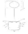
- Figure 1 is a schematic front view of a first exemplary embodiment of the invention, shown applied to a feed assembly.
- Figure 2 is a schematic isometric close-up view of Figure 1, with the receptacle and a portion of the feed assembly cover omitted for clarity.
- Figure 3 is a schematic close-up view of Figure 1, normal to a cross section of the receptacle, demonstrating a left range of adjustment.
- Figure 4 is a schematic close-up view of Figure 1, normal to a cross section of the receptacle, demonstrating a right range of adjustment.
- Figure 5 is a schematic isometric close-up view of a second exemplary embodiment of the invention, with the receptacle and a portion of the feed assembly cover omitted for clarity.
- Figure 6 is a schematic close-up view of the alternative embodiment, normal to a cross section of the receptacle, demonstrating a left range of adjustment.
- Figure 7 is a schematic close-up view of the alternative embodiment, normal to a cross section of the receptacle, demonstrating a right range of adjustment.
- Figure 8 is a schematic isometric view of a first adjustment scale embodiment, fine adjusting hardware omitted for clarity.
- Figure 9 is a schematic isometric view of a second adjustment scale embodiment fine adjusting hardware omitted for clarity.
- Figure 10 is a schematic isometric view of a third adjustment scale embodiment fine adjusting hardware omitted for clarity.
- Applicant has recognized that rather than adjusting the entire antenna structure, accurate azimuth fine tuning functionality may be cost effectively implemented by adjusting the feed assembly with respect to the feed assembly connection with the boom arm and or the reflector of the antenna.
- a small adjustment to the orientation of the feed assembly with respect to the reflector adjusts the, for example, azimuth beam alignment but does not significantly affect alignment of the feed assembly with a focal area of the reflector.
- a first exemplary embodiment of the invention is shown in figures 1-4.
- a feed assembly 2 is coupled to a receptacle 4 such as an adjusting collar 6 that is in turn mounted to a boom arm of the reflector antenna (not shown).
- a receptacle 4 such as an adjusting collar 6 that is in turn mounted to a boom arm of the reflector antenna (not shown).
- Existing feed assembly 2 configurations may have a mounting lip 8 adapted to fit into the open end of a hollow boom arm. These configurations may be readily adapted according to the invention with a minimum of additional adaptations.
- the mounting lip 8 is inserted into an adjusting slot 10 of the receptacle 4, here demonstrated as an adjusting collar 6.
- the receptacle 4 function may be incorporated into an end of the boom arm and or directly to the main reflector.
- the adjusting slot 10 is dimensioned with respect to the mounting lip 8 for a close vertical fit and free horizontal movement over a desired range as demonstrated by figures 2 and 3. If output(s) 12 of the feed assembly 2 are being routed through a hollow boom arm, the adjusting slot 10 may be formed passing end to end through the receptacle 4, providing an internal cable path.
- An adjusting knob 14 with a threaded shaft 16 threads into a corresponding threaded hole 18 formed in a first side 20 of the receptacle 4.
- the threaded shaft 16 extends into the adjusting slot 10 into contact with a first side 20 of the mounting lip 8, setting the horizontal position of the mounting lip 8 and thereby the feed assembly 2 within the adjusting slot 10.
- a seating hole 22 may be formed in the mounting lip 8 to receive the distal end of the threaded shaft 16.
- a guide pin 24 positioned in a second side 26 of the adjusting slot 10 also fits into a corresponding seating hole 28 on the second side 26 of the mounting lip.
- a bias spring 30 on the guide pin 24 is compressed between the receptacle 4 and the mounting lip 8, biasing the receptacle 4 against the threaded shaft 16.
- the mounting lip 8 is moved against the bias spring 30.
- the bias spring 30 holds the mounting lip 8 against the retracting distal end of the threaded shaft 16. Thereby, the mounting lip 8 may be positioned horizontally within the receptacle 4 according to the position of the threaded shaft16.
- a further benefit of the bias spring 30 is that the constant bias against the threaded shaft 16 reduces the potential for any threading slop or backlash that may be present between the threading of the threaded shaft 16 and the threaded hole 18.
- Angular resolution of azimuth corrections introduced by horizontal feed assembly 2 movements resulting from rotation of the adjusting knob 14 is a function of the selected thread pitch applied to the threaded shaft 16 and corresponding threaded hole 18.
- a thread pitch resulting in a threaded shaft 16 displacement of 2.5 mm every 4 turns equates to an angular resolution of approximately 0.025 degrees for every quarter turn of the adjusting knob 14.
- the means for positioning the mounting lip within the adjusting slot may be adapted according to a range of different threaded shaft configurations, as shown for example by figures 5-7 the length of the threaded shaft 16 may be extended to pass across the receptacle 4, through the mounting lip 8. The receptacle 4 then acts as a carrier for the threaded shaft 16 now threaded through the mounting lip 8 of the feed assembly 2.
- a bias spring 30 for example in the form of a coil spring as shown in figures 2 and 3 or a spring washer, not shown, may be added at either inside or outside end of the receptacle 4 or adjusting slot 10 to reduce the potential for any threading slop or backlash that may be present between the threaded shaft 16 and the threads within the mounting lip 8.
- vernier scale(s) 34 of various types may be applied to the receptacle 4 to provide a ready visual reference of azimuth adjustment progress as the adjustment knob 14 is turned. At least one aperture in the form of a slot 36 or series of scale hole(s) 38 in the receptacle 4 may be used to view scale marking(s) 40 printed upon, etched or cast into the mounting lip 8. Alternatively, the vernier scale(s) 34 may be applied along a top edge of the receptacle 4, proximate corresponding scale marking(s) 40 on the feed assembly 2 above the mounting lip 8, reducing the number of required receptacle 4 machining steps.
- retaining fasteners may be applied passing through horizontally elongated fastener slot(s) 42 formed in the top of the receptacle 4 either bolting across or threading into the mounting lip 8 of the feed assembly 2.
Landscapes
- Physics & Mathematics (AREA)
- Engineering & Computer Science (AREA)
- Astronomy & Astrophysics (AREA)
- General Physics & Mathematics (AREA)
- Remote Sensing (AREA)
- Aviation & Aerospace Engineering (AREA)
- Aerials With Secondary Devices (AREA)
- Variable-Direction Aerials And Aerial Arrays (AREA)
- Support Of Aerials (AREA)
Abstract
Description
- For optimal performance, a directional antenna such as a reflector antenna must be closely aligned with a target signal source. Alignment of a reflector antenna is typically performed via an adjustable antenna mount that, with respect to a fixed mounting point, is adjustable in azimuth and elevation to orient the antenna towards the target.
- Because the entire antenna assembly is adjusted, the adjustable antenna mount must be designed to support the entire antenna mass and also withstand any expected environmental factors such as wind shear and or ice loading. Adjustable antenna mounts that are both strong and easily adjustable with precision significantly increase the cost of the resulting antenna.
- High resolution azimuth adjustment capability is increasingly important for multiple feed reflector antennas used with satellites positioned in equatorial orbit. Where multiple feeds are applied to a single reflector to simultaneously receive closely spaced beams from different satellites, alignment is critical to achieve acceptable signal performance with respect to each of the satellites. Although equatorial orbits are generally constant by definition, in reality there is a certain range of azimuth "wobble" to an equatorial orbit that determines the precise position of the satellite at any given instant. When multiple satellites are targeted using multiple feeds of a common reflector the "wobble" position of each satellite may at one extreme or the other unacceptably degrade performance of the other signals as they move through their own ranges of positional "wobble". High resolution adjustment capability may also be used for a single feed reflector and or terrestrial applications where precision accuracy is required.
- To avoid configuring a reflector antenna for a primary satellite alignment other than the middle of a known wobble range an installation technician first aligns the antenna for maximum signal strength with respect to the primary satellite. Then, by contacting a satellite ground control resource the installation technician can obtain a desired azimuth offset representing the present distance of the primary satellite from the center of its wobble range. These adjustments are extremely small, creating a need for azimuth adjustments that are easy to perform, accurately controlled, easily measurable and reliably repeatable for a given input.
- The increasing competition for reflector antennas adapted for high volume consumer applications such as satellite tv and or internet communications has focused attention on cost reductions resulting from increased materials, manufacturing and service efficiencies. Further, reductions in required assembly operations and the total number of discrete parts are desired.
- Therefore, it is an object of the invention to provide an apparatus that overcomes deficiencies in the prior art.
- The accompanying drawings, which are incorporated in and constitute a part of this specification, illustrate embodiments of the invention and, together with the general and detailed descriptions of the invention appearing herein, serve to explain the principles of the invention.
- Figure 1 is a schematic front view of a first exemplary embodiment of the invention, shown applied to a feed assembly.
- Figure 2 is a schematic isometric close-up view of Figure 1, with the receptacle and a portion of the feed assembly cover omitted for clarity.
- Figure 3 is a schematic close-up view of Figure 1, normal to a cross section of the receptacle, demonstrating a left range of adjustment.
- Figure 4 is a schematic close-up view of Figure 1, normal to a cross section of the receptacle, demonstrating a right range of adjustment.
- Figure 5 is a schematic isometric close-up view of a second exemplary embodiment of the invention, with the receptacle and a portion of the feed assembly cover omitted for clarity.
- Figure 6 is a schematic close-up view of the alternative embodiment, normal to a cross section of the receptacle, demonstrating a left range of adjustment.
- Figure 7 is a schematic close-up view of the alternative embodiment, normal to a cross section of the receptacle, demonstrating a right range of adjustment.
- Figure 8 is a schematic isometric view of a first adjustment scale embodiment, fine adjusting hardware omitted for clarity.
- Figure 9 is a schematic isometric view of a second adjustment scale embodiment fine adjusting hardware omitted for clarity.
- Figure 10 is a schematic isometric view of a third adjustment scale embodiment fine adjusting hardware omitted for clarity.
- DETAILED DESCRIPTION
- Applicant has recognized that rather than adjusting the entire antenna structure, accurate azimuth fine tuning functionality may be cost effectively implemented by adjusting the feed assembly with respect to the feed assembly connection with the boom arm and or the reflector of the antenna. A small adjustment to the orientation of the feed assembly with respect to the reflector adjusts the, for example, azimuth beam alignment but does not significantly affect alignment of the feed assembly with a focal area of the reflector.
- A first exemplary embodiment of the invention is shown in figures 1-4. A
feed assembly 2 is coupled to areceptacle 4 such as an adjustingcollar 6 that is in turn mounted to a boom arm of the reflector antenna (not shown). Existingfeed assembly 2 configurations may have amounting lip 8 adapted to fit into the open end of a hollow boom arm. These configurations may be readily adapted according to the invention with a minimum of additional adaptations. Themounting lip 8 is inserted into an adjustingslot 10 of thereceptacle 4, here demonstrated as an adjustingcollar 6.
Alternatively, thereceptacle 4 function may be incorporated into an end of the boom arm and or directly to the main reflector. - The adjusting
slot 10 is dimensioned with respect to themounting lip 8 for a close vertical fit and free horizontal movement over a desired range as demonstrated by figures 2 and 3. If output(s) 12 of thefeed assembly 2 are being routed through a hollow boom arm, the adjustingslot 10 may be formed passing end to end through thereceptacle 4, providing an internal cable path. - An adjusting
knob 14 with a threadedshaft 16 threads into a corresponding threadedhole 18 formed in afirst side 20 of thereceptacle 4. The threadedshaft 16 extends into the adjustingslot 10 into contact with afirst side 20 of themounting lip 8, setting the horizontal position of themounting lip 8 and thereby the feedassembly 2 within theadjusting slot 10. To minimize the opportunity for the threadedshaft 16 to skew as it rotates against themounting lip 8, aseating hole 22 may be formed in themounting lip 8 to receive the distal end of the threadedshaft 16. Aguide pin 24 positioned in asecond side 26 of the adjustingslot 10 also fits into a corresponding seating hole 28 on thesecond side 26 of the mounting lip. Abias spring 30 on theguide pin 24 is compressed between thereceptacle 4 and themounting lip 8, biasing thereceptacle 4 against the threadedshaft 16. - As the adjusting
knob 14 is turned to thread the threadedshaft 16 into the threadedhole 18 of thereceptacle 4, themounting lip 8 is moved against thebias spring 30. Conversely, as the adjustingknob 14 is turned to thread the threadedshaft 16 out of thereceptacle 4, thebias spring 30 holds themounting lip 8 against the retracting distal end of the threadedshaft 16. Thereby, themounting lip 8 may be positioned horizontally within thereceptacle 4 according to the position of the threaded shaft16. A further benefit of thebias spring 30 is that the constant bias against the threadedshaft 16 reduces the potential for any threading slop or backlash that may be present between the threading of the threadedshaft 16 and the threadedhole 18. - Angular resolution of azimuth corrections introduced by
horizontal feed assembly 2 movements resulting from rotation of the adjustingknob 14 is a function of the selected thread pitch applied to the threadedshaft 16 and corresponding threadedhole 18. For example, in a typical consumer digital satellite TV reflector antenna embodiment, a thread pitch resulting in a threadedshaft 16 displacement of 2.5 mm every 4 turns equates to an angular resolution of approximately 0.025 degrees for every quarter turn of the adjustingknob 14. - In alternative embodiments the means for positioning the mounting lip within the adjusting slot may be adapted according to a range of different threaded shaft configurations, as shown for example by figures 5-7 the length of the threaded
shaft 16 may be extended to pass across thereceptacle 4, through themounting lip 8. Thereceptacle 4 then acts as a carrier for the threadedshaft 16 now threaded through themounting lip 8 of thefeed assembly 2. With either end of the threadedshaft 16 passing through unthreaded hole(s) at both sides of thereceptacle 4 and held longitudinally captive between the adjustingknob 14 and astop 33 such as a retaining clip or the like on the distal end of the threadedshaft 16, respectively, rotation of the threadedshaft 16 via the adjustingknob 14 operates to thread themounting lip 8 and thereby thefeed assembly 2 left or right within the adjustingslot 10, as shown in figures 6 and 7. If desired, abias spring 30 for example in the form of a coil spring as shown in figures 2 and 3 or a spring washer, not shown, may be added at either inside or outside end of thereceptacle 4 or adjustingslot 10 to reduce the potential for any threading slop or backlash that may be present between the threadedshaft 16 and the threads within themounting lip 8. - As shown in figures 8-10, vernier scale(s) 34 of various types may be applied to the
receptacle 4 to provide a ready visual reference of azimuth adjustment progress as theadjustment knob 14 is turned. At least one aperture in the form of aslot 36 or series of scale hole(s) 38 in thereceptacle 4 may be used to view scale marking(s) 40 printed upon, etched or cast into themounting lip 8. Alternatively, the vernier scale(s) 34 may be applied along a top edge of thereceptacle 4, proximate corresponding scale marking(s) 40 on thefeed assembly 2 above themounting lip 8, reducing the number of requiredreceptacle 4 machining steps. - Although the adjusting
knob 14 precisely positions thefeed assembly 2 within thereceptacle 4, further fastening may be applied to securely hold thefeed assembly 2 in the final adjustment position. In the present embodiment(s), retaining fasteners (not shown) may be applied passing through horizontally elongated fastener slot(s) 42 formed in the top of thereceptacle 4 either bolting across or threading into themounting lip 8 of thefeed assembly 2. When a final adjustment of thefeed assembly 2 with respect to thereceptacle 4 has been completed, thefeed assembly 2 may be securely fixed in place by tightening the retaining fastener(s). - One skilled in the art will appreciate that the precision orientation adjustments enabled by the present invention significantly reduces the complexity and precision adjustability requirements of the general antenna mount required for a reflector antenna incorporating the invention, resulting in a significant reduction in overall cost. Also, the time required for installation and configuration of the reflector antenna is similarly reduced.
- It should further be appreciated that, while the embodiments described herein demonstrate a feed assembly arrangement oriented to provide for feed assembly fine azimuth adjustment, the invention may also be applied within the scope of the attached claims with respect to elevation adjustment or a combination thereof via an adaptation of the adjusting slot orientation.
-
Table of Parts 2 feed assembly 4 receptacle 6 adjusting collar 8 mounting lip 10 adjusting slot 12 output 14 adjusting knob 16 threaded shaft 18 threaded hole 20 first side 22 seating hole 24 guide pin 26 second side 28 seating hole 30 bias spring 32 threaded rod 33 stop 34 vernier scale 36 slot 38 scale hole 40 scale marking 42 fastener slot - Where in the foregoing description reference has been made to ratios, integers, components or modules having known equivalents then such equivalents are herein incorporated as if individually set forth.
- While the present invention has been illustrated by the description of the embodiments thereof, and while the embodiments have been described in considerable detail, it is not the intention of the applicant to restrict or in any way limit the scope of the appended claims to such detail. Additional advantages and modifications will readily appear to those skilled in the art. Therefore, the invention in its broader aspects is not limited to the specific details, representative apparatus, methods, and illustrative examples shown and described. Accordingly, departures may be made from such details without departure from the spirit or scope of applicant's general inventive concept. Further, it is to be appreciated that improvements and/or modifications may be made thereto without departing from the scope or spirit of the present invention as defined by the following claims.
Claims (20)
the bias spring mounted on the guide pin.
Applications Claiming Priority (1)
| Application Number | Priority Date | Filing Date | Title |
|---|---|---|---|
| US10/907,205 US7196675B2 (en) | 2005-03-24 | 2005-03-24 | High resolution orientation adjusting arrangement for feed assembly |
Publications (2)
| Publication Number | Publication Date |
|---|---|
| EP1705746A1 true EP1705746A1 (en) | 2006-09-27 |
| EP1705746B1 EP1705746B1 (en) | 2009-09-30 |
Family
ID=36250762
Family Applications (1)
| Application Number | Title | Priority Date | Filing Date |
|---|---|---|---|
| EP06110199A Expired - Lifetime EP1705746B1 (en) | 2005-03-24 | 2006-02-21 | High resolution orientation adjusting arrangement for feed assembly |
Country Status (4)
| Country | Link |
|---|---|
| US (1) | US7196675B2 (en) |
| EP (1) | EP1705746B1 (en) |
| AT (1) | ATE444574T1 (en) |
| DE (1) | DE602006009430D1 (en) |
Citations (5)
| Publication number | Priority date | Publication date | Assignee | Title |
|---|---|---|---|---|
| EP0253425A2 (en) * | 1986-07-18 | 1988-01-20 | Siemens Telecomunicazioni S.P.A. | Angular-diversity radiating system for tropospheric-scatter radio links |
| WO1999060658A1 (en) * | 1998-05-15 | 1999-11-25 | Cambridge Industries Limited | Low noise block (lnb) mounting system |
| EP1017125A2 (en) * | 1998-12-28 | 2000-07-05 | Microelectronics Technology | Satellite block-down receiver set having adjustable mounting |
| WO2002035649A1 (en) * | 2000-10-28 | 2002-05-02 | Kwon Tae In | Lnb holder for satellite antenna |
| EP1227541A2 (en) * | 2001-01-30 | 2002-07-31 | Andrew AG | Reflector antenna |
Family Cites Families (30)
| Publication number | Priority date | Publication date | Assignee | Title |
|---|---|---|---|---|
| US4251819A (en) * | 1978-07-24 | 1981-02-17 | Ford Aerospace & Communications Corp. | Variable support apparatus |
| US4404565A (en) * | 1981-11-18 | 1983-09-13 | Radiation Systems Incorporated | Quickly erectable antenna support structure |
| US4652890A (en) * | 1984-07-24 | 1987-03-24 | Crean Robert F | High rigidity, low center of gravity polar mount for dish type antenna |
| US4692771A (en) * | 1985-03-28 | 1987-09-08 | Satellite Technology Services, Inc. | Antenna dish reflector with integral azimuth track |
| US4819006A (en) * | 1986-05-08 | 1989-04-04 | Aluminum Company Of America | Mount for supporting a parabolic antenna |
| SE458065B (en) * | 1986-10-16 | 1989-02-20 | Tore Eklund | PARABOLAN TEST PARTS WHICH ARE MOVABLE FOR ADJUSTMENT AS WELL AS EXTENDING IN THE PLANET WHICH MAKES AN ANGLE ADJUSTMENT IN THE PLANET |
| US4819007A (en) * | 1987-06-22 | 1989-04-04 | Andrew Corporation | Supporting structure for reflector-type microwave antennas |
| DE68920184T2 (en) * | 1988-04-08 | 1995-06-22 | Toshiba Kawasaki Kk | Portable antenna device. |
| FR2640086B1 (en) * | 1988-10-21 | 1991-01-18 | Alcatel Transmission | AZIMUT-ELEVATION TYPE ANTENNA SUPPORT |
| US4924239A (en) * | 1989-02-28 | 1990-05-08 | The United States Of America As Represented By The Secretary Of The Air Force | Antenna mounting apparatus |
| US5657031A (en) * | 1991-01-07 | 1997-08-12 | Anderson; Fredrick C. | Earth station antenna system |
| WO1996013075A1 (en) * | 1994-10-24 | 1996-05-02 | Maxview Limited | Improvements in or relating to antenna mounts |
| US5402140A (en) * | 1993-08-20 | 1995-03-28 | Winegard Company | Horizon-to-horizon TVRO antenna mount |
| US5870060A (en) * | 1996-05-01 | 1999-02-09 | Trw Inc. | Feeder link antenna |
| US5999139A (en) * | 1997-08-27 | 1999-12-07 | Marconi Aerospace Systems Inc. | Two-axis satellite antenna mounting and tracking assembly |
| US5982333A (en) * | 1997-09-03 | 1999-11-09 | Qualcomm Incorporated | Steerable antenna system |
| US5933123A (en) * | 1997-12-03 | 1999-08-03 | Kaul-Tronics, Inc. | Combined satellite and terrestrial antenna |
| US6225962B1 (en) * | 1998-09-18 | 2001-05-01 | Gabriel Electronics Incorporated | Apparatus and method for an adjustable linkage |
| US6342870B1 (en) * | 1999-03-12 | 2002-01-29 | Harris Corporation | Antenna frame structure mounting and alignment |
| US6208317B1 (en) * | 2000-02-15 | 2001-03-27 | Hughes Electronics Corporation | Hub mounted bending beam for shape adjustment of springback reflectors |
| TW465812U (en) * | 2000-05-29 | 2001-11-21 | Acer Neweb Corp | Rotation device of disc-shape antenna |
| US6388614B2 (en) * | 2000-07-06 | 2002-05-14 | Hughes Electronics Corporation | Antenna aperture cover for antenna pointing an improved antenna pointing method using aperture cover |
| US6683581B2 (en) * | 2000-12-29 | 2004-01-27 | Bellsouth Intellectual Property Corporation | Antenna alignment devices |
| US6507325B2 (en) * | 2000-12-29 | 2003-01-14 | Bellsouth Intellectual Property Corporation | Antenna alignment configuration |
| US6404400B1 (en) * | 2001-01-30 | 2002-06-11 | Andrew Corporation | Antenna mount assembly |
| US6512485B2 (en) * | 2001-03-12 | 2003-01-28 | Wildblue Communications, Inc. | Multi-band antenna for bundled broadband satellite internet access and DBS television service |
| US6630912B2 (en) * | 2001-03-20 | 2003-10-07 | Netune Communications, Inc. | Mount and controller assembly |
| US6462718B1 (en) * | 2001-03-20 | 2002-10-08 | Netune Communications, Inc. | Steerable antenna assembly |
| US6657598B2 (en) * | 2001-10-12 | 2003-12-02 | Andrew Corporation | Method of and apparatus for antenna alignment |
| US20040169114A1 (en) * | 2002-11-27 | 2004-09-02 | Barry Dierkes | Satellite dish antenna mount |
-
2005
- 2005-03-24 US US10/907,205 patent/US7196675B2/en not_active Expired - Fee Related
-
2006
- 2006-02-21 AT AT06110199T patent/ATE444574T1/en not_active IP Right Cessation
- 2006-02-21 EP EP06110199A patent/EP1705746B1/en not_active Expired - Lifetime
- 2006-02-21 DE DE602006009430T patent/DE602006009430D1/en not_active Expired - Lifetime
Patent Citations (5)
| Publication number | Priority date | Publication date | Assignee | Title |
|---|---|---|---|---|
| EP0253425A2 (en) * | 1986-07-18 | 1988-01-20 | Siemens Telecomunicazioni S.P.A. | Angular-diversity radiating system for tropospheric-scatter radio links |
| WO1999060658A1 (en) * | 1998-05-15 | 1999-11-25 | Cambridge Industries Limited | Low noise block (lnb) mounting system |
| EP1017125A2 (en) * | 1998-12-28 | 2000-07-05 | Microelectronics Technology | Satellite block-down receiver set having adjustable mounting |
| WO2002035649A1 (en) * | 2000-10-28 | 2002-05-02 | Kwon Tae In | Lnb holder for satellite antenna |
| EP1227541A2 (en) * | 2001-01-30 | 2002-07-31 | Andrew AG | Reflector antenna |
Also Published As
| Publication number | Publication date |
|---|---|
| EP1705746B1 (en) | 2009-09-30 |
| ATE444574T1 (en) | 2009-10-15 |
| US7196675B2 (en) | 2007-03-27 |
| US20060214868A1 (en) | 2006-09-28 |
| DE602006009430D1 (en) | 2009-11-12 |
Similar Documents
| Publication | Publication Date | Title |
|---|---|---|
| US10276914B2 (en) | Transversely clampable linear adjustment mechanism | |
| US7142168B1 (en) | Apparatus for mounting and adjusting a satellite antenna | |
| EP1705745B1 (en) | Antenna mount with fine adjustment cam | |
| US9136582B2 (en) | Compact antenna mount | |
| US9972906B2 (en) | Two-way antenna mounting bracket and assembly with independently adjustable electromechanical antenna tilt and azimuthal steering for beam reshaping | |
| EP2817851B1 (en) | Alignment stable adjustable antenna mount | |
| US7046210B1 (en) | Precision adjustment antenna mount and alignment method | |
| EP2322944B1 (en) | High frequency measurement assembly and method for measuring a high frequency test subject, in particular an antenna | |
| US8456376B2 (en) | Position adjustment device and satellite antenna thereof | |
| US20100259462A1 (en) | Angle adjustment apparatus of dish antenna and dish antenna using the same | |
| CN102110868A (en) | Method and apparatus for fine polarization reflector antenna adjustment | |
| US11631929B2 (en) | Fastening device and associated method | |
| EP1936735A1 (en) | Low AzEL lockdown shift antenna mount | |
| US11387553B2 (en) | Mechanical transmission mechanism and base station antenna | |
| US8350778B2 (en) | Adjustment method for dish antenna | |
| EP1705746B1 (en) | High resolution orientation adjusting arrangement for feed assembly | |
| DE102010035508B4 (en) | Device for tracking a subreflector and method of use | |
| DE20314930U1 (en) | Satellite antenna with photovoltaic elements for power supply | |
| DE102008059268A1 (en) | Positional recognition device for antenna, particularly mobile phone antenna, has integrated inclination sensor and global positioning system, where device is provided in control unit for adjusting electrical beam deflection with antenna | |
| US7173575B2 (en) | Reflector antenna support structure | |
| EP2118963A1 (en) | Array for influencing the radiation characteristics of a reflector antenna, particularly a centrally focused reflector antenna | |
| CN107895837A (en) | A kind of high-precision antenna | |
| US20230361465A1 (en) | Transmission device for base station antenna and base station antenna | |
| JPH036006Y2 (en) | ||
| JPH036007Y2 (en) |
Legal Events
| Date | Code | Title | Description |
|---|---|---|---|
| PUAI | Public reference made under article 153(3) epc to a published international application that has entered the european phase |
Free format text: ORIGINAL CODE: 0009012 |
|
| AK | Designated contracting states |
Kind code of ref document: A1 Designated state(s): AT BE BG CH CY CZ DE DK EE ES FI FR GB GR HU IE IS IT LI LT LU LV MC NL PL PT RO SE SI SK TR |
|
| AX | Request for extension of the european patent |
Extension state: AL BA HR MK YU |
|
| 17P | Request for examination filed |
Effective date: 20070305 |
|
| 17Q | First examination report despatched |
Effective date: 20070416 |
|
| AKX | Designation fees paid |
Designated state(s): AT BE BG CH CY CZ DE DK EE ES FI FR GB GR HU IE IS IT LI LT LU LV MC NL PL PT RO SE SI SK TR |
|
| GRAP | Despatch of communication of intention to grant a patent |
Free format text: ORIGINAL CODE: EPIDOSNIGR1 |
|
| GRAS | Grant fee paid |
Free format text: ORIGINAL CODE: EPIDOSNIGR3 |
|
| GRAA | (expected) grant |
Free format text: ORIGINAL CODE: 0009210 |
|
| AK | Designated contracting states |
Kind code of ref document: B1 Designated state(s): AT BE BG CH CY CZ DE DK EE ES FI FR GB GR HU IE IS IT LI LT LU LV MC NL PL PT RO SE SI SK TR |
|
| REG | Reference to a national code |
Ref country code: GB Ref legal event code: FG4D Ref country code: CH Ref legal event code: EP |
|
| REG | Reference to a national code |
Ref country code: IE Ref legal event code: FG4D |
|
| REF | Corresponds to: |
Ref document number: 602006009430 Country of ref document: DE Date of ref document: 20091112 Kind code of ref document: P |
|
| RAP2 | Party data changed (patent owner data changed or rights of a patent transferred) |
Owner name: ASC SIGNAL INTERNATIONAL CORPORATION |
|
| RAP2 | Party data changed (patent owner data changed or rights of a patent transferred) |
Owner name: RAVEN MANUFACTURING LIMITED |
|
| PG25 | Lapsed in a contracting state [announced via postgrant information from national office to epo] |
Ref country code: LT Free format text: LAPSE BECAUSE OF FAILURE TO SUBMIT A TRANSLATION OF THE DESCRIPTION OR TO PAY THE FEE WITHIN THE PRESCRIBED TIME-LIMIT Effective date: 20090930 Ref country code: FI Free format text: LAPSE BECAUSE OF FAILURE TO SUBMIT A TRANSLATION OF THE DESCRIPTION OR TO PAY THE FEE WITHIN THE PRESCRIBED TIME-LIMIT Effective date: 20090930 Ref country code: SE Free format text: LAPSE BECAUSE OF FAILURE TO SUBMIT A TRANSLATION OF THE DESCRIPTION OR TO PAY THE FEE WITHIN THE PRESCRIBED TIME-LIMIT Effective date: 20090930 |
|
| REG | Reference to a national code |
Ref country code: GB Ref legal event code: 732E Free format text: REGISTERED BETWEEN 20100128 AND 20100203 |
|
| LTIE | Lt: invalidation of european patent or patent extension |
Effective date: 20090930 |
|
| PG25 | Lapsed in a contracting state [announced via postgrant information from national office to epo] |
Ref country code: PL Free format text: LAPSE BECAUSE OF FAILURE TO SUBMIT A TRANSLATION OF THE DESCRIPTION OR TO PAY THE FEE WITHIN THE PRESCRIBED TIME-LIMIT Effective date: 20090930 Ref country code: LV Free format text: LAPSE BECAUSE OF FAILURE TO SUBMIT A TRANSLATION OF THE DESCRIPTION OR TO PAY THE FEE WITHIN THE PRESCRIBED TIME-LIMIT Effective date: 20090930 Ref country code: SI Free format text: LAPSE BECAUSE OF FAILURE TO SUBMIT A TRANSLATION OF THE DESCRIPTION OR TO PAY THE FEE WITHIN THE PRESCRIBED TIME-LIMIT Effective date: 20090930 |
|
| NLT2 | Nl: modifications (of names), taken from the european patent patent bulletin |
Owner name: ASC SIGNAL INTERNATIONAL CORPORATION Effective date: 20100113 |
|
| NLV1 | Nl: lapsed or annulled due to failure to fulfill the requirements of art. 29p and 29m of the patents act | ||
| PG25 | Lapsed in a contracting state [announced via postgrant information from national office to epo] |
Ref country code: IS Free format text: LAPSE BECAUSE OF FAILURE TO SUBMIT A TRANSLATION OF THE DESCRIPTION OR TO PAY THE FEE WITHIN THE PRESCRIBED TIME-LIMIT Effective date: 20100130 Ref country code: PT Free format text: LAPSE BECAUSE OF FAILURE TO SUBMIT A TRANSLATION OF THE DESCRIPTION OR TO PAY THE FEE WITHIN THE PRESCRIBED TIME-LIMIT Effective date: 20100201 Ref country code: CZ Free format text: LAPSE BECAUSE OF FAILURE TO SUBMIT A TRANSLATION OF THE DESCRIPTION OR TO PAY THE FEE WITHIN THE PRESCRIBED TIME-LIMIT Effective date: 20090930 Ref country code: ES Free format text: LAPSE BECAUSE OF FAILURE TO SUBMIT A TRANSLATION OF THE DESCRIPTION OR TO PAY THE FEE WITHIN THE PRESCRIBED TIME-LIMIT Effective date: 20100110 Ref country code: RO Free format text: LAPSE BECAUSE OF FAILURE TO SUBMIT A TRANSLATION OF THE DESCRIPTION OR TO PAY THE FEE WITHIN THE PRESCRIBED TIME-LIMIT Effective date: 20090930 Ref country code: EE Free format text: LAPSE BECAUSE OF FAILURE TO SUBMIT A TRANSLATION OF THE DESCRIPTION OR TO PAY THE FEE WITHIN THE PRESCRIBED TIME-LIMIT Effective date: 20090930 |
|
| PG25 | Lapsed in a contracting state [announced via postgrant information from national office to epo] |
Ref country code: SK Free format text: LAPSE BECAUSE OF FAILURE TO SUBMIT A TRANSLATION OF THE DESCRIPTION OR TO PAY THE FEE WITHIN THE PRESCRIBED TIME-LIMIT Effective date: 20090930 Ref country code: CY Free format text: LAPSE BECAUSE OF FAILURE TO SUBMIT A TRANSLATION OF THE DESCRIPTION OR TO PAY THE FEE WITHIN THE PRESCRIBED TIME-LIMIT Effective date: 20090930 |
|
| PG25 | Lapsed in a contracting state [announced via postgrant information from national office to epo] |
Ref country code: AT Free format text: LAPSE BECAUSE OF FAILURE TO SUBMIT A TRANSLATION OF THE DESCRIPTION OR TO PAY THE FEE WITHIN THE PRESCRIBED TIME-LIMIT Effective date: 20090930 Ref country code: BE Free format text: LAPSE BECAUSE OF FAILURE TO SUBMIT A TRANSLATION OF THE DESCRIPTION OR TO PAY THE FEE WITHIN THE PRESCRIBED TIME-LIMIT Effective date: 20090930 |
|
| PG25 | Lapsed in a contracting state [announced via postgrant information from national office to epo] |
Ref country code: NL Free format text: LAPSE BECAUSE OF FAILURE TO SUBMIT A TRANSLATION OF THE DESCRIPTION OR TO PAY THE FEE WITHIN THE PRESCRIBED TIME-LIMIT Effective date: 20090930 Ref country code: DK Free format text: LAPSE BECAUSE OF FAILURE TO SUBMIT A TRANSLATION OF THE DESCRIPTION OR TO PAY THE FEE WITHIN THE PRESCRIBED TIME-LIMIT Effective date: 20090930 |
|
| PLBE | No opposition filed within time limit |
Free format text: ORIGINAL CODE: 0009261 |
|
| STAA | Information on the status of an ep patent application or granted ep patent |
Free format text: STATUS: NO OPPOSITION FILED WITHIN TIME LIMIT |
|
| 26N | No opposition filed |
Effective date: 20100701 |
|
| REG | Reference to a national code |
Ref country code: CH Ref legal event code: PL |
|
| PG25 | Lapsed in a contracting state [announced via postgrant information from national office to epo] |
Ref country code: CH Free format text: LAPSE BECAUSE OF NON-PAYMENT OF DUE FEES Effective date: 20100228 Ref country code: GR Free format text: LAPSE BECAUSE OF FAILURE TO SUBMIT A TRANSLATION OF THE DESCRIPTION OR TO PAY THE FEE WITHIN THE PRESCRIBED TIME-LIMIT Effective date: 20091231 Ref country code: LI Free format text: LAPSE BECAUSE OF NON-PAYMENT OF DUE FEES Effective date: 20100228 Ref country code: MC Free format text: LAPSE BECAUSE OF NON-PAYMENT OF DUE FEES Effective date: 20100301 |
|
| PG25 | Lapsed in a contracting state [announced via postgrant information from national office to epo] |
Ref country code: IE Free format text: LAPSE BECAUSE OF NON-PAYMENT OF DUE FEES Effective date: 20100221 |
|
| PG25 | Lapsed in a contracting state [announced via postgrant information from national office to epo] |
Ref country code: IT Free format text: LAPSE BECAUSE OF FAILURE TO SUBMIT A TRANSLATION OF THE DESCRIPTION OR TO PAY THE FEE WITHIN THE PRESCRIBED TIME-LIMIT Effective date: 20090930 |
|
| PG25 | Lapsed in a contracting state [announced via postgrant information from national office to epo] |
Ref country code: BG Free format text: LAPSE BECAUSE OF FAILURE TO SUBMIT A TRANSLATION OF THE DESCRIPTION OR TO PAY THE FEE WITHIN THE PRESCRIBED TIME-LIMIT Effective date: 20090930 Ref country code: LU Free format text: LAPSE BECAUSE OF NON-PAYMENT OF DUE FEES Effective date: 20100221 Ref country code: HU Free format text: LAPSE BECAUSE OF FAILURE TO SUBMIT A TRANSLATION OF THE DESCRIPTION OR TO PAY THE FEE WITHIN THE PRESCRIBED TIME-LIMIT Effective date: 20100401 |
|
| PG25 | Lapsed in a contracting state [announced via postgrant information from national office to epo] |
Ref country code: TR Free format text: LAPSE BECAUSE OF FAILURE TO SUBMIT A TRANSLATION OF THE DESCRIPTION OR TO PAY THE FEE WITHIN THE PRESCRIBED TIME-LIMIT Effective date: 20090930 |
|
| PGFP | Annual fee paid to national office [announced via postgrant information from national office to epo] |
Ref country code: GB Payment date: 20130115 Year of fee payment: 8 |
|
| REG | Reference to a national code |
Ref country code: DE Ref legal event code: R082 Ref document number: 602006009430 Country of ref document: DE Representative=s name: MOSER & GOETZE PATENTANWAELTE, DE |
|
| REG | Reference to a national code |
Ref country code: GB Ref legal event code: 732E Free format text: REGISTERED BETWEEN 20140508 AND 20140514 |
|
| REG | Reference to a national code |
Ref country code: DE Ref legal event code: R082 Ref document number: 602006009430 Country of ref document: DE Representative=s name: MOSER & GOETZE PATENTANWAELTE, DE Effective date: 20140514 Ref country code: DE Ref legal event code: R081 Ref document number: 602006009430 Country of ref document: DE Owner name: RAVEN GROUP LTD., GB Free format text: FORMER OWNER: RAVEN MANUFACTURING LTD., ACCRINGTON, GB Effective date: 20140514 Ref country code: DE Ref legal event code: R081 Ref document number: 602006009430 Country of ref document: DE Owner name: RAVEN GROUP LTD., GB Free format text: FORMER OWNER: RAVEN MANUFACTURING LTD., ACCRINGTON, LANCASHIRE, GB Effective date: 20140514 Ref country code: DE Ref legal event code: R082 Ref document number: 602006009430 Country of ref document: DE Representative=s name: MOSER GOETZE & PARTNER PATENTANWAELTE MBB, DE Effective date: 20140514 |
|
| REG | Reference to a national code |
Ref country code: FR Ref legal event code: TP Owner name: RAVEN GROUP LIMITED, GB Effective date: 20140526 |
|
| GBPC | Gb: european patent ceased through non-payment of renewal fee |
Effective date: 20140221 |
|
| PGFP | Annual fee paid to national office [announced via postgrant information from national office to epo] |
Ref country code: DE Payment date: 20140728 Year of fee payment: 9 |
|
| PGFP | Annual fee paid to national office [announced via postgrant information from national office to epo] |
Ref country code: FR Payment date: 20140728 Year of fee payment: 9 |
|
| PG25 | Lapsed in a contracting state [announced via postgrant information from national office to epo] |
Ref country code: GB Free format text: LAPSE BECAUSE OF NON-PAYMENT OF DUE FEES Effective date: 20140221 |
|
| REG | Reference to a national code |
Ref country code: DE Ref legal event code: R119 Ref document number: 602006009430 Country of ref document: DE |
|
| REG | Reference to a national code |
Ref country code: FR Ref legal event code: ST Effective date: 20151030 |
|
| PG25 | Lapsed in a contracting state [announced via postgrant information from national office to epo] |
Ref country code: DE Free format text: LAPSE BECAUSE OF NON-PAYMENT OF DUE FEES Effective date: 20150901 |
|
| PG25 | Lapsed in a contracting state [announced via postgrant information from national office to epo] |
Ref country code: FR Free format text: LAPSE BECAUSE OF NON-PAYMENT OF DUE FEES Effective date: 20150302 |