EP1705720A2 - Method of and apparatus for manufacturing tape-formed oxide superconductor - Google Patents
Method of and apparatus for manufacturing tape-formed oxide superconductor Download PDFInfo
- Publication number
- EP1705720A2 EP1705720A2 EP06006034A EP06006034A EP1705720A2 EP 1705720 A2 EP1705720 A2 EP 1705720A2 EP 06006034 A EP06006034 A EP 06006034A EP 06006034 A EP06006034 A EP 06006034A EP 1705720 A2 EP1705720 A2 EP 1705720A2
- Authority
- EP
- European Patent Office
- Prior art keywords
- tape
- gas
- wire material
- manufacturing
- film
- Prior art date
- Legal status (The legal status is an assumption and is not a legal conclusion. Google has not performed a legal analysis and makes no representation as to the accuracy of the status listed.)
- Withdrawn
Links
- 239000002887 superconductor Substances 0.000 title claims abstract description 72
- 238000004519 manufacturing process Methods 0.000 title claims abstract description 41
- 238000000034 method Methods 0.000 title description 13
- 239000000463 material Substances 0.000 claims abstract description 52
- 238000007599 discharging Methods 0.000 claims abstract description 9
- 239000000758 substrate Substances 0.000 claims description 33
- 238000010438 heat treatment Methods 0.000 claims description 16
- 239000011248 coating agent Substances 0.000 claims description 5
- 238000000576 coating method Methods 0.000 claims description 5
- 238000001354 calcination Methods 0.000 claims description 4
- 229910052692 Dysprosium Inorganic materials 0.000 claims description 2
- 229910052691 Erbium Inorganic materials 0.000 claims description 2
- 229910052693 Europium Inorganic materials 0.000 claims description 2
- 229910052688 Gadolinium Inorganic materials 0.000 claims description 2
- 229910052689 Holmium Inorganic materials 0.000 claims description 2
- 229910052765 Lutetium Inorganic materials 0.000 claims description 2
- 229910052779 Neodymium Inorganic materials 0.000 claims description 2
- 229910052772 Samarium Inorganic materials 0.000 claims description 2
- 229910052769 Ytterbium Inorganic materials 0.000 claims description 2
- 239000002253 acid Substances 0.000 claims description 2
- 229910052746 lanthanum Inorganic materials 0.000 claims description 2
- 239000000203 mixture Substances 0.000 claims description 2
- 150000003839 salts Chemical class 0.000 claims description 2
- 229910052727 yttrium Inorganic materials 0.000 claims description 2
- 229910052775 Thulium Inorganic materials 0.000 claims 1
- 239000007789 gas Substances 0.000 description 132
- 239000013078 crystal Substances 0.000 description 21
- XKRFYHLGVUSROY-UHFFFAOYSA-N Argon Chemical compound [Ar] XKRFYHLGVUSROY-UHFFFAOYSA-N 0.000 description 8
- XLYOFNOQVPJJNP-UHFFFAOYSA-N water Chemical compound O XLYOFNOQVPJJNP-UHFFFAOYSA-N 0.000 description 5
- -1 TFA salt Chemical class 0.000 description 4
- 229910052786 argon Inorganic materials 0.000 description 4
- QVGXLLKOCUKJST-UHFFFAOYSA-N atomic oxygen Chemical compound [O] QVGXLLKOCUKJST-UHFFFAOYSA-N 0.000 description 4
- 230000000052 comparative effect Effects 0.000 description 4
- 229910052751 metal Inorganic materials 0.000 description 4
- 239000001301 oxygen Substances 0.000 description 4
- 229910052760 oxygen Inorganic materials 0.000 description 4
- 239000011259 mixed solution Substances 0.000 description 3
- 125000002524 organometallic group Chemical group 0.000 description 3
- VFRSADQPWYCXDG-LEUCUCNGSA-N ethyl (2s,5s)-5-methylpyrrolidine-2-carboxylate;2,2,2-trifluoroacetic acid Chemical compound OC(=O)C(F)(F)F.CCOC(=O)[C@@H]1CC[C@H](C)N1 VFRSADQPWYCXDG-LEUCUCNGSA-N 0.000 description 2
- 239000002184 metal Substances 0.000 description 2
- 229910009203 Y-Ba-Cu-O Inorganic materials 0.000 description 1
- 230000007423 decrease Effects 0.000 description 1
- 238000000151 deposition Methods 0.000 description 1
- 230000008021 deposition Effects 0.000 description 1
- 238000010586 diagram Methods 0.000 description 1
- 238000009826 distribution Methods 0.000 description 1
- 238000011066 ex-situ storage Methods 0.000 description 1
- 125000005608 naphthenic acid group Chemical class 0.000 description 1
- WWZKQHOCKIZLMA-UHFFFAOYSA-N octanoic acid Chemical class CCCCCCCC(O)=O WWZKQHOCKIZLMA-UHFFFAOYSA-N 0.000 description 1
- 238000005192 partition Methods 0.000 description 1
- 238000002360 preparation method Methods 0.000 description 1
- 238000004528 spin coating Methods 0.000 description 1
- 239000000126 substance Substances 0.000 description 1
- 229910021521 yttrium barium copper oxide Inorganic materials 0.000 description 1
Images



Classifications
-
- F—MECHANICAL ENGINEERING; LIGHTING; HEATING; WEAPONS; BLASTING
- F27—FURNACES; KILNS; OVENS; RETORTS
- F27B—FURNACES, KILNS, OVENS OR RETORTS IN GENERAL; OPEN SINTERING OR LIKE APPARATUS
- F27B9/00—Furnaces through which the charge is moved mechanically, e.g. of tunnel type; Similar furnaces in which the charge moves by gravity
- F27B9/04—Furnaces through which the charge is moved mechanically, e.g. of tunnel type; Similar furnaces in which the charge moves by gravity adapted for treating the charge in vacuum or special atmosphere
-
- H—ELECTRICITY
- H10—SEMICONDUCTOR DEVICES; ELECTRIC SOLID-STATE DEVICES NOT OTHERWISE PROVIDED FOR
- H10N—ELECTRIC SOLID-STATE DEVICES NOT OTHERWISE PROVIDED FOR
- H10N60/00—Superconducting devices
- H10N60/01—Manufacture or treatment
- H10N60/0268—Manufacture or treatment of devices comprising copper oxide
- H10N60/0296—Processes for depositing or forming copper oxide superconductor layers
- H10N60/0548—Processes for depositing or forming copper oxide superconductor layers by deposition and subsequent treatment, e.g. oxidation of pre-deposited material
-
- Y—GENERAL TAGGING OF NEW TECHNOLOGICAL DEVELOPMENTS; GENERAL TAGGING OF CROSS-SECTIONAL TECHNOLOGIES SPANNING OVER SEVERAL SECTIONS OF THE IPC; TECHNICAL SUBJECTS COVERED BY FORMER USPC CROSS-REFERENCE ART COLLECTIONS [XRACs] AND DIGESTS
- Y10—TECHNICAL SUBJECTS COVERED BY FORMER USPC
- Y10S—TECHNICAL SUBJECTS COVERED BY FORMER USPC CROSS-REFERENCE ART COLLECTIONS [XRACs] AND DIGESTS
- Y10S505/00—Superconductor technology: apparatus, material, process
- Y10S505/725—Process of making or treating high tc, above 30 k, superconducting shaped material, article, or device
- Y10S505/73—Vacuum treating or coating
-
- Y—GENERAL TAGGING OF NEW TECHNOLOGICAL DEVELOPMENTS; GENERAL TAGGING OF CROSS-SECTIONAL TECHNOLOGIES SPANNING OVER SEVERAL SECTIONS OF THE IPC; TECHNICAL SUBJECTS COVERED BY FORMER USPC CROSS-REFERENCE ART COLLECTIONS [XRACs] AND DIGESTS
- Y10—TECHNICAL SUBJECTS COVERED BY FORMER USPC
- Y10S—TECHNICAL SUBJECTS COVERED BY FORMER USPC CROSS-REFERENCE ART COLLECTIONS [XRACs] AND DIGESTS
- Y10S505/00—Superconductor technology: apparatus, material, process
- Y10S505/725—Process of making or treating high tc, above 30 k, superconducting shaped material, article, or device
- Y10S505/739—Molding, coating, shaping, or casting of superconducting material
- Y10S505/74—To form wire or fiber
-
- Y—GENERAL TAGGING OF NEW TECHNOLOGICAL DEVELOPMENTS; GENERAL TAGGING OF CROSS-SECTIONAL TECHNOLOGIES SPANNING OVER SEVERAL SECTIONS OF THE IPC; TECHNICAL SUBJECTS COVERED BY FORMER USPC CROSS-REFERENCE ART COLLECTIONS [XRACs] AND DIGESTS
- Y10—TECHNICAL SUBJECTS COVERED BY FORMER USPC
- Y10S—TECHNICAL SUBJECTS COVERED BY FORMER USPC CROSS-REFERENCE ART COLLECTIONS [XRACs] AND DIGESTS
- Y10S505/00—Superconductor technology: apparatus, material, process
- Y10S505/725—Process of making or treating high tc, above 30 k, superconducting shaped material, article, or device
- Y10S505/739—Molding, coating, shaping, or casting of superconducting material
- Y10S505/741—Coating or casting onto a substrate, e.g. screen printing, tape casting
-
- Y—GENERAL TAGGING OF NEW TECHNOLOGICAL DEVELOPMENTS; GENERAL TAGGING OF CROSS-SECTIONAL TECHNOLOGIES SPANNING OVER SEVERAL SECTIONS OF THE IPC; TECHNICAL SUBJECTS COVERED BY FORMER USPC CROSS-REFERENCE ART COLLECTIONS [XRACs] AND DIGESTS
- Y10—TECHNICAL SUBJECTS COVERED BY FORMER USPC
- Y10T—TECHNICAL SUBJECTS COVERED BY FORMER US CLASSIFICATION
- Y10T29/00—Metal working
- Y10T29/49—Method of mechanical manufacture
- Y10T29/49002—Electrical device making
- Y10T29/49014—Superconductor
Definitions
- the present invention relates to improvements in a method of and an apparatus for manufacturing a tape-formed oxide superconductor.
- a superconducting layer is formed in such a way that an intermediate layer is formed on a substrate, that the substrate bearing the intermediate layer is coated with that mixed solution of trifluoroacetate salt (TFA salt) or the like metal organic acid salt such as octylic acid salt or naphthenic acid salt in which individual metal elements constituting the superconductor are contained at predetermined mol ratios, and that the resulting substrate is calcined, followed by a heat treatment.
- TFA salt trifluoroacetate salt
- metal organic acid salt such as octylic acid salt or naphthenic acid salt in which individual metal elements constituting the superconductor are contained at predetermined mol ratios
- a tubular furnace is employed as a treatment furnace.
- an atmosphere in the furnace has been controlled by causing an atmosphere gas (reactive gas) to flow from one end to the other end of a furnace core tube.
- an atmosphere gas reactive gas
- the atmosphere changes in the axial direction of the furnace core tube under the influence of a gas which is generated from the elongate material during a reaction, so the elongate material becomes very difficult of being uniformly reacted.
- a method wherein a YBOC film is formed in such a way that the film of a preform obtained by the calcination of the above TEA salt and containing F (ex-situ method) is formed on a tape surface, and that it is thereafter heat-treated, HF is generated during the calcination and the heat treatment for the reasons that the element F is contained in the preform film and that water vapor is used during the heat treatment.
- the reactive gas needs to flow along the tape surface in a direction vertical to the axial direction of the furnace core tube.
- Patent Document 1 JP-A-2003-121076 (page 2, right column, lines 24 - 31 and lines 37 - 41, and Figs. 1 - 4)
- the homogeneous gas is supplied at different flow velocities to the gas flow passages having the pluralities of gas outflow ports and gas inflow ports, whereby a pressure difference can be established between the gas outflow ports and the gas inflow ports, and the reactive gas can be caused to uniformly flow along the tape surface in the direction vertical to the axial direction of the furnace core tube.
- the present invention has been made in order to solve the above problem, and it has for its object to provide a manufacturing method which can quickly manufacture a tape-formed oxide superconductor of large area (large width) having uniform superconducting characteristics in the widthwise direction thereof, and an apparatus which is suited to the manufacturing method.
- a method of manufacturing a tape-formed oxide superconductor consists in comprising the steps of causing a tape-formed wire material in which a film body being a superconductor preform is formed on a surface of a tape-formed substrate, to continuously travel in a heating zone; and supplying a reactive gas vertically to a film surface of the film body in the heating zone, and simultaneously discharging a gas after a reaction from both sides of the film surface along the film surface, thereby to react and crystallize the film body into a superconducting layer.
- the reactive gas is supplied from a plurality of places along a traveling direction of the tape-formed wire material, while the gas after the reaction is discharged from a plurality of places on both sides along the film surfaces in correspondence with the supply of the reactive gas.
- the reactive gas is supplied from the plurality of places in correspondence with a widthwise direction of the film surface.
- the tape-formed wire material can be extended between a pair of reels disposed within the heating zone, so that the tape-formed substrate may lie in touch with the reels by at least one turn, and the reactive gas can be supplied vertically to the respective film surfaces traveling between the reels.
- the reactive gas is supplied to the respective film surfaces of the tape-formed wire material which is extended and inverted between the reels, and the gas after the reaction is discharged from both the sides of the film surfaces along these film surfaces.
- the reactive gas is supplied from a plurality of places along the traveling direction of the tape-formed wire material, while the gas after the reaction is discharged from a plurality of places on both the sides along the film surfaces in correspondence with the supply of the reactive gas, and that the reactive gas is supplied from pluralities of places in correspondence with the widthwise directions of the film surfaces.
- the above method of manufacturing a tape-formed oxide superconductor is well suited for application to a case where the film body of the superconductor preform on the surface of the tape-shaped substrate has been formed by coating the tape-formed substrate with a mixture of a metalorganic acid salt containing elements which constitute an REl23-type superconductor (where "RE” denotes at least one element selected from the group consisting of La, Nd, Sm, Eu, Gd, Dy, Ho, Er, 7kn, Yb, Lu and Y, and thereafter calcining the resulting substrate.
- RE denotes at least one element selected from the group consisting of La, Nd, Sm, Eu, Gd, Dy, Ho, Er, 7kn, Yb, Lu and Y
- an apparatus for manufacturing a tape-formed oxide superconductor consists in an apparatus for manufacturing a superconductor by heating and reacting a tape-formed wire material in which a film body being a superconductor preform is formed on a surface of a tape-formed substrate; an apparatus for manufacturing a tape-formed oxide superconductor, comprising (a) a tubular furnace in which the tape-formed wire material travels continuously; (b) a gas supply port which serves to supply a reactive gas vertically to a film surface of the film body in the tubular furnace; and (c) gas discharge ports which serve to discharge a gas after the reaction, from both sides of the film surface along the film surface.
- the gas supply ports in a plurality of places along a traveling path of the tape-formed wire material, and to provide the gas discharge ports in a plurality of places on both sides in correspondence with the gas supply ports .
- the object of the invention concerns an apparatus for manufacturing a superconductor by heating and reacting a tape-formed wire material in which a film body being a superconductor preform is formed on a surface of a tape-formed substrate; an apparatus for manufacturing a tape-formed oxide superconductor, and it can be accomplished by an apparatus for manufacturing a tape-formed oxide superconductor, comprising (a) a tubular furnace in which the tape-formed wire material travels continuously; (b) a pair of reels which are disposed within the tubular furnace in order to extend the tape-formed wire material therebetween; (c) a plurality of gas supply ports which are provided along a traveling direction of the tape-formed wire material in order to supply a reactive gas vertically to film surfaces of the respective film bodies of the tape-formed wire material extended and traveling between the pair of reels; and(d) a plurality of gas discharge ports which are provided on both sides along the film surfaces in order to discharge a gas after the reaction, from over the film surfaces in correspondence with the gas supply ports
- the gas supply ports in pluralities of places in correspondence with a widthwise directions of the film surfaces.
- a tape-formed oxide superconductor in which the growth rate of the crystal of a superoonductinq layer is uniform over the widthwise direction of a tape can be manufactured, and a tape-formed oxide superconductor of large area and elongate shape as is at least 30 mm can be manufactured at high speed by organometallic salt coating and thermodecomposition (MD). Therefore, the invention is greatly valuable in practical use.
- MD organometallic salt coating and thermodecomposition
- Fig. 1 is a schematic vertical sectional view containing the axial direction of a furnace core tube, showing an embodiment of an apparatus 10 for manufacturing a tape-formed oxide superconductor according to the present invention
- Fig. 2 is a sectional view taken perpendicularly to the axial direction of the furnace core tube.
- numeral 1 designates a cylindrical heater
- numeral 2 designates a tubular furnace which is disposed concentrically with the heater 1
- signs 3a and 3b designate reactive gas supply pipes which are respectively disposed at the upper and lower parts of the interior of the tubular furnace 2
- signs 4a, 4b, 4c and 4d designate discharge pipes for a gas after a reaction as are respectively disposed inside the tubular furnace 2
- signs 5a and 5b designate a pair of reels which are respectively disposed inside the tubular furnace 2.
- the heater 1 is disposed at the axial middle part of the tubular furnace 2 outside this tubular furnace 2, and the pair of reels 5a and 5b are disposed so as to lie at the axial middle part of the heater 1.
- the reactive gas supply pipe 3a is disposed with its gas supply ports located over an upper side film surface, in order to supply a reactive gas fran a vertical direction to the upper side film surface of the tape-formed wire material 6 which is extended between the pair of reels 5a and 5b .
- the reactive gas supply pipe 3b is disposed with its gas supply ports located under a lower side film surface, in order to supply the reactive gas from a vertical direction to the lower side film surface of the tape-formed wire material 6 which is extended between the pair of reels 5a and 5b.
- the discharge pipes 4a and 4b for discharging the gas after the reaction are disposed with their gas discharge ports located along both the sides of the upper side film surface, in order that the gas after the reaction may be discharged from both the sides along the upper side film surface of the tape-formed wire material 6 which is extended between the pair of reels 5a and 5b.
- the discharge pipes 4c and 4d for discharging the gas after the reaction are disposed with their gas discharge ports located along both the sides of the lower side film surface, in order that the gas after the reaction may be discharged from both the sides along the lower side film surface of the tape-formed wire material 6 which is extended between the pair of reels 5a and 5b.
- the tape-formed wire material 6 in which a film body being a superconductor preform is formed on the surface of a tape-formed substrate, is supplied into the tubular furnace 2 from the left side as viewed in Fig. 1, and it is extended between the pair of reels 5a and 5b, whereupon it is delivered from the right side.
- the tape-formed wire material 6 can also be extended and caused to travel between the pair of reels 5a and 5b a plurality of times, so as to be subjected to a heat treatment.
- the tape-formed wire material 6 extended between the pair of reels 5a and 5b has its upper side film surface supplied with the reactive gas vertically from the gas supply ports of the reactive gas supply pipe 3a, and it has its film body reacted with the reactive gas into a superconducting layer, while at the same time, the gas after the reaction is discharged from the gas discharge ports of the discharge pipes 4a and 4b for discharging this gas after the reaction.
- the tape-formed wire material 6 extended between the pair of reels 5a and 5b has its lower side film surface supplied with the reactive gas vertically from the gas supply ports of the reactive gas supply pipe 3b, and it has its film body reacted with the reactive gas into a superconducting layer, while at the same time, the gas after the reaction is discharged from the gas discharge ports of the discharge pipes 4c and 4d for discharging this gas after the reaction.
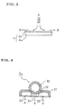
- Fig. 3 shows the supply of the reactive gas (A) and the discharge directions of the gas after the reaction (B), in model-like fashion.
- the reactive gas (A) is vertically supplied to the film surface of the film body 6b of the traveling tape-formed wire material 6 in which this film body 6b being the superconductor preform is formed on the surface of the tape-formed substrate 6a, while the gas after the reaction (B) is discharged from both the sides of the film surface along this film surface.
- Fig. 4 shows the cross section of the reactive gas supply pipe 3a.
- the reactive gas supply pipe 3a has such a shape that a rectangular pipe 31 is coupled to the lower part of a cylindrical pipe 30.
- Two openings 32 for emitting the gas from the cylindrical pipe 30 into the rectangular pipe 31 are provided at an angle of 60 degrees with respect to the center axis of the cylindrical pipe 30.
- the openings 32 are provided in only one place of the right end of the reactive gas supply pipe 3a as viewed in Fig. 1.
- the rectangular pipe 31 is provided with the three gas supply ports 33 at predetermined intervals, and these gas supply ports 33 are provided in a large number at predetermined intervals along the axial direction of the reactive gas supply pipe 3a.
- the reactive gas is emitted from the cylindrical pipe 30 into the rectangular pipe 31 through the openings 32, and it is vertically supplied from the large number of gas supply ports 33 to the tape-formed wire material. 6 while advancing in the reverse direction to the traveling direction of this tape-formed wire material 6 and being heated.
- the reactive gas supply pipe 3b has the same structure as that of the reactive gas supply pipe 3a.
- a manufacturing apparatus 10 was configured of a cylindrical heater 1 which had a length of 1000 mn, a tubular furnace 2 which had a length of 1460 mn and an inside diameter of 216 mm, reactive gas supply pipes 3a and 3b each of which was constituted by a cylindrical pipe 30 having an inside diameter of 12.5 mm and a rectangular pipe 31 having an inner width of 36.5 mm, discharge pipes 4a, 4b, 4c and 4d for discharging the gas after the reaction, each of which had an inside diameter of 12.5 mm, and a pair of reels 5a and 5b which had an interaxial distance of 400 mm and each of which had an outside diameter of 100 mm.
- the reactive gas supply pipes 3a and 3b were formed under the conditions that the diameter of each opening 32 was 6 mm, that the diameter of each gas supply port 33 was 0.35 mm, that the intervals of the gas supply ports 33 in the widthwise direction of the rectangular pipe 31 were 13 mm, that the distribution length of the gas supply ports 33 in the lengthwise direction of the rectangular pipe 31 was 300 mm, and that the intervals of the gas supply ports 33 in the axial direction of each reactive gas supply pipe were 2 mm.
- a tape-formed wire material was manufactured as stated below. There was prepared that mixed solution of a trifluoroacetate salt (TEA salt) in which individual metal elements constituting a YBCO-type (123) superconductor were contained at predetermined mol ratios, and the surface of a tape-formed substrate was coated with the mixed solution by spin coating. Thereafter, the resulting substrate was calcined while a mixed gas in which oxygen and water vapor were contained in argon gas was being supplied at low temperatures of and below 400 °C, whereby the film body of a superconductor preform having a thickness of 2.0 ⁇ m was formed on the substrate surface.
- TAA salt trifluoroacetate salt
- film bodies being superconductor preforms were reacted into superconducting layers by employing tape-formed wire materials which had widths of 10 - 30 mm, and in a furnace which was held at temperatures of 725 - 800 °C, in such a way that a mixed gas in which oxygen and water vapor were contained in argon gas was supplied from one side along the film surface of each film body, and that the gas after the reaction was discharged from the other side.
- Fig. 5 shows the relationship thus obtained between the growth rate of the crystal of the superconducting layer formed on the surface of the tape-formed substrate and a distance from one end of the tape-formed substrate. Besides, in the figure, the growth rate of the crystal as is calculated under the same conditions is simultaneously shown.
- the growth rate of the crystal decreases drastically. That is, the growth rate of the crystal on the discharge side of the gas after the reaction becomes much lower as compared with that of the crystal on the supply side of the reactive gas, and it becomes difficult to form a superconducting layer which has uniform characteristics in the widthwise direction of the substrate.
- a film body being a superconductor preform was reacted into a superconducting layer in such a way that a tape-formed wire material in which the film body being the superconductor preform was formed on the surface of a tape-formed substrate having a width of 30 mm was caused to continuously travel at a speed of 0.26 m/h in the tubular furnace 2 which was held at temperatures of 725 - 800 °C, and that a mixed gas in which oxygen and water vapor were contained in argon gas was vertically supplied to the film surface of the film body by a 3-nozzle scheme, while the gas after the reaction was discharged from both the sides of the film surface along this film surface.
- Fig. 6 shows the relationship thus obtained between the widthwise position of the superconducting layer and the growth rate of the crystal of the superconducting layer.
- a tape-formed wire material in which a film body being a superconductor preform was formed on the surface of a substrate was caused to continuously travel in the tubular furnace, by the same method as in Example 1.
- the film body being the superconductor preform was reacted into a superconducting layer in such a way that a mixed gas in which oxygen and water vapor were contained in argon gas was vertically supplied to the central part of the film surface of the film body in the tubular furnace by a 1-nozzle scheme, while the gas after the reaction was discharged from both the sides of the film surface along this film surface.
- the reactive gas supply pipes 3a and 3b in Fig. 4 ones whose rectangular pipes 31 were provided with the gas supply ports 33 in only central parts were used.
- a tape-formed wire material in which a film body being a superconductor preform was formed on the surface of a substrate was caused to continuously travel in the tubular furnace, by the same method as in Example 1.
- a reactive gas was supplied from a gas supply port provided on one side along the film surface of the film body in the tubular furnace, while a gas after the reaction was discharged from a gas discharge port provided on the opposite side along the film surface.
- Examples 1 and 2 and the comparative example reveal the following: With the method based on the parallel flow gas in the comparative example, there is demonstrated a tendency in which the growth rate of the crystal lowers drastically from the supply side of the supply gas toward the discharge side of the gas after the reaction and becomes nonuniform, for the reason that the concentration of a discharge substance after the reaction becomes higher from the supply side of the reactive gas toward the discharge side of the gas after the reaction, in the widthwise direction of the tape. In contrast, with that 1-nozzle scheme of Example 2 in which the gas supply ports 33 are provided in the central parts, the growth rate of the crystal is uniform over the widthwise direction of the superconducting layer.
- a film body being a superconductor preform was reacted into a layer by the same method as in Example 1, except that a tape-formed wire material in which the film body was formed on the surface of a tape-formed substrate having a width of 10 mm was employed, and that the tape-formed wire material was extended between the pair of reels 5a and 5b by 3 turns.
- Fig. 7 shows the result of Example 3, and the growth rate of the crystal is uniform over the widthwise direction of the superconducting layer as in Example 1.
- the discrepancy of the growth rates of the crystal in Fig. 7 and Example 1 (Fig. 6) depends upon the difference of the supply rates (flow velocities) of the reactive gas.
- the invention permits to quickly manufacture a tape-formed oxide superconductor which is large in area and elongate in shape. Especially, the invention is applicable to the manufacture of a tape-formed oxide superconductor of excellent characteristics by organometallic salt coating and thermodeoomposition (MOD).
- MOD organometallic salt coating and thermodeoomposition
Landscapes
- Engineering & Computer Science (AREA)
- Mechanical Engineering (AREA)
- General Engineering & Computer Science (AREA)
- Manufacturing & Machinery (AREA)
- Superconductors And Manufacturing Methods Therefor (AREA)
Abstract
Description
- The present invention relates to improvements in a method of and an apparatus for manufacturing a tape-formed oxide superconductor.
- Heretofore, as a method of manufacturing a tape-formed oxide superconductor of YBCO type (Y-Ba-Cu-O) suitable for applications to superconducting magnets, superconducting cables, and electric power machines and instruments, there has been known one based on organometallic salt coating and thermodecomposition (or MOD short for metal organic deposition) capable of manufacturing the tape-formed oxide superconductor by a non-vacuum process.
- With this method, a superconducting layer is formed in such a way that an intermediate layer is formed on a substrate, that the substrate bearing the intermediate layer is coated with that mixed solution of trifluoroacetate salt (TFA salt) or the like metal organic acid salt such as octylic acid salt or naphthenic acid salt in which individual metal elements constituting the superconductor are contained at predetermined mol ratios, and that the resulting substrate is calcined, followed by a heat treatment.
- In order to make such a tape-formed oxide superconductor elongate, a tubular furnace is employed as a treatment furnace. Heretofore, an atmosphere in the furnace has been controlled by causing an atmosphere gas (reactive gas) to flow from one end to the other end of a furnace core tube. It has been known that, when the gas is caused to flow to the elongate material in the axial direction of the furnace core tube in this manner, the atmosphere changes in the axial direction of the furnace core tube under the influence of a gas which is generated from the elongate material during a reaction, so the elongate material becomes very difficult of being uniformly reacted.
- Especially in a method (TE2\-MD method) wherein a YBOC film is formed in such a way that the film of a preform obtained by the calcination of the above TEA salt and containing F (ex-situ method) is formed on a tape surface, and that it is thereafter heat-treated, HF is generated during the calcination and the heat treatment for the reasons that the element F is contained in the preform film and that water vapor is used during the heat treatment. This poses the problem that superconducting characteristics degrade under the influence of HF gas generated after the reaction.
- For the purpose of suppressing the influence of the gas after the reaction and holding the atmosphere in the furnace constant in order to avoid such a problem, the reactive gas needs to flow along the tape surface in a direction vertical to the axial direction of the furnace core tube.
- As an atmosphere control type heat treatment furnace wherein the reactive gas is caused to flow along the tape surface in the direction vertical to the axial direction of the furnace core tube, there has been known one in which a plurality of gas flow passages are formed by a furnace core tube that is configured of an outer tube and an inner tube arranged concentrically, and partition plates that divides a cylindrical space defined by the outer tube and the inner tube, into a plurality of parts within a section vertical to the axial direction of the furnace core tube, and in which pluralities of gas outflow ports and gas inflow ports are respectively provided at substantially the opposing positions of the inner tube in the plurality of gas flow passages (refer to Patent Document 1).
- Patent Document 1:
JP-A-2003-121076 page 2, right column, lines 24 - 31 and lines 37 - 41, and Figs. 1 - 4) - In the atmosphere control type heat treatment furnace wherein the reactive gas is caused to flow along the tape surface in the direction vertical to the axial direction of the furnace core tube, the homogeneous gas is supplied at different flow velocities to the gas flow passages having the pluralities of gas outflow ports and gas inflow ports, whereby a pressure difference can be established between the gas outflow ports and the gas inflow ports, and the reactive gas can be caused to uniformly flow along the tape surface in the direction vertical to the axial direction of the furnace core tube.
- Regarding the above method, however, the following fact has been revealed: When a tape-formed wire material in which a film body being a superconductor preform is formed on a substrate of large area (large width) is caused to continuously travel in the furnace, so as to react the film body into a superconducting layer, the growth rate of a crystal differs in the widthwise direction of the tape. More specifically, the crystal growth rate on the discharge side of a gas after the reaction becomes much lower as compared with that on the supply side of the reactive gas. It is accordingly difficult to form a superconducting layer which has uniform characteristics in the widthwise direction of the surface of the substrate.
- There has consequently been the problem that a tape-formed oxide superconductor of large area (large width) is difficult of being obtained.
- The present invention has been made in order to solve the above problem, and it has for its object to provide a manufacturing method which can quickly manufacture a tape-formed oxide superconductor of large area (large width) having uniform superconducting characteristics in the widthwise direction thereof, and an apparatus which is suited to the manufacturing method.
- In order to accomplish the object, a method of manufacturing a tape-formed oxide superconductor according to the invention consists in comprising the steps of causing a tape-formed wire material in which a film body being a superconductor preform is formed on a surface of a tape-formed substrate, to continuously travel in a heating zone; and supplying a reactive gas vertically to a film surface of the film body in the heating zone, and simultaneously discharging a gas after a reaction from both sides of the film surface along the film surface, thereby to react and crystallize the film body into a superconducting layer.
- In this case, it is preferable that the reactive gas is supplied from a plurality of places along a traveling direction of the tape-formed wire material, while the gas after the reaction is discharged from a plurality of places on both sides along the film surfaces in correspondence with the supply of the reactive gas.
- Besides, in the above case, it is preferable that the reactive gas is supplied from the plurality of places in correspondence with a widthwise direction of the film surface.
- Besides, in order to simultaneously achieve the enlarged area of the tape-formed oxide superconductor and the heightened speed of the manufacture, the tape-formed wire material can be extended between a pair of reels disposed within the heating zone, so that the tape-formed substrate may lie in touch with the reels by at least one turn, and the reactive gas can be supplied vertically to the respective film surfaces traveling between the reels.
- In this case, the reactive gas is supplied to the respective film surfaces of the tape-formed wire material which is extended and inverted between the reels, and the gas after the reaction is discharged from both the sides of the film surfaces along these film surfaces. As in the foregoing, it is preferable that the reactive gas is supplied from a plurality of places along the traveling direction of the tape-formed wire material, while the gas after the reaction is discharged from a plurality of places on both the sides along the film surfaces in correspondence with the supply of the reactive gas, and that the reactive gas is supplied from pluralities of places in correspondence with the widthwise directions of the film surfaces.
- The above method of manufacturing a tape-formed oxide superconductor is well suited for application to a case where the film body of the superconductor preform on the surface of the tape-shaped substrate has been formed by coating the tape-formed substrate with a mixture of a metalorganic acid salt containing elements which constitute an REl23-type superconductor (where "RE" denotes at least one element selected from the group consisting of La, Nd, Sm, Eu, Gd, Dy, Ho, Er, 7kn, Yb, Lu and Y, and thereafter calcining the resulting substrate.
- Further, in order to accomplish the object, an apparatus for manufacturing a tape-formed oxide superconductor according to the invention consists in an apparatus for manufacturing a superconductor by heating and reacting a tape-formed wire material in which a film body being a superconductor preform is formed on a surface of a tape-formed substrate; an apparatus for manufacturing a tape-formed oxide superconductor, comprising (a) a tubular furnace in which the tape-formed wire material travels continuously; (b) a gas supply port which serves to supply a reactive gas vertically to a film surface of the film body in the tubular furnace; and (c) gas discharge ports which serve to discharge a gas after the reaction, from both sides of the film surface along the film surface.
- In the above apparatus, it is preferable to provide the gas supply ports in a plurality of places along a traveling path of the tape-formed wire material, and to provide the gas discharge ports in a plurality of places on both sides in correspondence with the gas supply ports . In this case, it is preferable to provide the gas supply ports in a plurality of places in correspondence with a widthwise direction of the film surface.
- Besides, the object of the invention concerns an apparatus for manufacturing a superconductor by heating and reacting a tape-formed wire material in which a film body being a superconductor preform is formed on a surface of a tape-formed substrate; an apparatus for manufacturing a tape-formed oxide superconductor, and it can be accomplished by an apparatus for manufacturing a tape-formed oxide superconductor, comprising (a) a tubular furnace in which the tape-formed wire material travels continuously; (b) a pair of reels which are disposed within the tubular furnace in order to extend the tape-formed wire material therebetween; (c) a plurality of gas supply ports which are provided along a traveling direction of the tape-formed wire material in order to supply a reactive gas vertically to film surfaces of the respective film bodies of the tape-formed wire material extended and traveling between the pair of reels; and(d) a plurality of gas discharge ports which are provided on both sides along the film surfaces in order to discharge a gas after the reaction, from over the film surfaces in correspondence with the gas supply ports.
- In the above apparatus, it is preferable to provide the gas supply ports in pluralities of places in correspondence with a widthwise directions of the film surfaces.
- According to the invention, a tape-formed oxide superconductor in which the growth rate of the crystal of a superoonductinq layer is uniform over the widthwise direction of a tape can be manufactured, and a tape-formed oxide superconductor of large area and elongate shape as is at least 30 mm can be manufactured at high speed by organometallic salt coating and thermodecomposition (MD). Therefore, the invention is greatly valuable in practical use.
-
- Fig. 1 is a schematic vertical sectional view containing the axial direction of a furnace core tube, showing an embodiment of an apparatus for manufacturing a tape-formed oxide superconductor according to the present invention;
- Fig. 2 is a sectional view taken perpendicularly to the axial direction of the furnace core tube of the apparatus for manufacturing a tape-foimed oxide superconductor as shown in Fig. 1;
- Fig. 3 is a model diagram showing the supply of a reactive gas (A) and the discharge directions of a gas after a reaction (B), in a method of manufacturing a tape-formed oxide superconductor according to the invention;
- Fig. 4 is a sectional view of a reactive gas supply pipe 3a for use in the apparatus for manufacturing a tape-formed oxide superconductor according to the present invention;
- Fig. 5 is a graph showing the relationship between the widthwise position of a super layer and the growth rate of the crystal of the superconducting layer as based on a parallel flow scheme in the prior art;
- Fig. 6 is a graph showing the relationships between the widthwise positions of superconductor layers formed on substrates and the growth rates of the crystals of the superconductor layers, these superconductor layers having been manufactured by methods of manufacturing a tape-formed oxide superconductor according to examples of the invention and a comparative example; and
- Fig. 7 is a graph showing the relationship between the widthwise position of a superconductor layer formed on a substrate and the growth rate of the crystal of the superconductor layer, this superconductor layer having been manufactured by a method of manufacturing a tape-formed oxide superconductor according to another example of the invention.
- Fig. 1 is a schematic vertical sectional view containing the axial direction of a furnace core tube, showing an embodiment of an
apparatus 10 for manufacturing a tape-formed oxide superconductor according to the present invention, while Fig. 2 is a sectional view taken perpendicularly to the axial direction of the furnace core tube. Now, the embodiment will be described with reference to Figs. 1 and 2. - Referring to Figs. 1 and 2,
numeral 1 designates a cylindrical heater,numeral 2 designates a tubular furnace which is disposed concentrically with theheater 1, signs 3a and 3b designate reactive gas supply pipes which are respectively disposed at the upper and lower parts of the interior of thetubular furnace 2,signs tubular furnace 2, andsigns tubular furnace 2. - The
heater 1 is disposed at the axial middle part of thetubular furnace 2 outside thistubular furnace 2, and the pair ofreels heater 1. - The reactive gas supply pipe 3a is disposed with its gas supply ports located over an upper side film surface, in order to supply a reactive gas fran a vertical direction to the upper side film surface of the tape-formed
wire material 6 which is extended between the pair ofreels wire material 6 which is extended between the pair ofreels - The
discharge pipes 4a and 4b for discharging the gas after the reaction are disposed with their gas discharge ports located along both the sides of the upper side film surface, in order that the gas after the reaction may be discharged from both the sides along the upper side film surface of the tape-formedwire material 6 which is extended between the pair ofreels discharge pipes wire material 6 which is extended between the pair ofreels - In such an apparatus, the tape-formed
wire material 6, in which a film body being a superconductor preform is formed on the surface of a tape-formed substrate, is supplied into thetubular furnace 2 from the left side as viewed in Fig. 1, and it is extended between the pair ofreels wire material 6 can also be extended and caused to travel between the pair ofreels - The tape-formed
wire material 6 extended between the pair ofreels discharge pipes 4a and 4b for discharging this gas after the reaction. Likewise, the tape-formedwire material 6 extended between the pair ofreels discharge pipes - Fig. 3 shows the supply of the reactive gas (A) and the discharge directions of the gas after the reaction (B), in model-like fashion. The reactive gas (A) is vertically supplied to the film surface of the film body 6b of the traveling tape-formed
wire material 6 in which this film body 6b being the superconductor preform is formed on the surface of the tape-formed substrate 6a, while the gas after the reaction (B) is discharged from both the sides of the film surface along this film surface. - Fig. 4 shows the cross section of the reactive gas supply pipe 3a. The reactive gas supply pipe 3a has such a shape that a
rectangular pipe 31 is coupled to the lower part of acylindrical pipe 30. Twoopenings 32 for emitting the gas from thecylindrical pipe 30 into therectangular pipe 31 are provided at an angle of 60 degrees with respect to the center axis of thecylindrical pipe 30. Besides, theopenings 32 are provided in only one place of the right end of the reactive gas supply pipe 3a as viewed in Fig. 1. Therectangular pipe 31 is provided with the threegas supply ports 33 at predetermined intervals, and thesegas supply ports 33 are provided in a large number at predetermined intervals along the axial direction of the reactive gas supply pipe 3a. - The reactive gas is emitted from the
cylindrical pipe 30 into therectangular pipe 31 through theopenings 32, and it is vertically supplied from the large number ofgas supply ports 33 to the tape-formed wire material. 6 while advancing in the reverse direction to the traveling direction of this tape-formedwire material 6 and being heated. Also the reactive gas supply pipe 3b has the same structure as that of the reactive gas supply pipe 3a. - In the
apparatus 10 for manufacturing a tape-formed oxide superconductor as shown in Figs. 1 and 2, and the reactive gas supply pipes 3a and 3b shown in Fig. 4, amanufacturing apparatus 10 was configured of acylindrical heater 1 which had a length of 1000 mn, atubular furnace 2 which had a length of 1460 mn and an inside diameter of 216 mm, reactive gas supply pipes 3a and 3b each of which was constituted by acylindrical pipe 30 having an inside diameter of 12.5 mm and arectangular pipe 31 having an inner width of 36.5 mm,discharge pipes reels - Incidentally, the reactive gas supply pipes 3a and 3b were formed under the conditions that the diameter of each
opening 32 was 6 mm, that the diameter of eachgas supply port 33 was 0.35 mm, that the intervals of thegas supply ports 33 in the widthwise direction of therectangular pipe 31 were 13 mm, that the distribution length of thegas supply ports 33 in the lengthwise direction of therectangular pipe 31 was 300 mm, and that the intervals of thegas supply ports 33 in the axial direction of each reactive gas supply pipe were 2 mm. - A tape-formed wire material was manufactured as stated below. There was prepared that mixed solution of a trifluoroacetate salt (TEA salt) in which individual metal elements constituting a YBCO-type (123) superconductor were contained at predetermined mol ratios, and the surface of a tape-formed substrate was coated with the mixed solution by spin coating. Thereafter, the resulting substrate was calcined while a mixed gas in which oxygen and water vapor were contained in argon gas was being supplied at low temperatures of and below 400 °C, whereby the film body of a superconductor preform having a thickness of 2.0 µm was formed on the substrate surface.
- film bodies being superconductor preforms were reacted into superconducting layers by employing tape-formed wire materials which had widths of 10 - 30 mm, and in a furnace which was held at temperatures of 725 - 800 °C, in such a way that a mixed gas in which oxygen and water vapor were contained in argon gas was supplied from one side along the film surface of each film body, and that the gas after the reaction was discharged from the other side.
- Fig. 5 shows the relationship thus obtained between the growth rate of the crystal of the superconducting layer formed on the surface of the tape-formed substrate and a distance from one end of the tape-formed substrate. Besides, in the figure, the growth rate of the crystal as is calculated under the same conditions is simultaneously shown.
- As seen from the figure, when the width of the substrate becomes large relative to a parallel flow, the growth rate of the crystal decreases drastically. That is, the growth rate of the crystal on the discharge side of the gas after the reaction becomes much lower as compared with that of the crystal on the supply side of the reactive gas, and it becomes difficult to form a superconducting layer which has uniform characteristics in the widthwise direction of the substrate.
- Using the
apparatus 10 for manufacturing a tape-formed oxide superconductor as shown in Figs. 1 and 2, a film body being a superconductor preform was reacted into a superconducting layer in such a way that a tape-formed wire material in which the film body being the superconductor preform was formed on the surface of a tape-formed substrate having a width of 30 mm was caused to continuously travel at a speed of 0.26 m/h in thetubular furnace 2 which was held at temperatures of 725 - 800 °C, and that a mixed gas in which oxygen and water vapor were contained in argon gas was vertically supplied to the film surface of the film body by a 3-nozzle scheme, while the gas after the reaction was discharged from both the sides of the film surface along this film surface. - Fig. 6 shows the relationship thus obtained between the widthwise position of the superconducting layer and the growth rate of the crystal of the superconducting layer.
- A tape-formed wire material in which a film body being a superconductor preform was formed on the surface of a substrate was caused to continuously travel in the tubular furnace, by the same method as in Example 1. The film body being the superconductor preform was reacted into a superconducting layer in such a way that a mixed gas in which oxygen and water vapor were contained in argon gas was vertically supplied to the central part of the film surface of the film body in the tubular furnace by a 1-nozzle scheme, while the gas after the reaction was discharged from both the sides of the film surface along this film surface. In this case, as the reactive gas supply pipes 3a and 3b in Fig. 4, ones whose
rectangular pipes 31 were provided with thegas supply ports 33 in only central parts were used. - The relationship thus obtained between the widthwise position of the superconducting layer and the growth rate of the crystal of the superconducting layer is also shown in Fig. 6.
- A tape-formed wire material in which a film body being a superconductor preform was formed on the surface of a substrate was caused to continuously travel in the tubular furnace, by the same method as in Example 1. A reactive gas was supplied from a gas supply port provided on one side along the film surface of the film body in the tubular furnace, while a gas after the reaction was discharged from a gas discharge port provided on the opposite side along the film surface.
- The relationship thus obtained between the widthwise position of the superconducting layer and the growth rate of the crystal of the layer is also shown in Fig. 6.
- The shown results of Examples 1 and 2 and the comparative example reveal the following: With the method based on the parallel flow gas in the comparative example, there is demonstrated a tendency in which the growth rate of the crystal lowers drastically from the supply side of the supply gas toward the discharge side of the gas after the reaction and becomes nonuniform, for the reason that the concentration of a discharge substance after the reaction becomes higher from the supply side of the reactive gas toward the discharge side of the gas after the reaction, in the widthwise direction of the tape. In contrast, with that 1-nozzle scheme of Example 2 in which the
gas supply ports 33 are provided in the central parts, the growth rate of the crystal is uniform over the widthwise direction of the superconducting layer. Besides, with that 3-nozzle scheme of Example 1 in which thegas supply ports 33 are provided in the central parts and on both the sides thereof, not on1.y the growth rate of the crystal is uniform over the widthwise direction of the layer, but also the growth rate of the crystal is entirely much better than that with the 1-nozzle scheme. - A film body being a superconductor preform was reacted into a layer by the same method as in Example 1, except that a tape-formed wire material in which the film body was formed on the surface of a tape-formed substrate having a width of 10 mm was employed, and that the tape-formed wire material was extended between the pair of
reels - Fig. 7 shows the result of Example 3, and the growth rate of the crystal is uniform over the widthwise direction of the superconducting layer as in Example 1. The discrepancy of the growth rates of the crystal in Fig. 7 and Example 1 (Fig. 6) depends upon the difference of the supply rates (flow velocities) of the reactive gas.
- The invention permits to quickly manufacture a tape-formed oxide superconductor which is large in area and elongate in shape. Especially, the invention is applicable to the manufacture of a tape-formed oxide superconductor of excellent characteristics by organometallic salt coating and thermodeoomposition (MOD).
Claims (9)
- A method of manufacturing a tape-formed oxide superconductor, comprising the steps of causing a tape-formed wire material in which a film body being a superconductor preform is formed on a surface of a tape-formed substrate, to continuously travel in a heating zone; and supplying a reactive gas vertically to a film surface of the film body in the heating zone, and simultaneously discharging a gas after a reaction from both sides of the film surface along the film surface, thereby to react and crystallize the film body into a layer.
- A method of manufacturing a tape-formed oxide superconductor as defined in claim 1, wherein the reactive gas is supplied from a plurality of places along a traveling direction of the tape-formed wire material, while the gas after the reaction is discharged from a plurality of places on both sides along the film surfaces in correspondence with the supply of the reactive gas.
- A method of manufacturing a tape-formed oxide superconductor as defined in claim 1 or 2, wherein the reactive gas is supplied from the plurality of places in correspondence with a widthwise direction of the film surface.
- A method of manufacturing a tape-formed oxide superconductor as defined in any of claims 1 through 3, wherein the tape-formed wire material is extended between a pair of reels disposed within the heating zone, so that the tape-formed substrate may lie in touch with the reels by at least one turn, and the reactive gas is supplied vertically to the respective film surfaces traveling between the reels.
- A method of manufacturing a tape-formed oxide superconductor as defined in any of claims 1 through 5, wherein the film body of the superconductor preform has been formed by coating the tape-formed substrate with a mixture of a metalorganic acid salt containing elements which constitute an RE123-type superconductor (where '"RE" denotes at least one element selected from the group consisting of La, Nd, Sm, Eu, Gd, Dy, Ho, Er, Tm, Yb, Lu and Y, and thereafter calcining the resulting substrate.
- In an apparatus for manufacturing a superconductor by heating and reacting a tape-formed wire material in which a film body being a superconductor preform is formed on a surface of a tape-formed substrate; an apparatus for manufacturing a tape-formed oxide superconductor, comprising:(a) a tubular furnace in which the tape-formed wire material travels continuously;(b) a gas supply port which serves to supply a reactive gas vertically to a film surface of the film body in said tubular furnace; and(c) gas discharge ports which serve to discharge a gas after the reaction, from both sides of the film surface along the film surface.
- An apparatus for manufacturing a tape-formed oxide superconductor as defined in claim 6, wherein the gas supply ports are provided in a plurality of places along a traveling path of the tape-formed wire material, and the gas discharge ports are provided in a plurality of places on both sides in correspondence with the gas supply ports.
- An apparatus for manufacturing a tape-formed oxide superconductor as defined in claim 6 or 7, wherein the gas supply ports are provided in a plurality of places in correspondence with a widthwise direction of the film surface.
- In an apparatus for manufacturing a superconductor by heating and reacting a tape-formed wire material in which a film body being a superconductor preform is formed on a surface of a tape-formed substrate; an apparatus for manufacturing a tape-formed oxide superconductor, an apparatus for manufacturing a tape-formed oxide superconductor, comprising:(a) a tubular furnace in which the tape-formed wire material travels continuously;(b) a pair of reels which are disposed within said tubular furnace in order to extend the tape-formed wire material therebetween;(c) a plurality of gas supply ports which are provided along a traveling direction of the tape-formed wire material in order to supply a reactive gas vertically to film surfaces of the respective film bodies of the tape-formed wire material extended and traveling between said pair of reels; and(d) a plurality of gas discharge ports which are provided on both sides along the film surfaces in order to discharge a gas after the reaction, from over the film surfaces in correspondence with said gas supply ports.
Applications Claiming Priority (1)
| Application Number | Priority Date | Filing Date | Title |
|---|---|---|---|
| JP2005088798A JP4401992B2 (en) | 2005-03-25 | 2005-03-25 | Tape-like oxide superconducting wire manufacturing method and manufacturing apparatus thereof |
Publications (2)
| Publication Number | Publication Date |
|---|---|
| EP1705720A2 true EP1705720A2 (en) | 2006-09-27 |
| EP1705720A3 EP1705720A3 (en) | 2009-03-25 |
Family
ID=36588950
Family Applications (1)
| Application Number | Title | Priority Date | Filing Date |
|---|---|---|---|
| EP06006034A Withdrawn EP1705720A3 (en) | 2005-03-25 | 2006-03-23 | Method of and apparatus for manufacturing tape-formed oxide superconductor |
Country Status (3)
| Country | Link |
|---|---|
| US (1) | US8124171B2 (en) |
| EP (1) | EP1705720A3 (en) |
| JP (1) | JP4401992B2 (en) |
Cited By (1)
| Publication number | Priority date | Publication date | Assignee | Title |
|---|---|---|---|---|
| EP1959509A1 (en) * | 2007-02-15 | 2008-08-20 | Zenergy Power GmbH | Method for manufacturing a high temperature superconductor tape |
Families Citing this family (3)
| Publication number | Priority date | Publication date | Assignee | Title |
|---|---|---|---|---|
| JP5837751B2 (en) * | 2011-02-03 | 2015-12-24 | 昭和電線ケーブルシステム株式会社 | Tape-like oxide superconducting wire manufacturing method and heat treatment apparatus |
| JP5881953B2 (en) * | 2011-02-03 | 2016-03-09 | 公益財団法人国際超電導産業技術研究センター | Tape-like oxide superconducting wire manufacturing method |
| CN107449279A (en) * | 2017-07-14 | 2017-12-08 | 赣州齐畅新材料有限公司 | A kind of electrical kiln for calcination high purity rare earth oxides |
Citations (1)
| Publication number | Priority date | Publication date | Assignee | Title |
|---|---|---|---|---|
| EP0744474A1 (en) | 1995-05-22 | 1996-11-27 | Fujikura Ltd. | Chemical vapor deposition reactor and method of producing oxide superconductive conductor using the same |
Family Cites Families (9)
| Publication number | Priority date | Publication date | Assignee | Title |
|---|---|---|---|---|
| CA1332324C (en) * | 1987-03-30 | 1994-10-11 | Jun Shioya | Method for producing thin film of oxide superconductor |
| US5034372A (en) * | 1987-12-07 | 1991-07-23 | Mitsubishi Denki Kabushiki Kaisha | Plasma based method for production of superconductive oxide layers |
| US4962085A (en) * | 1988-04-12 | 1990-10-09 | Inco Alloys International, Inc. | Production of oxidic superconductors by zone oxidation of a precursor alloy |
| JPH02208209A (en) | 1989-02-08 | 1990-08-17 | Furukawa Electric Co Ltd:The | Production of oxide superconductor precursor |
| JP3880708B2 (en) * | 1997-10-16 | 2007-02-14 | 株式会社フジクラ | Manufacturing apparatus and manufacturing method of oxide superconductor |
| JP3741860B2 (en) | 1998-05-13 | 2006-02-01 | 株式会社フジクラ | Manufacturing apparatus and manufacturing method of oxide superconducting conductor |
| WO2003067672A2 (en) | 2001-07-31 | 2003-08-14 | American Superconductor Corporation | Methods and reactors for forming superconductor layers |
| JP3789341B2 (en) | 2001-10-12 | 2006-06-21 | 財団法人国際超電導産業技術研究センター | Atmosphere controlled heat treatment furnace |
| US20050065035A1 (en) * | 2003-06-10 | 2005-03-24 | Rupich Martin W. | Superconductor methods and reactors |
-
2005
- 2005-03-25 JP JP2005088798A patent/JP4401992B2/en not_active Expired - Lifetime
-
2006
- 2006-03-22 US US11/385,742 patent/US8124171B2/en not_active Expired - Fee Related
- 2006-03-23 EP EP06006034A patent/EP1705720A3/en not_active Withdrawn
Patent Citations (1)
| Publication number | Priority date | Publication date | Assignee | Title |
|---|---|---|---|---|
| EP0744474A1 (en) | 1995-05-22 | 1996-11-27 | Fujikura Ltd. | Chemical vapor deposition reactor and method of producing oxide superconductive conductor using the same |
Cited By (3)
| Publication number | Priority date | Publication date | Assignee | Title |
|---|---|---|---|---|
| EP1959509A1 (en) * | 2007-02-15 | 2008-08-20 | Zenergy Power GmbH | Method for manufacturing a high temperature superconductor tape |
| US7964533B2 (en) | 2007-02-15 | 2011-06-21 | Zenergy Power Gmbh | Method for producing an HTSC strip |
| US8361930B2 (en) | 2007-02-15 | 2013-01-29 | Basf Se | Sintering furnace for producing an HTSC strip |
Also Published As
| Publication number | Publication date |
|---|---|
| EP1705720A3 (en) | 2009-03-25 |
| US20060216407A1 (en) | 2006-09-28 |
| JP4401992B2 (en) | 2010-01-20 |
| US8124171B2 (en) | 2012-02-28 |
| JP2006269347A (en) | 2006-10-05 |
Similar Documents
| Publication | Publication Date | Title |
|---|---|---|
| EP0102489B1 (en) | Multifilament superconductor and method of making the same | |
| CN100367525C (en) | Methods, systems and reactors for producing superconducting materials | |
| EP1975950B1 (en) | Heat treatment apparatus for oxide superconducting wire | |
| US8268386B2 (en) | Method for manufacturing high-temperature superconducting conductors | |
| US8124171B2 (en) | Method of and apparatus for manufacturing tape-formed oxide superconductor | |
| US7910155B2 (en) | Method for manufacturing high temperature superconducting conductor | |
| JP4876044B2 (en) | Heat treatment apparatus for oxide superconducting wire and method for manufacturing the same | |
| JP2953826B2 (en) | Method and apparatus for manufacturing oxide superconductor | |
| JP3771143B2 (en) | Manufacturing method of oxide superconductor | |
| JP3789341B2 (en) | Atmosphere controlled heat treatment furnace | |
| JP4034052B2 (en) | Manufacturing method of oxide superconductor | |
| CN103339692B (en) | Manufacturing method and heat treatment apparatus of tape-shaped oxide superconducting wire | |
| CN103460306B (en) | The manufacture method of banding oxide superconducting wire rod | |
| JP3808250B2 (en) | CVD reactor and oxide superconductor manufacturing method | |
| US10487014B2 (en) | Equipment for manufacturing ceramic wires | |
| JP3880708B2 (en) | Manufacturing apparatus and manufacturing method of oxide superconductor | |
| JP2003308745A (en) | Method and apparatus for manufacturing oxide superconducting wire | |
| JP3771142B2 (en) | Oxide superconducting conductor and manufacturing method thereof | |
| JP3771107B2 (en) | Oxide superconducting conductor, manufacturing apparatus and manufacturing method thereof | |
| WO2002093590A1 (en) | Oxide supercoductor in the form of tape and method for preparation thereof | |
| EP1662514A1 (en) | Process for producing oxide superconductive wire | |
| JP2014072069A (en) | Method of manufacturing oxide superconducting wire |
Legal Events
| Date | Code | Title | Description |
|---|---|---|---|
| PUAI | Public reference made under article 153(3) epc to a published international application that has entered the european phase |
Free format text: ORIGINAL CODE: 0009012 |
|
| AK | Designated contracting states |
Kind code of ref document: A2 Designated state(s): AT BE BG CH CY CZ DE DK EE ES FI FR GB GR HU IE IS IT LI LT LU LV MC NL PL PT RO SE SI SK TR |
|
| AX | Request for extension of the european patent |
Extension state: AL BA HR MK YU |
|
| RIN1 | Information on inventor provided before grant (corrected) |
Inventor name: SHIOHARA, YUHC/O SUPERCONDUCTIVITY RESEARCH LAB. Inventor name: IZUMI, TERUOC/O SUPERCONDUCTIVITY RESEARCH LAB. Inventor name: TERANISHI, RYOC/O DEPT. OF MATERIALS SCIENCE & Inventor name: NOMOTO, SUKEHARUC/O ENERGY &INDUSTRIAL SYS. DEPT. Inventor name: FUJI, HIROSHIC/O METALLIC MATERIAL DEPT. Inventor name: AOKI, YUJIC |
|
| RAP1 | Party data changed (applicant data changed or rights of an application transferred) |
Owner name: FUJIKURA LTD. Owner name: SWCC SHOWA CABLE SYSTEMS CO., LTD. Owner name: INTERNATIONAL SUPERCONDUCTIVITY TECHNOLOGY CENTER, |
|
| PUAL | Search report despatched |
Free format text: ORIGINAL CODE: 0009013 |
|
| AK | Designated contracting states |
Kind code of ref document: A3 Designated state(s): AT BE BG CH CY CZ DE DK EE ES FI FR GB GR HU IE IS IT LI LT LU LV MC NL PL PT RO SE SI SK TR |
|
| AX | Request for extension of the european patent |
Extension state: AL BA HR MK YU |
|
| 17P | Request for examination filed |
Effective date: 20090812 |
|
| 17Q | First examination report despatched |
Effective date: 20090922 |
|
| AKX | Designation fees paid |
Designated state(s): DE FR GB |
|
| GRAP | Despatch of communication of intention to grant a patent |
Free format text: ORIGINAL CODE: EPIDOSNIGR1 |
|
| RIN1 | Information on inventor provided before grant (corrected) |
Inventor name: FUJI, HIROSHI C/O METALLIC MATERIAL DEPT. Inventor name: TERANISHI, RYO C/O DEPARTMENT OF MATERIALS SCIENCE Inventor name: NOMOTO, SUKEHARU C/O IMPACT DYNAMICS & MATERIAL SC Inventor name: IZUMI, TERUO C/O DIVISION OF SUPERCONDUCTING TAPES Inventor name: AOKI, YUJI C/O SUPERCONDUCTOR PROJECT, SWCC SHOWA Inventor name: SHIOHARA, YUH C/O DIVISION OF SUPERCONDUCTING TAPE |
|
| STAA | Information on the status of an ep patent application or granted ep patent |
Free format text: STATUS: THE APPLICATION HAS BEEN WITHDRAWN |
|
| 18W | Application withdrawn |
Effective date: 20130207 |